
Chapter II: PROJECT DESCRIPTION - · PDF fileChapter II: PROJECT DESCRIPTION ... Cross Section...
17
Environmental Impact Assessment Study of Kabeli ‘A’ Hydroelectric Project II - 1 Chapter II: PROJECT DESCRIPTION 2.1 Project Location KAHEP is located on the Kabeli River Basin in Eastern Nepal (Figure No. 2.1). The Kabeli River at the project site is designated as a natural border between the Panchthar and Taplejung districts. The project site is approximately 620 km east of Kathmandu, the capital city of Nepal. Figure 2.1: Location Map of KAHEP The weir of the project is located at the border of Amarpur VDC of Panchthar and Thechambu VDCs of Taplejung district (Figure 2.2). The approximate longitude and latitude of the proposed intake is 87 o 44'56"E and 27 o 16 ' 40"N. The intake, desilting basin, tunnel alignment, surge shaft, penstock pipe, powerhouse and tailrace canal of the project fall within the jurisdiction of Amarpur VDC in the Pachthar District (Figure 2.2). The geographical grid assigned in the survey license for the project does not fall inside the boundary of any National Park, Wildlife Reserve, Hunting Reserve, Wildlife Sanctuary and conservation area. 2.2 Project Access The access to the project area is through an all season 228 km long Mechi Highway connecting Charali at the East West national highway and Taplejung (Figure 2.3). The Mechi Highway starts from Charali, located 4 km east from Birtamod Bazaar in Jhapa Distict and reaches Kabeli Bazaar (202 km) north on the left bank of the Kabeli River after crossing Phikkal, Ilam, Ranke, Phidim and Gopetar. The 60 km Phidim-Kabeli sector of the Mechi Highway is a gravel road (currently upgrading). Apart from this road, seasonal air services are available from Biratnagar to Taplejung that is further 26 km (gravel road) north from the Kabeli Bazaar along the Mechi Highway. The Headworks and powerhouse are the major sites of KAHEP, which are to be connected by motorable roads for the transportation of construction materials. The proposed sites are presently
Transcript of Chapter II: PROJECT DESCRIPTION - · PDF fileChapter II: PROJECT DESCRIPTION ... Cross Section...

Environmental Impact Assessment Study of Kabeli ‘A’ Hydroelectric Project
II - 1
Chapter II: PROJECT DESCRIPTION
2.1 Project Location KAHEP is located on the Kabeli River Basin in Eastern Nepal (Figure No. 2.1). The Kabeli River at the
project site is designated as a natural border between the Panchthar and Taplejung districts. The
project site is approximately 620 km east of Kathmandu, the capital city of Nepal.
Figure 2.1: Location Map of KAHEP
The weir of the project is located at the border of Amarpur VDC of Panchthar and Thechambu VDCs of
Taplejung district (Figure 2.2). The approximate longitude and latitude of the proposed intake is
87o44'56"E and 27o16'40"N. The intake, desilting basin, tunnel alignment, surge shaft, penstock pipe,
powerhouse and tailrace canal of the project fall within the jurisdiction of Amarpur VDC in the Pachthar
District (Figure 2.2).
The geographical grid assigned in the survey license for the project does not fall inside the boundary of any National Park, Wildlife Reserve, Hunting Reserve, Wildlife Sanctuary and conservation area.
2.2 Project Access The access to the project area is through an all season 228 km long Mechi Highway connecting Charali
at the East West national highway and Taplejung (Figure 2.3). The Mechi Highway starts from Charali,
located 4 km east from Birtamod Bazaar in Jhapa Distict and reaches Kabeli Bazaar (202 km) north on
the left bank of the Kabeli River after crossing Phikkal, Ilam, Ranke, Phidim and Gopetar. The 60 km
Phidim-Kabeli sector of the Mechi Highway is a gravel road (currently upgrading). Apart from this road,
seasonal air services are available from Biratnagar to Taplejung that is further 26 km (gravel road)
north from the Kabeli Bazaar along the Mechi Highway.
The Headworks and powerhouse are the major sites of KAHEP, which are to be connected by
motorable roads for the transportation of construction materials. The proposed sites are presently
Environmental Impact Assessment Study of Kabeli ‘A’ Hydroelectric Project
II - 2
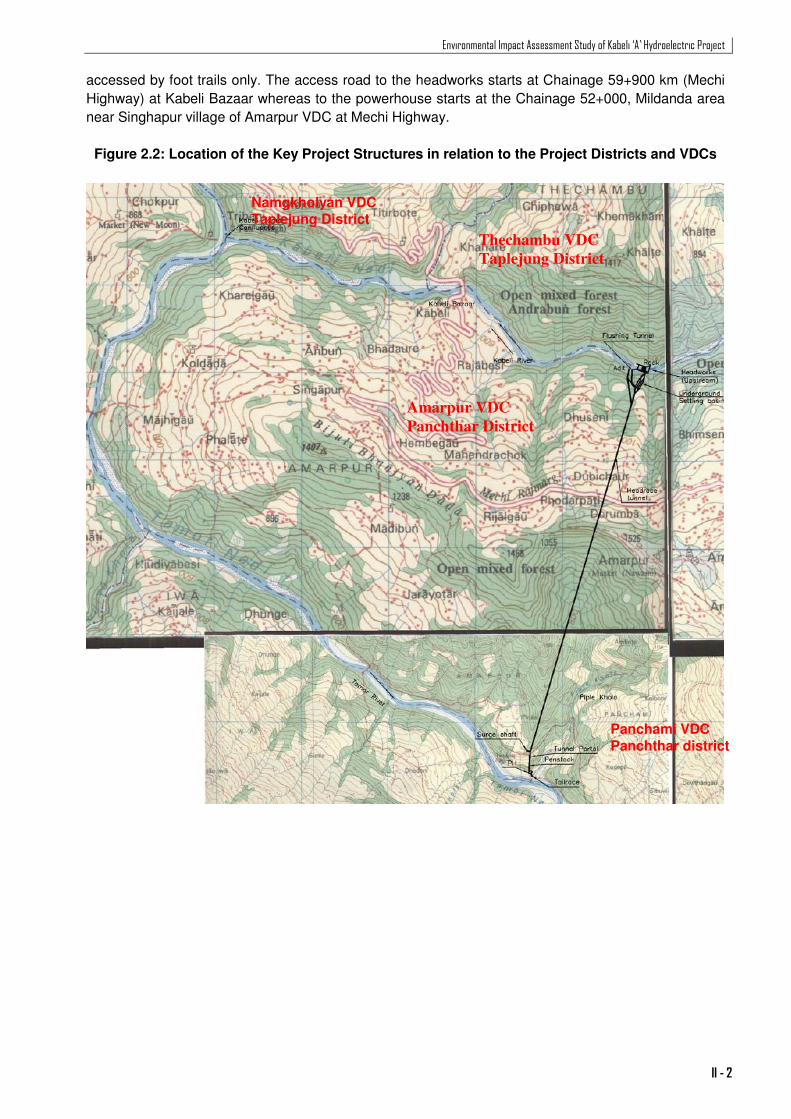
accessed by foot trails only. The access road to the headworks starts at Chainage 59+900 km (Mechi
Highway) at Kabeli Bazaar whereas to the powerhouse starts at the Chainage 52+000, Mildanda area
near Singhapur village of Amarpur VDC at Mechi Highway.
Figure 2.2: Location of the Key Project Structures in relation to the Project Districts and VDCs
Amarpur VDC
Panchthar District
Thechambu VDC
Taplejung District
Namgkholyan VDC Taplejung District
Panchami VDC Panchthar district

Environmental Impact Assessment Study of Kabeli ‘A’ Hydroelectric Project
II - 3
Figure 2.3: Road network linking the project area
2.3 Salient Features of the Project The project is PRoR type with a proposed installed capacity of 34.70 MW with a design discharge
37.73m3/s. The diversion dam with provisions for ponding will be constructed at 2.5 km upstream of
Kabeli Bazaar at Dhuseni village of Amarpur VDC on the left bank and Khudurke Ban of Thechambu
VDC on the right bank. The intake on the left bank will feed the underground settling basin and is
diverted to the Powerhouse located at Tamor River bank close to Pinase village through a 4.322 km
long headrace tunnel. A surface powerhouse will be constructed on the left bank of the Tamor River.
The salient features of the project are presented in Table 2.1.
Environmental Impact Assessment Study of Kabeli ‘A’ Hydroelectric Project
II - 4
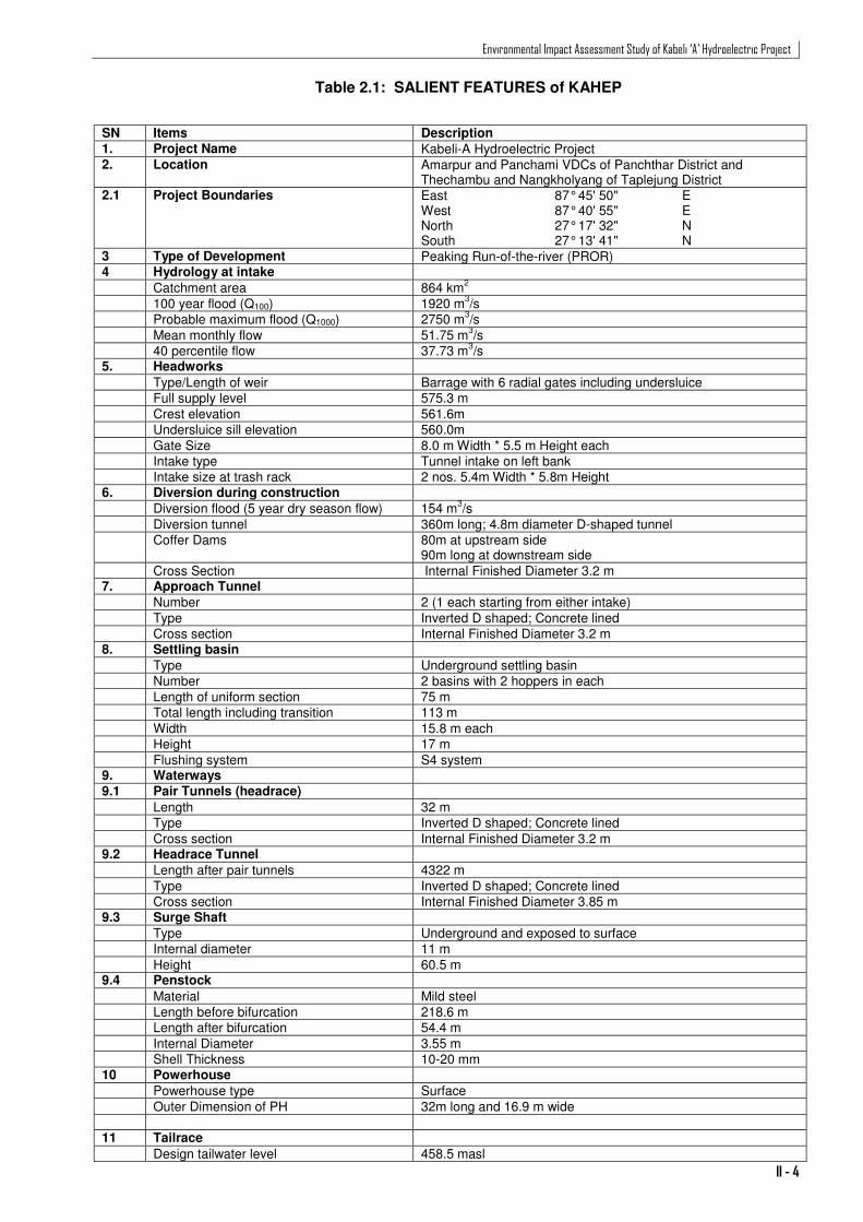
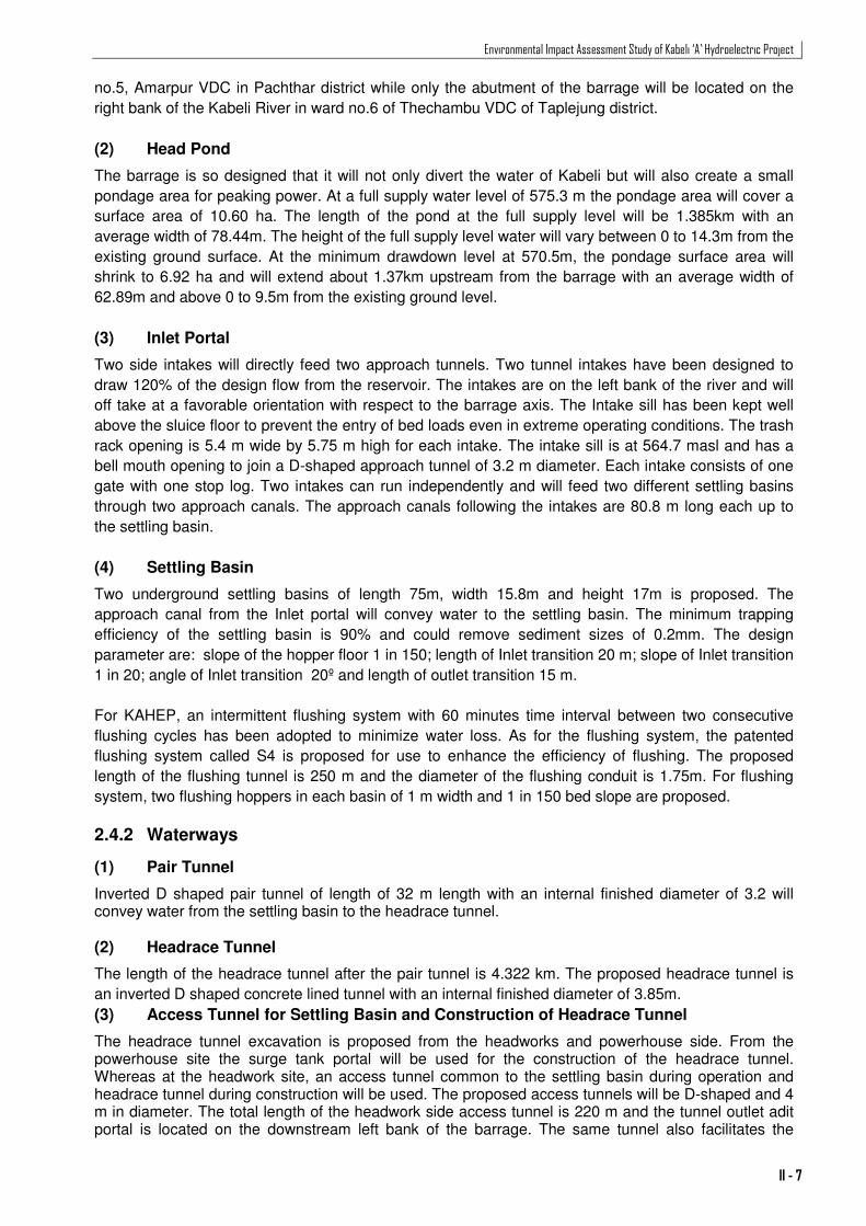
Table 2.1: SALIENT FEATURES of KAHEP
SN Items Description 1. Project Name Kabeli-A Hydroelectric Project 2. Location Amarpur and Panchami VDCs of Panchthar District and
Thechambu and Nangkholyang of Taplejung District 2.1 Project Boundaries East 87° 45' 50" E
West 87° 40' 55" E North 27° 17' 32" N South 27° 13' 41" N
3 Type of Development Peaking Run-of-the-river (PROR) 4 Hydrology at intake Catchment area 864 km
2
100 year flood (Q100) 1920 m3/s
Probable maximum flood (Q1000) 2750 m3/s
Mean monthly flow 51.75 m3/s
40 percentile flow 37.73 m3/s
5. Headworks Type/Length of weir Barrage with 6 radial gates including undersluice Full supply level 575.3 m Crest elevation 561.6m Undersluice sill elevation 560.0m Gate Size 8.0 m Width * 5.5 m Height each Intake type Tunnel intake on left bank Intake size at trash rack 2 nos. 5.4m Width * 5.8m Height 6. Diversion during construction
Diversion flood (5 year dry season flow) 154 m3/s
Diversion tunnel 360m long; 4.8m diameter D-shaped tunnel Coffer Dams 80m at upstream side
90m long at downstream side Cross Section Internal Finished Diameter 3.2 m 7. Approach Tunnel
Number 2 (1 each starting from either intake) Type Inverted D shaped; Concrete lined Cross section Internal Finished Diameter 3.2 m 8. Settling basin
Type Underground settling basin Number 2 basins with 2 hoppers in each Length of uniform section 75 m Total length including transition 113 m Width 15.8 m each Height 17 m Flushing system S4 system 9. Waterways 9.1 Pair Tunnels (headrace)
Length 32 m Type Inverted D shaped; Concrete lined Cross section Internal Finished Diameter 3.2 m 9.2 Headrace Tunnel
Length after pair tunnels 4322 m Type Inverted D shaped; Concrete lined Cross section Internal Finished Diameter 3.85 m 9.3 Surge Shaft
Type Underground and exposed to surface Internal diameter 11 m Height 60.5 m 9.4 Penstock
Material Mild steel Length before bifurcation 218.6 m Length after bifurcation 54.4 m Internal Diameter 3.55 m Shell Thickness 10-20 mm 10 Powerhouse
Powerhouse type Surface Outer Dimension of PH 32m long and 16.9 m wide 11 Tailrace
Design tailwater level 458.5 masl
Environmental Impact Assessment Study of Kabeli ‘A’ Hydroelectric Project
II - 5
Source: KEL, 2010
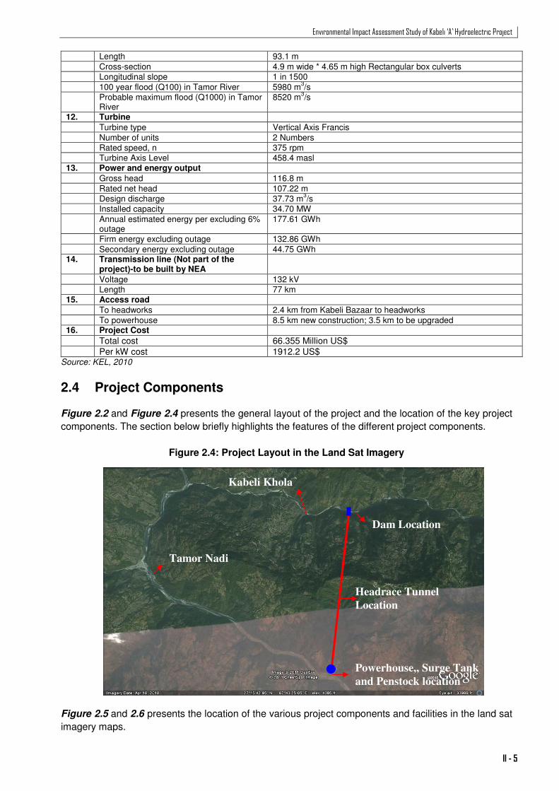
2.4 Project Components Figure 2.2 and Figure 2.4 presents the general layout of the project and the location of the key project
components. The section below briefly highlights the features of the different project components.
Figure 2.4: Project Layout in the Land Sat Imagery
Figure 2.5 and 2.6 presents the location of the various project components and facilities in the land sat
imagery maps.
Length 93.1 m Cross-section 4.9 m wide * 4.65 m high Rectangular box culverts Longitudinal slope 1 in 1500 100 year flood (Q100) in Tamor River 5980 m
3/s
Probable maximum flood (Q1000) in Tamor River
8520 m3/s
12. Turbine
Turbine type Vertical Axis Francis Number of units 2 Numbers Rated speed, n 375 rpm Turbine Axis Level 458.4 masl 13. Power and energy output
Gross head 116.8 m Rated net head 107.22 m Design discharge 37.73 m
3/s
Installed capacity 34.70 MW Annual estimated energy per excluding 6%
outage 177.61 GWh
Firm energy excluding outage 132.86 GWh Secondary energy excluding outage 44.75 GWh 14. Transmission line (Not part of the
project)-to be built by NEA
Voltage 132 kV Length 77 km 15. Access road
To headworks 2.4 km from Kabeli Bazaar to headworks To powerhouse 8.5 km new construction; 3.5 km to be upgraded 16. Project Cost
Total cost 66.355 Million US$ Per kW cost 1912.2 US$
Tamor Nadi
Kabeli Khola
Dam Location
Headrace Tunnel
Location
Powerhouse,, Surge Tank
and Penstock location

Environmental Impact Assessment Study of Kabeli ‘A’ Hydroelectric Project
II - 6
Figure 2.5: Location of Key Facilities at Headworks
Figure 2.6: Locations of Key Facilities at Powerhouse
2.4.1 Headworks
(1) Barrage
The proposed barrage site is located at Amarpur VDC about 4.60 km upstream of its confluence with
Tamor River. The dam will consist of a 14.30 m high and 60m long gated barrage with intake, settling
basin and an underground settling basin on the left bank of Kabeli River near Dhuseni village, ward
Construction camp
Intake and desander
Dam Axis
Spoil disposal sites
Quarry
Quarry site
Powerhouse and switchyard
Labour Camp
Penstock pipe
Surge tank
Spoil Disposal Site
Environmental Impact Assessment Study of Kabeli ‘A’ Hydroelectric Project
II - 7
no.5, Amarpur VDC in Pachthar district while only the abutment of the barrage will be located on the
right bank of the Kabeli River in ward no.6 of Thechambu VDC of Taplejung district.
(2) Head Pond
The barrage is so designed that it will not only divert the water of Kabeli but will also create a small
pondage area for peaking power. At a full supply water level of 575.3 m the pondage area will cover a
surface area of 10.60 ha. The length of the pond at the full supply level will be 1.385km with an
average width of 78.44m. The height of the full supply level water will vary between 0 to 14.3m from the
existing ground surface. At the minimum drawdown level at 570.5m, the pondage surface area will
shrink to 6.92 ha and will extend about 1.37km upstream from the barrage with an average width of
62.89m and above 0 to 9.5m from the existing ground level.
(3) Inlet Portal
Two side intakes will directly feed two approach tunnels. Two tunnel intakes have been designed to
draw 120% of the design flow from the reservoir. The intakes are on the left bank of the river and will
off take at a favorable orientation with respect to the barrage axis. The Intake sill has been kept well
above the sluice floor to prevent the entry of bed loads even in extreme operating conditions. The trash
rack opening is 5.4 m wide by 5.75 m high for each intake. The intake sill is at 564.7 masl and has a
bell mouth opening to join a D-shaped approach tunnel of 3.2 m diameter. Each intake consists of one
gate with one stop log. Two intakes can run independently and will feed two different settling basins
through two approach canals. The approach canals following the intakes are 80.8 m long each up to
the settling basin.
(4) Settling Basin
Two underground settling basins of length 75m, width 15.8m and height 17m is proposed. The
approach canal from the Inlet portal will convey water to the settling basin. The minimum trapping
efficiency of the settling basin is 90% and could remove sediment sizes of 0.2mm. The design
parameter are: slope of the hopper floor 1 in 150; length of Inlet transition 20 m; slope of Inlet transition
1 in 20; angle of Inlet transition 20º and length of outlet transition 15 m.
For KAHEP, an intermittent flushing system with 60 minutes time interval between two consecutive
flushing cycles has been adopted to minimize water loss. As for the flushing system, the patented
flushing system called S4 is proposed for use to enhance the efficiency of flushing. The proposed
length of the flushing tunnel is 250 m and the diameter of the flushing conduit is 1.75m. For flushing
system, two flushing hoppers in each basin of 1 m width and 1 in 150 bed slope are proposed.
2.4.2 Waterways
(1) Pair Tunnel
Inverted D shaped pair tunnel of length of 32 m length with an internal finished diameter of 3.2 will convey water from the settling basin to the headrace tunnel. (2) Headrace Tunnel
The length of the headrace tunnel after the pair tunnel is 4.322 km. The proposed headrace tunnel is
an inverted D shaped concrete lined tunnel with an internal finished diameter of 3.85m.
(3) Access Tunnel for Settling Basin and Construction of Headrace Tunnel
The headrace tunnel excavation is proposed from the headworks and powerhouse side. From the powerhouse site the surge tank portal will be used for the construction of the headrace tunnel. Whereas at the headwork site, an access tunnel common to the settling basin during operation and headrace tunnel during construction will be used. The proposed access tunnels will be D-shaped and 4 m in diameter. The total length of the headwork side access tunnel is 220 m and the tunnel outlet adit portal is located on the downstream left bank of the barrage. The same tunnel also facilitates the

Environmental Impact Assessment Study of Kabeli ‘A’ Hydroelectric Project
II - 8
construction of the headrace tunnel as it is required to construct the tunnel and the settling basin simultaneously. During the operation period, the access tunnel is used for access to the gate control chambers. Altogether there are three gate control chambers of 5m by 5m above each gate.
2.4.3 Surge Shaft and Outlet Portal
The underground surge shaft is proposed at Pinasi village of Amarpur VDC on the left bank of the
Tamor river. The height and internal diameter of the proposed surge shaft will be 60.5 m and 11 m
respectively. The topmost part of the surge shaft will be exposed to the ground. Outlet portal of the
tunnel is proposed on a rock outcrop on the right bank slope of the Piple khola. Some excavation is
necessary to reach the level of the headrace tunnel. The outlet portal will house the initial portion of the
penstock.
2.4.4 Penstock Pipe
A 245.8 m long steel penstock pipe (218.6m before bifurcation and 27.2 m after bifurcation) is used to
convey water from the surge tank to the powerhouse. A buried penstock will run along the ridge
separating Tamor and Piple Khola at Pinase. The internal diameter and the thickness of the penstock
will be 3.55 m and 10-20 mm respectively.
2.4.5 Powerhouse
The powerhouse will be constructed on the left bank of the Tamor River at Pinase village of Amarpur
VDC, just upstream of the confluence of Piple Khola with Tamor and on the bank of Piple Khola. It is a
32m long and 16.9m wide structure sufficient to house the turbine floor, generator floor, machine hall
and service bay and control room and other utility spaces. The powerhouse contains two units of
vertical axis Francis turbine and will be facilitated by the following systems and equipment such as
drainage and dewatering system, cooling water system, compressed air system, oil handling system,
ventilation system, fire protection systems, elevator and land workshop equipment.
2.4.6 Draft Tube and Tailrace Canal
Draft tube with circular inlet and rectangular outlet has been proposed. Flap gates are provided at the
end of the draft tubes to allow maintenance of the turbines and to protect the turbines and draft tube
from grit entering from the tailrace side due to the backwater effect when the power plant is shutdown.
The tailrace channel is designed as a non-pressure ‘closed conduit channel’ flow. The tailrace channel would discharge water from the draft tubes into Piple Khola and then later into Tamor River. The size of
the proposed tailrace channel is 4.90 m wide, 4.65 m high and 93.10 m long. A bed slope of 1 in 230 of
the channel has been set to correspond to the normal depth line at full flow in the channel. The
selection of invert level at the discharge point is based on flood levels in the river.
2.4.7 Switchyard
The outdoor switchyard area is located close to the powerhouse. The switchyard covers 54.74 m x
34.43 m total area above the powerhouse at an elevation of 472.573 masl.
2.5 Project Support Facilities
2.5.1 Internal Access Roads
(1) Access Road to Headworks The proposed access road alignment (Alternative II) to the headworks branches from the Mechi
Highway near the Kabeli Bazaar and has an approximate length of 7 km. This is an existing motorable
earthern road. It will have to be upgraded prior to the start of construction works by the proponent.

Environmental Impact Assessment Study of Kabeli ‘A’ Hydroelectric Project
II - 9
(2) Access Road to Powerhouse
The selected access road alternatives (Alternative I) to powerhouse take off from Mildanda (around 52
km from Phidim) of Mechi Highway with an estimated length of 12.0 km to the powerhouse at Pinasi.
Around 3.5 km stretch (Mildanda to Madibung) of the alternative has an operational motorable track.
The local communities have already initiated the track opening for the remaining 8.5 km stretch
(Madibung to Pinase). The local communities have formed a road development committee to open up
the motorable track (Annex 2.1). Hopefully, this track will be in operation by the start of the project. The
project will take care of upgrading and maintenance of road after the completion of the track opening by
the community.
2.5.2 Construction Power
The construction power required for the project will be based on the diesel generator sets. All together five stations for diesel generators each at the headwork, adit 1(tunnel intake), surge shaft, adit 2 (powerhouse), and powerhouse area are proposed. The estimated unit capacities of the generators are 550, 425, 215, 450 and 562.5 kVA, respectively. The generator sets will be established and operated following best standard practices avoiding risks from electrical shocks, fuel leakages, and noise.
2.5.3 Employer’s Camp, Contractor’s Camp and Labor Camp
For the headworks area, one temporary contractor/labor camp site will be located at Rajabesi village near the headworks area of Amarpur VDC. Permanent security and operation housing will be established within the headwork occupied area towards the end of the construction phase. The powerhouse area will have two camping facilities. One will be a permanent camping facility for the engineers which will be used during the construction and operation phase, while the other will be a temporary camping facility to be utilized by the contractors and labors during the construction phase only. The locations of the camp sites are presented in Photographs 2.1 and 2.2. Camping facilities permanent and temporary will be established prior to the start of actual construction works. The permanent and temporary camps for project engineers, contractor and labor will be facilitated with adequate office and residential space with provisions of adequate ventilations, water supply, electricity, telecommunication, toilet/bathrooms, kitchens and space for recreations and grocery shops. The temporary camp facilities will be decommissioned at the end of the construction works. The areas occupied by camps will be rehabilitated to the original landscape and returned to the owners.

Environmental Impact Assessment Study of Kabeli ‘A’ Hydroelectric Project
II - 10
Photograph 2.1 : Location of Powerhouse, Switchyard and Labor Camp
Photograph 2.2 : Location of Labor Camp at Headworks
2.5.4 Quarry Site and Borrow Pits
The construction materials such as sand, aggregates and boulders required for the project will be
sourced from the Tamor and Kabeli River’s flood plains. For the headworks area, three locations
Labor Camp
Labor Camp
Powerhouse and Switchyard

Environmental Impact Assessment Study of Kabeli ‘A’ Hydroelectric Project
II - 11
(Photograph 2.3) have been identified along the Kabeli River. The total aggregate production capacity
of the three sites is estimated to be 426,000 m3 with 164,700 m3 of boulders, 171,400m3 of cobbles and
25,000m3 of sand sufficient to meet the headworks aggregate requirements.
For the powerhouse site, two sites have been identified at the Tamor River flood plain for construction
aggregate. Of the two sites, the site located on the left bank of Tamor with a total aggregate production
potential of 190,000 m3 with 104,500m3 of boulders, 57000 m3 of cobbles and 28500m3 of sand will be
used. The site located on the right bank of the Tamor is an optional site proposed which will be used
only if the tunnel spoil is considered to be good for aggregate use does not meet the requirements of
the aggregate as envisaged. Nearly 60% of the tunnel muck is considered to be good for the aggregate
usage (KEL, 2010).
As the proposed site are river flood plain areas, trenching operation for material quarrying will be
prohibited. Quarrying of aggregates will be carried out through striping operations such that the
landscape after the quarry will be same as before, however, the land level will change. Besides, quarry
operations will be conducted up to the water level of river.
Photograph 2.3 : Location of Quarry Site at Powerhouse
2.5.5 Batching Plants, Aggregate Crushing Plants and Construction Material Storage
The facilities for aggregate crushing, storage of construction materials and batching plants will be located at the headwork and powerhouse site close to the active construction sites. These facilities will be operated with provisions of air pollution control, noise arrest facilities, and water and waste water management facilities. These will be temporary facilities to be demolished at the end of the
Quarry Site

Environmental Impact Assessment Study of Kabeli ‘A’ Hydroelectric Project
II - 12
construction period. The areas occupied by these facilities will be rehabilitated to original land conditions and returned to the respective owner.
2.5.6 Spoil & Muck Disposal Area
The total amount of the excavation spoil from the barrage, settling basin, headrace tunnel, surge tank, powerhouse and tailrace tunnel is estimated to be 520,000m3. Nearly 60% of the excavated material is envisaged to be used for aggregates. However, if all of the excavated material is found to be unsuitable, these have to be disposed safely. It is based on this assumption, that the spoil disposal sites for the excavated muck have been planned. In the headworks site with a potential total muck of 270,000m3, two sites have been identified on the flood plain area on the left bank of Kabeli. Similarly, for the powerhouse area, one site has been identified on the flood plain of the Tamor river little upstream of the proposed powerhouse site. Spoil placement in these sites will be planned in such a way that, the fill surface and outward filling
slopes will be protected from erosion by runoff and river flood by installing adequate drainage, toe
protection against river erosion, and bioengineering measures as required. After the completion of
spoil filling these sites will be developed as sites for recreation or afforestation on the consent of the
local communities through proper landscaping.
2.6 Construction Associated Activities
2.6.1 River Diversion during Construction
Construction of the weir and side intake on the river will require keeping the working area dry during the
construction period. As Kabeli River has high discharges (2000 to over 8000m3/s) during the monsoon
season, it will be uneconomical to construct the diversion structure during this season. The flow will be
diverted during low flow season only and the construction job is to be completed in two shifts during the
season. For the diversion of the flow, a diversion tunnel is to be constructed. The diversion tunnel will
be a D-shaped tunnel of 4.8 m diameter. It will have shotcrete and rock bolt lining. Two coffer dams will
be constructed one each at the upstream and downstream end. The top of coffer dam will be 5 m wide
with elevations of 573 masl for the upstream dam and 565.5 masl for the downstream dam. The tunnel
has been designed for a discharge capacity for 5 year return period dry season flood (154 m3/s). The
main responsibility for the design and construction methodology for the diversion tunnel is of contractor;
however, a conceptual alignment is proposed for the construction of the diversion tunnel as per the
construction phase of the headworks. From the diversion tunnel, flow is diverted from the upstream of
the headworks to the downstream into the Kabeli River. This diversion tunnel will also be used for the
purpose of a test tunnel.
For river diversion purpose, first of all, a 360m diversion tunnel is to be constructed at the right bank of
the river and the flow diverted to downstream. The dry seasons have been considered to occur from
November to May constituting of 7 months. The upstream cofferdam is 80 m long while the
downstream coffer dam is about 90 m. The crest levels of the upstream and downstream cofferdam
dams are 573 masl and 563.5 masl respectively. The total time for the completion of the diversion
tunnel and coffer dams will be 5 months. The construction of the diversion tunnel should be started as
soon as possible. The construction of barrage will be started after the construction of the diversion
tunnel and it will take 2 dry seasons. Similarly, the construction of the intake and settling basin can be
continued in parallel with the barrage construction.
2.6.2 Civil Works
(1) Headworks Site Civil Work
a. Barrage, Intake and Sluice Bay The barrage will have a low crest breast wall with 5 gates in the weir bay and 1 gate in the sluiceway
structure. The width of each gate is 8 m and height 5.5 m. Individual bays are separated by 2 m wide

Environmental Impact Assessment Study of Kabeli ‘A’ Hydroelectric Project
II - 13
piers. The sluiceway bay is separated by a divide wall from the weir bays. The full reservoir level is at
an elevation of 575.3 masl.
b. Settling Basin The excavation of the settling basin will commence after the excavation of the approach tunnel, and will
require 150 days to complete. The concrete works will be carried out in 2 phases. The erection and
commissioning of all hydraulic structures will be completed in one and a half months. A flushing tunnel
to the flush settling basin has been proposed. The 2.25 m diameter tunnel will be a D-shaped The
tunnel is assumed to be excavated by using conventional drill and blast method.
c. Headrace Tunnel The excavation of the headrace tunnel is assumed to use a semi-mechanical approach by using drilling
machines. Considering the size of the tunnel, the conventional drill and blast method could be
employed. The design length of holes will be drilled over the face based on the design blasting pattern
and charged with gelatin. Blasting will be done to break the solid rock into small pieces in the required
tunnel area. Ventilation will be provided to remove gas and dust produced by blasting and to supply
fresh air at the working face. The blasted material i.e. muck will be cleared by using trolleys or trailers.
The excavated muck will be disposed in spoil tip area by trolleys. After mucking, the scaling process
will be carried out in the newly blasted area. An engineering geologist will be involved to determine rock
mass classification, support requirement to hold the rock in place and geological logging of the tunnel.
During tunneling work, ventilation, lighting, compressors and dewatering pumps will be needed. The
duration of tunneling is estimated assuming an average advance rate of 2.5 m per day per face.
Accordingly, it will take about 30 months from each face to complete the tunnel excavation. After
excavation, temporary support such as shotcrete and rock bolts will be provided immediately.
Afterwards, permanent support will be provided depending on the rock mass quality. Spalling, umbrella
grouting, reduction of pull length, water draining, etc. techniques will be applied in extremely poor to
exceptionally poor rock class to avoid over breaks. Adit plug and bulkhead door will be placed upon
completion of the permanent lining of the tunnel.
d. Surge Shaft The surge shaft is 60.5 m high with 11 m diameter. It will be located near the outlet portal of the
headrace tunnel and placed at a few meters offset from headrace tunnel. The excavation of the surge
shaft will be carried out from both the top and bottom as the upper portion is exposed to the surface. It
is envisaged that a pilot tunnel will be constructed first and then the shaft will be expanded to the
required diameter. Shotcrete and grouted rock bolts in pattern will be provided after excavation.
e. Penstock Alignment and Supports A steel penstock pipe of 3.55 m internal diameter and 218 m length will be laid inside the anchor block
and thrust blocks and about 27.2 m length of bifurcation. Altogether 3 anchor blocks and 3 thrust blocks
will be constructed for the buried penstock support. The steel penstock pipe will be welded in sections
and cast into the anchor block.
(2) Powerhouse Civil Work
a. Powerhouse The construction of the powerhouse comprise of civil and electromechanical works. This section will
briefly discuss about the construction activities on the civil parts only. Electromechanical part will be
briefed on section 2.6.2 (3).The main civil works in the powerhouse consists of excavation and
concreting works. Excavators, loaders and dump trucks will be used for excavation of the surface
powerhouse. The substructure or the first stage concrete will be placed before the erection of the
Francis turbine units. The erection of the units will follow one after the other for efficient use of human
resources and to save erection time. The size and position of columns, beams and roofs are designed
such that there will be enough space for the installation and movement of the powerhouse crane. The
remaining part of the structure can then be completed with the use of the main crane. As soon as the
Environmental Impact Assessment Study of Kabeli ‘A’ Hydroelectric Project
II - 14
finishing works are completed, the erection of the auxiliary equipment will be started and then, the
second stage structural concrete will be cast. Concreting work will be completed in 8 months.
b. Tailrace The major work in the tailrace includes excavation and concreting. The total length of the tailrace canal
is 93 m. The excavation quantity of the tailrace is about 1800 m3. The excavation and the concreting
will take about 4 months.
c. Switchyard The outdoor switchyard is located close to the powerhouse. The switchyard covers 55 m x 35 m total
area above the powerhouse at an elevation of 472.6 masl. The civil works for the switchyard will be
completed in 5 months.
(3) Electromechanical Equipment
The construction activities of the electromechanical works will involve design and manufacturing of the
auxiliaries by the supplier at the factory. The supplier will be responsible for the erection, installation
and commissioning at the project site. The successful bidder/s will take 12 months for design,
fabrication and delivery of the equipment. After completion of the necessary foundation works, the
erection of the electromechanical equipment like turbines, generators, transformers and auxiliaries will
commence. The erection of electromechanical equipment will take about 6 weeks.
(4) Transmission line
Transmission facilities can be viewed as a separate entity of the project. NEA is responsible for
construction of the transmission line for evacuating the power generated from Kabeli-A. The
transmission line is expected to be completed by the time of project completion.
2.6.3 Construction Traffic
Two types of vehicular traffic is expected in the area. One that brings construction materials from the south confined to the Mechi Rajmarga while the other that facilitate day to day construction works confined to the construction site vicinity. The former traffic comprising heavy vehicles with high pay loads are slow moving. Expected vehicular traffic of this type will be a maximum of 30 to 35 in a day during the construction period in the Mechi Rajmarga corridor. The later traffic confined to the active construction sites comprises both light and heavy vehicles. Expected vehicle number in the construction site is more than 100. This traffic is also expected to frequently pass through the Mechi Rajmarga and might cause problems to the traffic conditions of the Rajmarga. For the transportation of the fuels (diesel and other petroleum products) required for the project, the contractor will make an special arrangements with the Nepal Oil Corporation, only authorized institution of the government of Nepal to deal on the fuel handling and trade in Nepal. The proponent will assist the contractor for such arrangements. The Nepal Oil Corporation fuel transport and delivery vehicles will deliver the fuel up to the storage yards of the project site. Explosives transport, delivery, and handling is totally regulated and controlled by the government of Nepal under the Explosive Act. The security during transport and even in the storage yard and in the active construction site is provided by the government of Nepal, however, arrangements for transport vehicle, permanent storage yard and temporary storage yard is the responsibility of the developer and the contractor.
2.6.4 Construction related Environmental Pollution
The key environmental pollution related to the construction activities are air, water, noise, and land pollution. Air and noise pollution is expected from all excavation, blasting drilling, civil construction, and construction machinery and traffic related activities. Water pollution is expected from the aggregate crushing and washing, tunnel water discharge, batching plants, camps, mechanical yard, fuel storage yards, and construction activities that interfere the water course and water bodies. Land pollution

Environmental Impact Assessment Study of Kabeli ‘A’ Hydroelectric Project
II - 15
through solid waste coming from construction sites and camps is one of the critical pollution issues of the construction projects.
2.7 Project Requirements
2.7.1 Construction Materials
The main construction materials required are blasting materials and detonators, cement, brick or
concrete blocks, steel pipe and angles, stone/boulders, gabion, geo-textiles, reinforcement bars and
timber, fuels, coarse and fine aggregate, cohesive materials and admixtures, backfill and rock fill
materials, rock bolts, mechanical and electrical items such as conductor wires,
Cement, reinforcement and steel use in the project are estimated to be about 40000, 4000 and 500 MT,
respectively (HCPL, 2010). The purchase of these materials should be done on a bulk basis. Fine
aggregates will be obtained from the nearby quarries at the headworks and powerhouse whereas
coarse aggregates will be processed from the nearby respective sites at the headworks and
powerhouse. The materials for backfill and rockfill will also be processed from the excavated materials
and tunnel muck. The protection at Piple khola and powerhouse uses lot muck from the excavated
material of the tunnel. The boulder will be directly selected from the river/river side (bagar).
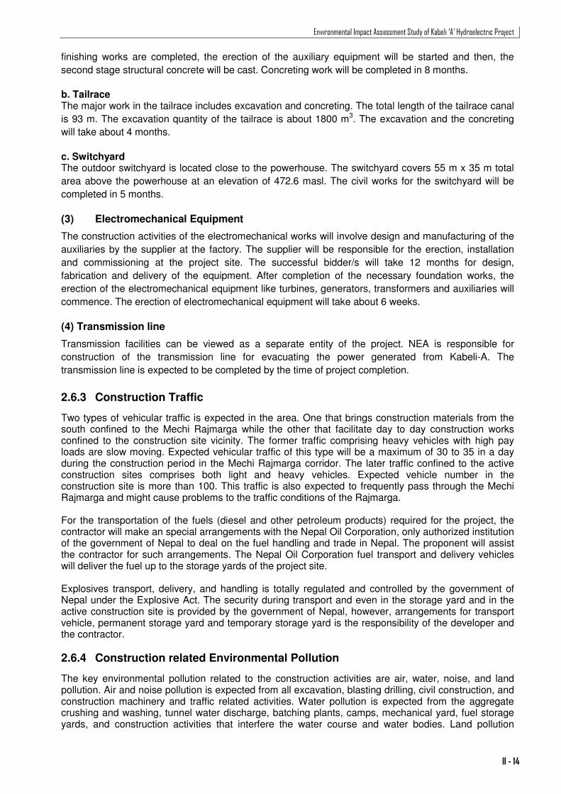
2.7.2 Land Requirement
A total of 47.718 ha of land will be required for the project. Of the total, 22.508 ha is permanent land
while temporary land is 25.21ha (Table 2.2). In terms of land use, 61.10 % is the riverine area including
river beds, river flood plains and elevated banks. Agricultural land required is 35.60 % followed by
3.30% of the forest land including community forests, private forests and leasehold forests. Of the land
use types, only 7.678 ha of agricultural land and 1.57 ha of forest land will be required permanently.
The rest of the permanent land (13.26 ha) required is the riverine area.
Table 2.2: Land Requirement for Various Project Structures and Facilities
SN Name of Project Structure and Facilities
Land Required (Hectare)
Permanent Temporary Total Land Use
Agriculture Forest River Total
A. Project Structures
A.1 Reservoir 9.973 9.973 0.293 0.57 9.11 9.973
A.2 Barrage, Operating Platform, Intake
3.654 3.654 0.954 0.03 2.67 3.654
A.3 Sensor Building 0.01 0.01 0.01 0.01
A.4 Powerhouse and Switchyard 3.922 3.922 2.182 0.27 1.47 3.922
A.5 Penstock Pipe and Surge Shaft
0.70
0.70
0.70
0.70 A.6
Sub- total (A) 18.259 0 18.259 3.429 1.57 13.26 18.259
B Project Facilities
B.1 Access Road to Headwork 0 0 0 0 0
B.2 Quarry Site (Headworks) 3.50 3.50 3.50 3.50
B.3 Quarry Site (Powerhouse) 4.31 4.31 1.01 3.30 4.31
B.4 Spoil/Muck Disposal (Headworks)
4.60 4.60 4.60 4.60
Environmental Impact Assessment Study of Kabeli ‘A’ Hydroelectric Project
II - 16
SN Name of Project Structure and Facilities
Land Required (Hectare)
Permanent Temporary Total Land Use
Agriculture Forest River Total
B.5 Spoil/muck Disposal (Powerhouse)
4.50 4.50 4.50 4.50
B.6 Construction Camp (Headworks)
0.709 2.20 2.909 2.909 2.909
B.7 Construction Camp (Powerhouse)
3.70 3.70 3.70 3.70
B.8 Engineer’s Camp (Powerhouse)
3.54 3.54 3.54 3.54
B.9 Aggregate Crushing, Storage and Batching Plant etc (Headworks)
1.00 1.00 1.00 1.00
B.10 Aggregate Crushing, Storage and Batching Plant etc.(Powerhouse)
1.40 1.40 1.40 1.40
Sub-total (B) 4.249 25.21 29.459 13.559 0 15.90 29.459
Grand Total (A+B) 22.508 25.21 47.718 16.988 1.57 29.16 47.718
Percentage 47.17 52.83 100 35.60 3.30 61.10 100 Source: Field Survey 2010
2.7.3 Human Resources Requirement
Following assumptions were made in the assumption of man power requirement:
� Project construction period of about 4 years and � Wok operation by 8 separate workforce team in different locations
A reasonable estimate based on the consultant’s experience in Middle Marsyangdi Hydroelectric
Project for skilled, semi skilled and unskilled human resources for a project of this size is about 600 to
800 during the peak construction period.
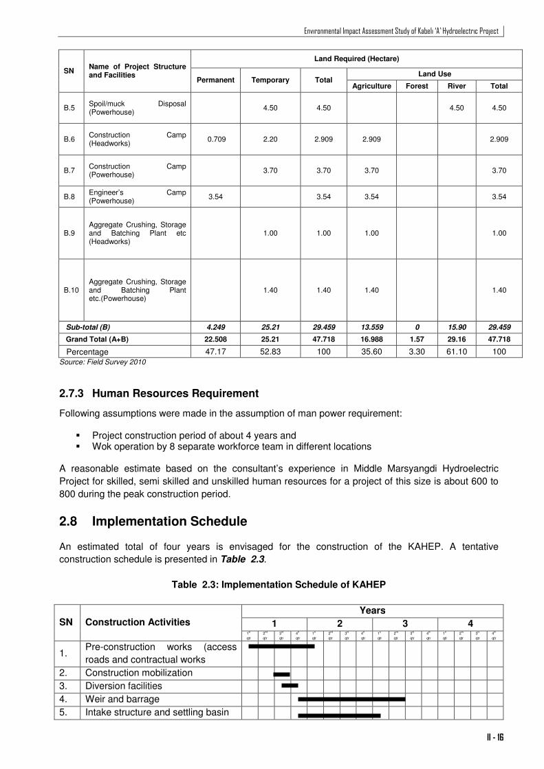
2.8 Implementation Schedule An estimated total of four years is envisaged for the construction of the KAHEP. A tentative
construction schedule is presented in Table 2.3.
Table 2.3: Implementation Schedule of KAHEP
SN Construction Activities
Years
1 2 3 4 1
st
qtr
2nd
qtr
3rd
qtr
4th
qtr
1st
qtr
2nd
qtr
3rd
qtr
4th
qtr
1st
qtr
2nd
qtr
3rd
qtr
4th
qtr
1st
qtr
2nd
qtr
3rd
qtr
4th
qtr
1. Pre-construction works (access
roads and contractual works
2. Construction mobilization
3. Diversion facilities
4. Weir and barrage
5. Intake structure and settling basin

Environmental Impact Assessment Study of Kabeli ‘A’ Hydroelectric Project
II - 17
SN Construction Activities
Years
1 2 3 4 1
st
qtr
2nd
qtr
3rd
qtr
4th
qtr
1st
qtr
2nd
qtr
3rd
qtr
4th
qtr
1st
qtr
2nd
qtr
3rd
qtr
4th
qtr
1st
qtr
2nd
qtr
3rd
qtr
4th
qtr
6. River Training works at headworks
7. Tunnel and surge shaft
8. Powerhouse and tailrace
9. Hydro mechanical parts
10. E & M equipment
11. Switchyard
12. Testing and commissioning
Source:KEL, 2010
2.9 Project Operation Modality The proposed project is a PROR Project. A typical ROR project generates energy at a reduced capacity during the whole day, whereas a PROR project can be designed to operate at full (installed) capacity for a specified number of hours. Considering the available river flow and the riperian water release, this project is designed for two slot peaking mode of 2 hours in the morning and four hours in the evening peaking hours with a reduced capacity. A detailed calculation showing the results for a two slot operation is shown in Annex 2.1, 2.2 and 2.3 and presents the calculations for 2 hour peaking and 4 hour peaking separately. Table 2.4 presents the available mean montly flow, flow that will be diverted for electricity generation and flow released in the Kabeli River downstream barrage for the different months.
Table 2.4: Flow Regulation of the Kabeli River during Operation of the Project
Months Mean monthly flow available m
3/s
Flow diverted for energy generation m
3/s
Flow released from Barrage m
3/s
(10% of annual monthly minimum)
Flow released from tailrace m
3/s
January 9.93 9.12 0.81 37.73 for 5.8 hours a day February 8.25 7.44 0.81 37.73 for 4.7 hours a day March 8.11 7.3 0.81 37.73 for 4.6 hours a day April 11.83 11.02 0.81 37.73 for 7 hours a day May 25.92 25.11 0.81 37.73 for 16 hours a day June 72.42 37.73 35.05 37.73 for 24 hours a day July 142.08 37.73 104.35 37.73 for 24 hours a day August 151.09 37.73 113.36 37.73 for 24 hours a day September 106.31 37.73 68.58 37.73 for 24 hours a day October 49.49 37.73 11.76 37.73 for 24 hours a day November 21.95 21.41 0.81 37.73 for 13.4 hours a day December 13.61 12.80 0.81 37.73 for 8.1 hours a day Source: KEL, 2010
2.10 Project Costs Estimated construction cost of the project is about 66.355 Million US$ equivalent to 5 billion Nepali
rupees at the exchange rate of 75 NRs/$ (Updated Feasibility Report 2010). The above cost
incorporates 75 million NRs. of environmental and resettlement and rehabilitation costs.


