CHAPTER FIVE Weather Hazards of Turbulence, Icing ... · Weather Hazards of Turbulence, Icing,...
34
Weather Hazards of Turbulence, Icing, Ceilings, Visibility, and Ash Clouds 5-1 CHAPTER FIVE Weather Hazards of Turbulence, Icing, Ceilings, Visibility, and Ash Clouds 500. INTRODUCTION This chapter will cover the causes of turbulence, classification of the various categories of turbulence, conditions under which turbulence exists, and recommend flying procedures used when turbulence is encountered. Additionally, it covers the requirements for icing formation, types of icing, and their effects on aircraft flight and aircraft components, including techniques that should be followed for safe flight. Finally, this chapter introduces the student to ceilings and visibility, sky coverage terminology, and the requirements for fog formation and dissipation, plus a synopsis of the aviation hazards of volcanic ash clouds. Turbulence is one of the most unexpected aviation hazards to fly through and also one of the most difficult hazards to forecast. Severe and extreme turbulence has been known to cause extensive structural damage to military aircraft, with lesser intensities resulting in compressor stalls, flameouts, and injury to crewmembers and passengers. From minor bumps to severe mountain wave turbulence, turbulence comes in many forms and is usually worst during the winter months. Turbulence causes an estimated $30 million in annual aviation assets damage. Aircraft icing is another aviation weather hazard. Many aircraft accidents and incidents have been attributed to aircraft icing. In fact, many ice-related mishaps have occurred when the aircraft was not deiced before attempting takeoff. Most of the time, ground deicing and anti- icing procedures adequately handle icing formation. However, there are times when pilots are caught unaware of dangerous ice buildup. Historically, low ceilings and poor visibilities have contributed to many aircraft accidents. Fog, heavy snow, heavy rain, blowing sand, and blowing dust all restrict visibility and can result in low ceilings. Adverse weather conditions causing widespread low ceilings and visibilities can restrict flying operations for days. Since ceiling and visibility is so important to operational flying, it is imperative a pilot understands the strict meanings of the two terms. There are many different kinds of “visibility,” but pilots are usually more concerned with “prevailing visibility.” Ash clouds from volcanic eruptions present a unique hazard to aviation. Though most prudent aviators would choose to keep well clear of any active volcano, certain situations such as evacuations may require the military to operate in close proximity to ash clouds. The corresponding causes of aircraft damage are discussed in the last portion of the chapter. 501. LESSON TOPIC LEARNING OBJECTIVES Terminal Objective: Partially supported by this lesson topic: 2.0 Upon completion of this unit of instruction, student aviators and flight officers will demonstrate knowledge of meteorological theory enabling them to make intelligent decisions when confronted with various weather phenomena and hazards.
-
Upload
vuongkhanh -
Category
Documents
-
view
221 -
download
1
Transcript of CHAPTER FIVE Weather Hazards of Turbulence, Icing ... · Weather Hazards of Turbulence, Icing,...

Weather Hazards of Turbulence, Icing, Ceilings, Visibility, and Ash Clouds 5-1
CHAPTER FIVE
Weather Hazards of Turbulence, Icing, Ceilings, Visibility, and Ash Clouds 500. INTRODUCTION This chapter will cover the causes of turbulence, classification of the various categories of turbulence, conditions under which turbulence exists, and recommend flying procedures used when turbulence is encountered. Additionally, it covers the requirements for icing formation, types of icing, and their effects on aircraft flight and aircraft components, including techniques that should be followed for safe flight. Finally, this chapter introduces the student to ceilings and visibility, sky coverage terminology, and the requirements for fog formation and dissipation, plus a synopsis of the aviation hazards of volcanic ash clouds. Turbulence is one of the most unexpected aviation hazards to fly through and also one of the most difficult hazards to forecast. Severe and extreme turbulence has been known to cause extensive structural damage to military aircraft, with lesser intensities resulting in compressor stalls, flameouts, and injury to crewmembers and passengers. From minor bumps to severe mountain wave turbulence, turbulence comes in many forms and is usually worst during the winter months. Turbulence causes an estimated $30 million in annual aviation assets damage. Aircraft icing is another aviation weather hazard. Many aircraft accidents and incidents have been attributed to aircraft icing. In fact, many ice-related mishaps have occurred when the aircraft was not deiced before attempting takeoff. Most of the time, ground deicing and anti-icing procedures adequately handle icing formation. However, there are times when pilots are caught unaware of dangerous ice buildup. Historically, low ceilings and poor visibilities have contributed to many aircraft accidents. Fog, heavy snow, heavy rain, blowing sand, and blowing dust all restrict visibility and can result in low ceilings. Adverse weather conditions causing widespread low ceilings and visibilities can restrict flying operations for days. Since ceiling and visibility is so important to operational flying, it is imperative a pilot understands the strict meanings of the two terms. There are many different kinds of “visibility,” but pilots are usually more concerned with “prevailing visibility.” Ash clouds from volcanic eruptions present a unique hazard to aviation. Though most prudent aviators would choose to keep well clear of any active volcano, certain situations such as evacuations may require the military to operate in close proximity to ash clouds. The corresponding causes of aircraft damage are discussed in the last portion of the chapter. 501. LESSON TOPIC LEARNING OBJECTIVES Terminal Objective: Partially supported by this lesson topic: 2.0 Upon completion of this unit of instruction, student aviators and flight officers will
demonstrate knowledge of meteorological theory enabling them to make intelligent decisions when confronted with various weather phenomena and hazards.

CHAPTER FIVE AVIATION WEATHER
5-2 Weather Hazards of Turbulence, Icing, Ceilings, Visibility, and Ash Clouds
Enabling Objectives: Completely supported by this lesson topic: 2.48 List the types and intensities of turbulence used in Pilot Reports (PIREPs). 2.49 Define the terms used to report turbulence with respect to time. 2.50 Describe how thermal turbulence develops. 2.51 Describe cloud formations associated with thermal turbulences. 2.52 Describe how mechanical turbulence develops. 2.53 Describe the cloud formations associated with mountain wave turbulence. 2.54 Describe techniques for flight in the vicinity of mountain waves. 2.55 Describe how frontal lifting creates turbulence. 2.56 Describe how jet streams and temperature inversions are examples of wind shear turbulence. 2.57 Describe the recommended procedures for flying through turbulence. 2.58 Describe super cooled water. 2.59 Describe the types of structural icing. 2.60 State the requirements for the formation of structural icing. 2.61 State the temperature range most conducive to structural icing. 2.62 Identify icing conditions associated with fronts. 2.63 Identify the effects and hazards of aircraft icing. 2.64 Describe induction icing and compressor icing. 2.65 Describe ground icing hazards. 2.66 Identify the procedures to minimize or avoid the effects of icing. 2.67 List the types and intensities of icing used in Pilot Reports (PIREPs). 2.68 Define the following terms: visibility, flight visibility, prevailing visibility, slant range
visibility, and runway visual range.

AVIATION WEATHER CHAPTER FIVE
Weather Hazards of Turbulence, Icing, Ceilings, Visibility, and Ash Clouds 5-3
2.69 Define and identify obscuring phenomena. 2.70 List the sky coverage terms that define a ceiling. 2.71 Identify the parameters that define fog. 2.72 Identify the requirements for fog formation. 2.73 Identify the two main types of fog and how they form and dissipate. 2.74 Describe the aviation hazards of ash clouds. 502. REFERENCES 1. Weather for Aircrews, AFH 11-203, Volume 1, Chapters 9, 10, 11, 12, and 16
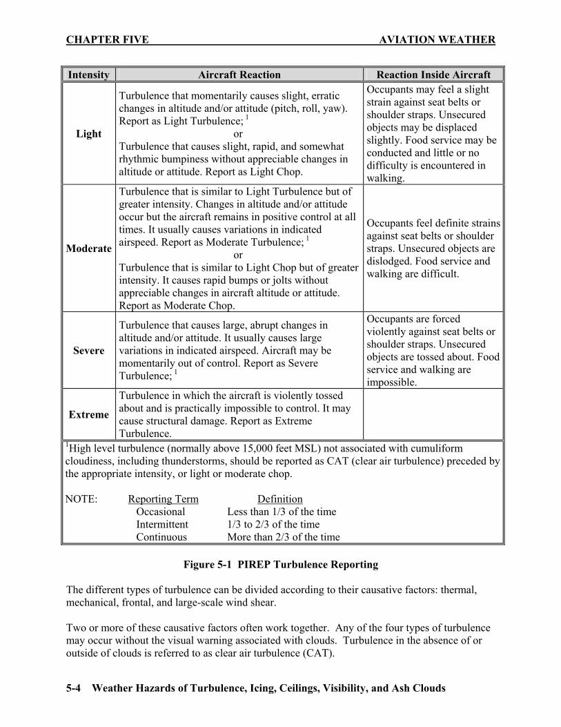
2. DOD Flight Information Publication (En route) Flight Information Handbook, Section C 503. STUDY ASSIGNMENT Review Chapter Five and answer the Study Questions. 504. TURBULENCE DEFINED AND CLASSIFIED Turbulence is any irregular or disturbed flow in the atmosphere producing gusts and/or eddies. Occurrences of turbulence are local in extent and transient in character. Although general forecasts of turbulence are quite good, forecasting precise locations is difficult. Turbulence intensity is classified using a subjective scale. Figure 5-1 contains the four intensity levels and the three time descriptors used by aircrews when giving a Pilot Report (PIREP), which details the in-flight weather. You can see how individual crewmembers of the same aircraft might disagree on the degree of turbulence they encountered. Realize moderate turbulence for a B-52 could be severe or extreme for a T-34.
CHAPTER FIVE AVIATION WEATHER
5-4 Weather Hazards of Turbulence, Icing, Ceilings, Visibility, and Ash Clouds
Intensity Aircraft Reaction Reaction Inside Aircraft
Light
Turbulence that momentarily causes slight, erratic changes in altitude and/or attitude (pitch, roll, yaw). Report as Light Turbulence; 1 or Turbulence that causes slight, rapid, and somewhat rhythmic bumpiness without appreciable changes in altitude or attitude. Report as Light Chop.
Occupants may feel a slight strain against seat belts or shoulder straps. Unsecured objects may be displaced slightly. Food service may be conducted and little or no difficulty is encountered in walking.
Moderate
Turbulence that is similar to Light Turbulence but of greater intensity. Changes in altitude and/or attitude occur but the aircraft remains in positive control at all times. It usually causes variations in indicated airspeed. Report as Moderate Turbulence; 1 or Turbulence that is similar to Light Chop but of greater intensity. It causes rapid bumps or jolts without appreciable changes in aircraft altitude or attitude. Report as Moderate Chop.
Occupants feel definite strains against seat belts or shoulder straps. Unsecured objects are dislodged. Food service and walking are difficult.
Severe
Turbulence that causes large, abrupt changes in altitude and/or attitude. It usually causes large variations in indicated airspeed. Aircraft may be momentarily out of control. Report as Severe Turbulence; 1
Occupants are forced violently against seat belts or shoulder straps. Unsecured objects are tossed about. Food service and walking are impossible.
Extreme
Turbulence in which the aircraft is violently tossed about and is practically impossible to control. It may cause structural damage. Report as Extreme Turbulence.
1High level turbulence (normally above 15,000 feet MSL) not associated with cumuliform cloudiness, including thunderstorms, should be reported as CAT (clear air turbulence) preceded by the appropriate intensity, or light or moderate chop. NOTE: Reporting Term Definition Occasional Less than 1/3 of the time Intermittent 1/3 to 2/3 of the time Continuous More than 2/3 of the time
Figure 5-1 PIREP Turbulence Reporting The different types of turbulence can be divided according to their causative factors: thermal, mechanical, frontal, and large-scale wind shear. Two or more of these causative factors often work together. Any of the four types of turbulence may occur without the visual warning associated with clouds. Turbulence in the absence of or outside of clouds is referred to as clear air turbulence (CAT).
AVIATION WEATHER CHAPTER FIVE
Weather Hazards of Turbulence, Icing, Ceilings, Visibility, and Ash Clouds 5-5
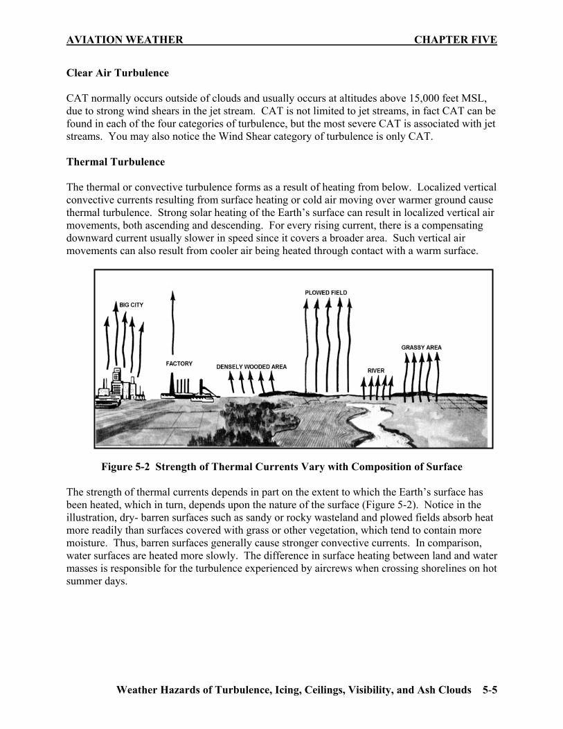
Clear Air Turbulence CAT normally occurs outside of clouds and usually occurs at altitudes above 15,000 feet MSL, due to strong wind shears in the jet stream. CAT is not limited to jet streams, in fact CAT can be found in each of the four categories of turbulence, but the most severe CAT is associated with jet streams. You may also notice the Wind Shear category of turbulence is only CAT. Thermal Turbulence The thermal or convective turbulence forms as a result of heating from below. Localized vertical convective currents resulting from surface heating or cold air moving over warmer ground cause thermal turbulence. Strong solar heating of the Earth’s surface can result in localized vertical air movements, both ascending and descending. For every rising current, there is a compensating downward current usually slower in speed since it covers a broader area. Such vertical air movements can also result from cooler air being heated through contact with a warm surface.
Figure 5-2 Strength of Thermal Currents Vary with Composition of Surface The strength of thermal currents depends in part on the extent to which the Earth’s surface has been heated, which in turn, depends upon the nature of the surface (Figure 5-2). Notice in the illustration, dry- barren surfaces such as sandy or rocky wasteland and plowed fields absorb heat more readily than surfaces covered with grass or other vegetation, which tend to contain more moisture. Thus, barren surfaces generally cause stronger convective currents. In comparison, water surfaces are heated more slowly. The difference in surface heating between land and water masses is responsible for the turbulence experienced by aircrews when crossing shorelines on hot summer days.
CHAPTER FIVE AVIATION WEATHER
5-6 Weather Hazards of Turbulence, Icing, Ceilings, Visibility, and Ash Clouds
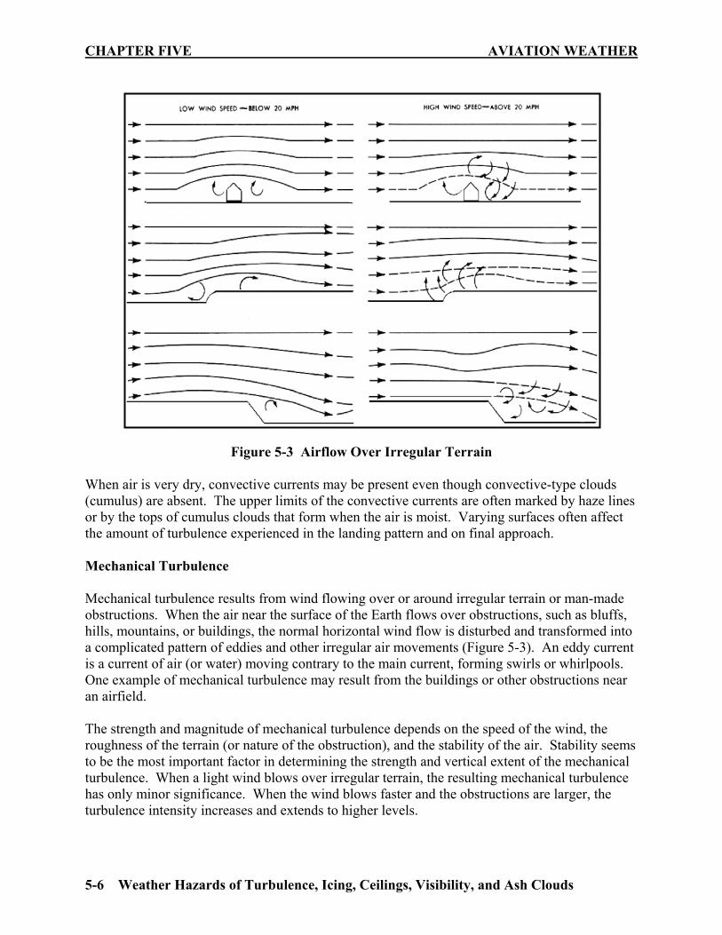
Figure 5-3 Airflow Over Irregular Terrain When air is very dry, convective currents may be present even though convective-type clouds (cumulus) are absent. The upper limits of the convective currents are often marked by haze lines or by the tops of cumulus clouds that form when the air is moist. Varying surfaces often affect the amount of turbulence experienced in the landing pattern and on final approach. Mechanical Turbulence Mechanical turbulence results from wind flowing over or around irregular terrain or man-made obstructions. When the air near the surface of the Earth flows over obstructions, such as bluffs, hills, mountains, or buildings, the normal horizontal wind flow is disturbed and transformed into a complicated pattern of eddies and other irregular air movements (Figure 5-3). An eddy current is a current of air (or water) moving contrary to the main current, forming swirls or whirlpools. One example of mechanical turbulence may result from the buildings or other obstructions near an airfield. The strength and magnitude of mechanical turbulence depends on the speed of the wind, the roughness of the terrain (or nature of the obstruction), and the stability of the air. Stability seems to be the most important factor in determining the strength and vertical extent of the mechanical turbulence. When a light wind blows over irregular terrain, the resulting mechanical turbulence has only minor significance. When the wind blows faster and the obstructions are larger, the turbulence intensity increases and extends to higher levels.

AVIATION WEATHER CHAPTER FIVE
Weather Hazards of Turbulence, Icing, Ceilings, Visibility, and Ash Clouds 5-7
Mountain Wave Turbulence When strong winds blow approximately perpendicular to a mountain range, the resulting turbulence can be severe. Associated areas of steady updrafts and downdrafts may extend to heights from 2 to 20 times the height of the mountain peaks. When the air is stable, large waves tend to form on the lee side of the mountains and extend up to the lower stratosphere for a distance of up to 300 miles or more downwind.
Figure 5-4 Mountain Wave Turbulence These are referred to as standing waves or mountain waves, and may or may not be accompanied by turbulence (Figure 5-4). Pilots, especially glider pilots, have reported the flow in these waves is often remarkably smooth. Others have reported severe turbulence. Even though mountain wave turbulence may be present, when the airflow begins to move up the windward side of the mountain, it is usually fairly smooth as the orographic lifting imparts the vertical component to the motion of the air. The wind speed gradually increases, reaching a maximum near the peak of the mountain. Past the peak, the air naturally flows down the leeward side, completing one cycle of oscillation and setting up the standing wave pattern of the mountain wave turbulence. Downwind, perhaps five to ten miles from the peak, the airflow begins to ascend again, where the rotor or lenticular clouds may appear. Additional waves, generally less intense than the primary wave, may form farther downwind. Note in Figures 5-4 and 5-5 the mountains are on the left and the wind is flowing from left to right. While lenticular, cap, and rotor clouds are usually present to warn aircrews of mountain wave activity, it is possible for wave action to take place when the air is too dry to form clouds, producing CAT. Still, cloud forms particular to wave action provide the best means of identifying possible turbulence, aside from weather forecasts and PIREPs. Although the lenticular clouds in Figure 5-5 are smooth in contour, they may be quite ragged when the airflow

CHAPTER FIVE AVIATION WEATHER
5-8 Weather Hazards of Turbulence, Icing, Ceilings, Visibility, and Ash Clouds
at that level is turbulent. These clouds may occur singularly or in layers at heights usually above 20,000 feet. The rotor cloud forms at a lower level and is generally found at about the same height as the mountain ridge. The cap cloud usually obscures both sides of the mountain peak. The lenticular clouds (Figure 5-5), like the rotor and cap clouds, are stationary in position, even though the wind flows through them.
Figure 5-5 Lenticular Clouds The pilot is concerned, for the most part, with the first wave because of its more intense activity and proximity to the high mountainous terrain. Extreme turbulence is usually found at low levels on the leeward side of the mountain in or near the rotor and cap clouds when the winds are 50 knots or greater at the mountaintop. With these wind conditions, severe turbulence can frequently be found to exist from the surface to the tropopause and 150 miles downwind. Moderate turbulence can be experienced often as far as 300 miles downwind under those same conditions. When the winds are less than 50 knots at mountain peak level, a lesser degree of turbulence may be experienced. Mountain wave turbulence is dangerous in the vicinity of the rotor clouds and to the leeward side of the mountain peaks. The cap cloud must always be avoided because of the turbulence and the concealed mountain peaks. Apply the following techniques when mountain wave turbulence has been forecasted: 1. Avoid the turbulence, if possible, by flying around the areas where wave conditions exist. If this is not feasible, fly at a level at least 50% higher than the height of the mountain range. This procedure will not keep the aircraft out of turbulence, but provides a margin of safety if a strong downdraft is encountered.
AVIATION WEATHER CHAPTER FIVE
Weather Hazards of Turbulence, Icing, Ceilings, Visibility, and Ash Clouds 5-9
2. Avoid the rotor, lenticular, and the cap clouds since they contain intense turbulence and strong updrafts and downdrafts.
3. Approach the mountain range at a 45° angle, so a quick turn can be made away from the ridge if a severe downdraft is encountered.
4. Avoid the leeward side of mountain ranges, where strong downdrafts may exist, until certain turbulence is not a factor.
5. Do not place too much confidence in pressure altimeter readings near mountain peaks. They may indicate altitudes more than 2500 feet higher than the true altitude.
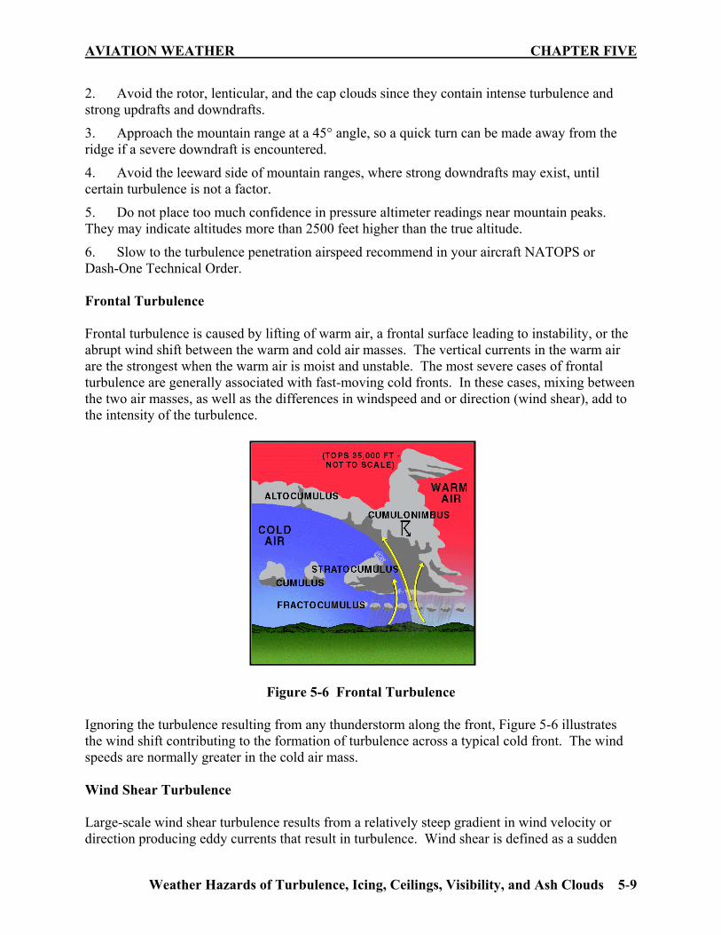
6. Slow to the turbulence penetration airspeed recommend in your aircraft NATOPS or Dash-One Technical Order. Frontal Turbulence Frontal turbulence is caused by lifting of warm air, a frontal surface leading to instability, or the abrupt wind shift between the warm and cold air masses. The vertical currents in the warm air are the strongest when the warm air is moist and unstable. The most severe cases of frontal turbulence are generally associated with fast-moving cold fronts. In these cases, mixing between the two air masses, as well as the differences in windspeed and or direction (wind shear), add to the intensity of the turbulence.
Figure 5-6 Frontal Turbulence Ignoring the turbulence resulting from any thunderstorm along the front, Figure 5-6 illustrates the wind shift contributing to the formation of turbulence across a typical cold front. The wind speeds are normally greater in the cold air mass. Wind Shear Turbulence Large-scale wind shear turbulence results from a relatively steep gradient in wind velocity or direction producing eddy currents that result in turbulence. Wind shear is defined as a sudden

CHAPTER FIVE AVIATION WEATHER
5-10 Weather Hazards of Turbulence, Icing, Ceilings, Visibility, and Ash Clouds
change in windspeed or direction over a short distance in the atmosphere. The greater the change in windspeed and/or direction in a given area, the more severe the turbulence will be. These turbulent wind shear flight conditions are frequently encountered in the vicinity of the jet stream, where large shears in both the horizontal and vertical planes are found, as well as in association with land and sea breezes, fronts, inversions, and thunderstorms. Strong wind shear can abruptly distort the smooth flow of wind, creating rapid changes in aircraft performance. Jet stream turbulence is described in Chapter Two as one of the major sources of wind shear turbulence, which can sometime reach speeds of over 250 knots (Figure 5-7). The highest wind speeds and probable associated turbulence is found about 5000 feet below the tropical tropopause and closer to the tropopause in the polar regions. The rapid change of wind speed within a short distance of the jet core is particularly significant. The vertical shear is generally close to the same intensity both above and below the core, and it may be many times stronger than the horizontal shear. The horizontal shear on the cold air side of the core is stronger than on the warm air side. Thus, if it is desired to exit jet stream turbulence, a turn to the south should result in smoother air. Additionally, a climb or descent to a different flight level should help, as jet stream turbulence often occurs in patches averaging 2000 feet deep, 20 miles wide, and 50 miles long. If changing altitude, watch the outside air temperature for a minute or two to determine the best way to exit the CAT quickly. If the temperature is rising, climb; if the temperature is falling, descend. This maneuver will prevent following the sloping tropopause or frontal surface and thereby staying in the turbulent area. If the temperature remains the same, either climb or descend.
Figure 5-7 Jet Stream Diagram Temperature Inversions Recall from Chapter One the lapse rate where temperature increases with altitude, there is a temperature inversion. Even though this produces a stable atmosphere, inversions can cause turbulence at the boundary between the inversion layer and the surrounding atmosphere. The resulting turbulence can often cause a loss of lift and airspeed near the ground, such as when a headwind becomes a tailwind, creating a decreasing-performance wind shear. It is important to know how to recognize and anticipate an inversion in flight so you can prepare and take precautions to minimize the effects. If you are caught unaware, the loss of lift can be catastrophic because of your proximity to the ground. Inversions often develop near the ground

AVIATION WEATHER CHAPTER FIVE
Weather Hazards of Turbulence, Icing, Ceilings, Visibility, and Ash Clouds 5-11
on clear, cool nights when the winds are light and the air is stable. If the winds just above the inversion grow relatively strong, wind shear turbulence can result. Figure 5-7 shows a wind shear zone and the turbulence that developed between the calm air and stronger winds above the inversion. When taking off or landing in near-calm surface winds under clear skies within a few hours of sunrise, watch for a temperature inversion near the surface. If the wind at 2000 to 4000 feet AGL is 25 knots or more, expect a shear zone at the inversion. To prepare yourself, allow a margin of airspeed above normal climb or approach speed if turbulence or a sudden change in wind speed occurs in order to counteract the effects of a diminished headwind or increased tailwind at and below the inversion.
Figure 5-8 Wind Shear Associated With a Temperature Inversion Turbulence Associated with Thunderstorms The strongest turbulence within cumulonimbus clouds occurs with the shear between the updrafts and downdrafts. Outside the clouds, wind shear turbulence has been encountered several thousand feet above and 20 miles laterally from a severe storm. Severe turbulence can be encountered in the anvil 15 to 30 miles downwind. The storm cloud is only the visible portion of a turbulent system whose updrafts and downdrafts often extend outside the storm. Flight Techniques For Turbulence If you cannot avoid flying in turbulence, recommend the following procedures: 1. Establish and maintain thrust settings consistent with turbulent air penetration airspeed and aircraft attitude. Severe turbulence may cause large and rapid variations in indicated airspeed. Do not chase airspeed.
2. Trim the aircraft for level flight at the recommended turbulent air penetration airspeed. Do not change trim after the proper attitude has been established.
CHAPTER FIVE AVIATION WEATHER
5-12 Weather Hazards of Turbulence, Icing, Ceilings, Visibility, and Ash Clouds
3. The key to flying through turbulence is proper attitude control. Both pitch and bank should be controlled by reference to the attitude gyro indicator. Extreme gusts may cause large changes in pitch or bank. To avoid overstressing the aircraft, do not make abrupt control inputs. Use moderate control inputs to reestablish the desired attitude.
4. Severe vertical gusts may cause appreciable altitude deviations. Allow altitude to vary. Sacrifice altitude to maintain desired attitude. Do not chase the altimeter. 505. AIRCRAFT ICING
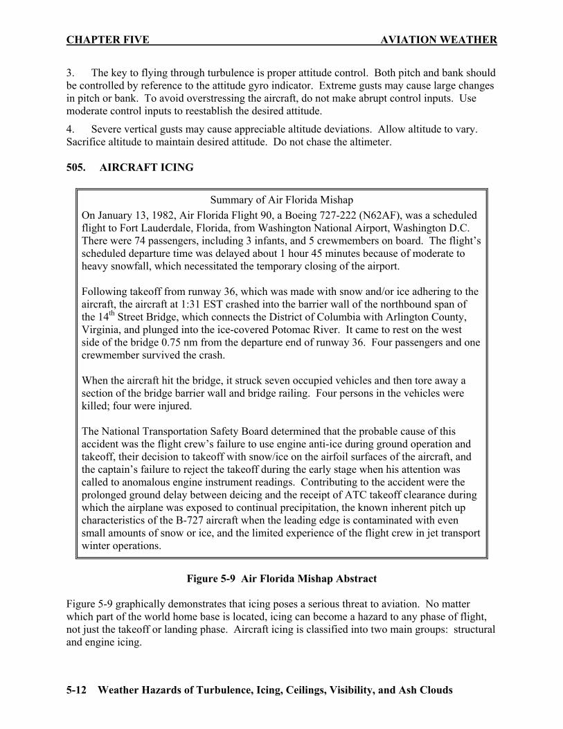
Figure 5-9 Air Florida Mishap Abstract
Figure 5-9 graphically demonstrates that icing poses a serious threat to aviation. No matter which part of the world home base is located, icing can become a hazard to any phase of flight, not just the takeoff or landing phase. Aircraft icing is classified into two main groups: structural and engine icing.
Summary of Air Florida Mishap On January 13, 1982, Air Florida Flight 90, a Boeing 727-222 (N62AF), was a scheduled flight to Fort Lauderdale, Florida, from Washington National Airport, Washington D.C. There were 74 passengers, including 3 infants, and 5 crewmembers on board. The flight’s scheduled departure time was delayed about 1 hour 45 minutes because of moderate to heavy snowfall, which necessitated the temporary closing of the airport. Following takeoff from runway 36, which was made with snow and/or ice adhering to the aircraft, the aircraft at 1:31 EST crashed into the barrier wall of the northbound span of the 14th Street Bridge, which connects the District of Columbia with Arlington County, Virginia, and plunged into the ice-covered Potomac River. It came to rest on the west side of the bridge 0.75 nm from the departure end of runway 36. Four passengers and one crewmember survived the crash. When the aircraft hit the bridge, it struck seven occupied vehicles and then tore away a section of the bridge barrier wall and bridge railing. Four persons in the vehicles were killed; four were injured. The National Transportation Safety Board determined that the probable cause of this accident was the flight crew’s failure to use engine anti-ice during ground operation and takeoff, their decision to takeoff with snow/ice on the airfoil surfaces of the aircraft, and the captain’s failure to reject the takeoff during the early stage when his attention was called to anomalous engine instrument readings. Contributing to the accident were the prolonged ground delay between deicing and the receipt of ATC takeoff clearance during which the airplane was exposed to continual precipitation, the known inherent pitch up characteristics of the B-727 aircraft when the leading edge is contaminated with even small amounts of snow or ice, and the limited experience of the flight crew in jet transport winter operations.

AVIATION WEATHER CHAPTER FIVE
Weather Hazards of Turbulence, Icing, Ceilings, Visibility, and Ash Clouds 5-13
Structural icing forms on the external structure of an aircraft. Structural ice forms on the wings, fuselage, antennas, pitot tubes, rotor blades, and propellers. Significant structural icing on an aircraft can cause control problems and dangerous performance degradation. The types of structural icing are clear, rime, mixed, and frost. Engine icing occurs when ice forms on the induction or compressor sections of an engine, reducing its performance. Icing Requirements There are two requirements for the formation of aircraft icing. First, the atmosphere must have super-cooled visible water droplets. Second, the free air temperature and the aircraft’s surface temperature must be below freezing. Clouds are the most common form of visible liquid water and super-cooled water is liquid water found at air temperatures below freezing. When super-cooled droplets strike an exposed object, such as a wing, the impact induces freezing and results in aircraft icing. Therefore, when penetrating a cloud at subzero temperatures, icing should be expected. Frozen precipitation in solid form (hail, snow grains, ice pellets) does not cause structural icing. Super-cooled water forms because, unlike bulk water, water droplets in the free air do not freeze at 0°C. Instead, their freezing temperature varies from –10 to –40 degrees C: the smaller the droplets, the lower the freezing point. As a general rule, serious icing is rare in clouds with temperatures below –20°C since these clouds are almost completely composed of ice crystals. However, icing is possible in any cloud when the temperature is 0°C or below. Structural Icing Conditions Clear icing normally occurs at temperatures between 0 and –10 degrees C, where water droplets are large because of unstable air, such as in cumulus clouds and in areas of freezing rain or drizzle. Instead of freezing instantly upon contact with the aircraft’s surface, these large water droplets move along with the airflow, freeze gradually, and form a solid layer of ice. This layer of clear ice can cover a large portion of the wing surface and is difficult to break off. Clear icing is the most severe form of icing because it builds up fast, can freeze the flight controls, and disrupts airflow over the wings. Rime icing is rough, opaque, milky white in appearance and most likely to occur at temperatures of –10 to –20 °C. It is more dense and harder than frost, but lighter, softer, and less transparent than clear ice. Rime ice occurs in stable conditions, clouds where the water droplets are small and freeze instantaneously, such as stratiform clouds and the upper portions of cumulus clouds. It is brittle and fairly easy to break off. Rime ice does not normally spread over an aircraft surface, but protrudes forward into the air stream along the leading edges of airfoils. Mixed icing is a combination of clear ice and rime ice, occurring where both large and small water droplets are present, normally at temperatures of –8 to –15 degrees C. Because mixed icing is a combination of large and small water droplets, it takes on the appearance of both rime

CHAPTER FIVE AVIATION WEATHER
5-14 Weather Hazards of Turbulence, Icing, Ceilings, Visibility, and Ash Clouds
and clear icing. It is lumpy, like rime ice, but also hard and dense, like clear ice. The most frequent type of icing encountered is usually a form of mixed icing. Frost is a thin layer of crystalline ice that forms on exposed surfaces. It normally occurs on clear, calm wind nights when the air temperature and dew point are below freezing. Frost also forms in flight when a cold aircraft descends from a zone of freezing temperatures into high relative humidity. The moist air is chilled suddenly to below freezing temperatures by contact with the cold surfaces of the aircraft, and deposition occurs. Frost, like other forms of icing, disrupts the smooth boundary layer flow over airfoils, and thus increases drag, causes a loss of lift, and increases stall speed. Though it is unlikely to add considerable weight to an aircraft, any amount of frost is hazardous and must be removed prior to takeoff. Aircrews should anticipate and plan for some type of icing on every flight conducted in below freezing temperatures and should be familiar with the icing generally associated with different atmospheric conditions, as discussed in the next section. Frontal Icing Conditions Cold fronts and squall lines generally have a narrow band of both weather and icing. The associated clouds will be cumuliform. The icing zone will be about 10,000 feet thick, 100 miles wide, and the icing will be predominantly clear, accumulating rapidly. Warm fronts and stationary fronts generally have a much wider band of weather and icing, reflecting the size of the warm frontal zone. The icing will be found mainly inside stratiform clouds, accumulating at a relatively low rate, due to the smaller size of the super-cooled water droplets. The vertical depth of the icing zone will generally be about 3000 to 4000 feet thick, possibly up to 10,000 feet. The type of icing will be predominantly rime, but may also contain mixed icing. The most critical icing (rain or drizzle) area is where water is falling from warm air above to a flight level temperature below freezing. In this case, severe clear ice would be encountered below the cloud layer and the evasive action is to climb to an altitude where the temperature is above freezing. Occluded fronts often produce icing covering a very widespread area, containing both stratiform and cumuliform type clouds. The depth of the icing zone will often be 20,000 feet, approximately double the depth of icing zones with other type fronts. The types of icing will be clear, mixed, and rime, with a very rapid and heavy rate of accumulation. 506. EFFECTS AND HAZARDS OF STRUCTURAL ICING The most hazardous aspect of structural icing is its aerodynamic effects. The presence of ice on an aircraft decreases lift, thrust, and range, and increases drag, weight, fuel consumption, and stall speed. The added weight with reduced lift and thrust can be a dangerous combination (Figure 5-10). Ice can alter the shape of an airfoil, changing the angle of attack at which the aircraft stalls and therefore increasing the stall speed. Ice reduces lift and increases drag on an

AVIATION WEATHER CHAPTER FIVE
Weather Hazards of Turbulence, Icing, Ceilings, Visibility, and Ash Clouds 5-15
airfoil. Ice thickness is not the only factor determining the effect of icing. Location, roughness, and shape are important, too. For example, a half-inch high ridge of ice on the upper surface of the airfoil at 4% chord reduces maximum lift by over 50%. Yet, the same ridge of ice at 50% chord decreases maximum lift by only 15%. On another airfoil, a distributed sandpaper-like roughness on the leading edge of the wing may decrease lift by 35%. Along with this decrease in lift, it is obvious parasite drag will significantly increase. The buildup of ice on various structural parts of the aircraft can result in vibration, causing added stress to those parts. This is especially true in the case of propellers and rotors, which are delicately balanced. Even a small amount of ice, if not distributed evenly, can cause great stress on the propeller and engine mounts.
Figure 5-10 Cumulative Effects of Icing Icing is not restricted to airfoils and other external structure. Engines, fuel, and instruments may also be affected by ice formation. Ice associated with freezing rain or drizzle can accumulate beyond the limits of an ice protection system. If you encounter any type of freezing rain or drizzle, the best course of action is to leave the area. Structural icing can block the pitot tube (Figure 5-11) and static ports. This can cause a pilot to either lose or receive erroneous indications from various instruments such as the airspeed indicator, VSI, and altimeter. For example, if the pitot tube becomes blocked with ice, the “total pressure” input to the system remains constant. Therefore, during a descent, as the “static pressure” input to the system increases, the airspeed indicator gives an erroneous indication of decreasing airspeed. The opposite would be true during a climb.
THRUST & RANGEDECREASE
LIFT DECREASES
WEIGHT INCREASES
DRAG & FUEL CONSUMPTION
INCREASE
STALL SPEEDINCREASES

CHAPTER FIVE AVIATION WEATHER
5-16 Weather Hazards of Turbulence, Icing, Ceilings, Visibility, and Ash Clouds
Figure 5-11 Pitot Tube Icing During flight, it can be difficult to detect ice on areas such as the empennage that may be impossible to see. Cues that signal the potential for icing include the following:
1. Ice on windshield wiper arms or projections such as engine drain tubes, pitot tubes, engine inlet lips, or propeller spinners,
2. decreasing airspeed with constant power and altitude, and
3. ice detector annunciation. Icing on rotary wing aircraft is related to those involving wings and propellers. Ice formation on the helicopter main rotor system or antitorque rotor system may produce serious vibration, loss of efficiency or control, and can significantly deteriorate the available RPM to a level where safe landing cannot be assured. In fact, a 3/16-inch (4.8-mm) coating of ice is sufficient to prevent some helicopters from maintaining flight in a hover. 507. OTHER TYPES OF AIRCRAFT ICING Induction icing – in flights through clouds containing super-cooled water droplets, air intake duct icing is similar to wing icing. However, the ducts may ice when skies are clear and temperatures are above freezing. The reduced pressure that exists at the intake lowers the temperature to the point that condensation and/or deposition take place, resulting in the formation of ice. The degree of temperature decrease varies considerably with different types of engines. However, if the free air temperature is 10°C or less (especially near the freezing point) and the relative humidity is high, the possibility of induction icing exists. Ingestion of ice shed ahead of the compressor inlet may cause severe foreign object damage to the engine. Compressor icing – ice forming on compressor inlet screens and compressor inlet guide vanes will restrict the flow of inlet air, eventually causing engine flameout. The reduction in airflow is noticeable through a loss of thrust and a rapid rise in exhaust gas temperature. As the airflow decreases, the fuel-air ratio increases, which in turn raises the temperature of the gases going to the turbine. The fuel control attempts to correct any loss in engine RPM by adding more fuel, which merely aggravates the condition. Ice build-up on inlet screens sufficient to cause turbine failure can occur in less than one minute under severe conditions.

AVIATION WEATHER CHAPTER FIVE
Weather Hazards of Turbulence, Icing, Ceilings, Visibility, and Ash Clouds 5-17
Ground icing hazards – we have already stressed the importance of removing all icing and frost from an aircraft prior to takeoff. De-icing itself, however, can also be a hazard. De-icing fluids (discussed in the next section) are highly corrosive to internal aircraft and engine parts. Thus, it is imperative de-icing crews understand the particular requirements for your type of aircraft. Additionally, taxiing through mud, water or slush on ramps and runways can create a covering of ice that can hamper the movement of flaps, control surfaces, and the landing gear mechanism. Ice and snow on runways are conditions that affect braking action of aircraft. Braking action varies widely with aircraft type and weight. Therefore, pilots must be aware of the limits to their aircraft’s braking capabilities. 508. MINIMIZING OR AVOIDING ICING HAZARDS Flight Path Options In coping with an icing hazard in flight, a pilot usually has two alternatives. First, the pilot can climb to the colder temperatures where the precipitation will be frozen and therefore not an icing hazard. Second, the pilot can descend to an altitude where the air temperatures are well above freezing (Figure 5-12). However, if encountering clear icing in the freezing precipitation below the clouds of a warm front, the aircraft is most likely in the cold air ahead of the warm front. In this case, the best alternative may be to climb to warmer temperatures, across the frontal boundary, as the freezing precipitation may extend all the way to ground level.
Figure 5-12 Options to Escape Icing Anti-Icing and Deicing Equipment Deicing equipment eliminates or removes ice already accumulated on the aircraft. Anti-icing equipment prevents the accumulation of ice on specific aircraft surfaces. Most military aircraft

CHAPTER FIVE AVIATION WEATHER
5-18 Weather Hazards of Turbulence, Icing, Ceilings, Visibility, and Ash Clouds
are equipped with anti-icing and/or deicing equipment. There are three common methods for preventing and/or eliminating ice buildup: mechanical, fluids, and heat. The mechanical method uses deicing boots, which are rubber bladders installed on the leading edges of lift producing surfaces. Compressed air cycles through these rubber boots causing them to alternately inflate and deflate, thus cracking accumulated ice and allowing the air stream to peel it away. Anti-icing fluids are freezing point depressants and are pumped through small holes in the wing’s leading edge. This fluid coats the wing, preventing ice from forming on the wing’s surface. Additionally, ground crews use deicing fluids to remove and prevent ice buildup before takeoff. Heat application capability to wings, props, tail surfaces, or engine intakes is installed in most aircraft. Systems of this nature can be designed for either anti-icing or deicing purposes. Critical areas can be heated electrically or by hot air bled from the engine’s compressor section. Recommended Precautions Keep these precautions in mind when flying in the vicinity of icing conditions: 1. Do not fly into areas of known or forecast icing conditions.
2. Avoid flying in clouds with temperatures from 0 to –20 degrees C.
3. Do not fly through rain showers or wet snow with temperatures near freezing.
4. Avoid low clouds above mountain ridges or crests. Expect the heaviest icing in clouds around 5000 feet above the mountaintops.
5. Do not make steep turns with ice on the airplane due to increased stall speeds.
6. Avoid high angles of attack when ice has formed on the aircraft since the aircraft is closer to stall speed in these maneuvers.
7. Under icing conditions, increased drag and additional power required increases fuel consumption.
8. Change altitude to temperatures above freezing or colder than -20 °C. An altitude change also may take you out of clouds.
9. In freezing rain, climb to temperatures above freezing, since it will always be warmer at some higher altitude. Do not delay your climb; ice can accumulate quickly. If you are going to descend, you must know the temperature and terrain below.
10. Do not fly parallel to a front while encountering icing conditions.
11. Avoid icing conditions as much as possible in the terminal phase of flight due to reduced airspeeds.
12. Expect to use more power on final approach when experiencing structural icing.
13. Always remove ice or frost from airfoils before attempting takeoff.

AVIATION WEATHER CHAPTER FIVE
Weather Hazards of Turbulence, Icing, Ceilings, Visibility, and Ash Clouds 5-19
Icing Intensities And PIREPS Weather personnel cannot generally observe icing; they must rely on PIREPs. When flying during icing conditions, pilots should report these conditions as indicated in Figure 5-13. However, forecasters attempt to forecast the maximum intensity of icing that may be encountered during a flight, not necessarily the intensity of icing encountered by a particular aircraft. It becomes the pilot’s responsibility to make certain a complete weather briefing is obtained, to include the information for safe completion of the flight.
Figure 5-13 Icing Reporting Criteria
Intensity Airframe Ice Accumulation Pilot Report
Trace Ice becomes perceptible. Rate of accumulation slightly greater than rate of sublimation. It is not hazardous even though deicing/anti-icing equipment is not used, unless encountered for an extended period of time--over one hour.
Light The rate of accumulation may create a problem if flight is prolonged in this environment (over one hour). Occasional use of deicing/anti-icing equipment removes/prevents accumulation. It does not present a problem if the deicing/anti-icing equipment is used.
Moderate The rate of accumulation is such that even short encounters become potentially hazardous and use of deicing/anti-icing equipment or diversion is necessary.
Severe The rate of accumulation is such that deicing/anti-icing equipment fails to reduce or control the hazard. Immediate diversion is necessary.
Aircraft identification, location, time (GMT), altitude (MSL), type aircraft, sky cover, visibility & weather, temperature, wind, turbulence, icing, remarks.
Example of PIREP transmission:
"Pensacola METRO, Rocket 501, holding 20 miles south of Navy Pensacola, at 2100Z and one-six thousand feet, single T-39 Sabreliner, we’re IFR in stratus clouds, temperature –15°C, winds 330 at 25, no turbulence, Light Rime Icing, flying 200 knots indicated.
Icing may be rime, clear, or mixed:
Rime ice – Rough milky opaque ice formed by the instantaneous freezing of small super-cooled water droplets.
Clear ice – A glossy, clear or translucent ice formed by the relatively slow freezing of large super-cooled water droplets.
Mixed ice – A combination of rime and clear ice.

CHAPTER FIVE AVIATION WEATHER
5-20 Weather Hazards of Turbulence, Icing, Ceilings, Visibility, and Ash Clouds
509. VISIBILITY DEFINITIONS Visibility is important to all aviators since it plays an essential role in takeoffs, approaches, and landings. Visibility is defined as the ability to see and identify prominent unlighted objects by day and prominent lighted objects at night, and is expressed in statute miles, hundreds of feet, or meters. There are several particular methods of reporting visibility, some of which are defined below. Flight visibility is the average forward horizontal distance, measured in statute miles from the cockpit of an aircraft in flight, at which a pilot can see and identify prominent unlighted objects by day and prominent lighted objects at night. Prevailing visibility is the greatest horizontal visibility, measured in statute miles, equaled or exceeded throughout at least half the horizon circle, which need not be continuous. Figure 5-14 illustrates how prevailing visibility is determined. The center of the circles depict the observation point and the edge of the circles represent a distance of three miles, the furthest that prominent objects may be seen and identified. In the left depiction, the maximum visibility common to half or more of the horizon circle is three miles, so the prevailing visibility is three miles. If a bank of fog were to roll in to the airfield, as in the right depiction, visibility toward the east would be reduced. However, the observer can still see three miles throughout at least 180° of view, so the prevailing visibility is still three miles. Look at the visibility for each of the runways, and notice how the actual visibility may vary significantly from the prevailing visibility.
Figure 5-14 Prevailing Visibility Determination Slant Range Visibility is the distance on final approach when the runway environment is in sight. This is probably the most vital weather information needed during a final approach in questionable weather. Unfortunately, slant rage visibility is not often provided because of great difficulty in estimating or measuring it from the ground. Runway Visual Range (RVR) provides the best indication of the slant range visibility. However, other weather information such as precipitation and prevailing visibility help indicate slant range visibility.

AVIATION WEATHER CHAPTER FIVE
Weather Hazards of Turbulence, Icing, Ceilings, Visibility, and Ash Clouds 5-21
RVR is the horizontal distance, expressed in hundreds of feet or meters, a pilot will see by looking down the runway from the approach end. For takeoff and landing under IFR, prevailing visibility is not as important as the visibility within the runway environment. Surface vs Flight Visibility RVR and prevailing visibility are horizontal visibilities near the Earth’s surface. They may be quite different from the vertical visibility when looking down at the ground from an aircraft in flight. For example, surface visibility may be seriously reduced by fog or blowing snow, yet only a slight reduction in visibility is apparent when viewed from above the field. In Figure 5-15, the airfield may be seen relatively clearly from above the fog. When descending to the level of the fog, however, the airfield may disappear from sight. In another situation, flying into the setting sun on a hazy day may reduce flight visibility to values less than the surface visibility. When given the surface visibility, learn to anticipate what your flight visibility is likely to be. It may vary, depending on other weather conditions present.
Figure 5-15 Surface vs Flight Visibility Obscuring Phenomena Obscuring phenomena are any collection of particles reducing horizontal visibility to less than six miles. They may be either surface based or aloft. Examples include fog, haze, smoke, volcanic ash, and blowing spray, to name a few. Haze produces a bluish color when viewed against the ground. Although haze may occur at any level in the troposphere, it is more common in the lower few thousand feet. Haze is associated
Prevailing Visibility1/2 Mile Due to Fog
Airfield
Verti
cal V
isib
ility
Slant Range Visibility

CHAPTER FIVE AVIATION WEATHER
5-22 Weather Hazards of Turbulence, Icing, Ceilings, Visibility, and Ash Clouds
with a stable atmosphere. The top of a haze layer, which is usually confined by a low level inversion, has the appearance of a horizon when viewed from above the layer. In this case, the haze may completely obscure the ground in all directions except the vertical. Dense haze may reduce visibility to less than three miles, with slant range visibility generally less than surface visibility. Visibility in haze is lower when looking toward the Sun than away from it. Smoke causes the sunrise and sunset to appear very red. Smoke reduces visibility in a manner similar to haze. Smoke from forest fires is often concentrated in layers aloft with good visibility beneath. Smoke may be a major concern near industrial areas. Smoke from forest fires has been carried great distances at high altitudes. Aircrews flying at these altitudes may encounter dense smoke, although the lower altitudes are clear. Rain and drizzle are precipitation in liquid form that can reduce visibility. Precipitation also reduces visibility as it streams across a windshield or canopy. Drizzle is a feature of stable air with the likely presence of fog or smog. Therefore, drizzle may result in extremely poor visibility. Approaches and the ensuing transition to visual flight can be very hazardous since moderate to heavy rain conditions can seriously affect the recognition of visual cues. Night approaches in these conditions can be even more critical as you may be distracted by the aircraft’s flashing strobes or sequenced flashing runway lights. Snow affects visibility much more than rain or drizzle and can easily reduce visibility to less than one mile. It is often difficult to see snow falling ahead of you; you may enter the snow unexpectedly. Blowing snow is fine dry snow easily lifted by the wind up to 300 feet AGL, depending on wind strength and air stability. During or after a fresh snowfall with brisk winds, surface visibility may be reduced to less than 1/2 mile. Blowing snow is accompanied by many of the same hazards as rain, such as turbulence (creating difficulties in reading flight instruments) and obscured visual cues (a lack of visual cues for runway identification during the visual portion of the approach). The approach and runway lights will provide some identification of the runway environment; however, runway markings may be lost in the whiteness. Therefore, depth perception will be difficult, requiring more emphasis on instruments. Dust and sand form when strong winds combined with unstable air and loose dry soil can blow dust or sand into the air. Dust is finer than sand and strong winds may lift the dust to considerable heights. Sand will usually be limited in altitude to 50 or 100 feet. In severe conditions, visibility can be near zero. Blowing dust is common behind cold fronts moving rapidly across prairies in early spring before a cover of vegetation has appeared. This effect may cause blowing dust conditions and reduced visibilities over a wide area. 510. SKY COVERAGE AND CEILINGS For determining the amount of sky covered by clouds, the celestial dome is divided into eighths. The terms contained in Figure 5-16 are used to report the percentage of sky coverage as well as any obstructions to visibility. These coverages apply to a given altitude; therefore, more than one is normally reported. For example, the sky may be reported as follows: SCT at 2000 feet,

AVIATION WEATHER CHAPTER FIVE
Weather Hazards of Turbulence, Icing, Ceilings, Visibility, and Ash Clouds 5-23
BKN at 5000 feet, OVC at 10,000 feet, where the altitudes refer to the bases of the cloud layers in feet AGL.
Reportable Contractions
Meaning Amount of Sky Cover
SKC or CLR1 Sky Clear 0/8 FEW2 Few > 0/8 - 2/8 SCT Scattered 3/8 - 4/8 BKN Broken 5/8 - 7/8 OVC Overcast 8/8 VV Obscured3 8/8 (surface based) 1. The abbreviation CLR is used at automated stations when no clouds at or below 12,000 feet are reported; the abbreviation SKC is used at manual stations when no clouds are reported 2. Any amount less than 1/8 is reported as FEW. 3. The last 3 digits report the height of the vertical visibility into an indefinite ceiling.
Figure 5-16 Sky Coverage Contractions
A ceiling is the height AGL ascribed to the lowest broken or overcast layer or the vertical visibility into an obscuring phenomenon (total obscuration). Vertical visibility is the distance seen directly upward from the ground into a surface-based obscuring phenomenon. This term is used when the celestial dome is totally hidden from view (8/8ths) by some surface based obscuration, and the reported ceiling is determined by measuring the vertical visibility upward as seen from the ground. In this type of situation, the base of the obscuration is less well defined, but it may still be possible to see upwards into the moisture (or other obstruction) for a short distance. While this does constitute a ceiling, it is sometimes referred to as an “indefinite” ceiling, and the distance seen upward into the phenomenon is then given as the vertical visibility. For example, if the sky were totally hidden by fog which touched the ground, but a ground observer could see a weather balloon ascend upward into the fog for 200 feet, he/she would report a vertical visibility of 200 feet. It is important to realize the vertical visibility of 200 feet in the foregoing example is very different from a cloud ceiling of 200 feet. With a low cloud ceiling, a pilot normally can expect to see the ground and the runway once the aircraft descends below the cloud base. However, in the case of vertical visibility, the obscuring phenomenon also reduces the slant range visibility. Therefore, a pilot will have difficulty seeing the runway or approach lights clearly even after descending below the level of the reported vertical visibility. If the weather observer on the ground is able to see part of the celestial dome or some clouds through an obscuring phenomenon (a partial obscuration) it is reported as few, scattered, or broken as appropriate, and assigned a height of 000 to indicate it is a surface based phenomenon. If clouds are present, their bases and amount or coverage are also reported.

CHAPTER FIVE AVIATION WEATHER
5-24 Weather Hazards of Turbulence, Icing, Ceilings, Visibility, and Ash Clouds
Surface based obscuring phenomena classified as few, scattered, or broken also present a slant range visibility problem for pilots on approach for a landing but normally to a lesser degree than when the celestial dome is completely hidden. Thus, partial obscurations are not considered ceilings. 511. FOG VS STRATUS Fog-related low ceilings and reduced visibility are among the most common and persistent weather hazards encountered in aviation. Since fog occurs at the surface, it is primarily a hazard during takeoff and landing. Fog is a visible aggregate of minute water droplets that is based at or within 50 feet of the surface, is greater than 20 feet in depth, and reduces the prevailing visibility to less than 5/8 of a statute mile. Fog reduces horizontal and vertical visibility and may extend over a large area. Fog extending no more than 200 feet in height is considered shallow fog and is normally reported as a partial obscuration. Since the fog may be patchy, it is possible visibility will vary considerably during the approach and rollout. RVR may not be representative of actual conditions in this situation if the measuring equipment is located in an area of good visibility. One of the most serious problems with shallow fog stems from the abundance of cues available at the start of the approach. You may see the approach lighting system and possibly even some of the runway during the early stages of the approach. However, as the fog level is entered, loss of visual cues may cause confusion or disorientation. In these conditions, you should not rely entirely on visual cues for guidance. Bring visual cues into your instrument cross-check to confirm position, but maintain instrument flight until visual cues can provide sufficient references for landing. Dense fog normally causes a total obscuration. You will not normally see visual cues during the early portion of an approach. Strobe lights and landing lights may cause a blinding effect at night. Transitioning to land in a total obscuration involves the integration of visual cues with the instrument cross-check during the latter portion of the approach. A layer of low clouds forming a ceiling is usually formed from stratus clouds. Stratus, like fog, is composed of extremely small water droplets or ice crystals suspended in the air. The main distinction between fog and stratus is that a stratus layer is not surface based. Stratus is above the ground (greater than 50 feet AGL) and does not reduce the horizontal visibility at the surface. An observer on a mountain enveloped in the layer would call it fog, while one farther down the slope would call it stratus. In fact, the requirements for formation of fog contain many of the same items listed in the requirements for cloud formation. 512. FOG FORMATION The formation of fog or cloudiness of any type is dependent on the air becoming temporarily supersaturated (contains more moisture than the air can hold at that temperature). Once the air reaches a supersaturated state, the excess moisture in the air condenses out of solution into

AVIATION WEATHER CHAPTER FIVE
Weather Hazards of Turbulence, Icing, Ceilings, Visibility, and Ash Clouds 5-25
minute water droplets light enough to remain suspended in the air. If the condensed water particles form in sufficient amounts near the surface, the resulting condition is fog. For fog to form, three conditions must be satisfied:
1. Condensation nuclei must be present in the air,
2. the air must have a high water content (a low dew point spread), and
3. light surface winds must be present. Recall from Chapter Two, when the air temperature is equal or nearly equal to the dew point temperature, there is a low dew point spread, and the air is close to saturation. Once saturation is achieved, either through the cooling of the air or through the evaporation of water into the atmosphere, water will condense from the vapor state into water droplets or ice crystal. Wind velocity is an important consideration in the formation of fog. As will be discussed shortly, the radiational cooling of the Earth’s surface is one of the main causes of fog formation. When light surface winds are present, on the order of one to ten knots, the speed differential resulting from friction slowing the air directly next to the surface causes the air to tumble in a mild eddy current (Figure 5-17). This brings more air in contact with the surface, enabling more air to be cooled, producing a thicker layer of condensed moisture. If the winds become too fast, however, this layer lifts away from the ground, lifting the bases higher with increasing speeds.
Figure 5-17 Wind Causing Eddy Currents, Cooling Air to Saturation

CHAPTER FIVE AVIATION WEATHER
5-26 Weather Hazards of Turbulence, Icing, Ceilings, Visibility, and Ash Clouds
513. TYPES OF FOG The two main types of fog are radiation and advection. Radiation Fog Radiation fog (Figure 5-18) occurs due to nocturnal cooling, usually on clear nights, when the Earth releases relatively large amounts of radiation into the atmosphere, cooling the surface. Cloudy nights, on the other hand, reflect most terrestrial radiation back to the Earth, reducing the amount of cooling through a “blanket” effect. Radiation cooling actually begins after the maximum daily temperature is reached, usually between 1530 and 1600 local time. Cooling continues until sunrise or shortly after sunrise and it affects only the lower limits of the atmosphere. If nocturnal cooling reduces the air temperature to the dew point temperature, fog or low ceiling clouds will develop in the area. Winds play an important factor in fog formation. Winds less than five knots usually results in shallow fog. Winds of five to ten knots will usually cause dense fog. Winds of greater than ten knots will usually dissipate the fog and cause low stratus or stratocumulus clouds to form. The other way radiation fog can dissipate is through solar heating.
Figure 5-18 Radiation Fog The rate at which the ground temperature can increase after sunrise affects the dissipation of fog and low clouds. Vertically thick fog or multiple cloud layers in the area will slow down the morning heating of the ground. Only the heating of the ground can increase the temperature of the air overlying the ground. Once the surface air temperature rises, the ability of the air to hold more water vapor increases and the fog particles tend to evaporate (Figure 5-19).

AVIATION WEATHER CHAPTER FIVE
Weather Hazards of Turbulence, Icing, Ceilings, Visibility, and Ash Clouds 5-27
Figure 5-19 Dissipation of Radiation Fog Advection Fog Advection fog occurs when warm, moist air moves over a cold surface and the air is cooled to below its dew point. Common in coastal areas, it is often referred to as sea fog when observed to come from the sea. Fog of this type becomes thicker and denser as the wind speed increases, up to about 15 knots. Winds much stronger than this lift the fog into a layer of low stratus. However, in some oceanic areas, sea fog has been known to persist with winds as high as 40 knots. Advection fog can stay over the water for weeks, moving over the land late in the day and moving back over the water the next morning.
Figure 5-20 Advection Fog
41°Sun's
Radiation
Sun'sRadiation
After Sunrise - Fog May Lift
Before Noon - Fog Dissipates
44°
41°
44°
44°
41°
39°

CHAPTER FIVE AVIATION WEATHER
5-28 Weather Hazards of Turbulence, Icing, Ceilings, Visibility, and Ash Clouds
The west coast of the United States is quite vulnerable to sea fog (Figure 5-20). This frequently occurring fog forms offshore, largely as a result of very cold water from the ocean depths rising to the surface, cooling the moist air above it, and is carried inland by the wind. Advection fog over the southeastern United States and along the Gulf Coast results from moist tropical air moving over cold ground. It is, therefore, more frequent in winter than in summer. Advection fog dissipates only with a wind shift, blowing the fog away, usually back out over the sea. Incoming solar radiation will seldom cause the dissipation of advection fog because its thickness generally prevents enough radiation to warm the Earth sufficiently. The high specific heat of water and resulting stable temperature also prevents any solar heating from causing the dissipation of sea fog. Only a change in wind direction moving the air from a colder surface to a warmer surface, reversing the saturation process, can cause advection fog to dissipate. 514. VOLCANIC ASH CLOUDS Volcanic eruptions are rare, but the severe effects ash clouds have on an aircraft make it important to understand the hazards in order to minimize or avoid them. Volcanic ash clouds create an extreme hazard to aircraft operating near (especially downwind) of active volcanoes. Aircraft flying through volcanic ash clouds have experienced a significant loss of engine thrust and/or multiple engine flameouts along with wing leading edges and windshields being sandblasted. Avoid flight into an area of known volcanic activity. Avoiding volcanic ash clouds is particularly difficult during hours of darkness or in daytime instrument meteorological conditions when the flight crew may not detect the volcanic ash cloud. Volcanic ash clouds are not displayed on airborne or Air Traffic Control (ATC) radar, as the radar reflectivity of volcanic ash is roughly a million times less than that of a cumuliform cloud. A volcanic ash cloud is not necessarily visible, either. Aircrews have reported smelling an acrid odor similar to electrical smoke and smoke or dust appearing in the aircraft, but not seeing the ash cloud. Expect minor eye irritation if odors become noticeable (i.e., eyes watering). Remove contact lenses if this occurs. Consider using oxygen when odors or eye irritation occurs. If volcanic activity is reported, the planned flight should remain at least 20 NM from the area and, if possible, stay on the upwind side of the volcano even when flying outside of the 20 NM limitation. Volcanic ash clouds may extend downwind for several hundred miles and thousands of feet in altitude. Volcanic ash can cause rapid erosion and damage to the internal components of engines with loss of thrust within 50 seconds. Since airborne radar cannot detect volcanic ash clouds, weather forecasts are occasionally wrong, and other clouds may hide ash clouds, inadvertent flight through an ash cloud may occur. It may be difficult to determine if you are in an ash cloud when flying through other clouds or at night. The following conditions may indicate you have inadvertently flown into an ash cloud:

AVIATION WEATHER CHAPTER FIVE
Weather Hazards of Turbulence, Icing, Ceilings, Visibility, and Ash Clouds 5-29
1. Airspeed indications may fluctuate greatly or appear unusually high or low due to volcanic dust blocking the pitot-static system. Establish the proper pitch and power settings required by the Dash One or the NATOPS Flight Manual for flying with an unreliable airspeed indicator. 2. An acrid odor similar to electrical smoke may be present. 3. A rise in oil temperature could indicate dust-plugged oil cooler(s). 4. Torching (flames) from the engine tailpipe(s) may occur. 5. Volcanic ash/dust may be blown into the cockpit through the aircraft air conditioning system. 6. Windshields become severely pitted that results in translucence. In addition, the abrasive cloud particles will sandblast the aircraft’s leading edges. 7. St. Elmo’s fire and static discharges around the windshield are often visible at night. A bright orange glow in engine inlets frequently occurs. 8. At night or in dark clouds, landing lights cast dark distinct shadows in ash clouds (unlike the fuzzy, indistinct shadows cast against moisture clouds). 9. Multiple engine malfunctions such as power surges, loss of thrust, high EGT, or compressor stalls. These result from ash buildup and blockage of the high-pressure turbine guide vanes and high-pressure turbine cooling ports. 10. More than one or all engines may flameout, since all engines are exposed to the same ash cloud. If you encounter volcanic ash in flight, the best procedure is to perform a 180º turn immediately and leave the area. Additionally, consider a reduction in altitude, as hot ash has most likely ascended in convective currents before forming the cloud. Reduce thrust to the minimum practical and monitor your engine instruments for indications of a possible flameout. If engines flameout, continue attempting restart procedures, as exiting the ash cloud may improve the probability of light off. Declare an in-flight emergency as soon as practicable, and land at the nearest suitable airfield. Transmit PIREPs to military weather stations to report the location of the volcanic ash cloud (to warn other aircrews). As soon as safely possible, record the altitude, location, duration of exposure, and any related malfunctions observed, since special aircraft cleanup procedures are required after flight through volcanic ash.

CHAPTER FIVE AVIATION WEATHER
5-30 Weather Hazards of Turbulence, Icing, Ceilings, Visibility, and Ash Clouds
STUDY QUESTIONS
Weather Hazards of Turbulence, Icing, Ceilings, Visibility, and Ash Clouds 1. Which one of the following is not one of the classifications used to describe turbulence? a. Trace b. Light c. Moderate d. Extreme 2. Which one of the following may cause mechanical turbulence when air is flowing over it? a. Irregular terrain b. Buildings c. Mountains d. All of the above 3. Which one of the following is not one of the cloud formations associated with mountain wave turbulence? a. Lenticular cloud b. Roll cloud c. Rotor cloud d. Cap cloud 4. Frontal turbulence would be the most severe when associated with a_____________. a. fast-moving warm front b. fast-moving cold front c. slow-moving warm front d. slow-moving cold front 5. Which one of the following is not one of the recommended procedures for flying through turbulence? a. Establish and maintain thrust settings consistent with cruise airspeeds. b. Control attitude by referencing the attitude gyro indicator. c. To avoid overstressing the aircraft, do not make abrupt control inputs. d. Allow airspeed and altitude to vary; do not chase the altimeter.

AVIATION WEATHER CHAPTER FIVE
Weather Hazards of Turbulence, Icing, Ceilings, Visibility, and Ash Clouds 5-31
6. Which precipitation best characterizes super cooled water? a. Hail b. Wet snow c. Heavy showers d. Freezing drizzle 7. In addition to freezing temperatures, what other conditions are necessary for the formation of ice on aircraft? a. Invisible moisture, and rain b. Visible moisture, and aircraft skin temperature below freezing c. Humidity above 75 percent, and aircraft skin temperature below freezing d. Strong head winds and clear skies 8. An aviation hazard associated with structural icing is that it results in________________. a. a reduction of lift by changing the airfoil characteristics b. a decrease in airspeed c. a decrease in drag d. both a and c are correct 9. Clear icing will generally be encountered between a temperature range of_____________. a. –2 °C and –10 °C b. 0 °C and –10 °C c. 0 °C and –20 °C d. +2 °C and –20 °C In questions 10 through 13, match the types of structural ice in column B with the correct descriptions in column A.
A B
10. Formed from small super-cooled water droplets in stratiform clouds of stable air 11. Consists of ice crystals formed by deposition.
12. Formed by large individual water droplets freezing as they strike the aircraft surface 13. Considered to be the most frequently encountered type of icing
a. Clear icing
b. Rime icing
c. Mixed icing
d. Frost

CHAPTER FIVE AVIATION WEATHER
5-32 Weather Hazards of Turbulence, Icing, Ceilings, Visibility, and Ash Clouds
14. What happens to stall speed when ice forms on the wings of an aircraft? a. It will increase. b. It will decrease. c. It will remain the same. d. All of the above. 15. Engine failure due to icing conditions encountered by a jet aircraft is generally the result of___________________. a. carburetor icing b. a rapid drop in exhaust gas temperature c. a decrease in the fuel-air ratio d. induction icing 16. Ice in the pitot tube or static ports could affect instruments, depending on the type of aircraft and its system hookup. a. True b. False 17. Which one of the following would be correct if an aircraft attempted to takeoff without removing frost formed during the night? a. Increase in the stall speed b. Lift and drag/ratios will be affected c. Extensive weight increase d. All of the above are correct e. Only a and b are correct 18. Which one of the following types of clouds would you most likely fly through if encountering clear icing? a. Nimbostratus b. Cumulus c. Cirrocumulus d. Both b and c are correct 19. Which one of the following states a correct evasive tactic used when wet snow or freezing rain is encountered? a. Climb or descend to colder air in either case. b. Climb or descend to warmer air in either case. c. Climb to colder air with wet snow and climb to warmer air with freezing rain. d. Climb to warmer air with wet snow and climb to colder air with freezing rain.

AVIATION WEATHER CHAPTER FIVE
Weather Hazards of Turbulence, Icing, Ceilings, Visibility, and Ash Clouds 5-33
20. Which one of the following is not a of the classification used to describe icing? a. Light b. Moderate c. Severe d. Extreme 21. Which one of the following conditions would most likely result in frost on an aircraft? a. Cloudy nights, 5 knots of wind, dew point 28° F b. Clear nights, no wind, dew point of 28° F c. Clear nights, 5 knots of wind, dew point of 32° F d. Cloudy nights, no wind, dew point of 37° F 22. Which one of the following describes a basic type of fog classification? a. Air mass b. Advection c. Adiabatic d. All of the above are correct 23. Which one of the following will result in the saturation of an air mass? a. Rising dew point b. Lowering humidity c. Lowering dew point d. Rising temperature 24. A layer of condensed water vapor is considered to be fog if its base is at or below 20 feet above terrain elevation and greater than 50 feet in thickness. a. True b. False 25. Radiation fog could be expected in areas characterized by_________________. a. low wind speed, and clear skies b. low wind speed, and cloudy skies c. high wind speed, and cloudy skies d. high wind speed, and clear skies

CHAPTER FIVE AVIATION WEATHER
5-34 Weather Hazards of Turbulence, Icing, Ceilings, Visibility, and Ash Clouds
26. What phenomenon would your aircraft be flying through if experiencing a rise in oil temperatures, acrid odor (possibly from an electrical fire), airspeed fluctuations, pitted windscreens, and a bright orange glow around the engine inlets? a. Advection fog b. Microburst c. Volcanic ash cloud d. Mountain wave turbulence