Chapter Eight Solutions EIGHT SOLUTIONS Engineering Circuit Analysis, 6th Edition Copyright 2002...
80
CHAPTER EIGHT SOLUTIONS Engineering Circuit Analysis, 6 th Edition Copyright 2002 McGraw-Hill, Inc. All Rights Reserved 1. (a) (b) 4 (0.01) 2 36.63mA L i e − = = (c) 1 1 400 400 1 2 1, 2, 1.7329ms − = = = t t e e t 80 / 0.2 400 100 (0) 2A () 2 50 2 A, 0 − − = = ∴ = = > t L L t i i t e e t
-
Upload
truongtuyen -
Category
Documents
-
view
223 -
download
0
Transcript of Chapter Eight Solutions EIGHT SOLUTIONS Engineering Circuit Analysis, 6th Edition Copyright 2002...

CHAPTER EIGHT SOLUTIONS
Engineering Circuit Analysis, 6th Edition Copyright 2002 McGraw-Hill, Inc. All Rights Reserved
1. (a) (b) 4(0.01) 2 36.63mALi e−= = (c) 1 1400 400
12 1, 2, 1.7329ms− = = =t te e t
80 / 0.2
400
100(0) 2A ( ) 250
2 A, 0
−
−
= = ∴ =
= >
tL L
t
i i t e
e t
CHAPTER EIGHT SOLUTIONS
Engineering Circuit Analysis, 6th Edition Copyright 2002 McGraw-Hill, Inc. All Rights Reserved
2.
(a) 1 2(0 ) 60 30mA, (0 ) 30 20mA2 3L xi i− −= × = = × =
(b) (0 ) 30mA, (0 ) 30mAL xi i+ += = − (c)
250 / 0.05 5000
1.5
( ) 30 30 mA, (0.3ms)30 6.694mA
t tL L
x
i t e e ie i
− −
−
= =
= = = −

CHAPTER EIGHT SOLUTIONS
Engineering Circuit Analysis, 6th Edition Copyright 2002 McGraw-Hill, Inc. All Rights Reserved
3. (a) = 1.289 mA. (b) iSW( 5 µs) = 9 – 1.289 = 7.711 mA.
6
3 6
3
10 / 4 1.25
10 10(0) 4.5mA, R/L4 10 4
4.5 mA (5 ) 4.5
−
− −
= = =×
∴ = ∴ =
L
tL L
i
i e i s eµ

CHAPTER EIGHT SOLUTIONS
Engineering Circuit Analysis, 6th Edition Copyright 2002 McGraw-Hill, Inc. All Rights Reserved
4. (a) Since the inductor current can’t change instantaneously, we simply need to find iL while
the switch is closed. The inductor is shorting out both of the resistors, so iL(0+) = 2 A. (b) The instant after the switch is thrown, we know that 2 A flows through the inductor. By
KCL, the simple circuit must have 2 A flowing through the 20-Ω resistor as well. Thus,
v = 4(20) = 80 V.

CHAPTER EIGHT SOLUTIONS
Engineering Circuit Analysis, 6th Edition Copyright 2002 McGraw-Hill, Inc. All Rights Reserved
5. (a) Prior to the switch being thrown, the 12-Ω resistor is isolated and we have a simple two-resistor current divider (the inductor is acting like a short circuit in the DC circuit, since it has been connected in this fashion long enough for any transients to have decayed). Thus, the current iL through the inductor is simply 5(8)/ (8 + 2) = 4 A. The voltage v must be 0 V.
(b) The instant just after the switch is thrown, the inductor current must remain the same, so iL = 4 A. KCL requires that the same current must now be flowing through the 12-Ω resistor, so v = 12(-4) = -48 V.

CHAPTER EIGHT SOLUTIONS
Engineering Circuit Analysis, 6th Edition Copyright 2002 McGraw-Hill, Inc. All Rights Reserved
6. For t < 0, we have a current divider with iL(0-) = ix(0-) = 0.5 [ 10 (1/ (1 + 1.5)] mA = 2 mA. For t > 0, the resistor through which ix flows is shorted, so that ix(t > 0) = 0. The remaining 1-kΩ resistor and 1-mH inductor network exhibits a decaying current such that iL(t) = 2e-t/τ mA where τ = L/R = 1 µS. (a) (b)
t (µs)
ix (mA)
2

CHAPTER EIGHT SOLUTIONS
Engineering Circuit Analysis, 6th Edition Copyright 2002 McGraw-Hill, Inc. All Rights Reserved
7. (a) (b)
/ I I, , 10 10 2.303;II I100, 4.605; 1000, 6.908
−= = = ∴ = =
= = = =
l lt o o
o
o o
i t te n ni i
t ti i
τ
τ τ
τ τ
/ / 1
1 1
1 1
( / I ) (), ; at / 1,I ( / ) ()
Now, ( 1) ( 1) ,I
At 0, ( 1) 2 / 2
− −
− −
− −
= = − = = −
= − + = − − + = =
= − = ∴ = ∴ =
t to
o
o
d ii de e t ed t d
t iy m x b e x e x y
y e x e x t
τ τ ττ
τ
τ

CHAPTER EIGHT SOLUTIONS
Engineering Circuit Analysis, 6th Edition Copyright 2002 McGraw-Hill, Inc. All Rights Reserved
8. Reading from the graph current is at 0.37 at 2 ms
A 10I
ms 2
0 =
=∴ τ

CHAPTER EIGHT SOLUTIONS
Engineering Circuit Analysis, 6th Edition Copyright 2002 McGraw-Hill, Inc. All Rights Reserved
9. w = ½ Li2, so an initial energy of 15 mJ in a 10-mH inductor corresponds to an initial inductor current of 1.732 A. For R = 1 kΩ, τ = L/R = 10 µs, so iL(t) = 1.732 e–0.1t A. For R = 10 kΩ, τ = 1 µs so iL(t) = 1.732 e-t. For R = 100 kΩ, τ = 100 ns or 0.1 µs so iL(t) = 1.732 e-10t A. For each current expression above, it is assumed that time is expressed in microseconds. To create a sketch, we first realise that the maximum current for any of the three cases
will be 1.732 A, and after one time constant (10, 1, or 0.1 µs), the current will drop to 36.79% of this value (637.2 mA); after approximately 5 time constants, the current will be close to zero.
Sketch based on hand analysis Circuit used for PSpice verification
As can be seen by comparing the two plots, which probably should have the same x-axis scale labels for easier comparison, the PSpice simulation results obtained using a parametric sweep do in fact agree with our hand calculations.

CHAPTER EIGHT SOLUTIONS
Engineering Circuit Analysis, 6th Edition Copyright 2002 McGraw-Hill, Inc. All Rights Reserved
10.
(a) 126
6
103.3101103.3 −
−
×=××=τ
(b)
( ) A 1.121.55
A 1.5103.3
10432
..21
6126 103.3/105101
6
6
0
20
==
=×
××=
=
−− ××××−
−
−
epsi
I
ILω
(c)
From the PSpice simulation, we see that the inductor current is 1.121 A at t = 5 ps, in agreement with the hand calculation.

CHAPTER EIGHT SOLUTIONS
Engineering Circuit Analysis, 6th Edition Copyright 2002 McGraw-Hill, Inc. All Rights Reserved
11. Assume the source Thévenin resistance is zero, and assume the transient is measured to 5τ. Then,
9
6
7
L 5L5 100 10 secsR R
(5)(125.7)10R10
−
−
−
τ = ∴ τ = = ×
∴ > so R must be greater than 6.285 kΩ.
(If 1τ assumed then 6.285R 125.75
> = Ω)

CHAPTER EIGHT SOLUTIONS
Engineering Circuit Analysis, 6th Edition Copyright 2002 McGraw-Hill, Inc. All Rights Reserved
The film acts as an intensity integrator. Assuming that we may model the intensity as a simple decaying exponential,
φ(t) = φo e-t/ τ
where the time constant τ represents the effect of the Thévenin equivalent resistance of the equipment as it drains the energy stored in the two capacitors, then the intensity of the image on the film Φ is actually proportional to the integrated exposure:
Φ = dte t∫ − timeexposure
0
/oK τφ
where K is some constant. Solving the integral, we find that
Φ = [ ]1 - K - time)/ osure(expo
ττφ −e
The maximum value of this intensity function is –Kφoτ. With 150 ms yielding an image intensity of approximately 14% of the maximum
observed and the knowledge that at 2 s no further increase is seen leads us to estimate that 1 - e-150x10-3/ τ = 0.14, assuming that we are observing single-exponential decay behavior and that the response speed of the film is not affecting the measurement. Thus, we may extract an estimate of the circuit time constant as τ = 994.5 ms.
This estimate is consistent with the additional observation that at t = 2 s, the image
appears to be saturated. With two 50-mF capacitors connected in parallel for a total capacitance of 100 mF, we
may estimate the Thévenin equivalent resistance from τ = RC as Rth = τ / C = 9.945 Ω.

CHAPTER EIGHT SOLUTIONS
Engineering Circuit Analysis, 6th Edition Copyright 2002 McGraw-Hill, Inc. All Rights Reserved
13. (a) (b) 1250.1 18.421mste t−= ∴ =
3000 / 24 125
30(0) 8(50 200) 192V50
( ) 192 192 V
c
t tc
v
v t e e− −
= × =
= =

CHAPTER EIGHT SOLUTIONS
Engineering Circuit Analysis, 6th Edition Copyright 2002 McGraw-Hill, Inc. All Rights Reserved
14. (a)
6 4 410 /100 10 1080 80 V, 0; 0.5 69.31− − −= = > = ∴ =t t tcv e e t e t sµ
(b) 2 20,000 21 180 80 34.662 4
−= = ∴ =tcw C e C t sµ

CHAPTER EIGHT SOLUTIONS
Engineering Circuit Analysis, 6th Edition Copyright 2002 McGraw-Hill, Inc. All Rights Reserved
15.
4 6
4
/ 2 10 2 10
25 25 253
20 : ( ) 0, 10 5000 10 mA3
20( ) 6.667V3
0 : 0 ( ) 6.6676.667( ) 6.667 V ( ) 0.3333 mA
20 10
−− × × ×
− − −
< = = + ∴ =
∴ = =
> = ∴ =−∴ = ∴ = =
×
c s s s
c
ts c
t t tc c
t i t i i i
v t
t i v t e
v t e i t e e
vC(t)
iC(t)

CHAPTER EIGHT SOLUTIONS
Engineering Circuit Analysis, 6th Edition Copyright 2002 McGraw-Hill, Inc. All Rights Reserved
16.
( )( )
( )( )
( )( ) Amsi
Vemsv
AmsiVemsv
AiVv
031203
05.15.4205.1
1.00200
63
63
102050/103
102050/105.1
===
===
=
=
−−
−−
×××−
×××−
+
+

CHAPTER EIGHT SOLUTIONS
Engineering Circuit Analysis, 6th Edition Copyright 2002 McGraw-Hill, Inc. All Rights Reserved
17. (a) (b)
500
0.4
(0) 4A ( ) 4 A (0 1ms)(0.8ms) 4 2.681A
tL L
L
i i t e ti e
−
−
= ∴ = ≤ ≤
= =
0.5
250( 0.001)
0.25
(1ms) 4 2.426A( ) 2.426(2ms) 2.426 1.8895 A
Lt
L
L
i ei t ei e
−
− −
− −
= =
∴ =
∴ = =

CHAPTER EIGHT SOLUTIONS
Engineering Circuit Analysis, 6th Edition Copyright 2002 McGraw-Hill, Inc. All Rights Reserved
18. (a) 50,000 50,000
140 mA 10 40 , 27.73− −= ∴ = ∴ =t tLi e e t sµ
(b)
6
0.5
(1000 )50
(1000 )5 10
3 3
(10 ) 40 24.26mA24.26 ( 10 )
10 24.26 2.426 0.88630.25(1000 R)10 ,1000 R 0.8863 4 10 R 2545
L LR t
R
i s e ie t s
e n
µµ
−
−
− +
− + ×
− +
= = ∴
= >
∴ = ∴ == + + = × × ∴ = Ω
l

CHAPTER EIGHT SOLUTIONS
Engineering Circuit Analysis, 6th Edition Copyright 2002 McGraw-Hill, Inc. All Rights Reserved
19. (a) (b) 0.75 1.5(15 ) 40 45 28.94Vv s e eµ − −= + = (c)
1 250000 100000
(0) 20mA, (0) 15mA( ) 40 45 V (0) 85V− −
= =
∴ = + ∴ =t t
i iv t e e v
50000 100000 . 50000
2
50000
85 40 45 Let10
45 40 8.5 0
40 1600 1530 0.17718, 090
0.17718, 34.61
t t t
t
e e e x
x x
x
e t sµ
− − −
−
= + =
∴ + − =
− ± +∴ = = <
∴ = =

CHAPTER EIGHT SOLUTIONS
Engineering Circuit Analysis, 6th Edition Copyright 2002 McGraw-Hill, Inc. All Rights Reserved
20.
2 2
2
1 2 1
1 2 1 2
50 501 1 2
1 2 1 2
1 21 2
1 250 /1000
2 2
11
2R R 2R0 : , (0)R +R R R
2R 2R R0 : ( )R R R +R
2R R(0 ) 10 R R 5 . Also, (1ms)R +R
5 10 0.05R 0.6931 R 13.8631 1 1 R 7.821
13.863 R 5
− −
+
−
< = ↓ =+
> = ∴ =+
∴ = = ∴ = Ω
= = ∴ = ∴ = Ω
∴ + = ∴ = Ω
R L
R t R tL R
R R
R
t v i
t i t e v e
v v
e
CHAPTER EIGHT SOLUTIONS
Engineering Circuit Analysis, 6th Edition Copyright 2002 McGraw-Hill, Inc. All Rights Reserved
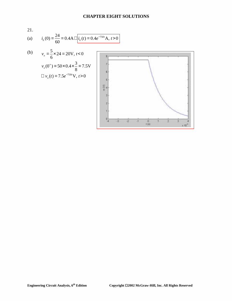
21.
(a) 75024(0) 0.4A ( ) 0.4 A, 060
−= = ∴ = >tL Li i t e t
(b)
750
5 24 20V, 06
3(0 ) 50 0.4 7.5V8
( ) 7.5 V, 0
+
−
= × = <
= × × =
∴ = >
x
x
tx
v t
v
v t e t

CHAPTER EIGHT SOLUTIONS
Engineering Circuit Analysis, 6th Edition Copyright 2002 McGraw-Hill, Inc. All Rights Reserved
22.
25 / 0.5 50
3 20 10 254
25 10 10 A, 0− −
= × + =
∴ = Ω∴ = = >
Lin L L
t tinin L
L
iv i i
vv i e e ti

CHAPTER EIGHT SOLUTIONS
Engineering Circuit Analysis, 6th Edition Copyright 2002 McGraw-Hill, Inc. All Rights Reserved
23.
= 2.5 A
24 /8 3
31 1
1 1
64 40(0) 5A4 40 8 48
5 5 A( ) 2.5 A, 0; ( 0.1)
(0.03) 2.285 A, (0.1) 1.8
− −
−
−
= × =+
∴ = =
∴ = > −
= =
L
t tL
t
i
i e ei t e t i
i i 52 A
CHAPTER EIGHT SOLUTIONS
Engineering Circuit Analysis, 6th Edition Copyright 2002 McGraw-Hill, Inc. All Rights Reserved
24. (a) (b)
100
1.5
(0) 4A 4 A, 0 15ms(15ms) 4 0.8925 A
−
− +
= ∴ = < <
∴ = =
tL L
L
i i e ti e
20( 0.015)
0.3
15ms: 0.8925 A(30ms) 0.8925 0.6612A
tL
L
t i ei e
+ − −
+ −
> =
∴ = =
CHAPTER EIGHT SOLUTIONS
Engineering Circuit Analysis, 6th Edition Copyright 2002 McGraw-Hill, Inc. All Rights Reserved
25. (a) 1 1 2 2(0 ) (0 ) 10A, (0 ) (0 ) 20A (0 ) 30Ai i i i i+ − + − += = = = ∴ =
(b) 0.08 5L / R ms 1.6667ms;48 3eq eqτ = = = =
(c) 1 2(0 ) 10A, (0 ) 20Ai i− −= = ; 600( ) 30 Ati t e−=
(d) 60048 1440 Vtv i e−= − = − (e) (f)
600 600 6001 00
6002 0
600 6000
10( 440) 10 24 10 24 14A
2.5( 1440) 20
6 20 6 14A
− − −
−
− −
= − + = + = −
= − +
= + = +
∫∫
t t t t t
t t
t t t
i e dt e e
i e dt
e e
2 2
2 2L
2 1200R 0 0
1 1W (0) 0.1 10 0.4 20 5 80 85J2 21 1W ( ) 0.1 14 0.4 14 9.8 39.2 49J2 2
900 48W 48 900 48 ( 1) 36J1200
49 36 85 checks
L
ti dt e dt∞ ∞ −
= × × + × × = + =
∞ = × × + × × = + =
×= = × = − =−
∴ + =
∫ ∫

CHAPTER EIGHT SOLUTIONS
Engineering Circuit Analysis, 6th Edition Copyright 2002 McGraw-Hill, Inc. All Rights Reserved
26. (a) (b) (c) τ = 400 s, so 1.2τ = 480 s. vC(1.2τ) = 33.33 e–1.2 = 10.04 V. Using Ohm’s law, we find that i1(1.2τ) = vC(1.2τ)/ 4000 = 2.51 mA. (d) PSpice Verification: We see from the DC analysis of the circuit that our initial value is correct; the Probe output confirms our hand calculations, especially for part (c).
1
c 1
2 2 100 2(0) 100 33.33V; (0 ) 16.667mA2 2 3 2 2 3
v (9 :59) 33.33V, (9 : 59) 16.667mA
cv i
i
−= × × = = × =+ +
∴ = =
/ 400 300/ 400
1
( ) 33.33 , 10 : 00 (10 : 05) 33.3315.74515.745 V, (10 : 05) 3.936mA4000
tc cv t e t v e
i
− −
+
= > ∴ =
= = =

CHAPTER EIGHT SOLUTIONS
Engineering Circuit Analysis, 6th Edition Copyright 2002 McGraw-Hill, Inc. All Rights Reserved
27.
250: 1.25 34 100(1.25 0.8 ) 25 0.2A20
xx x x x x x
it i i i i i i> = ∴ = − + + ∴ =
(a) (0 ) (1.25 0.8 1)0.2 0.290 Asi
− = − + = (b) (0 ) 0.2Axi
− =
(c) 5( ) 25 0.2 5 V (0 ) 0.05A100
t tc xv t e e i− − += × = ∴ = =
(d) 34 20 33.20.8 (0 ) 0.04A (0 ) 0.04 0.2767A120 120 120x si i+ += ∴ = − × = =
(e) 0.41(0.4) 5 0.03352A100xi e−= × =
CHAPTER EIGHT SOLUTIONS
Engineering Circuit Analysis, 6th Edition Copyright 2002 McGraw-Hill, Inc. All Rights Reserved
28. (a)
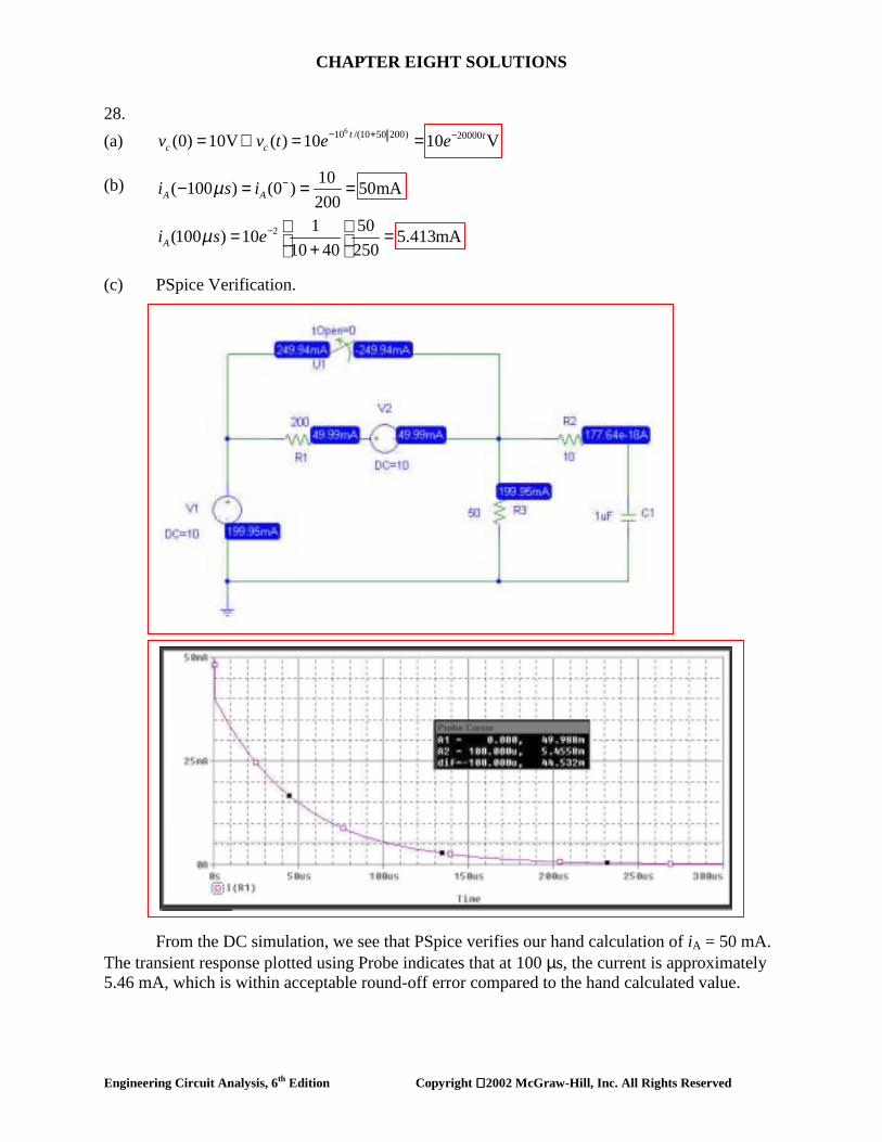
610 /(10 50 200) 20000(0) 10V ( ) 10 10 Vt tc cv v t e e− + −= ∴ = =
(b) (c) PSpice Verification. From the DC simulation, we see that PSpice verifies our hand calculation of iA = 50 mA. The transient response plotted using Probe indicates that at 100 µs, the current is approximately 5.46 mA, which is within acceptable round-off error compared to the hand calculated value.
2
10( 100 ) (0 ) 50mA2001 50(100 ) 10 5.413mA
10 40 250
A A
A
i s i
i s e
µ
µ
−
−
− = = =
= = +

CHAPTER EIGHT SOLUTIONS
Engineering Circuit Analysis, 6th Edition Copyright 2002 McGraw-Hill, Inc. All Rights Reserved
29.
(a) 112( ) 8( 1) 6mA ( 0)
12 4i t t= − = − <
+
(b)
6 310 /5 2 10 100
100
4 12 6 2 , (0) 48V
( ) 48 48 V, 0( ) 12 mA, 0
− × × −
−
= Ω =
∴ = = >
∴ = >
c
t tc
t
k v
v t e e ti t e t

CHAPTER EIGHT SOLUTIONS
Engineering Circuit Analysis, 6th Edition Copyright 2002 McGraw-Hill, Inc. All Rights Reserved
30. (a) (b)
6 610 /8 10 / 0.8
1,250,000 125,000
(0) 20V, (0) 80V
20 , 80
80 20 V, 0
− −
− −
= =
∴ = =
∴ = − = − >
CLeft CRIGHT
t tCL CR
t tout CR CL
v v
v e v ev v v e e t
1.25 0.125
6.25 0.625
(0 ) 60V; (1 ) 80 20 5.270V
(5 ) 80 20 10.551V
+ − −
− −
= = − =
= − = −out out
out
v v s e ev s e e
µµ

CHAPTER EIGHT SOLUTIONS
Engineering Circuit Analysis, 6th Edition Copyright 2002 McGraw-Hill, Inc. All Rights Reserved
31. (a) (b) vC(3 µs) = 9.447 V (c) PSpice verification. Note that the switch parameters had to be changed in order to
perform this simulation. As can be seen from the simulation results, our hand calculations are accurate.
610 / 4 250,000
0.25 400: 0 20V ( 0)5 10 4
1 0.250: Apply 1V 0.1 0.25A5
1R 40.25
( ) 20 20 V ( 0)− −
− −< + + = ∴ = <
−> = ∴ + − =
∴ = = Ω
∴ = = >
c c c cc
c in
eq
t tc
v v v vt v t
t v i
v t e e t

CHAPTER EIGHT SOLUTIONS
Engineering Circuit Analysis, 6th Edition Copyright 2002 McGraw-Hill, Inc. All Rights Reserved
32.
6
6 3
10 /( 1000) 500 /( 1000)
1000/ 2742.4
10 ( 10 )1
10
0 : (0) 60V500 1ms: 6060R500 1.2 0.18232 2 5.4848, 1742.4
R 1000 500(1ms) 60 41.67V
1ms : 41.67 /(1742.4 R 1000)
25 41.67
o o
c
t R Rc
oo
o
c
tc
t v
t v e e
n R
v e
t v e
e
−
− + − +
−
− −
−
< =
< < = ∴
∴ = = ∴ + = = Ω+
∴ = =
> = +
∴ =
l
00()1
1
31 1
1
.10000.5108 ,1742.4 R 10001742.4 R 1000
1 11957.6, R 1000 215.2 10 R 274.2R 215.2
−
∴ = ++
= = + = ∴ = Ω

CHAPTER EIGHT SOLUTIONS
Engineering Circuit Analysis, 6th Edition Copyright 2002 McGraw-Hill, Inc. All Rights Reserved
33. (a) With the switch closed, define a nodal voltage V1 at the top of the 5-kΩ resistor. Then, 0 = (V1 – 100)/ 2 + (V1 – VC)/ 3 + V1/ 5 [1] 0 = VC/ 10 + (VC – V1)/ 3 + (VC – 100) [2] Solving, we find that VC = vC(0-) = 99.76 V. (b)
710 /3939 25390 : R 10 6.5 3.939 87.59 87.59 V ( 0)− −> = = Ω∴ = = >t teq ct k v e e t

CHAPTER EIGHT SOLUTIONS
Engineering Circuit Analysis, 6th Edition Copyright 2002 McGraw-Hill, Inc. All Rights Reserved
34. t < 0:
3 9 6
1 1 1 1 1 1
1 1 1 1
/ 75 10 2 10 10 /150 6667
66671 4
12 4 20 0.5mA (0) 6 20 26(0) 13V
0: Apply 1mA 1 0.6 2.5mA; 30 75V R 75
( ) 13 13 13
( ) 0.4333 mA ( 0)3 10
−− × × × − −
−
= + ∴ = ∴ = + ==
> ← ∴ + = ∴ = ± = = ∴ = Ω
∴ = = =
∴ = = >×
c
c
in eq
t t tc
to
i i i v i i iv
t i i i v i k
v t e e evi t e t

CHAPTER EIGHT SOLUTIONS
Engineering Circuit Analysis, 6th Edition Copyright 2002 McGraw-Hill, Inc. All Rights Reserved
35. (a) 1 2(0 ) 100V. (0 ) 0, (0 ) 0Rv v v− − −= = = (b) 1 2(0 ) 100V. (0 ) 0, (0 ) 100VRv v v− + += = =
(c) 6 4 220 5 10 2 10 8 1020 5
sτ − −×= × × = ×+
(d) 12.5( ) 100 V, 0t
Rv t e t−= >
(e) 12.54
( )( ) 5 mA2 10
tRv ti t e−= =×
(f) (g)
6 33 12.5 12.5 12.5
1
12.5 12.5 12.52
10 10( ) 5 10 100 100 20 80V20 501000( ) 5 0 80 0 80 80V
5
− − − −
− − −
= − × + = + = − +
= + = − + = − +
∫
∫
t t t t too
t t t t too
v t e dt e e
v t e dt e e
6 2 6 21 2
6 21 2
6 25 4 4 6
1 1( ) 20 10 80 64mJ, ( ) 5 10 80 16mJ2 21(0) 20 10 100 100mJ, (0) 02
2525 10 2 10 2 10 ( 1)10 20mJ25
64 16 20 100 checks
− −
−
∞ − − −
∞ = × × × = ∞ × × × =
= × × × = =
= × × × = × × − =−
+ + =
∫
c c
c c
tR o
w w
w w
w e dt

CHAPTER EIGHT SOLUTIONS
Engineering Circuit Analysis, 6th Edition Copyright 2002 McGraw-Hill, Inc. All Rights Reserved
36. (a) 0: 1mA (0) 10V, (0) 1mA (0) 10V, 0s c L xt i v i v t< = ∴± = ↓ = − ∴ = < (b)
4 9/10 20 10 5000
3 3 / 0.1 3 10000 10000L
5000 10000
0 : ( ) 10 10 V
i ( ) 10 10 10 A ( ) V, 0( ) 10 V, 0
t tc
t t tL
t tx c L
t v t e et e e v t e t
v v v t e e t
−− × × −
− − − −
− −
> = =
= − − = − ∴ ± = >
∴ = − = − >

CHAPTER EIGHT SOLUTIONS
Engineering Circuit Analysis, 6th Edition Copyright 2002 McGraw-Hill, Inc. All Rights Reserved
37. (a) 0: 20V 20V, 20mA ( ) 20mA, 0< = ∴ = = ∴ = <s c L xt v v i i t t (b)
8 410000 / 2 10 10 5000
8 5000 5000
10000 5000 10000 5000
0: 0 ( ) 0.02 A; ( ) 20 20 V
( ) 2 10 20( 5000) 2 mA( ) ( ) ( ) 0.02 0.002 A 20 2 mA
t t ts L c
t tc
t t t tx L c
t v i t e v t e ei t e e
i t i t i t e e e e
−− − × −
− − −
− − − −
> = ∴ = = =
↓ = × × − = −
= + = − = −

CHAPTER EIGHT SOLUTIONS
Engineering Circuit Analysis, 6th Edition Copyright 2002 McGraw-Hill, Inc. All Rights Reserved
38. PSpice verification: Note that the switch properties were changed. We see from the simulation result that the current through the fuse (R3) is 869 mA, in agreement with our hand calculation.
( )
blow.not does fuse thems, 100 prior toA 1 than less todropped hascurrent thesince
A .868501.11.0
A )( :0
A 1.1909.01
RV)0(
1.0363.2
363.2
=∴
==
=>
===
×−
−
−
t
esietit
i
L
tL
L

CHAPTER EIGHT SOLUTIONS
Engineering Circuit Analysis, 6th Edition Copyright 2002 McGraw-Hill, Inc. All Rights Reserved
39. (a)
1
1
1 1
300 ( 1) V, 120 ( 1) V; 3 ( )A1001.5 : ( 1.5) 3 1A300
1200.5 : ( 0.5) 1 0.6A;300
120 300 1200.5 : 0.4A; 1.5 : 0.6A300 300 300
= − = − + = −
= − − = × =
−= − = + =
= = − = − = = − =
A B cv u t v u t i u t
t i
t i
t i t i
CHAPTER EIGHT SOLUTIONS
Engineering Circuit Analysis, 6th Edition Copyright 2002 McGraw-Hill, Inc. All Rights Reserved
40.
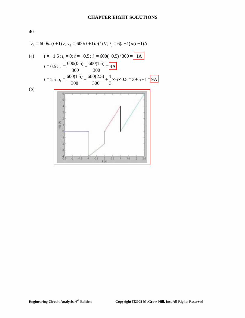
600 ( 1) , 600( 1) ( ) V, 6( 1) ( 1)AA B cv tu t v v t u t i t u t↑ = + = + = − − (a) (b)
1 1
1
1
1.5 : 0; 0.5 : 600( 0.5) / 300 1A600(0.5) 600(1.5)0.5 : 4A
300 300600(1.5) 600(2.5) 11.5 : 6 0.5 3 5 1 9A
300 300 3
= − = = − = − = −
= = + =
= = + + × × = + + =
t i t i
t i
t i

CHAPTER EIGHT SOLUTIONS
Engineering Circuit Analysis, 6th Edition Copyright 2002 McGraw-Hill, Inc. All Rights Reserved
41. (a) 2 ( 1) 3 (1) 4 (3) 3 4 1u u u− − + = − + = (b) (c) (1) 14 (1) 4 1.4715ue u e− − += =
[5 (2)] [2 (1)] [1 ( 1)]4 3 1 12
u u u− + − −= × × =

CHAPTER EIGHT SOLUTIONS
Engineering Circuit Analysis, 6th Edition Copyright 2002 McGraw-Hill, Inc. All Rights Reserved
42. (a) (b) t < 0: The voltage source is shorting out the 30-Ω resistor, so ix = 0. t > 0: ix = 60/ 30 = 2 A.
100 200: 0 10 6A50 50
600: 0 0 2A30
x
x
t i
t i
< = + + × =
> = + + =

CHAPTER EIGHT SOLUTIONS
Engineering Circuit Analysis, 6th Edition Copyright 2002 McGraw-Hill, Inc. All Rights Reserved
43. 0.5 :t = − 200 1/ 50 150 25 16.667, 2 3 2.5A66.67 1/ 50 1/ 25 1/ 50 2xi= = − = − =
+ +
0.5 :t = 200 3A66.67xi = =
1.5 :t = 100 13 2.5A66.67 3xi = − × =
2.5 :t = 200 100 2A50xi−= =
3.5 :t = 100 2A50xi = − = −

CHAPTER EIGHT SOLUTIONS
Engineering Circuit Analysis, 6th Edition Copyright 2002 McGraw-Hill, Inc. All Rights Reserved
44. ( ) 4 16 ( ) 20 ( 4) 6 ( 6)Vv t u t u t u t= − + − − −
t (s)
v(t) (V)
4
-12
8
2
0 4 6

CHAPTER EIGHT SOLUTIONS
Engineering Circuit Analysis, 6th Edition Copyright 2002 McGraw-Hill, Inc. All Rights Reserved
45. (a) (b) Resistor of value 2Ω
7 ( ) 0.2 ( ) 8( 2) 3(1) 9.8 volts
− + − +=
u t u t tv

CHAPTER EIGHT SOLUTIONS
Engineering Circuit Analysis, 6th Edition Copyright 2002 McGraw-Hill, Inc. All Rights Reserved
46. (a) 200000( ) (2 2 ) ( )mt
Li t e u t−= − mA (b)
3 3
200000 200000
( ) L 15 10 10 ( 2)
( 200000 ) ( ) 6 ( )V
− −
− −
′= = × × −
− =L L
t t
v t ie u t e u t

CHAPTER EIGHT SOLUTIONS
Engineering Circuit Analysis, 6th Edition Copyright 2002 McGraw-Hill, Inc. All Rights Reserved
47. (a) 2.5
1( ) 2 2(1 ) ( ) A ( 0.5) 2AtLi t e u t i−= + − ∴ − =
(b) 1.25(0.5) 2 2(1 ) 3.427ALi e−= + − = (c) 3.75(1.5) 2 2(1 ) 3.953ALi e−= + − =

CHAPTER EIGHT SOLUTIONS
Engineering Circuit Analysis, 6th Edition Copyright 2002 McGraw-Hill, Inc. All Rights Reserved
48.
AiAii
ii
nsRL
R
L
L
L
th
3
31
331
3
6
333
33
102.3
10101010.107.4.
156102.310500
102.3107.41010107.41010
−
−
−
×=∴
×=+
×=×
=××==
Ω×=×+××××=
τ
(a)
(b)
(c)

CHAPTER EIGHT SOLUTIONS
Engineering Circuit Analysis, 6th Edition Copyright 2002 McGraw-Hill, Inc. All Rights Reserved
49. (a) (b) 1000
1( ) (100 80 ) ( )Vtv t e u t−= −
20 / 0.02
1000
( ) (4 4 ) ( )( ) 4(1 ) ( )A
tL
tL
i t e u ti t e u t
−
−
= −
∴ = −

CHAPTER EIGHT SOLUTIONS
Engineering Circuit Analysis, 6th Edition Copyright 2002 McGraw-Hill, Inc. All Rights Reserved
50. (a) 0 W (b) The total inductance is 30 || 10 = 7.5 mH. The Thévenin equivalent resistance is
12 || 11 = 5.739 kΩ. Thus, the circuit time constant is L/R = 1.307 µs. The final value of the total current flowing into the parallel inductor combination is 50/12 mA = 4.167 mA. This will be divided between the two inductors, so that i(∞) = (4.167)(30)/ (30 + 10) = 3.125 mA.
We may therefore write i(t) = 3.125[1 – e-106t/ 1.307] A. Solving at t = 3 µs, we find 2.810 A. (c) PSpice verification
We see from the Probe output that our hand calculations are correct by verifying using the cursor tool at t = 3 µs.

CHAPTER EIGHT SOLUTIONS
Engineering Circuit Analysis, 6th Edition Copyright 2002 McGraw-Hill, Inc. All Rights Reserved
51. (a) ( ) 10 , 0= <Li t A t (b)
5 / 0.5
10
( ) 8 2( ) 8 2 A, 0
tL
tL
i t ei t e t
−
−
= +
∴ = + >

CHAPTER EIGHT SOLUTIONS
Engineering Circuit Analysis, 6th Edition Copyright 2002 McGraw-Hill, Inc. All Rights Reserved
52. (a) ( ) 2A, 0Li t t= > (b)
4 /0.1
40
( ) 5( ) 5 3 A, 0
tL
tL
i t ei t e t
−
−
= −
∴ = − >
CHAPTER EIGHT SOLUTIONS
Engineering Circuit Analysis, 6th Edition Copyright 2002 McGraw-Hill, Inc. All Rights Reserved
53. (a) (b)
(c) 2510 10 ( )Q( ) 2 2 ( ) 0.16 0.08 A, 05
−+= = + ∴ = − >tu tt u t i e t
(d)
P Q, Q , R 125 , L 5H
L LP LQ LP 5P R 125 P 25
− −+ = = + = Ω =
∴ = ∴ = = = ∴ =
∫Pt Pt Ptdi i i e e dt Aedt
di idt
25 25 25 25 25 25
25
10 2Q( ) 2 2 A AL 25
2 10 2 2A , (0) A 0 0.08A25 125 25 25
− − − −
−
= = ∴ = + = × +
∴ = + = = ∴ = ∴ = =
∫tt t t t t t t
oo
t
t i e e dt e e e e
i e i i
25 25 25 25
25
10 ( ) 2Q( ) 2 ( ) 2 A A5 25
2(0) 0 A ( ) 0.08(1 )A, 025
− − −
−
= = ∴ = + = +
= ∴ = − ∴ = − >
∫tt t t t
o
t
u tt u t i e e dt e e
i i t e t
25 25 25
2525 25
2 2
2525 25
10 ( )cos50Q( ) 2 ( )cos50 2cos505
2 (25cos50 50sin 50 ) A50 25
12 (25cos50 50sin 50 ) 25 A3125 3125
2 4 2cos50 sin 50125 125 125
− −
− −
− −
= = ∴ = × +
∴ = + + +
= + − × +
= + −
∫tt t t
o
ttt t
o
tt t
u t tt u t t i e t e dt Ae
ei e t t e
ee t t e
t t e 25 25
25
A
2 2(0) 0 0 A A 0125 125
( ) 0.016cos50 0.032sin 50 0.016 A, 0
− −
−
+
= ∴ = − + ∴ =
∴ = + − >
t t
t
e
i
i t t t e t

CHAPTER EIGHT SOLUTIONS
Engineering Circuit Analysis, 6th Edition Copyright 2002 McGraw-Hill, Inc. All Rights Reserved
54. (a) 0, 0 (b) 0, 200V (c) 1A, 100V (d)
34000
40001 1
50 10 1 ms 1(1 ) ( )A, (0.2ms) 0.5507A200 4
( ) (100 100 ) ( )V, (0.2ms) 144.93V
tL L
t
i e u t i
v t e u t v
τ−
−
−
×= = ∴ = − =
= + =

CHAPTER EIGHT SOLUTIONS
Engineering Circuit Analysis, 6th Edition Copyright 2002 McGraw-Hill, Inc. All Rights Reserved
55.
(a) 100 100( ) 15A, 020 5Li t t= − = − <
(b) (0 ) (0 ) 15AL Li i+ −= = −
(c) 100( ) 5A20Li ∞ = =
(d) 40( ) 5 20 A, 0t
Li t e t−= − >

CHAPTER EIGHT SOLUTIONS
Engineering Circuit Analysis, 6th Edition Copyright 2002 McGraw-Hill, Inc. All Rights Reserved
56.
L9000
9000
9000
18 1(0 ) 0.1A (0 ) 0.1A60 30 2
i ( ) 0.1 0.1 0.2A( ) 0.2 0.1 A, 0( ) 0.1 ( ) (0.2 0.1 ) ( )A
or, ( ) 0.1 (0.1 0.1 ) ( )A
− +
−
−
−
= × = ∴ =+
∞ = + =
∴ = − >
∴ = − + −
= + −
L L
tL
tL
tL
i i
i t e ti t u t e u ti t e u t

CHAPTER EIGHT SOLUTIONS
Engineering Circuit Analysis, 6th Edition Copyright 2002 McGraw-Hill, Inc. All Rights Reserved
57.
(a) 30 3(0 ) 3A, (0 ) 4A7.5 4x Li i− −= × = =
(b) (0 ) (0 ) 4Ax Li i+ += = (c) 10 / 0.5 20
0.8
( ) ( ) 3A
( ) 3 1 3 A (0.04)3 3.449A
− −
−
∞ = ∞ =
∴ = + = + ∴
= + =
x Lt t
x x
i ii t e e i
e

CHAPTER EIGHT SOLUTIONS
Engineering Circuit Analysis, 6th Edition Copyright 2002 McGraw-Hill, Inc. All Rights Reserved
58.
(a) 30(0 ) (0 ) 3A10x Li i− −= = =
(b) (c)
30 30 15(0 ) 3 2.4A30 7.5 40 10 15
+ = × + × =+ +xi
6 / 0.5
12 0.48
30 30( ) 3A ( ) 3 0.67.5 40
3 0.6 (0.04) 3 0.6 2.629A
tx x
tx
i i t e
e i e
−
− −
∞ = × = ∴ = −
= − ∴ = − =

CHAPTER EIGHT SOLUTIONS
Engineering Circuit Analysis, 6th Edition Copyright 2002 McGraw-Hill, Inc. All Rights Reserved
59.
52 / 0.2 260
260
OC : 0, 4 ( )V0.2SC : 0.1 ( ) ,12 ( ) 0.6 2
40 6012 ( ) 12 ( ) ( )
2.6 60 2.6 60 134 ( ) ( )4 13 52 (1 ) ( ) (1 ) ( )
52 1360 4.615 (1 ) ( )V
− −
+ −
= =−= + = +
∴ = ∴ = = =×
∴ = × = Ω∴ = − = −
∴ = = −
x oc
x x xx x
xx ab
t tth L
tx L
v v u tv v vu t u t v v
vu t u t u tv i
u t u tR i e u t e u t
v i e u t

CHAPTER EIGHT SOLUTIONS
Engineering Circuit Analysis, 6th Edition Copyright 2002 McGraw-Hill, Inc. All Rights Reserved
60. (a) (b)
1 1 1
1
40
OC : 100 30 20 0, 2A80 ( )V
20 10SC : 10A, 10 20A20
R 4 ( ) 20(1 ) ( )A−
− + + = =∴ =
×= ↓ = + =
∴ = Ω∴ = −
oc
sc
tth L
i i iv u t
i i
i t e u t
40 40
4040
1
0.1 20 40 ( ) 80 ( )
100 ( ) 80 ( )( ) 10 8 ( )A10
t tL
tt
v e u t e u tu t e u ti t e u t
− −
−−
= × × =
−∴ = = −

CHAPTER EIGHT SOLUTIONS
Engineering Circuit Analysis, 6th Edition Copyright 2002 McGraw-Hill, Inc. All Rights Reserved
61. Unfortunately, PSpice will not allow us to use negative time values. Thus, we must perform the simulation starting from t = 0, and manually shift the results if needed to account for sources that change value prior to t = 0.
Voltage source vB(t) from Exercise 39.
Current source iC(t) from Exercise 39.

CHAPTER EIGHT SOLUTIONS
Engineering Circuit Analysis, 6th Edition Copyright 2002 McGraw-Hill, Inc. All Rights Reserved
62. (a) (b) PSpice verification. As can be seen from the plot above, the PSpice simulation results confirm our hand calculations of vC(t < 0) = 2 V and vC(t = 2 µs) = -3.06 V
9 310 / 2 10 500000
1
6(0 ) 3 2V (0 )9
6( ) 2 6(2 7) 6V7
( ) 6 8 6 8 V, 0
( 2 ) (0 ) 2V, (2 ) 6 8 3.057V
− +
− × −
− −
= × = =
∞ = − = −
∴ = − + = − + >
− = = = − + = −
c c
c
t tc
c c c
v v
v
v t e e tv s v v s eµ µ

CHAPTER EIGHT SOLUTIONS
Engineering Circuit Analysis, 6th Edition Copyright 2002 McGraw-Hill, Inc. All Rights Reserved
63.
8 3 510 /10 10
10(0 ) 2.5mA, ( ) 10mA4
10 7.5(0) 7.5V (0 ) 17.5mA1 1
10 7.5 10 7.5 mA, 0, 2.5mA 0
−
+
− −
= = ∞ =
= ∴ = + =
= + = + > = <
A A
c A
t tA A
i i
v i
i e e t i t

CHAPTER EIGHT SOLUTIONS
Engineering Circuit Analysis, 6th Edition Copyright 2002 McGraw-Hill, Inc. All Rights Reserved
64.
8 310 /1.75 10 57140
10(0 ) 10mA, ( ) 2.5mA, (0) 0110 1(0 ) 1.4286mA 10mA, 0
1.75 42.5 (1.4286 2.5) 2.5 1.0714 mA, 0
A A c
A A
t tA
i i v
i i t
i e e t
−
+
− × −
= = ∞ = =
= × ∴ = <
= + − = − >

CHAPTER EIGHT SOLUTIONS
Engineering Circuit Analysis, 6th Edition Copyright 2002 McGraw-Hill, Inc. All Rights Reserved
65. (a) (b)
3 7 3
500
500
12 ( ) 24 ( )V0: (0 ) 8V (0 ) 8V
20: ( ) 24 16V3
200RC 10 3 10 2 1030
( ) 16 24 V, 0( ) 8 ( ) (16 24 ) ( )
s
c c
c
tc
tc
v u t u tt v v
t v
v t e tv t u t e u t
− +
− −
−
−
= − − +
< = − ∴ = −
> ∞ = × =
= × × × = ×
∴ = − >
∴ = − − + −
500
12 24 8(0 ) 0.4mA, (0 ) 3.2mA30 10
24( ) 0.8mA30
( ) 0.4 ( ) (0.8 2.4 ) ( )mA
in in
in
tin
i i
i
i t u t e u t
− +
−
− += = − = =
∞ = =
= − + +

CHAPTER EIGHT SOLUTIONS
Engineering Circuit Analysis, 6th Edition Copyright 2002 McGraw-Hill, Inc. All Rights Reserved
66. (a) iin (-1.5) = 0 (b) iin (1.5) = 0
(0 ) 10V (0 ), (0 ) 0
(0 ) 0 ( ) 0 for all
− + −
+
= = =
= ∴ =c c in
in in
v v ii i t t

CHAPTER EIGHT SOLUTIONS
Engineering Circuit Analysis, 6th Edition Copyright 2002 McGraw-Hill, Inc. All Rights Reserved
67.
2.5
0.375 20( 0.5) 7.5( 0.5)
7.5(0.3)
0 0.5 : 10(1 )V(0.4) 6.321V, (0.5) 7.135V
20 10 5 5 50 80.5: A ( ) 10 8 V, 4 812 6 6 3 3
50 50( ) 7.135 16.667 9.532 V3 3
(0.8) 16.667 9.532 15.
tc
c c
c
t tc
c
t s v ev v
t v
v t e e
v e
−
− × − − −
−
< < = −= =
−> = ∴ ∞ = + + = = Ω
= + − = − ∴ = − = 662V
CHAPTER EIGHT SOLUTIONS
Engineering Circuit Analysis, 6th Edition Copyright 2002 McGraw-Hill, Inc. All Rights Reserved
68.
6/ 10 /33.33
30,000
3OC : 0 1, 3 1 2V100 100 100
SC : 3V 0.06A100 100
R / 2 / 0.06 33.33
(1 ) 2(1 )
2(1 ) V, 0
th
x x xx oc
x xx sc
th oc sc
t R C tc oc
t
v v v v v
v vv i
v i
v v e ee t
− −
−
− −− + = ∴ = = − =
= ∴ = + =
∴ = = = Ω
∴ = − = −
= − >

CHAPTER EIGHT SOLUTIONS
Engineering Circuit Analysis, 6th Edition Copyright 2002 McGraw-Hill, Inc. All Rights Reserved
69. (a) 0 : 8(10 20) 240V ( ) 80V, 0Rt v t t< + = = = < (b)
(c) 0 : ( ) 80VRt v t< = (d)
6/10 10 100000
100000
0 : ( ) 8 30 240V (0 ) 240V1( ) : ( ) 8(10 10) 80V2
( ) 80 160 80 160 V
( ) 80 160 V, 0
c c
c
t tc
tR
t v t v
t v
v t e ev t e t
−
+
− × −
−
< = × = ∴ =
= ∞ ∞ = × + =
∴ = + = +
∴ = + >
6/50 10 20000
20000
(0 ) 80V, ( ) 240V ( ) 240 160 240 160 V20 80(0 ) 80V, (0 ) 8 10 10 32 16 48V
30 20 50( ) 80V ( ) 80 32 V, 0
t tc c c
R R
tR R
v v v t e e
v v
v v t e t
−− − × −
− +
−
= ∞ = ∴ = − = −
= = × + × = + =+
∞ = ∴ = − >

CHAPTER EIGHT SOLUTIONS
Engineering Circuit Analysis, 6th Edition Copyright 2002 McGraw-Hill, Inc. All Rights Reserved
70. (a) For t < 0, there are no active sources, and so vC = 0. For 0 < t < 1, only the 40-V source is active. Rth = 5k || 20 k = 4 kΩ and hence τ = Rth C = 0.4 s. The “final” value (assuming no other source is ever added) is found by voltage division to be vC(∞) = 40(20)/(20 + 5) = 32 V. Thus, we may write vC(t) = 32 + [0 – 32] e–t/ 0.4 V = 32(1 – e-2.5t) V.
For t > 1, we now have two sources operating, although the circuit time constant remains unchanged. We define a new time axis temporarily: t' = t – 1. Then vC(t' = 0+) = vC(t = 1) = 29.37 V. This is the voltage across the capacitor when the second source kicks on. The new final voltage is found to be vC(∞) = 40(20)/ (20 + 5) + 100(5)/ (20 + 5) = 52 V.
Thus, vC(t') = 52 + [29.37 – 52] e-2.5t' = 52 – 22.63 e-2.5(t – 1) V.
(b) (c)
For t < 0, vC = 0.
We see from the simulation results that our hand calculations and sketch are indeed correct.

CHAPTER EIGHT SOLUTIONS
Engineering Circuit Analysis, 6th Edition Copyright 2002 McGraw-Hill, Inc. All Rights Reserved
71.
2000,
1000,
, ,
2000 1000
1000 1000 2
1000
1000
200 V
100(1 )V0
200 100 100100 200( ) 100 0,
100 10,000 80,000 0.25 0.75400
0.5, 0.6931ms
−
−
− −
− −
−
−
=
= −= − =
∴ = −∴ + − =
− ± += = − ±
∴ = =
tx L
tx c
x x L x c
t t
t t
t
t
v e
v ev v v
e ee e
e
e t

CHAPTER EIGHT SOLUTIONS
Engineering Circuit Analysis, 6th Edition Copyright 2002 McGraw-Hill, Inc. All Rights Reserved
72.
61
1 1
62
10 /( 100)
1000/( 100) 1000 /( 100)
11
10 /( 100) 3 10002
22
0 : 0
0 1ms : 9(1 )18 9(1 ),9
1000 2.197, R 355.1R 100
1ms : 8 , 10 1 8 (R 100)1000 2.079, R 480.9 100 380.9
R 100
c
t Rc
R R
t Rc
t v
t v e
e e
t v e t t e
− +
− + − +
′− + − −
< =
< < = −
∴ = − =
∴ = = Ω+
′> = = − ∴ − +
∴ = = − = Ω+

CHAPTER EIGHT SOLUTIONS
Engineering Circuit Analysis, 6th Edition Copyright 2002 McGraw-Hill, Inc. All Rights Reserved
73. For t < 0, the voltage across all three capacitors is simply 9 (4.7)/ 5.7 = 7.421 V. The circuit time constant is τ = RC = 4700 (0.5455×10⁻⁶) = 2.564 ms. When the circuit was first constructed, we assume no energy was stored in any of the
capacitors, and hence the voltage across each was zero. When the switch was closed, the capacitors began to charge according to ½ Cv2. The capacitors charge with the same current flowing through each, so that by KCL we may write
dtdvC
dtdvC
dtdvC 3
32
21
1 ==
With no initial energy stored, integration yields the relationship C1v1 = C2v2 = C3v3 throughout the charging (i.e. until the switch is eventually opened). Thus, just prior to the switch being thrown at what we now call t = 0, the total voltage across the capacitor string is 7.421 V, and the individual voltages may be found by solving:
v1 + v2 + v3 = 7.421 10-6 v1 – 2×10⁻⁶ v2 = 0 2×10⁻⁶ v2 – 3×10⁻⁶ v3 = 0 so that v2 = 2.024 V. With the initial voltage across the 2-uF capacitor now known, we may write
v(t) = 2.024 e-t/ 2.564×10⁻³ V
(a) v(t = 5.45 ms) = 241.6 mV. (b) The voltage across the entire capacitor string can be written as 7.421 e-t/ 2.564×10⁻³
V. Thus, the voltage across the 4.7-kΩ resistor at t = 1.7 ms = 3.824 V and the dissipated power is therefore 3.111 mW.
(c) Energy stored at t = 0 is ½ Cv2 = 0.5(0.5455×10⁻⁶)(7.421)2 = 15.02 µJ.
CHAPTER EIGHT SOLUTIONS
Engineering Circuit Analysis, 6th Edition Copyright 2002 McGraw-Hill, Inc. All Rights Reserved
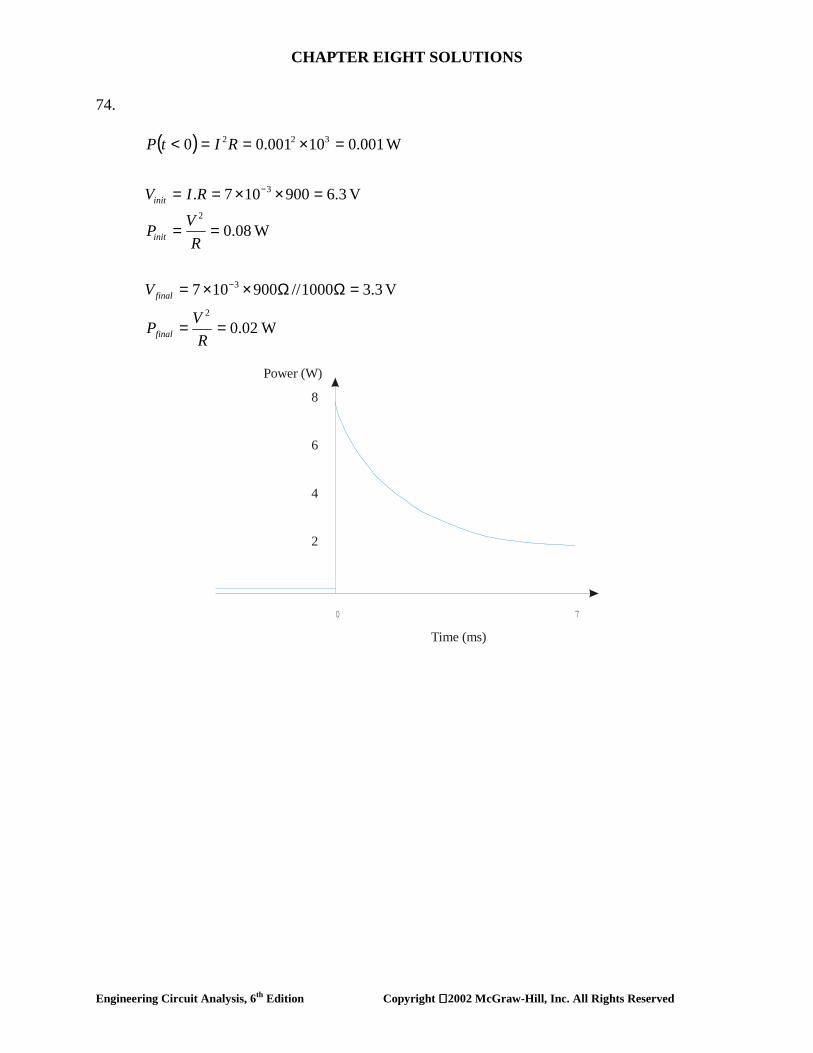
74.
( )
W0.02
V 3.31000//900107
W0.08
V 6.3900107.
W0.00110001.00
2
3
2
3
322
==
=ΩΩ××=
==
=××==
=×==<
−
−
RVP
V
RVP
RIV
RItP
final
final
init
init
8
6
4
2
Power (W)
0 7
Time (ms)

CHAPTER EIGHT SOLUTIONS
Engineering Circuit Analysis, 6th Edition Copyright 2002 McGraw-Hill, Inc. All Rights Reserved
75. voltage follower 2( ) ( )ov t v t∴ = PSpice verification:
From the simulation results, we see that modeling the operation of this circuit using an ideal op amp model does not provide an accurate accounting for the operation of the actual circuit.
2
20.1
(0 ) 5(0.25 1) 1 ( )Vv ( ) 0, 1.25 8 10
( ) ( )V
+
−
= =∞ = = × =
∴ = to
v u ts
v t e u tτ

CHAPTER EIGHT SOLUTIONS
Engineering Circuit Analysis, 6th Edition Copyright 2002 McGraw-Hill, Inc. All Rights Reserved
76. voltage follower 2( ) ( )ov t v t∴ =
6
2
10 / 0.5 200
10,000
( ) 1.25 ( )V ( )
( ) 1.25 ( )1.25 ( )V
− ×
−
= =
=
=
o
xt
v t u t v t
v t e u te u t

CHAPTER EIGHT SOLUTIONS
Engineering Circuit Analysis, 6th Edition Copyright 2002 McGraw-Hill, Inc. All Rights Reserved
77. (a) And we may write vo(t) = -0.2[1 + e-20×103t]u(t) V. (b) PSpice verification:
We can see from the simulation result that our ideal op amp approximation is not providing a great deal of accuracy in modeling the transient response of an op amp in this particular circuit; the output was predicted to be negative for t > 0.
20,0001 4
7 20,000 20,0004
20,000
3 20,000
20,000 20,000
40 (virtual gnd) ( )A10
410 0.210
( ) 0.2(1 ) ( )( ) 10 ( ) 0.4 ( )V( ) ( ) ( ) ( 0.2 0.2 0.4 ) ( )
t
t t t tc oo
tc
tR
t to c R
v i e u t
v e dt e
v t e u tv t i t e u tv t v t v t e e u t
−
− −
−
−
− −
= ∴ =
∴ = = −
∴ = −
∴ = =
∴ = − − = − + −
∫
CHAPTER EIGHT SOLUTIONS
Engineering Circuit Analysis, 6th Edition Copyright 2002 McGraw-Hill, Inc. All Rights Reserved
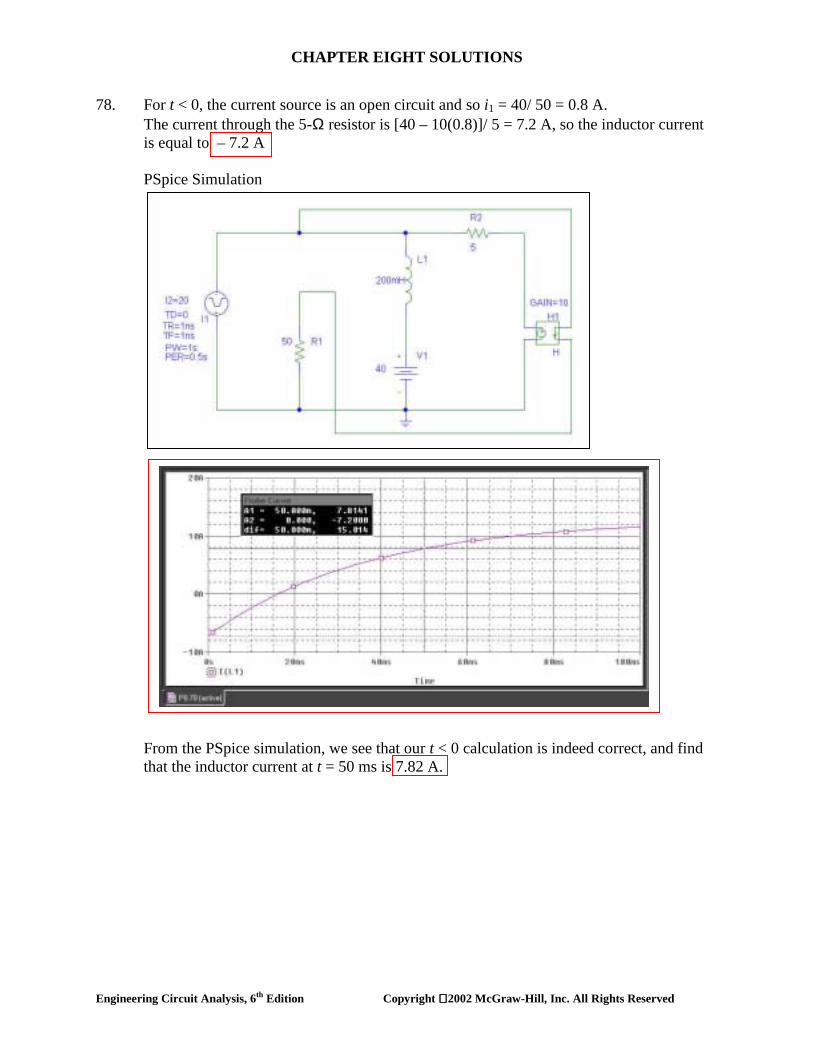
78. For t < 0, the current source is an open circuit and so i1 = 40/ 50 = 0.8 A. The current through the 5-Ω resistor is [40 – 10(0.8)]/ 5 = 7.2 A, so the inductor current is equal to – 7.2 A PSpice Simulation From the PSpice simulation, we see that our t < 0 calculation is indeed correct, and find that the inductor current at t = 50 ms is 7.82 A.

CHAPTER EIGHT SOLUTIONS
Engineering Circuit Analysis, 6th Edition Copyright 2002 McGraw-Hill, Inc. All Rights Reserved
79. Assume at least 1 µA required otherwise alarm triggers. Add capacitor C.
61
106
(1) 1 volt1000(0) .1.5 1.496 volts
1002.371We have 1 1.496 or C 2.48 F
10 (1.496)−
=
= =
∴ = = = µl
c
c
C
v
v
en

CHAPTER EIGHT SOLUTIONS
Engineering Circuit Analysis, 6th Edition Copyright 2002 McGraw-Hill, Inc. All Rights Reserved
80. One possible solution of many: implement a capacitor to retain charge; assuming the light is left on long enough to fully charge the capacitor, the stored charge will run the lightbulb after the wall switch is turned off. Taking a 40-W light bulb connected to 115 V, we estimate the resistance of the light bulb (which changes with its temperature) as 330.6 Ω. We define “on” for the light bulb somewhat arbitrarily as 50% intensity, taking intensity as proportional to the dissipated power. Thus, we need at least 20 W (246 mA or 81.33 V) to the light bulb for 5 seconds after the light switch is turned off.
The circuit above contains a 1-MΩ resistor in parallel with the capacitor to allow current to flow through the light bulb when the light switch is on. In order to determine the required capacitor size, we first recognise that it will see a Thevenin equivalent resistance of 1 MΩ || 330.6 Ω = 330.5 Ω. We want vC(t = 5s) = 81.33 = 115e-5/τ, so we need a circuit time constant of t = 14.43 s and a capacitor value of τ/ Rth = 43.67 mF.