
CHAPTER / CONTENT - جامعة نزوى · CHAPTER / CONTENT Definition & Application ... AIChE...
29
1 CHAPTER / CONTENT Definition & Application LLE for Partially Miscible Solvent LLE for Immiscible Solvent Liquid – liquid extraction equipment Solvent selectivity
Transcript of CHAPTER / CONTENT - جامعة نزوى · CHAPTER / CONTENT Definition & Application ... AIChE...
1
CHAPTER / CONTENT
Definition & Application
LLE for Partially Miscible Solvent
LLE for Immiscible Solvent
Liquid – liquid extraction equipment
Solvent selectivity
2
The separation of constituents (solutes) of a liquid solution by contact with another insoluble liquid.
Solutes are separated based on their different solubilities in different liquid.
The separation process of the components of a liquid mixture by treatment
with a solvent in which one or more desired components is soluble.
There are two requirements for liquid – liquid extraction to be feasible:
component (s) to be removed from the feed must preferentially distribute in the solvent.
the feed and solvent phases must be substantially immiscible
Definition & Application
The two liquid phases must be either immiscible, or partially miscible.
• usually isothermal and isobaric
• can be done at low temperature (good for thermally fragile solutes, such as large organic molecules or biomolecules)
• can be very difficult to achieve good contact between poorly miscible liquids (low stage efficiency)
• extracting solvent is usually recycled, often by distillation (expensive and energy-intensive)
• can be single stage (mixer-settler) or multistage (cascade)
3
The simplest LLE involves only a ternary (i.e 3 component system)
Important terms you need to know:
Feed - The solution which is to be extracted (denoted by component A)
Solvent - The liquid with which the feed is contacted (denoted by component C)
Diluent - ‘Carrier’ liquid (denoted by component B)
Extract (E) - The solvent – rich product of the operation
Raffinate (R) -The residual liquid from which solutes has been
removed.
Definition & Application
In some operations, the solutes are the desired product, hence the extract stream is the desirable stream. In other applications, the solutes my be contaminants that need to be removed, and in this instance the raffinate is the desirable product stream.
Extraction processes are well suited to the petroleum industry because of
the need to separate heat – sensitive liquid feeds according to chemical type (e.g aromatic, naphthenic) rather than by molecular weight or vapor pressure.
Application:
Major applications exist in the biochemical or pharmaceutical industry, where emphasis is on the separation of antibiotics and protein recovery.
In the inorganic chemical industry, they are used to recover high – boiling components such as phosphoric acid, boric acid and sodium hydroxide from aqueous solution.
Definition & Application
4
Examples:
Extraction of nitrobenzene after reaction of HNO3 with toluene in H2SO4
Extraction of methylacrylate from organic solution with
perchlorethylene Extraction of benzylalcohol from a salt solution with toluene. Removing of H2S from LPG with MDEA Extraction of caprolactam from ammonium sulfate solution with
benzene Extraction of acrylic acid from wastewater with butanol Removing residual alkalis from dichlorohydrazobenzene with water
Definition & Application
Examples:
Extraction of methanol from LPG with water
Extraction of chloroacetic acid from methylchloroacetate with water.
Definition & Application
The difference between LLE and distillation process in the separation of liquid mixtures:
LLE depends on solubilities between the liquid components and produces new solution which in turn has to be separated again, whereas;
Distillation depends on the differences in relative volatilities / vapor
pressures of substances. Furthermore, it requires heat addition.
5
Definition & Application
Advantages of LLE over distillation process:
Where distillation requires excessive amount of heat Presence of azeotropes or low relative volatilities are involved
(α value near unity and distillation cannot be used) Dissolved or complex inorganic substances in organic or
aqueous solution Removal of a component present in small concentrations, e.g
hormones in animal oil. Recovery of a high – boiling point component present in small
quantities in waste stream, e.g acetic acid from cellulose acetate. Recovery of heat – sensitive materials (e.g food) where low to
moderate processing temperatures are needed. Thermal decomposition might occur.
Solvent recovery is easy and energy savings can be realized.
Solvent selectivity
The solvent is the key to a successful separation by LLE. The several criteria: • Distribution Coefficient.
This is the ratio (at equilibrium) of the concentration of solute in the extract and raffinate phases. It gives a measure of the affinity of the solute for the two phases.
Selectivity (Separation factor).
If there are more than one solutes (sat two solutes A and B), then consideration should be given to the selectivity of the solvent for solutes A against B. The selectivity between two solutes A and B is defined as the ratio of the distribution coefficient of A to the distribution coefficient of B. For all useful extraction operation the selectivity must exceed unity. If the selectivity is unity, no separation is possible.
6
Solvent selectivity
Insolubility of Solvent.
The solvent should have low solubility in the feed solution, otherwise the separation is not “clean”. For example, if there is significant solubility of solvent in the raffinate stream, an additional separation step is required to recover the solvent.
Recoverability.
It is always necessary to recover the solvent for re-use, and this must ordinarily be done by other means, e.g distillation and the solvent should also be thermally – stable under the distillation temperature.
Density.
A large difference in density between extract and raffinate phases permits high capacities in equipment. This is especially important for extraction devices utilizing gravity for phase separation.
Solvent selectivity
Chemical Reactivity.
The solvent should be stable chemically and inert toward the other components of the system and toward the common materials of construction.
Availability and Cost.
Other Criteria.
Toxicity and flammability of the solvent are important occupational health and safety consideration.
Stability of the solvent (i.e resistance to breakdown), particularly in the recovery steps, is significant, especially if the breakdown products might contaminate the products of the main separation.
7
(a) A homogeneous solution may be formed and the selected solvent is then unsuitable.
(b) The solvent may be completely immiscible with the initial solvent.
(c) The solvent may be partially miscible with the original solvent resulting in the formation of one pair of partially miscible liquids.
(d) The new solvent may lead to the formation of two or three partially miscible liquids.
1
N
F, xA,0
S, yA,N+1
E, yA,1
R, xA,N
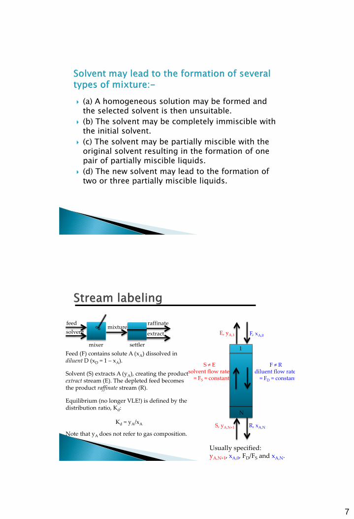
Usually specified: yA,N+1, xA,0, FD/FS and xA,N.
Feed (F) contains solute A (xA) dissolved in diluent D (xD = 1 – xA).
Solvent (S) extracts A (yA), creating the product extract stream (E). The depleted feed becomes the product raffinate stream (R).
Equilibrium (no longer VLE!) is defined by the distribution ratio, Kd:
Kd = yA/xA
Note that yA does not refer to gas composition.
F ≠ R diluent flow rate = FD = constant
S ≠ E solvent flow rate = FS = constant
feed mixture
extract
raffinate
mixer settler
solvent
8
SINGLE STAGE CALCULATIONS
MULTISTAGE COUNTER CURRENT SYSTEM
LLE for Partially Miscible Solvent/Immiscible
MULTIPLE STAGES WITH CROSSFLOW OF SOLVENT
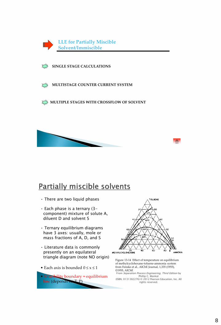
• There are two liquid phases
• Each phase is a ternary (3-component) mixture of solute A, diluent D and solvent S
• Ternary equilibrium diagrams have 3 axes: usually, mole or mass fractions of A, D, and S
• Literature data is commonly presently on an equilateral triangle diagram (note NO origin)
From Separation Process Engineering, Third Edition by Phillip C. Wankat
(ISBN: 0131382276) © 2012 Pearson Education, Inc. All rights reserved.
Figure 13-14 Effect of temperature on equilibrium of methylcyclohexane-toluene-ammonia system from Fenske et al., AIChE Journal, 1,335 (1955), ©1955, AIChE
• Each axis is bounded 0 ≤ x ≤ 1
• Miscibility boundary = equilibrium line (depends on T, P)
9
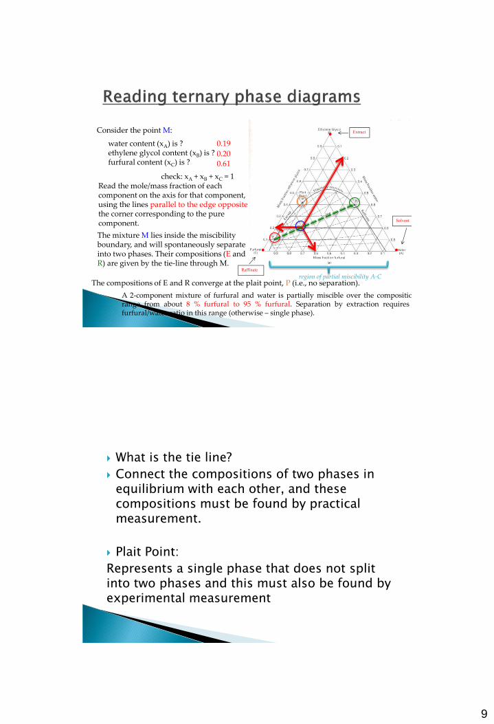
Consider the point M:
water content (xA) is ? ethylene glycol content (xB) is ? furfural content (xC) is ?
0.19
0.20
0.61
Read the mole/mass fraction of each component on the axis for that component, using the lines parallel to the edge opposite the corner corresponding to the pure component.
A 2-component mixture of furfural and water is partially miscible over the composition range from about 8 % furfural to 95 % furfural. Separation by extraction requires a furfural/water ratio in this range (otherwise – single phase).
The mixture M lies inside the miscibility boundary, and will spontaneously separate into two phases. Their compositions (E and R) are given by the tie-line through M.
The compositions of E and R converge at the plait point, P (i.e., no separation). region of partial miscibility A-C
check: xA + xB + xC = 1
•
•
•
Extract
Solvent
Raffinate
What is the tie line?
Connect the compositions of two phases in equilibrium with each other, and these compositions must be found by practical measurement.
Plait Point:
Represents a single phase that does not split into two phases and this must also be found by experimental measurement
10
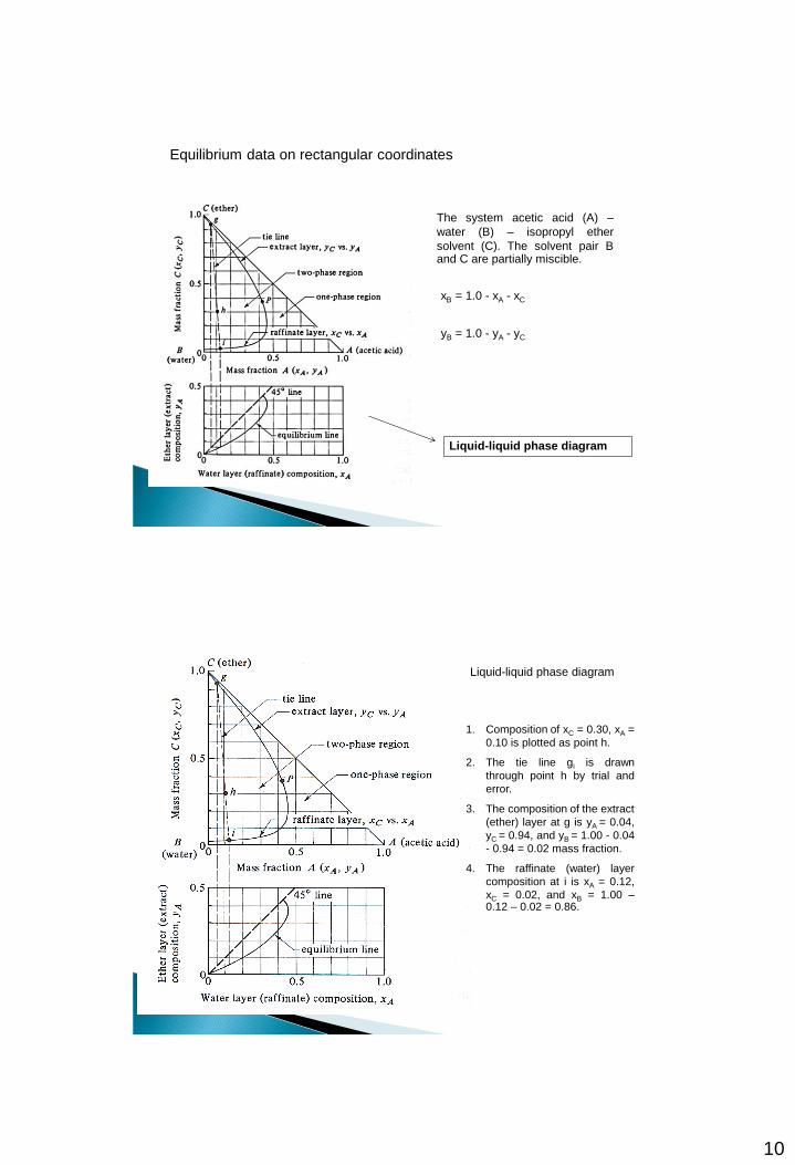
Equilibrium data on rectangular coordinates
The system acetic acid (A) –
water (B) – isopropyl ether
solvent (C). The solvent pair B and C are partially miscible.
xB = 1.0 - xA - xC
yB = 1.0 - yA - yC
Liquid-liquid phase diagram
1. Composition of xC = 0.30, xA =
0.10 is plotted as point h.
2. The tie line gi is drawn
through point h by trial and
error.
3. The composition of the extract
(ether) layer at g is yA = 0.04,
yC = 0.94, and yB = 1.00 - 0.04
- 0.94 = 0.02 mass fraction.
4. The raffinate (water) layer
composition at i is xA = 0.12,
xC = 0.02, and xB = 1.00 – 0.12 – 0.02 = 0.86.
Liquid-liquid phase diagram
11
• • •
•
•
•
•
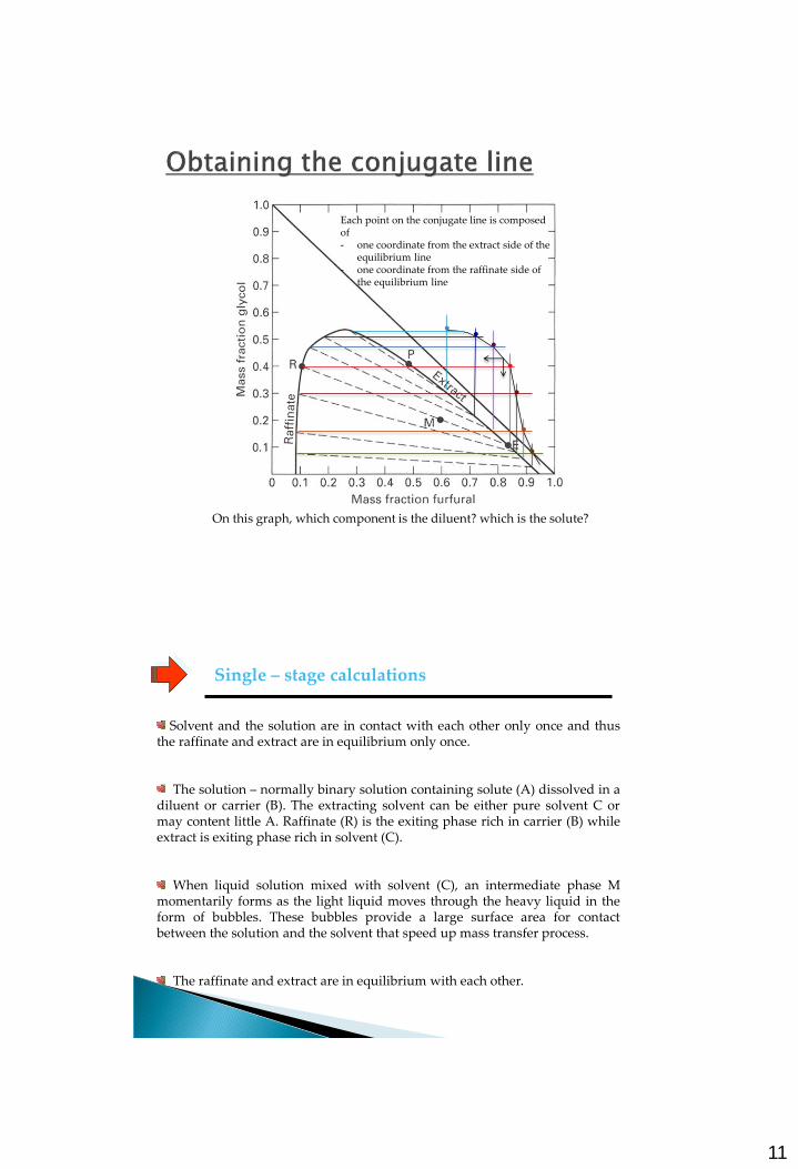
Each point on the conjugate line is composed of - one coordinate from the extract side of the
equilibrium line - one coordinate from the raffinate side of
the equilibrium line
On this graph, which component is the diluent? which is the solute?
Solvent and the solution are in contact with each other only once and thus the raffinate and extract are in equilibrium only once.
The solution – normally binary solution containing solute (A) dissolved in a diluent or carrier (B). The extracting solvent can be either pure solvent C or may content little A. Raffinate (R) is the exiting phase rich in carrier (B) while extract is exiting phase rich in solvent (C).
When liquid solution mixed with solvent (C), an intermediate phase M momentarily forms as the light liquid moves through the heavy liquid in the form of bubbles. These bubbles provide a large surface area for contact between the solution and the solvent that speed up mass transfer process.
The raffinate and extract are in equilibrium with each other.
Single – stage calculations
12
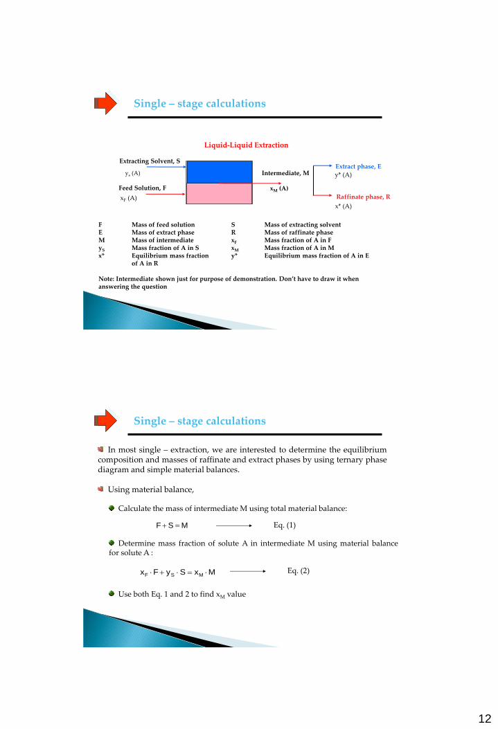
Single – stage calculations
Liquid-Liquid Extraction
y* (A) ys (A) Intermediate, M
Raffinate phase, R
x* (A)
Extract phase, E
xM (A)
F Mass of feed solution S Mass of extracting solvent E Mass of extract phase R Mass of raffinate phase M Mass of intermediate xF Mass fraction of A in F yS Mass fraction of A in S xM Mass fraction of A in M x* Equilibrium mass fraction y* Equilibrium mass fraction of A in E of A in R Note: Intermediate shown just for purpose of demonstration. Don’t have to draw it when answering the question
Feed Solution, F
xF (A)
Extracting Solvent, S
In most single – extraction, we are interested to determine the equilibrium composition and masses of raffinate and extract phases by using ternary phase diagram and simple material balances.
Using material balance,
Single – stage calculations
Calculate the mass of intermediate M using total material balance:
MSF Eq. (1)
Determine mass fraction of solute A in intermediate M using material balance for solute A :
MxSyFx MSF Eq. (2)
Use both Eq. 1 and 2 to find xM value
13
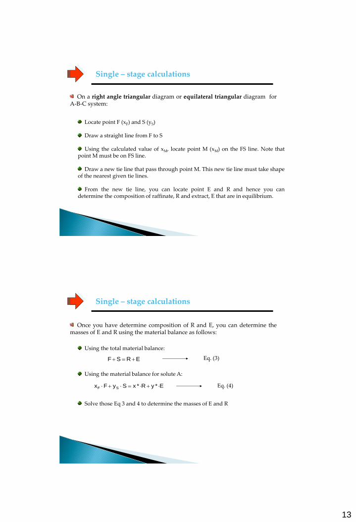
On a right angle triangular diagram or equilateral triangular diagram for A-B-C system:
Single – stage calculations
Locate point F (xF) and S (yS)
Draw a straight line from F to S Using the calculated value of xM, locate point M (xM) on the FS line. Note that
point M must be on FS line. Draw a new tie line that pass through point M. This new tie line must take shape
of the nearest given tie lines. From the new tie line, you can locate point E and R and hence you can
determine the composition of raffinate, R and extract, E that are in equilibrium.
Once you have determine composition of R and E, you can determine the masses of E and R using the material balance as follows:
Single – stage calculations
Using the total material balance:
Eq. (3) ERSF
Using the material balance for solute A:
EyRxSyFx SF ** Eq. (4)
Solve those Eq 3 and 4 to determine the masses of E and R
14
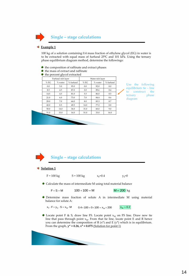
Example 1
Single – stage calculations
100 kg of a solution containing 0.4 mass fraction of ethylene glycol (EG) in water is to be extracted with equal mass of furfural 250C and 101 kPa. Using the ternary phase equilibrium diagram method, determine the followings:
the composition of raffinate and extract phases the mass of extract and raffinate the percent glycol extracted
Furfural rich layer Water rich layer
% EG % water % furfural % EG % water % furfural
0.0 5.0 95.0 0.0 92.0 8.0
8.5 4.5 87.0 2.0 89.6 8.4
14.5 4.5 81.0 5.5 86.0 8.5
21.0 6.0 73.0 7.0 84.4 8.6
29.0 7.0 64.0 8.0 83.3 8.7
42.0 8.5 49.5 14.0 77.2 8.8
50.0 14.0 36.0 31.0 60.0 9.0
51.0 33.0 16.0 51.0 33.0 16.0
Use the following equilibrium tie – line to construct the ternary phase diagram
Solution 1
Single – stage calculations
Calculate the mass of intermediate M using total material balance
F = 100 kg S = 100 kg xF=0.4 yS=0
MSF M100100 200M kg
Determine mass fraction of solute A in intermediate M using material balance for solute A:
MxSyFx MSF 200x100010040 M . 20xM .
Locate point F & S, draw line FS. Locate point xM on FS line. Draw new tie line that pass through point xM. From that tie line, locate point E and R hence you can determine the composition of R (x*) and E (y*) which is in equilibrium. From the graph, y* = 0.26, x* = 0.075 (Solution for point 1)
15
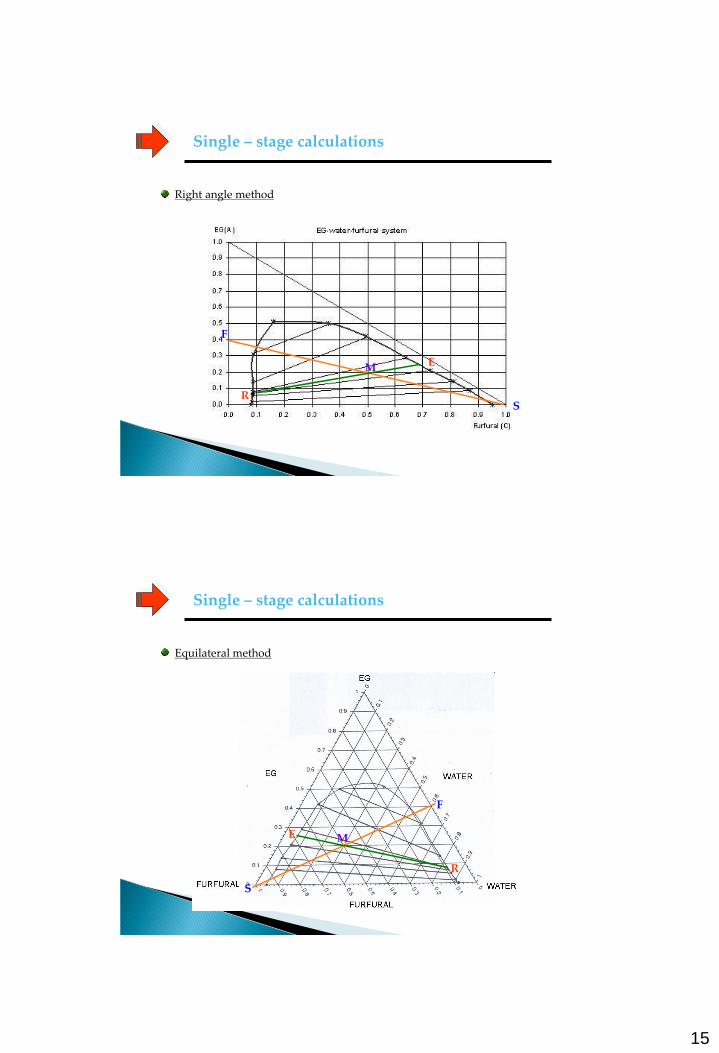
Single – stage calculations
Right angle method
F
S
M E
R
Single – stage calculations
Equilateral method
S
M E
R
F
16
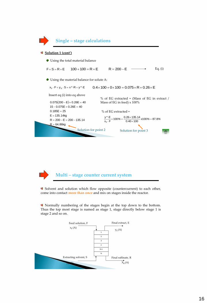
Solution 1 (cont’)
Single – stage calculations
Using the total material balance
Using the material balance for solute A:
ERSF ER100100 E200R Eq. (i)
EyRxSyFx SF ** E260R0750100010040 ...
Insert eq (i) into eq above
kg8664R
14135200E200R
kg14135E
25E1850
40E260E075015
40E260E2000750
.
.
.
.
..
..
Solution for point 2
% of EG extracted = (Mass of EG in extract / Mass of EG in feed) x 100%
%.%.
..%
*887100x
100400
14135260100
Fx
Ey
F
% of EG extracted =
Solution for point 3
Solvent and solution which flow opposite (countercurrent) to each other, come into contact more than once and mix on stages inside the reactor.
Normally numbering of the stages begin at the top down to the bottom. Thus the top most stage is named as stage 1, stage directly below stage 1 is stage 2 and so on.
Multi – stage counter current system
XR (A)
Final raffinate, R Extracting solvent, S
yS (A)
Final extract, E
xF (A)
Feed solution, F
1
2
3
n
N-1
N
yE (A)
17
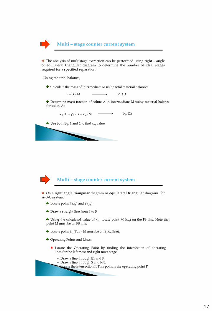
The analysis of multistage extraction can be performed using right – angle or equilateral triangular diagram to determine the number of ideal stages required for a specified separation. Using material balance,
Multi – stage counter current system
Calculate the mass of intermediate M using total material balance:
MSF Eq. (1)
Determine mass fraction of solute A in intermediate M using material balance for solute A :
MxSyFx MSF Eq. (2)
Use both Eq. 1 and 2 to find xM value
On a right angle triangular diagram or equilateral triangular diagram for A-B-C system:
Locate point F (xF) and S (yS)
Draw a straight line from F to S Using the calculated value of xM, locate point M (xM) on the FS line. Note that
point M must be on FS line. Locate point E1 (Point M must be on E1RN line).
Multi – stage counter current system
Operating Points and Lines.
Locate the Operating Point by finding the intersection of operating lines for the left most and right most stage.
Draw a line through E1 and F. Draw a line through S and RN. Locate the intersection P. This point is the operating point P.
18
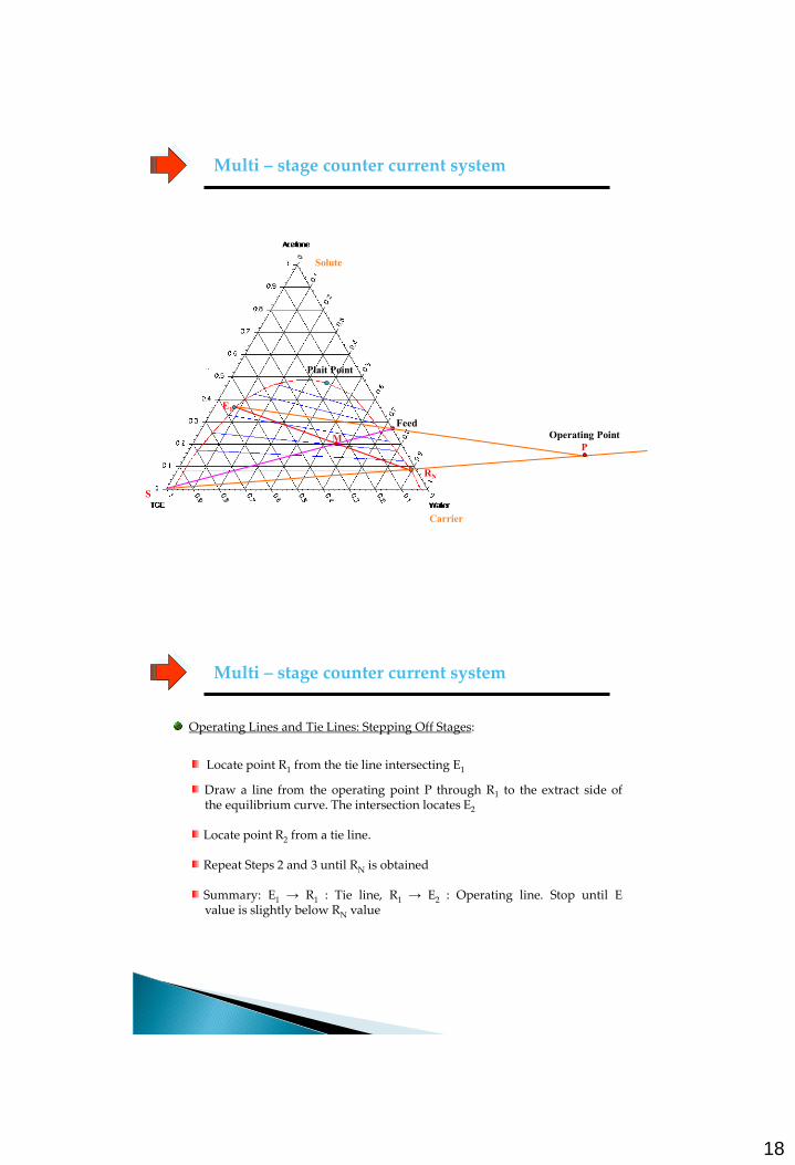
Multi – stage counter current system
Plait Point
Carrier
Solute
Feed
RN
M
E1
S
Operating Point
P
Multi – stage counter current system
Operating Lines and Tie Lines: Stepping Off Stages:
Locate point R1 from the tie line intersecting E1
Draw a line from the operating point P through R1 to the extract side of the equilibrium curve. The intersection locates E2
Locate point R2 from a tie line. Repeat Steps 2 and 3 until RN is obtained Summary: E1 → R1 : Tie line, R1 → E2 : Operating line. Stop until E
value is slightly below RN value
19
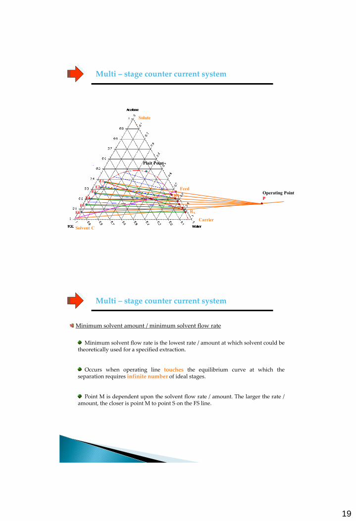
Multi – stage counter current system
Plait Point
Solvent C
Carrier
Solute
E1
R1
Feed
RN
E2
E3
E4
E5
E6
M
Operating Point
P
Minimum solvent amount / minimum solvent flow rate
Minimum solvent flow rate is the lowest rate / amount at which solvent could be theoretically used for a specified extraction.
Occurs when operating line touches the equilibrium curve at which the separation requires infinite number of ideal stages.
Point M is dependent upon the solvent flow rate / amount. The larger the rate / amount, the closer is point M to point S on the FS line.
Multi – stage counter current system
20
Multi – stage counter current system
On a right angle triangular diagram or equilateral triangular diagram for A-B-C system:
Locate point F (xF) and S (yS)
Draw a best tie line that originate from F. The intersection of this line with extract half – dome is point Emin (minimum extract flow rate / amount).
Draw a straight line from Emin to point R. The intersection of this line with
FS gives point Mmin. From point Mmin you can read the value of xmin. Use the value of xmin and material balance to calculate the Smin .
% Overall efficiency of multi – stage extraction column:
% Overall efficiency = (number of ideal stage / number of real stage) x 100%
Example 2
5300 kg/h of a solution containing 30% by weight of ethylene glycol (EG) in water is to be reduced to 4.5% (solvent free) by a continuous extraction in a countercurrent column using recycled furfural that contains 1.5% EG as the extracting solvent:
Determine the minimum solvent flow rate for the extraction above
If the solvent enters at 1.25 times the minimum solvent rate, how many ideal stages are required?
Determine the number of real stages if the overall efficiency of the column
is 60%
Multi – stage counter current system
21
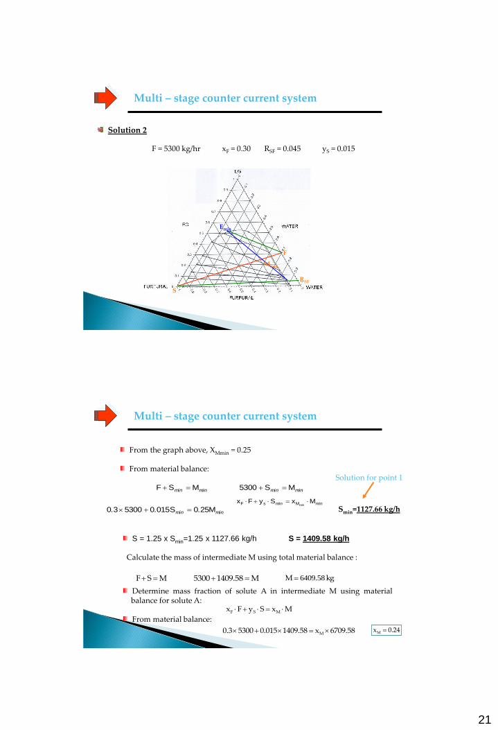
Solution 2
F = 5300 kg/hr xF = 0.30 RSF = 0.045 yS = 0.015
Multi – stage counter current system
F
S
Emin
RSF
Mmin
Multi – stage counter current system
From the graph above, XMmin = 0.25
From material balance:
minmin MSF minmin MS5300
minmin minMxSyFx MsF
minmin ... M250S0150530030 Smin=1127.66 kg/h
Solution for point 1
S = 1.25 x Smin=1.25 x 1127.66 kg/h S = 1409.58 kg/h
Calculate the mass of intermediate M using total material balance :
MSF M1409.585300 kg M 58.6409
Determine mass fraction of solute A in intermediate M using material balance for solute A:
From material balance:
MxSyFx MSF
6709.58x1409.580.01553000.3 M 0.24xM
22
Multi – stage counter current system
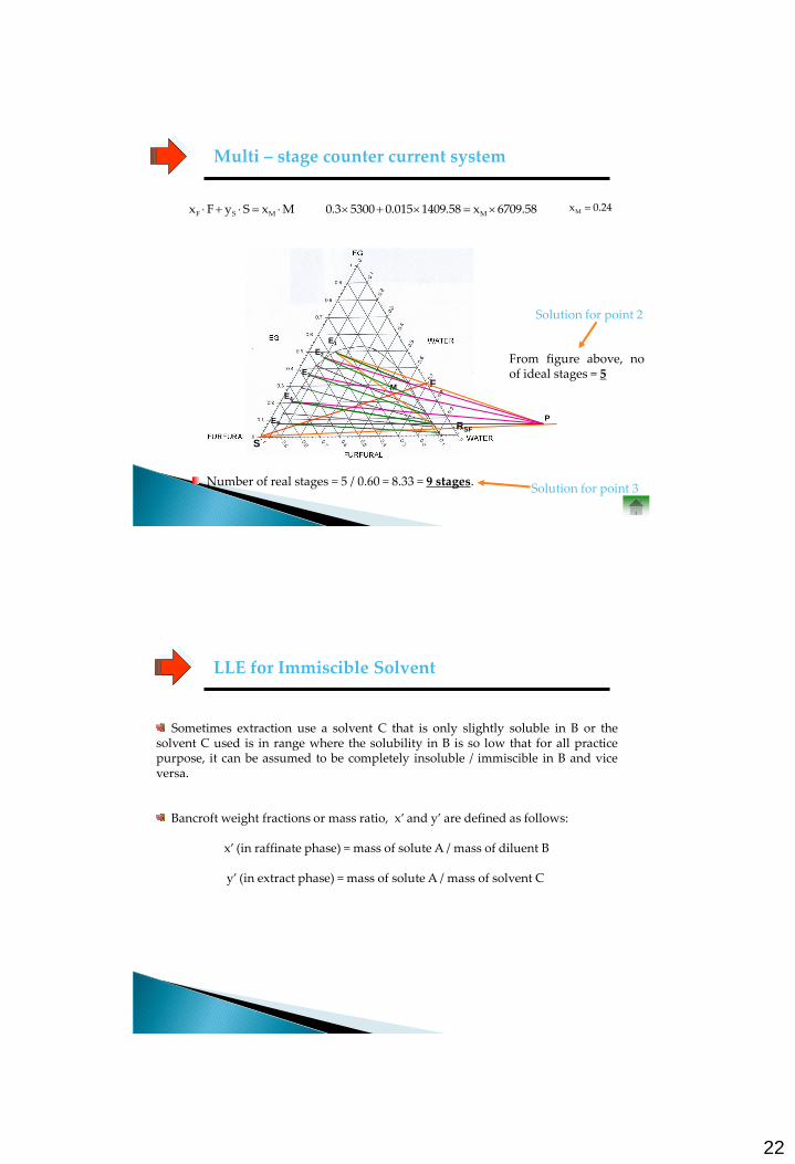
Solution for point 2
MxSyFx MSF 6709.58x1409.580.01553000.3 M 0.24xM
F
S
E1
RSF
M
P
E2
E3
E4
E5
From figure above, no of ideal stages = 5
Number of real stages = 5 / 0.60 = 8.33 = 9 stages. Solution for point 3
LLE for Immiscible Solvent
Sometimes extraction use a solvent C that is only slightly soluble in B or the solvent C used is in range where the solubility in B is so low that for all practice purpose, it can be assumed to be completely insoluble / immiscible in B and vice versa.
Bancroft weight fractions or mass ratio, x’ and y’ are defined as follows:
x’ (in raffinate phase) = mass of solute A / mass of diluent B
y’ (in extract phase) = mass of solute A / mass of solvent C
23
SINGLE STAGE CALCULATIONS
MULTISTAGE COUNTER CURRENT SYSTEM
LLE for Immiscible Solvent
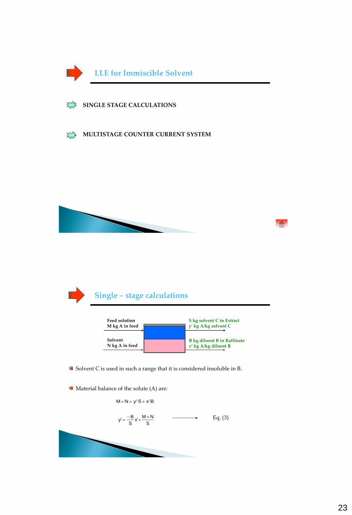
Solvent C is used in such a range that it is considered insoluble in B.
Material balance of the solute (A) are:
Feed solution M kg A in feed
S kg solvent C in Extract y’ kg A/kg solvent C
Solvent N kg A in feed
B kg diluent B in Raffinate x’ kg A/kg diluent B
BxSyNM ''
S
NMx
S
By
'' Eq. (3)
Single – stage calculations
24
Example 3
Single – stage calculations
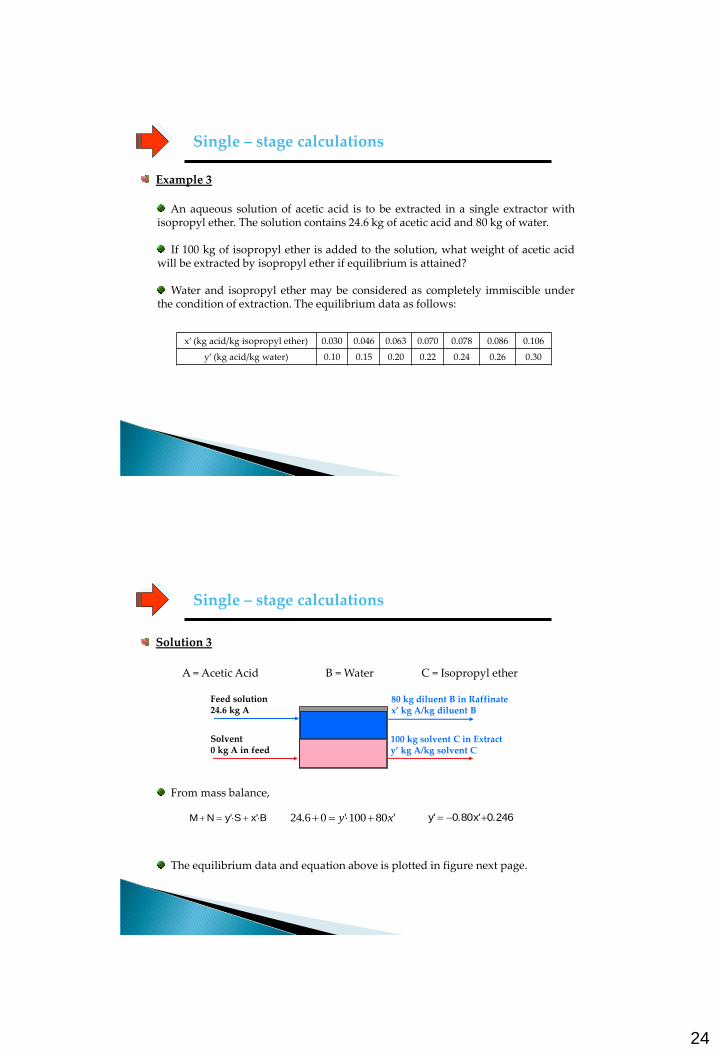
An aqueous solution of acetic acid is to be extracted in a single extractor with isopropyl ether. The solution contains 24.6 kg of acetic acid and 80 kg of water.
If 100 kg of isopropyl ether is added to the solution, what weight of acetic acid
will be extracted by isopropyl ether if equilibrium is attained? Water and isopropyl ether may be considered as completely immiscible under
the condition of extraction. The equilibrium data as follows:
x’ (kg acid/kg isopropyl ether) 0.030 0.046 0.063 0.070 0.078 0.086 0.106
y’ (kg acid/kg water) 0.10 0.15 0.20 0.22 0.24 0.26 0.30
A = Acetic Acid B = Water C = Isopropyl ether
Single – stage calculations
From mass balance,
Feed solution 24.6 kg A
100 kg solvent C in Extract y’ kg A/kg solvent C
Solvent 0 kg A in feed
80 kg diluent B in Raffinate x’ kg A/kg diluent B
BxSyNM '' '80100'06.24 xy 2460x800y .'.'
The equilibrium data and equation above is plotted in figure next page.
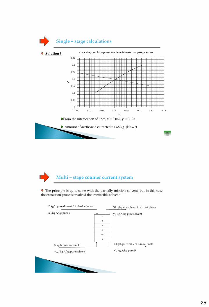
Solution 3
25
Single – stage calculations
Solution 3 x' - y' diagram for system acetic acid-water-isopropyl ether
0
0.05
0.1
0.15
0.2
0.25
0.3
0.35
0 0.02 0.04 0.06 0.08 0.1 0.12 0.14
x'
y'
From the intersection of lines, x’ = 0.062, y’ = 0.195 Amount of acetic acid extracted = 19.5 kg (How?)
The principle is quite same with the partially miscible solvent, but in this case the extraction process involved the immiscible solvent.
Multi – stage counter current system
B kg/h pure diluent B in feed solution x’2 kg A/kg pure B
B kg/h pure diluent B in raffinate x’n kg A/kg pure B
S kg/h pure solvent C yn+1’ kg A/kg pure solvent
S kg/h pure solvent in extract phase y’2 kg A/kg pure solvent
1
2
3
n
N-1
N
26
Countercurrent-Stage Extraction with Immiscible Liquids
1
1
1
1
0
0
1111 y
yV
x
xL
y
yV
x
xL
N
N
N
N
1
1
1
1
0
0
1111 y
yV
x
xL
y
yV
x
xL
n
n
n
n
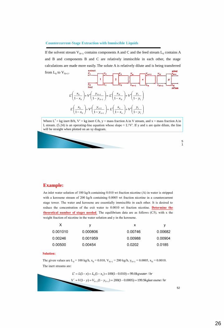
If the solvent stream VN+1 contains components A and C and the feed stream L0 contains A
and B and components B and C are relatively immiscible in each other, the stage
calculations are made more easily. The solute A is relatively dilute and is being transferred
from L0 to VN+1.
Where Lʹ = kg inert B/h, Vʹ = kg inert C/h, y = mass fraction A in V stream, and x = mass fraction A in
L stream. (5.24) is an operating-line equation whose slope ≈ Lʹ/Vʹ. If y and x are quite dilute, the line
will be straight when plotted on an xy diagram.
51
Example:
An inlet water solution of 100 kg/h containing 0.010 wt fraction nicotine (A) in water is stripped with a kerosene stream of 200 kg/h containing 0.0005 wt fraction nicotine in a countercurrent stage tower. The water and kerosene are essentially immiscible in each other. It is desired to reduce the concentration of the exit water to 0.0010 wt fraction nicotine. Determine the theoretical number of stages needed. The equilibrium data are as follows (C5), with x the
weight fraction of nicotine in the water solution and y in the kerosene.
52
Solution:
The given values are L0 = 100 kg/h, x0 = 0.010, VN+1 = 200 kg/h, yN+1 = 0.0005, xN = 0.0010.
The inert streams are:
hrwaterkgxLxLL /0.99)010.01(100)1()1( 00
hrosenekgyVyVV NN /ker9.199)0005.01(200)1()1( 11
/
27
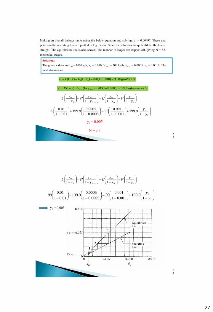
Making an overall balance on A using the below equation and solving, y1 = 0.00497. These end points on the operating line are plotted in Fig. below. Since the solutions are quite dilute, the line is straight. The equilibrium line is also shown. The number of stages are stepped off, giving N = 3.8
theoretical stages.
53
1
1
1
1
0
0
1111 y
yV
x
xL
y
yV
x
xL
N
N
N
N
Solution: The given values are L0 = 100 kg/h, x0 = 0.010, VN+1 = 200 kg/h, yN+1 = 0.0005, xN = 0.0010. The
inert streams are
hrwaterkgxLxLL /0.99)010.01(100)1()1( 00
hrosenekgyVyVV NN /ker9.199)0005.01(200)1()1( 11
/
1
1
19.199
001.01
001.099
0005.01
0005.09.199
01.01
01.099
y
y
y1 = 0.005
N = 3.7
54
1
1
19.199
001.01
001.099
0005.01
0005.09.199
01.01
01.099
y
y
y1 = 0.005
1
1
1
1
0
0
1111 y
yV
x
xL
y
yV
x
xL
N
N
N
N

28
Liquid – liquid extraction equipment
Two main classes of solvent – extraction equipment: 1) Vessels in which mechanical agitation is provided for mixing 2) Vessels in which the mixing is done by the flow of the fluid themselves. The extraction equipment can be operated batch or continuous.
Liquid – liquid extraction equipment
Mixer – Settlers for Extraction
A mechanical mixer is often used to provide intimate contact between the two liquid phases – to provide efficient mass transfer. One phase is usually dispersed into the other in the form of small droplet. In figure 12.6 – 1(a) for typical mixer settler, mixer or agitator is entirely separate from the settler. The feed of aqueous phase and organic phase are mixed in the mixer, and then the mixed phases are separated in the settler. In figure 12.6 – 1(b) for combined mixer settler, sometimes used in extraction of uranium salts or copper salts from aqueous solution.
29
Liquid – liquid extraction equipment
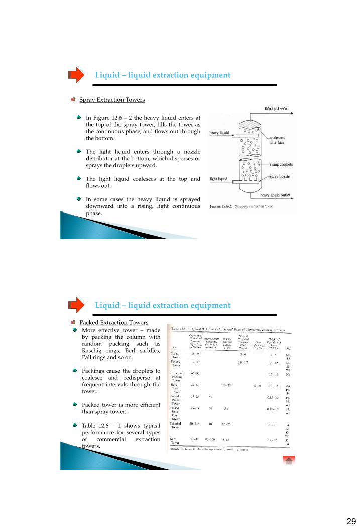
Spray Extraction Towers
In Figure 12.6 – 2 the heavy liquid enters at the top of the spray tower, fills the tower as the continuous phase, and flows out through the bottom. The light liquid enters through a nozzle distributor at the bottom, which disperses or sprays the droplets upward. The light liquid coalesces at the top and flows out. In some cases the heavy liquid is sprayed downward into a rising, light continuous phase.
Liquid – liquid extraction equipment
Packed Extraction Towers More effective tower – made by packing the column with random packing such as Raschig rings, Berl saddles, Pall rings and so on Packings cause the droplets to coalesce and redisperse at frequent intervals through the tower. Packed tower is more efficient than spray tower. Table 12.6 – 1 shows typical performance for several types of commercial extraction towers.


![AIChE Journal Volume 1 Issue 4 1955 [Doi 10.1002%2Faic.690010428] C. LeRoy Carpenter; Donald F. Othmer -- Entrainment Removal by a Wire-mesh Separator](https://static.fdocuments.us/doc/165x107/577cc0bc1a28aba71190eb56/aiche-journal-volume-1-issue-4-1955-doi-1010022faic690010428-c-leroy.jpg)