
Chapter 19faculty.chemeketa.edu/csekafet/ELT133/CH19.pdf•A Xs C decreases, V out also decreases....
94
Chapter 19 Basic Filters
Transcript of Chapter 19faculty.chemeketa.edu/csekafet/ELT133/CH19.pdf•A Xs C decreases, V out also decreases....
Chapter 19Basic Filters

Objectives
• Analyze the operation of RC and RL low-pass filters
• Analyze the operation of RC and RL high-pass filters
• Analyze the operation of band-pass filters• Analyze the operation of band-stop filters• Investigate a real-world application of
filters
Low-Pass Filters
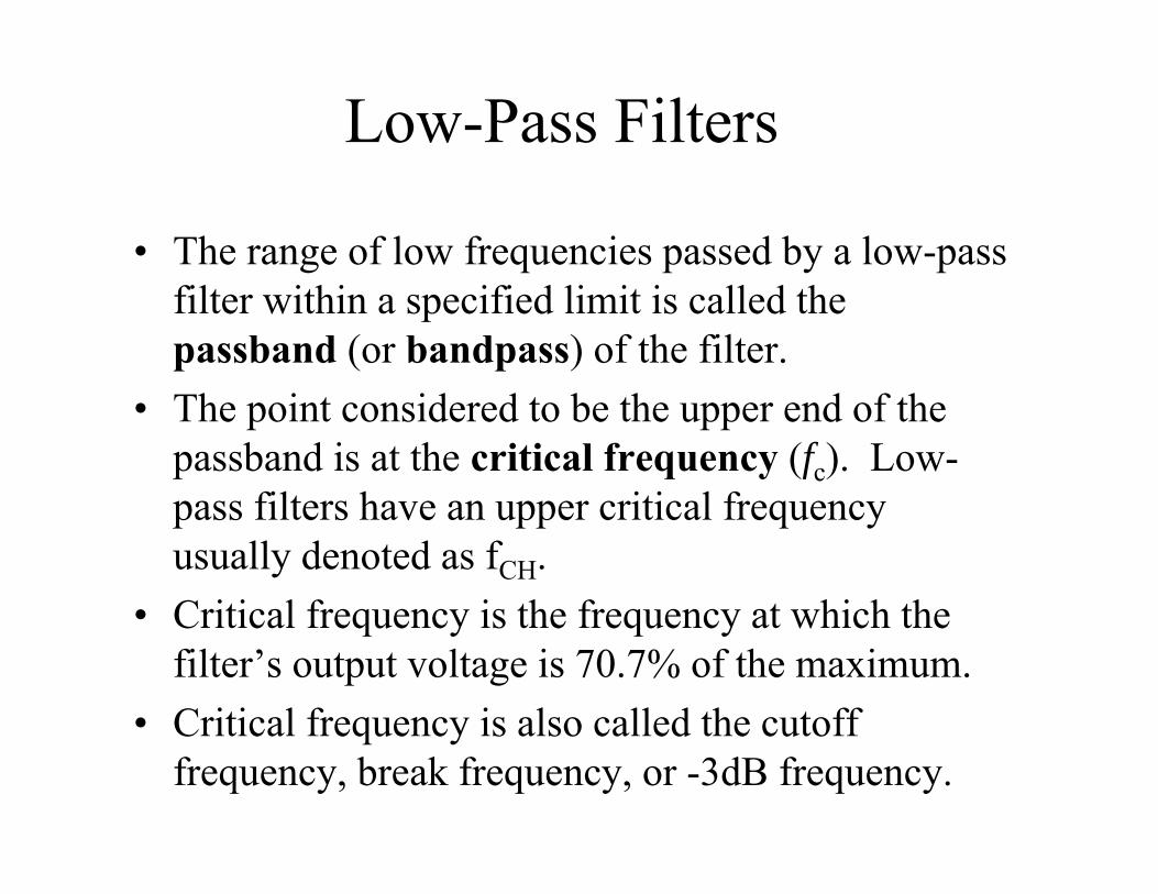
• The range of low frequencies passed by a low-pass filter within a specified limit is called the passband (or bandpass) of the filter.
• The point considered to be the upper end of the passband is at the critical frequency (fc). Low-pass filters have an upper critical frequency usually denoted as fCH.
• Critical frequency is the frequency at which the filter’s output voltage is 70.7% of the maximum.
• Critical frequency is also called the cutoff frequency, break frequency, or -3dB frequency.
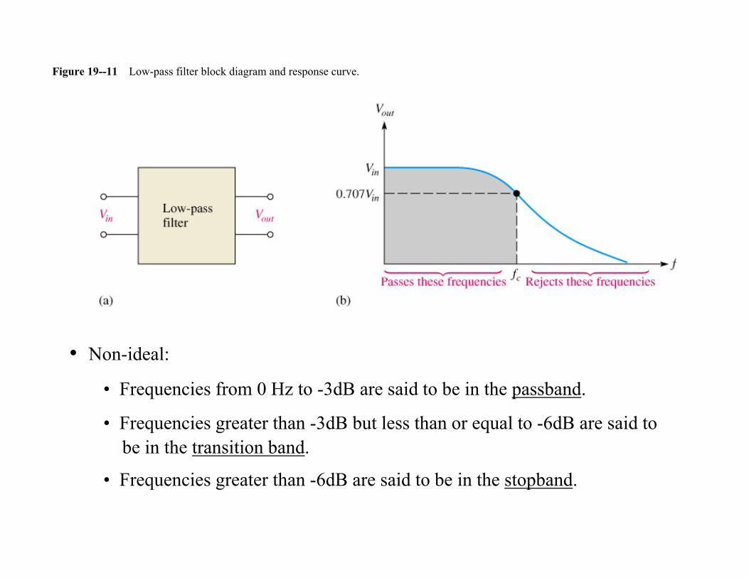
Figure 19--11 Low-pass filter block diagram and response curve.
• Non-ideal:
• Frequencies from 0 Hz to -3dB are said to be in the passband.
• Frequencies greater than -3dB but less than or equal to -6dB are said to be in the transition band.
• Frequencies greater than -6dB are said to be in the stopband.
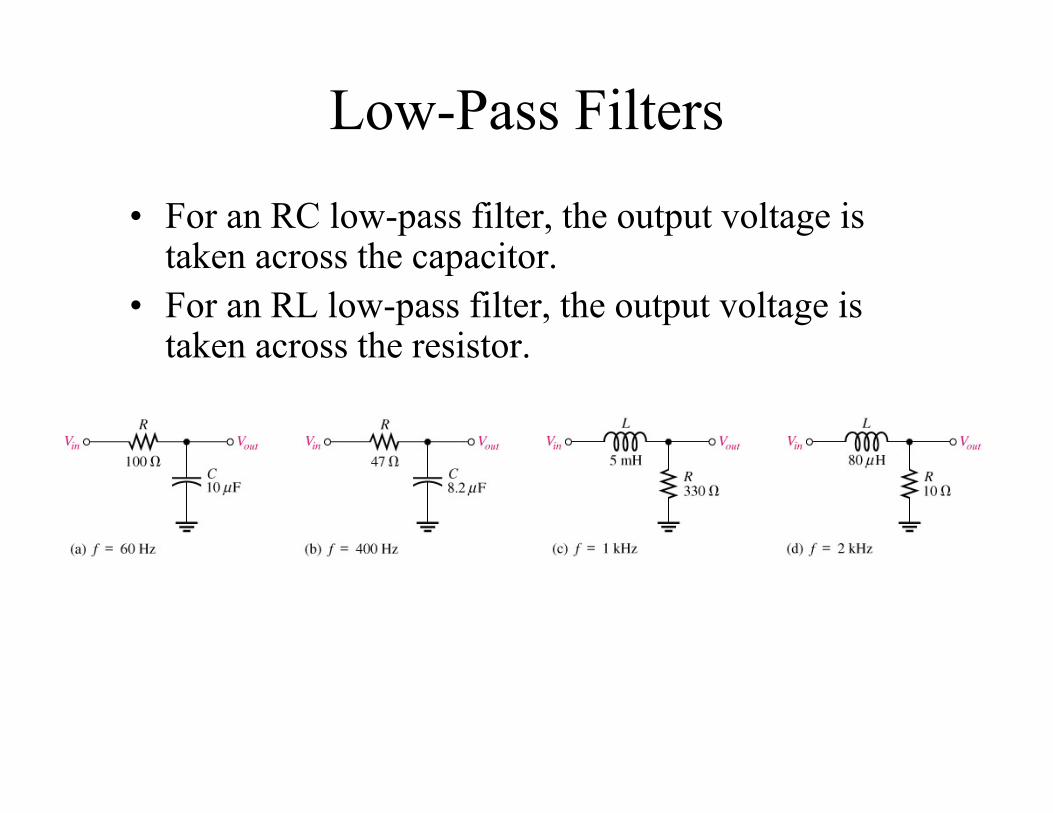
Low-Pass Filters
• For an RC low-pass filter, the output voltage is taken across the capacitor.
• For an RL low-pass filter, the output voltage is taken across the resistor.
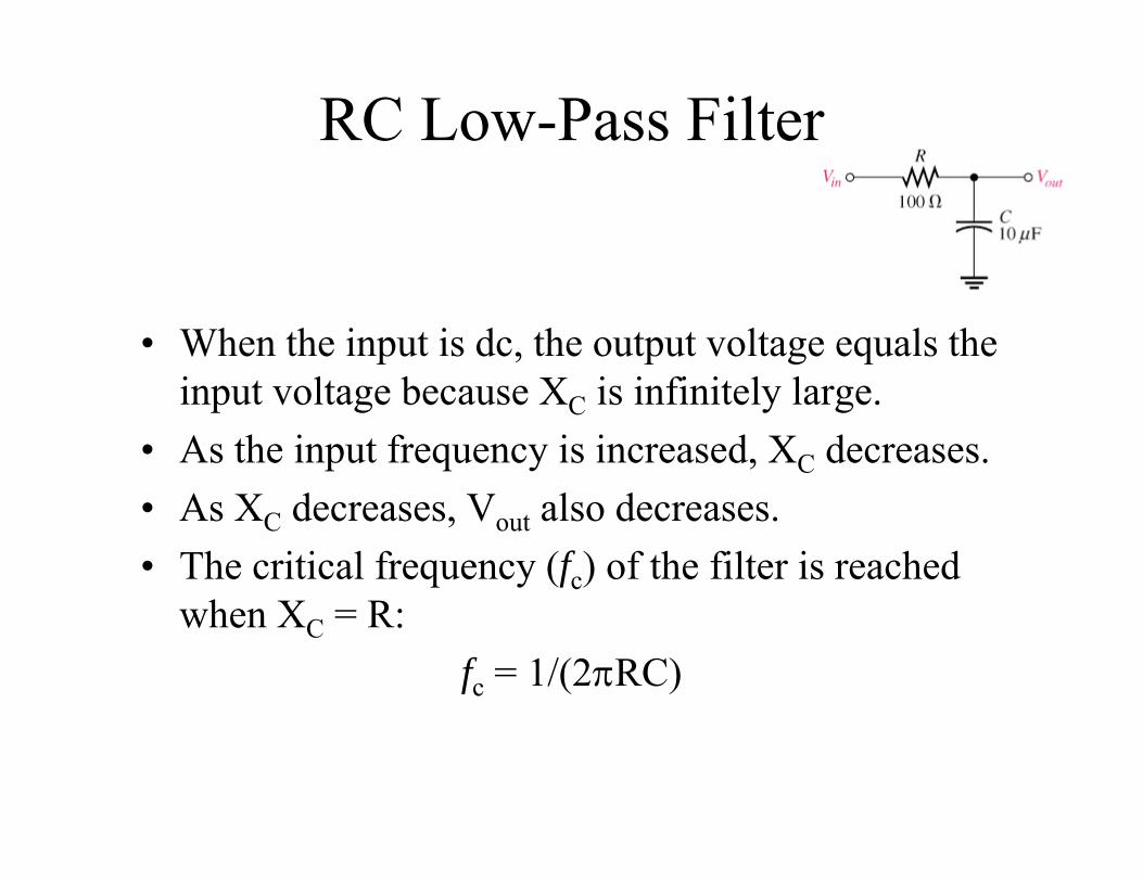
RC Low-Pass Filter
• When the input is dc, the output voltage equals the input voltage because XC is infinitely large.
• As the input frequency is increased, XC decreases.• As XC decreases, Vout also decreases.• The critical frequency (fc) of the filter is reached
when XC = R:fc = 1/(2RC)
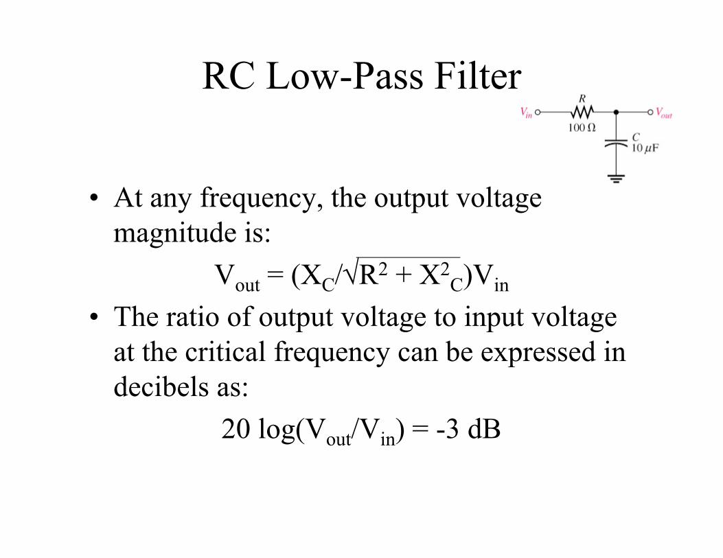
RC Low-Pass Filter
• At any frequency, the output voltage magnitude is:
Vout = (XC/R2 + X2C)Vin
• The ratio of output voltage to input voltage at the critical frequency can be expressed in decibels as:
20 log(Vout/Vin) = -3 dB
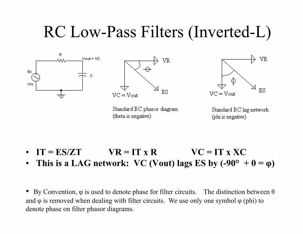
RC Low-Pass Filters (Inverted-L)
• IT = ES/ZT VR = IT x R VC = IT x XC• This is a LAG network: VC (Vout) lags ES by (-90° + θ = φ)
• By Convention, φ is used to denote phase for filter circuits. The distinction between θand φ is removed when dealing with filter circuits. We use only one symbol φ (phi) to denote phase on filter phasor diagrams.
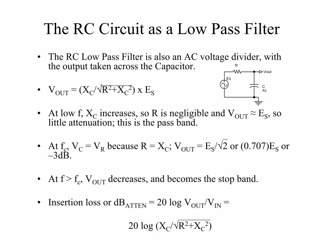
The RC Circuit as a Low Pass Filter• The RC Low Pass Filter is also an AC voltage divider, with
the output taken across the Capacitor.
• VOUT = (XC/√R2+XC2) x ES
• At low f, XC increases, so R is negligible and VOUT ≈ ES, so little attenuation; this is the pass band.
• At fc, VC = VR because R = XC; VOUT = ES/√2 or (0.707)ES or –3dB.
• At f > fc, VOUT decreases, and becomes the stop band.
• Insertion loss or dBATTEN = 20 log VOUT/VIN =
20 log (XC/√R2+XC2)
Vout
CXc
R
Es
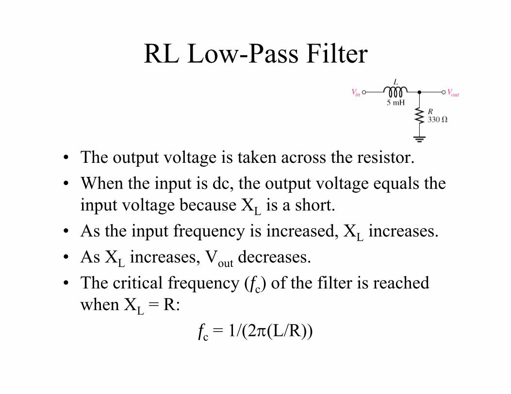
RL Low-Pass Filter
• The output voltage is taken across the resistor.• When the input is dc, the output voltage equals the
input voltage because XL is a short.• As the input frequency is increased, XL increases.• As XL increases, Vout decreases.• The critical frequency (fc) of the filter is reached
when XL = R:fc = 1/(2(L/R))
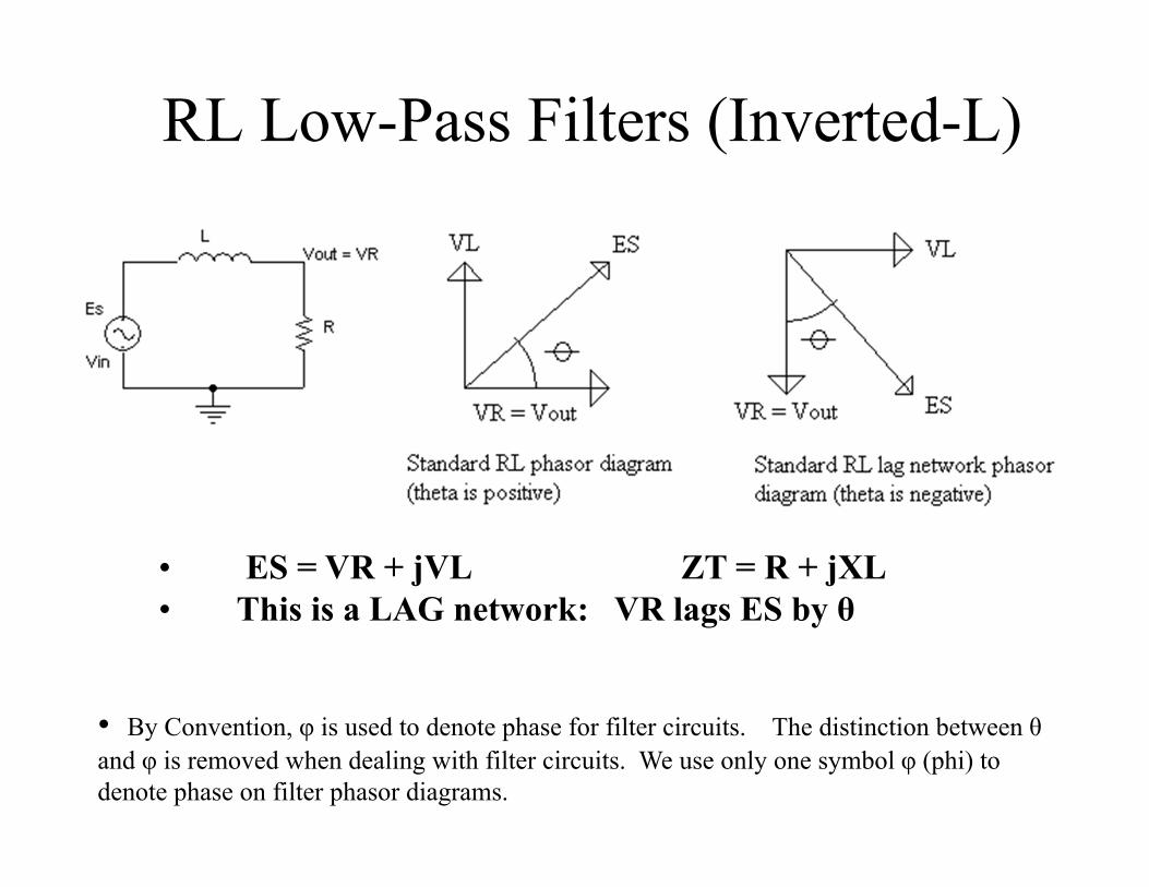
RL Low-Pass Filters (Inverted-L)
• ES = VR + jVL ZT = R + jXL• This is a LAG network: VR lags ES by θ
• By Convention, φ is used to denote phase for filter circuits. The distinction between θand φ is removed when dealing with filter circuits. We use only one symbol φ (phi) to denote phase on filter phasor diagrams.
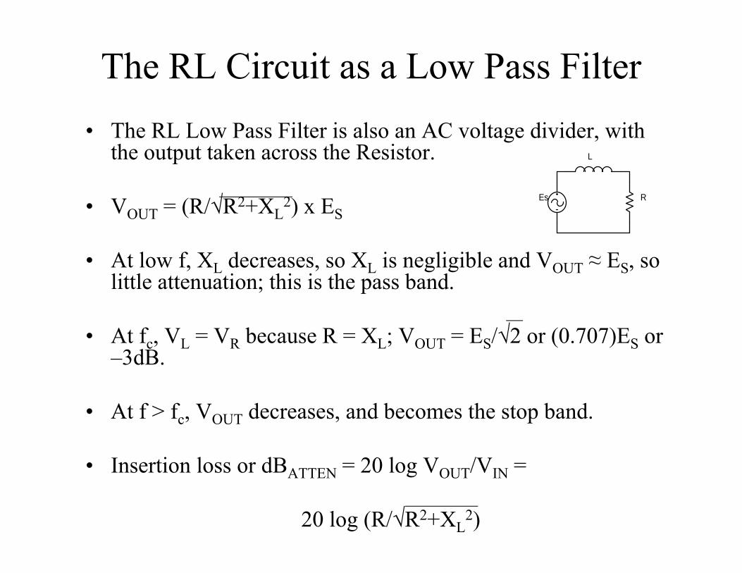
The RL Circuit as a Low Pass Filter• The RL Low Pass Filter is also an AC voltage divider, with
the output taken across the Resistor.
• VOUT = (R/√R2+XL2) x ES
• At low f, XL decreases, so XL is negligible and VOUT ≈ ES, so little attenuation; this is the pass band.
• At fc, VL = VR because R = XL; VOUT = ES/√2 or (0.707)ES or –3dB.
• At f > fc, VOUT decreases, and becomes the stop band.
• Insertion loss or dBATTEN = 20 log VOUT/VIN =
20 log (R/√R2+XL2)
R
L
Es
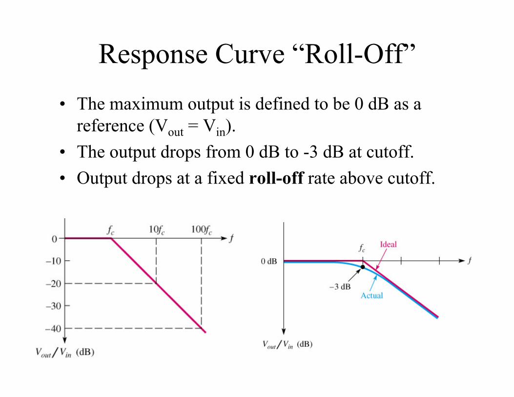
Response Curve “Roll-Off”• The maximum output is defined to be 0 dB as a
reference (Vout = Vin).• The output drops from 0 dB to -3 dB at cutoff.• Output drops at a fixed roll-off rate above cutoff.
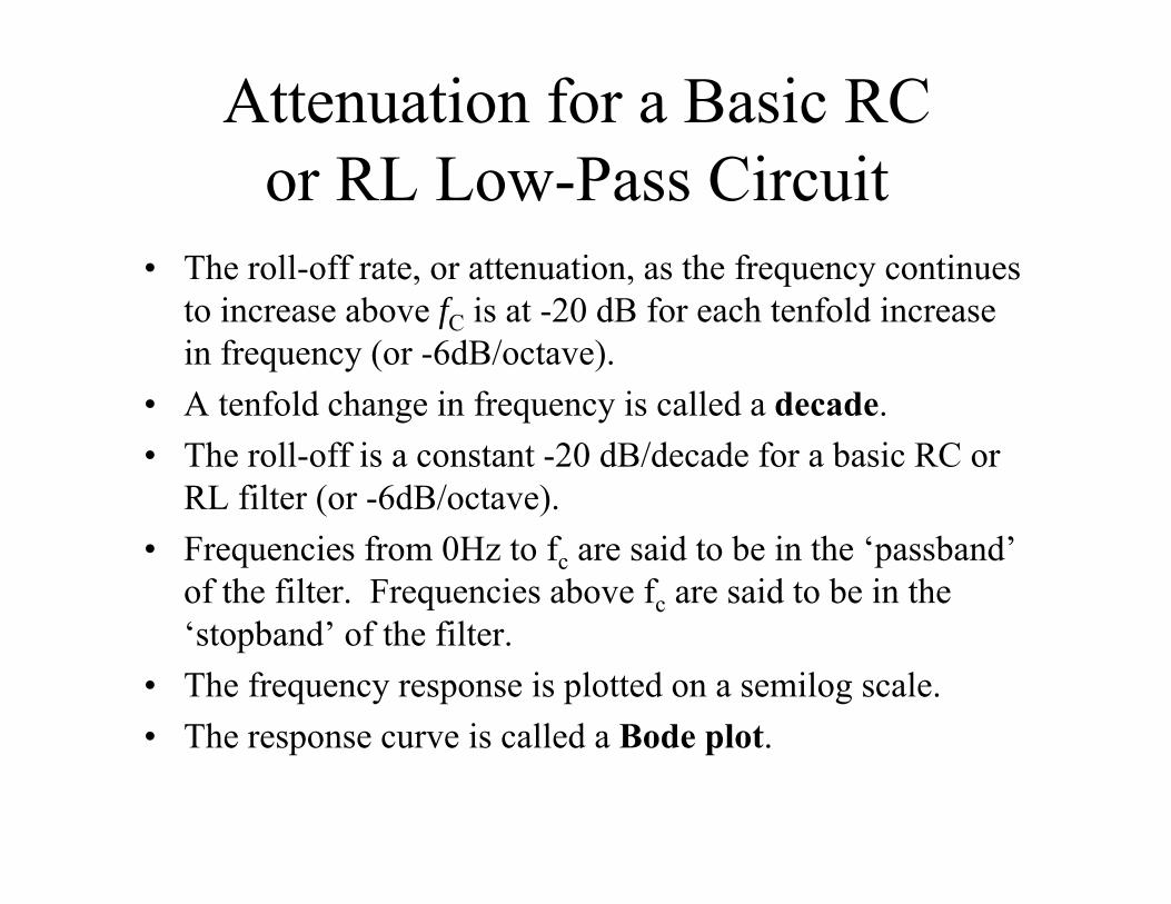
Attenuation for a Basic RC or RL Low-Pass Circuit
• The roll-off rate, or attenuation, as the frequency continues to increase above fC is at -20 dB for each tenfold increase in frequency (or -6dB/octave).
• A tenfold change in frequency is called a decade.• The roll-off is a constant -20 dB/decade for a basic RC or
RL filter (or -6dB/octave).• Frequencies from 0Hz to fc are said to be in the ‘passband’
of the filter. Frequencies above fc are said to be in the ‘stopband’ of the filter.
• The frequency response is plotted on a semilog scale.• The response curve is called a Bode plot.
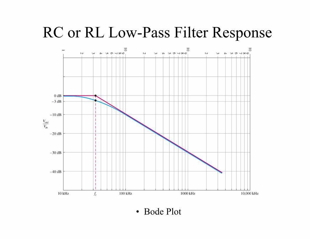
RC or RL Low-Pass Filter Response
• Bode Plot
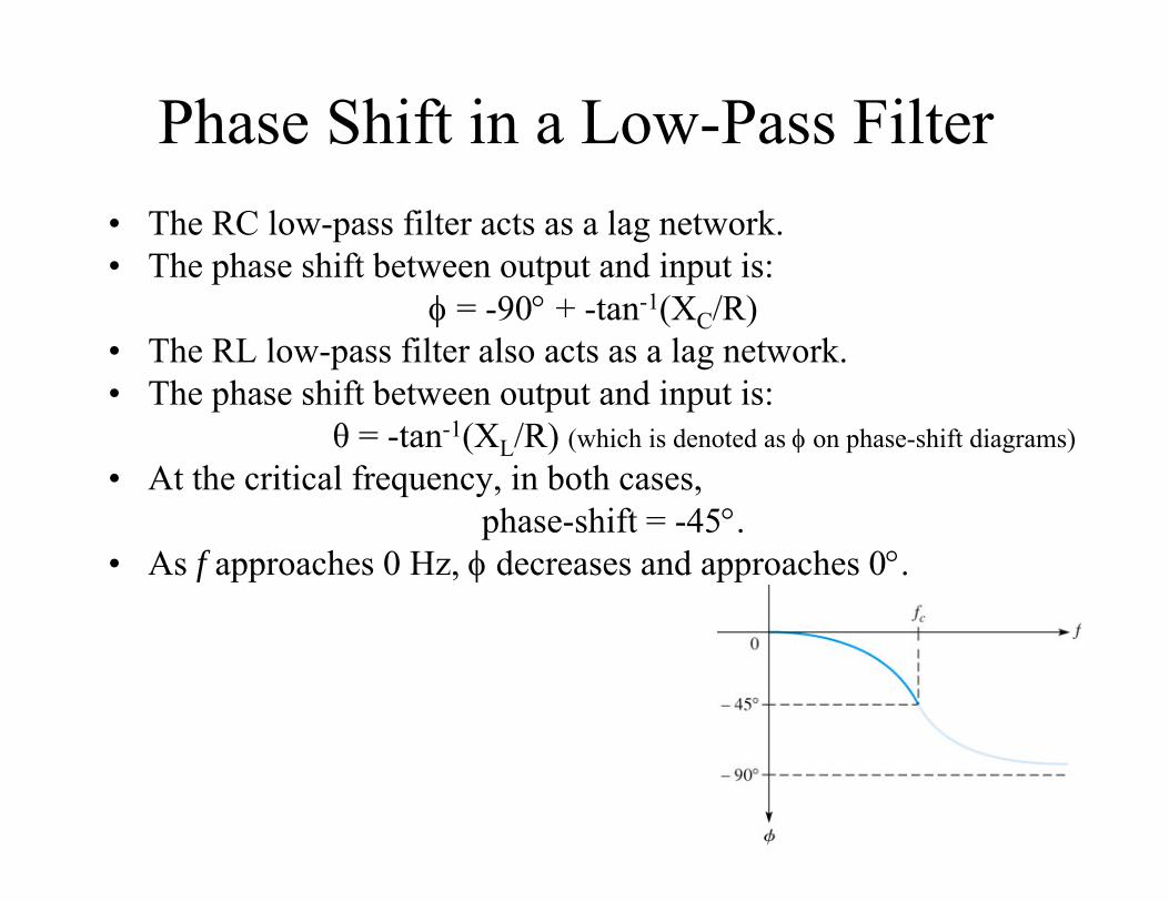
Phase Shift in a Low-Pass Filter• The RC low-pass filter acts as a lag network.• The phase shift between output and input is:
= -90 + -tan-1(XC/R)• The RL low-pass filter also acts as a lag network.• The phase shift between output and input is:
θ = -tan-1(XL/R) (which is denoted as on phase-shift diagrams)• At the critical frequency, in both cases,
phase-shift = -45.• As f approaches 0 Hz, decreases and approaches 0.
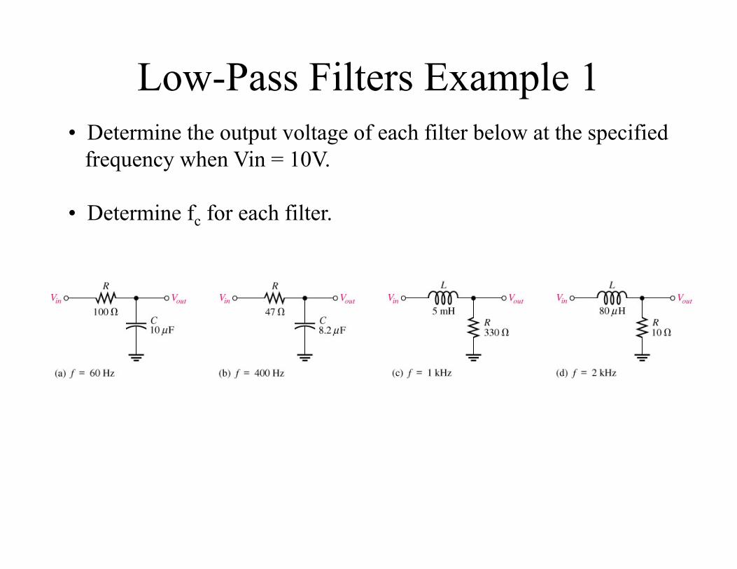
Low-Pass Filters Example 1• Determine the output voltage of each filter below at the specified
frequency when Vin = 10V.
• Determine fc for each filter.
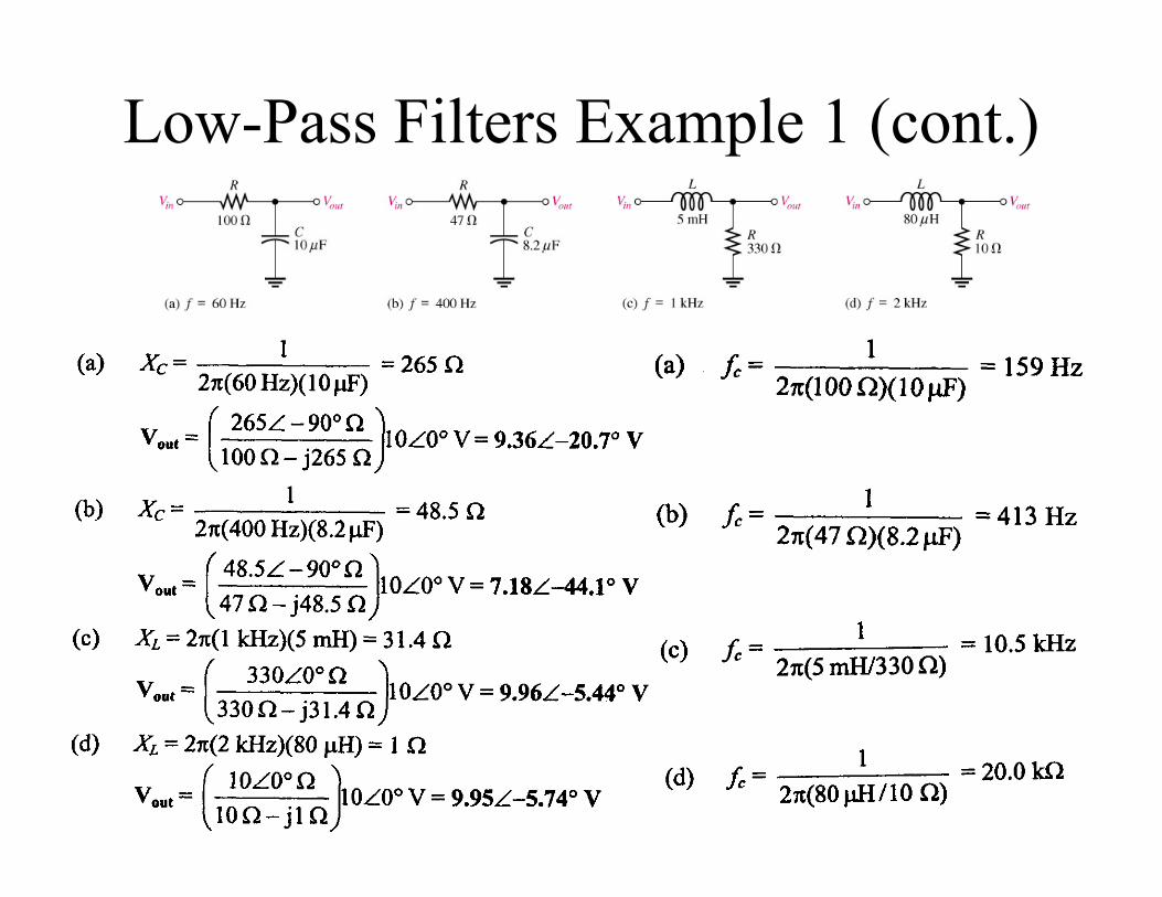
Low-Pass Filters Example 1 (cont.)
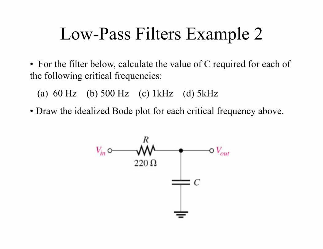
Low-Pass Filters Example 2• For the filter below, calculate the value of C required for each of the following critical frequencies:
(a) 60 Hz (b) 500 Hz (c) 1kHz (d) 5kHz
• Draw the idealized Bode plot for each critical frequency above.
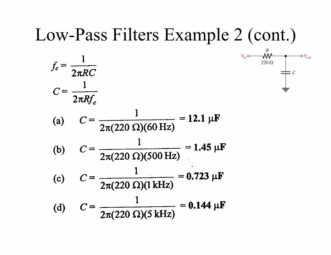
Low-Pass Filters Example 2 (cont.)
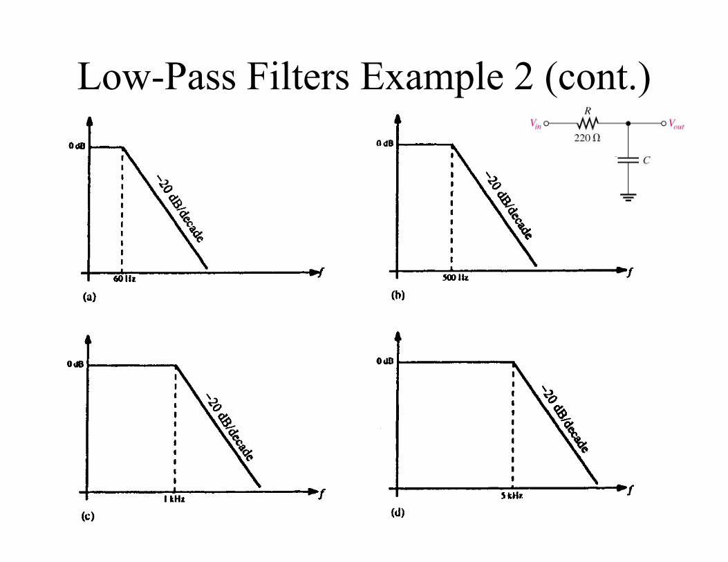
Low-Pass Filters Example 2 (cont.)
The Order Of A Filter
• Filters are often expressed with respect to the roll-off rate designated as the ‘number of poles’ or the filter order.
• “Poles” are defined as the number of capacitors or inductors used in a filter. There are some exceptions to this rule. More on this later!!!
• Each pole introduces a -20dB/decade roll-off rate. For example, a two-pole filter or second order filter will have a -40dB/decade roll-off rate.
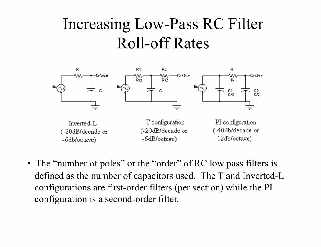
Increasing Low-Pass RC Filter Roll-off Rates
• The “number of poles” or the “order” of RC low pass filters is defined as the number of capacitors used. The T and Inverted-L configurations are first-order filters (per section) while the PI configuration is a second-order filter.
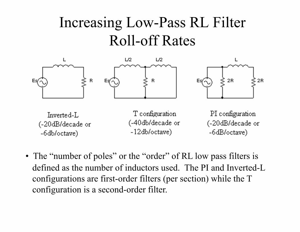
Increasing Low-Pass RL Filter Roll-off Rates
• The “number of poles” or the “order” of RL low pass filters is defined as the number of inductors used. The PI and Inverted-L configurations are first-order filters (per section) while the T configuration is a second-order filter.
High-Pass Filters
• A high-pass filter allows signals with higher frequencies to pass from input to output while rejecting lower frequencies.
• The range of high frequencies passed by a high-pass filter within a specified limit is called the passband (or bandpass) of the filter.
• The frequency considered to be the lower end of the passband is called the critical frequency fc or fCH.
• The critical frequency has an output which is 70.7% of the maximum.
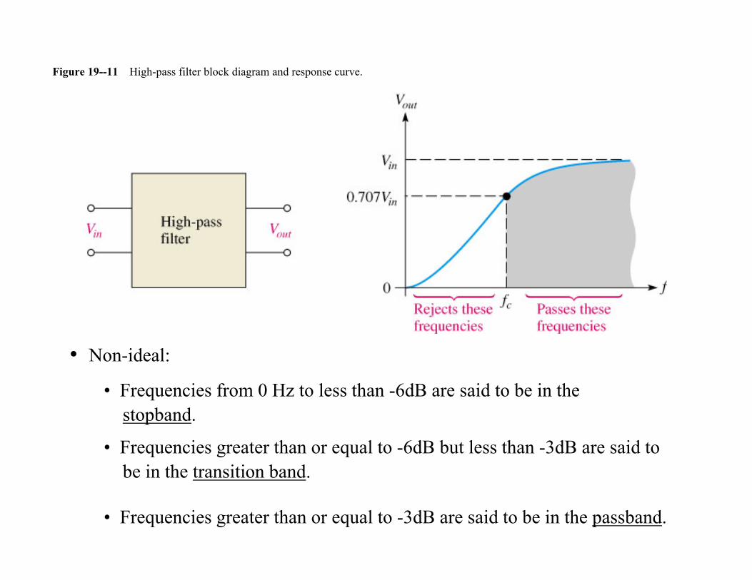
Figure 19--11 High-pass filter block diagram and response curve.
• Non-ideal:
• Frequencies from 0 Hz to less than -6dB are said to be in the stopband.
• Frequencies greater than or equal to -6dB but less than -3dB are said to be in the transition band.
• Frequencies greater than or equal to -3dB are said to be in the passband.
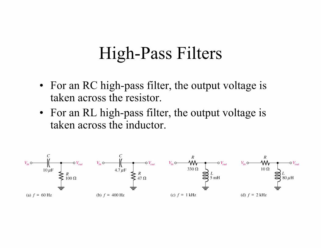
High-Pass Filters
• For an RC high-pass filter, the output voltage is taken across the resistor.
• For an RL high-pass filter, the output voltage is taken across the inductor.
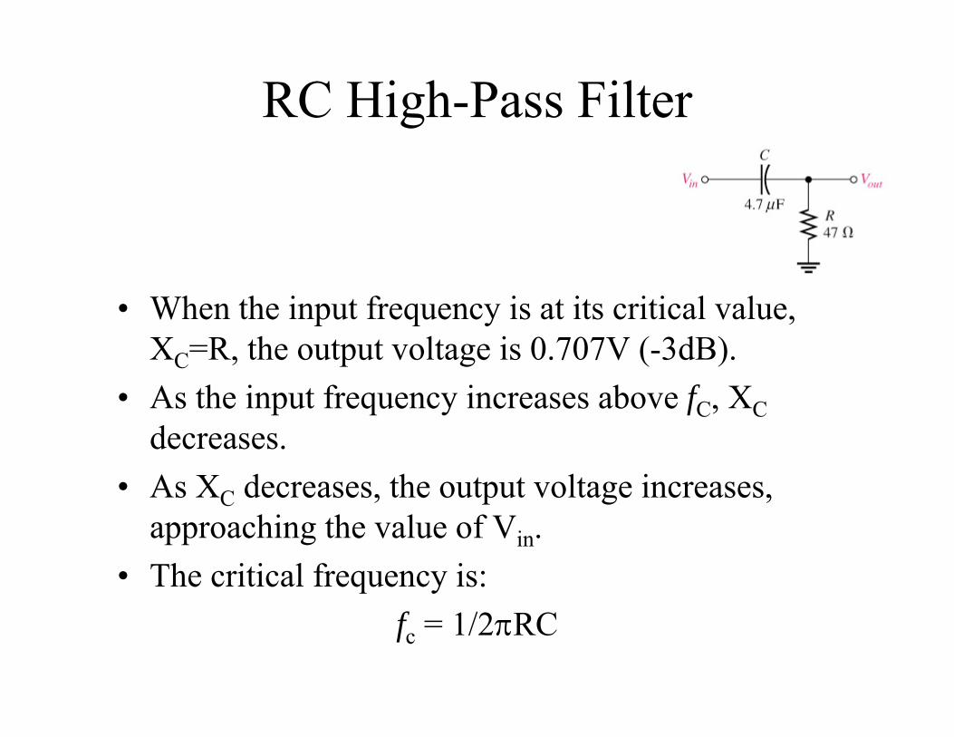
RC High-Pass Filter
• When the input frequency is at its critical value, XC=R, the output voltage is 0.707V (-3dB).
• As the input frequency increases above fC, XCdecreases.
• As XC decreases, the output voltage increases, approaching the value of Vin.
• The critical frequency is:fc = 1/2RC
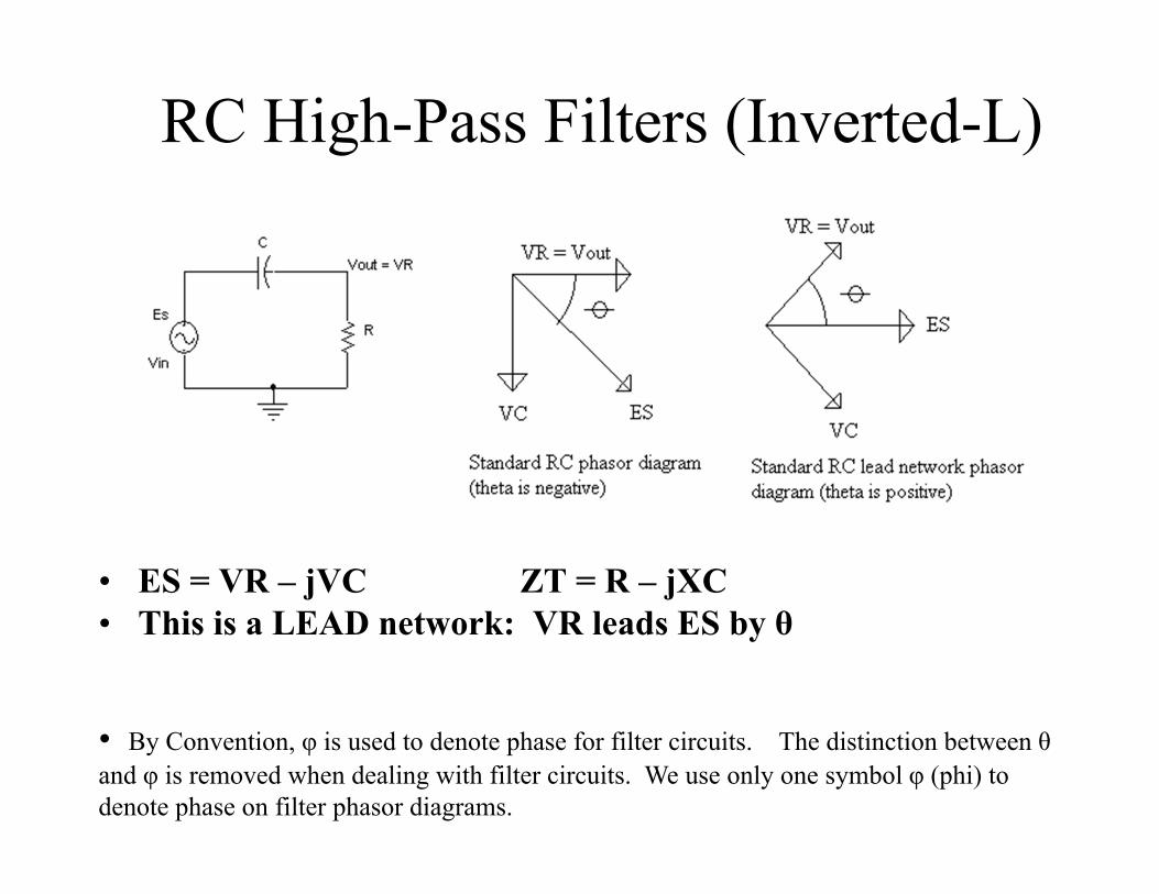
RC High-Pass Filters (Inverted-L)
• ES = VR – jVC ZT = R – jXC• This is a LEAD network: VR leads ES by θ
• By Convention, φ is used to denote phase for filter circuits. The distinction between θand φ is removed when dealing with filter circuits. We use only one symbol φ (phi) to denote phase on filter phasor diagrams.
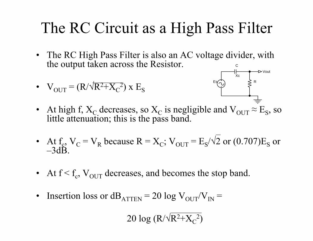
The RC Circuit as a High Pass Filter• The RC High Pass Filter is also an AC voltage divider, with
the output taken across the Resistor.
• VOUT = (R/√R2+XC2) x ES
• At high f, XC decreases, so XC is negligible and VOUT ≈ ES, so little attenuation; this is the pass band.
• At fc, VC = VR because R = XC; VOUT = ES/√2 or (0.707)ES or –3dB.
• At f < fc, VOUT decreases, and becomes the stop band.
• Insertion loss or dBATTEN = 20 log VOUT/VIN =
20 log (R/√R2+XC2)
Es R
C
XcVout
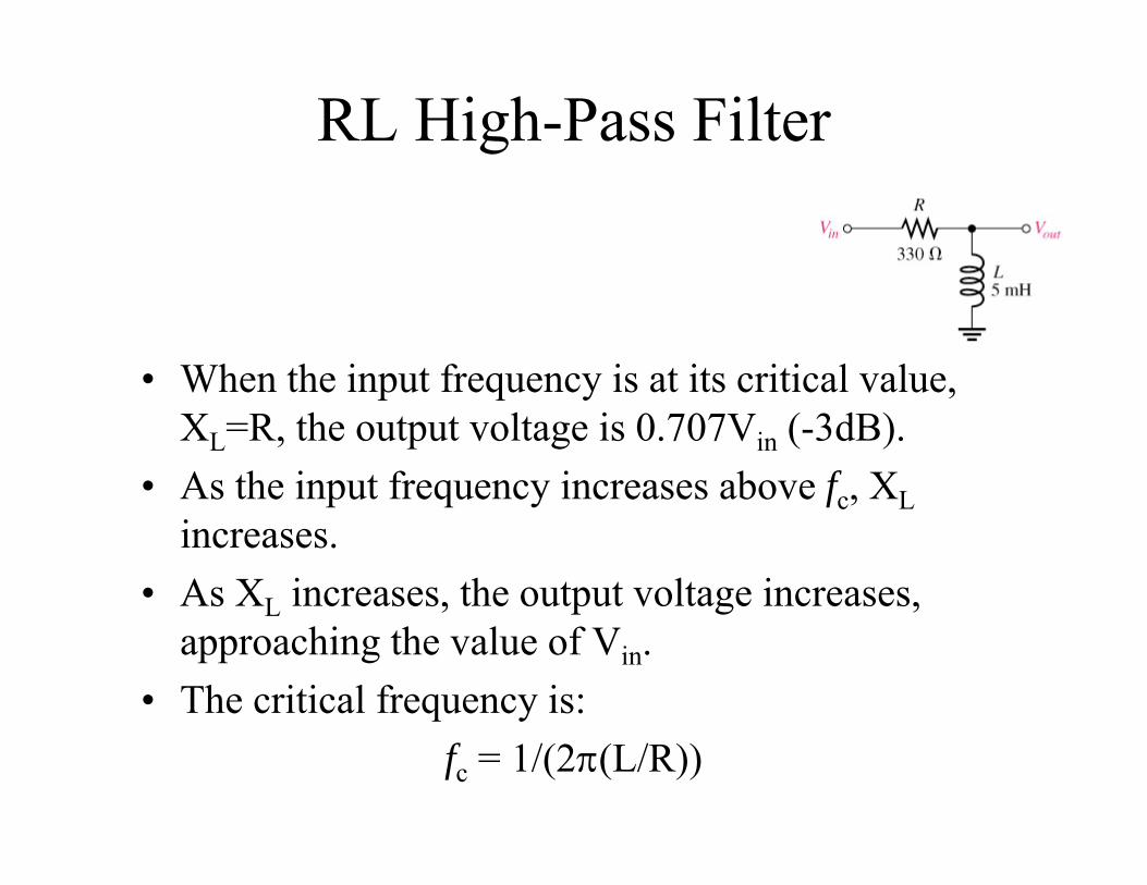
RL High-Pass Filter
• When the input frequency is at its critical value, XL=R, the output voltage is 0.707Vin (-3dB).
• As the input frequency increases above fc, XLincreases.
• As XL increases, the output voltage increases, approaching the value of Vin.
• The critical frequency is:fc = 1/(2(L/R))
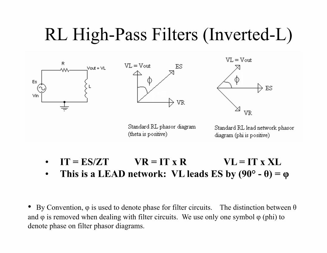
RL High-Pass Filters (Inverted-L)
• IT = ES/ZT VR = IT x R VL = IT x XL• This is a LEAD network: VL leads ES by (90° - θ) = φ
• By Convention, φ is used to denote phase for filter circuits. The distinction between θand φ is removed when dealing with filter circuits. We use only one symbol φ (phi) to denote phase on filter phasor diagrams.

The RL Circuit as a High-Pass Filter• The RL High Pass Filter is also an AC voltage divider, with
the output taken across the Inductor.
• VOUT = (XL/√R2+XL2) x ES
• At high f, XL increases, so R is negligible and VOUT ≈ ES, so little attenuation; this is the pass band.
• At fc, VL = VR because R = XL; VOUT = ES/√2 or (0.707)ES or –3dB.
• At f < fc, VOUT decreases, and becomes the stop band.
• Insertion loss or dBATTEN = 20 log VOUT/VIN =
20 log (XL/√R2+XL2)
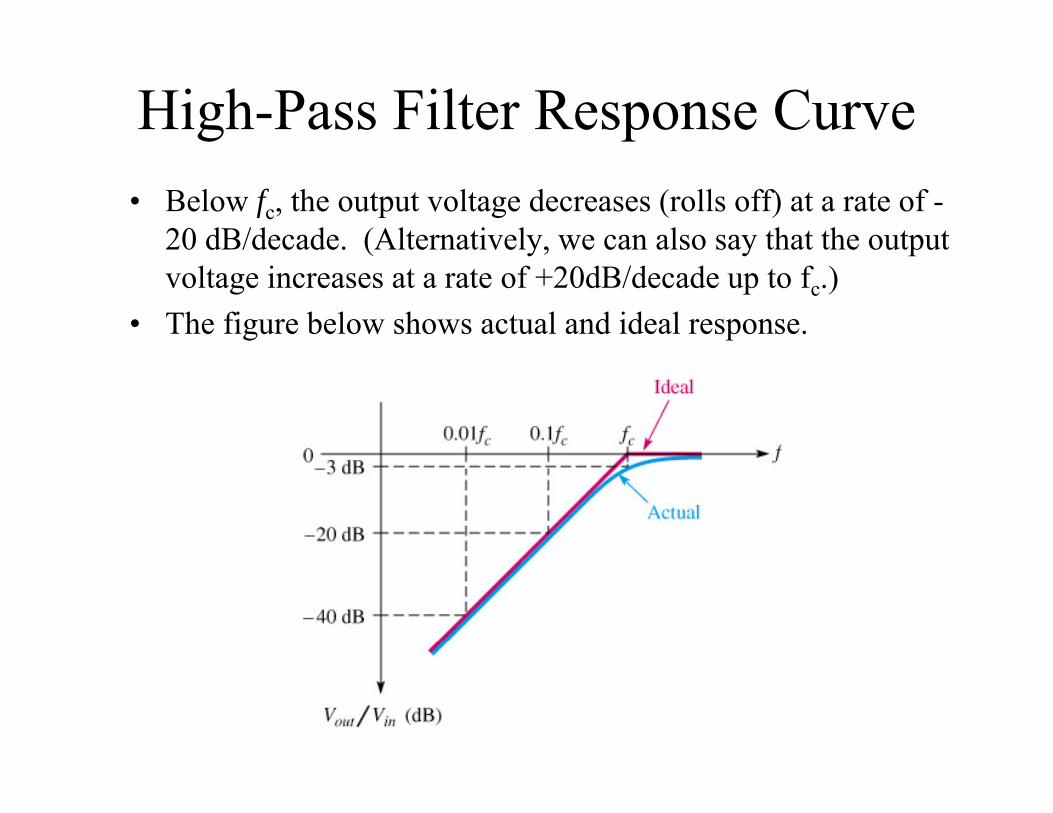
High-Pass Filter Response Curve• Below fc, the output voltage decreases (rolls off) at a rate of -
20 dB/decade. (Alternatively, we can also say that the output voltage increases at a rate of +20dB/decade up to fc.)
• The figure below shows actual and ideal response.
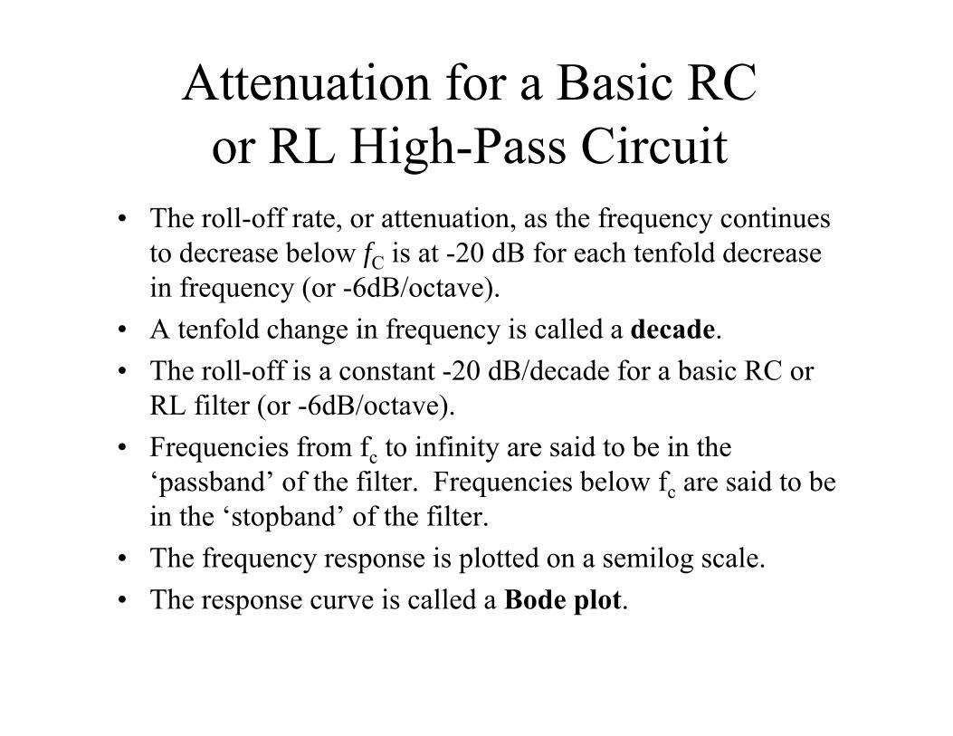
Attenuation for a Basic RC or RL High-Pass Circuit
• The roll-off rate, or attenuation, as the frequency continues to decrease below fC is at -20 dB for each tenfold decrease in frequency (or -6dB/octave).
• A tenfold change in frequency is called a decade.• The roll-off is a constant -20 dB/decade for a basic RC or
RL filter (or -6dB/octave).• Frequencies from fc to infinity are said to be in the
‘passband’ of the filter. Frequencies below fc are said to be in the ‘stopband’ of the filter.
• The frequency response is plotted on a semilog scale.• The response curve is called a Bode plot.
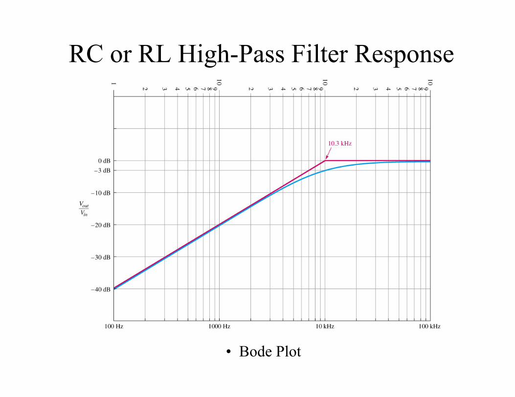
RC or RL High-Pass Filter Response
• Bode Plot
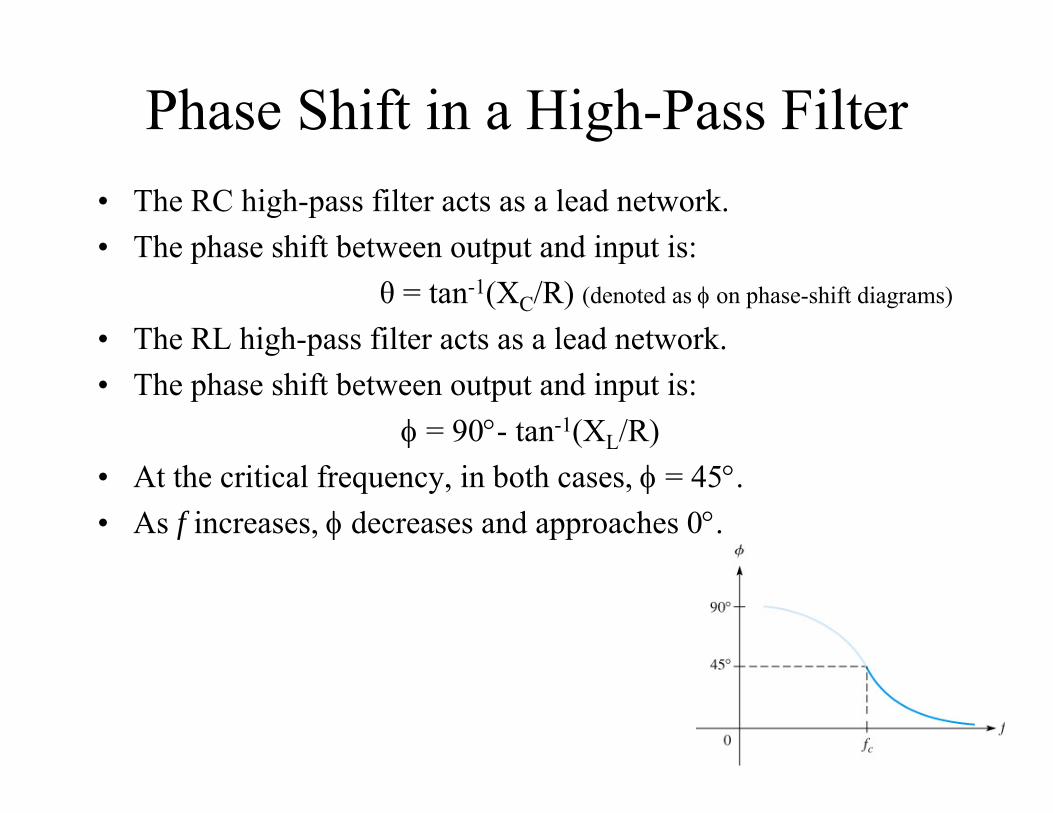
Phase Shift in a High-Pass Filter• The RC high-pass filter acts as a lead network.• The phase shift between output and input is:
θ = tan-1(XC/R) (denoted as on phase-shift diagrams)
• The RL high-pass filter acts as a lead network.• The phase shift between output and input is:
= 90- tan-1(XL/R)• At the critical frequency, in both cases, = 45.• As f increases, decreases and approaches 0.
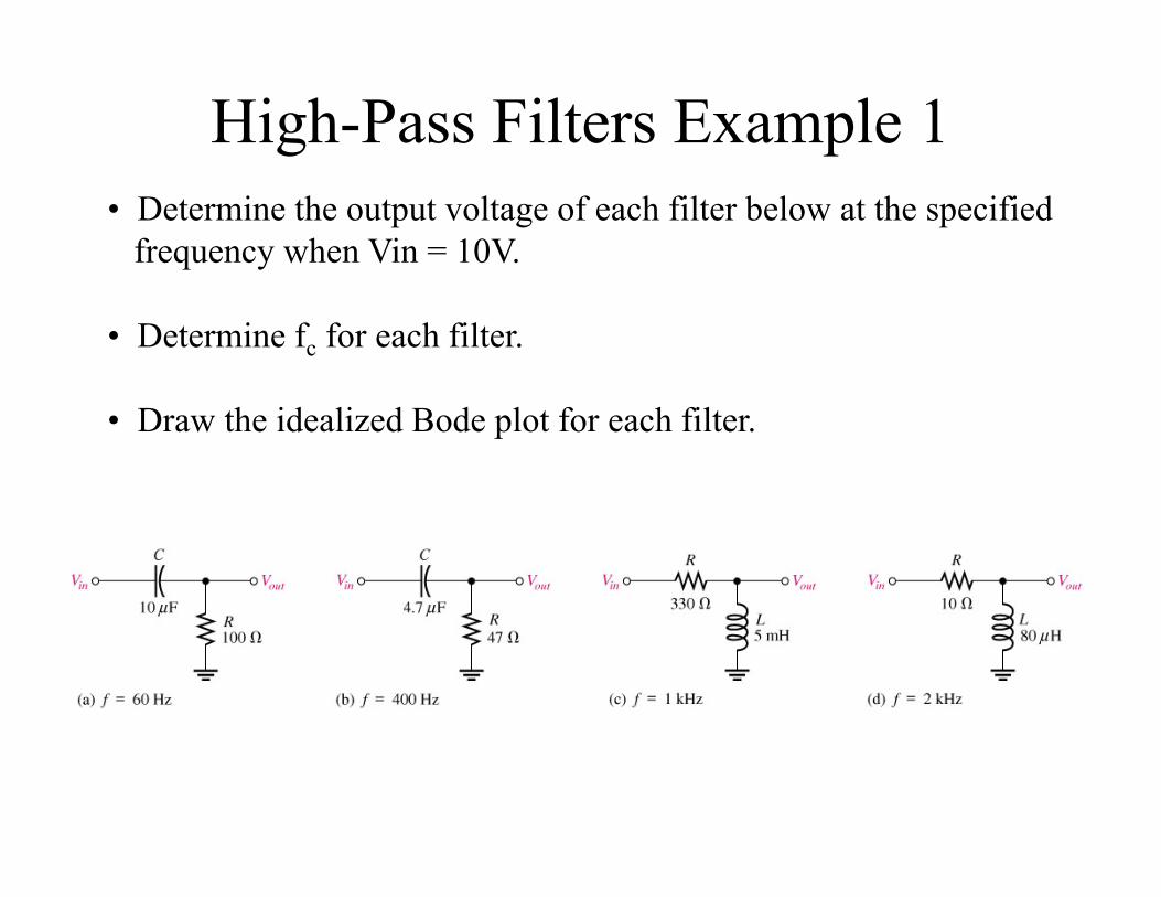
High-Pass Filters Example 1• Determine the output voltage of each filter below at the specified
frequency when Vin = 10V.
• Determine fc for each filter.
• Draw the idealized Bode plot for each filter.
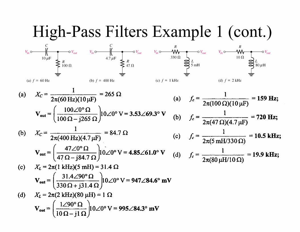
High-Pass Filters Example 1 (cont.)
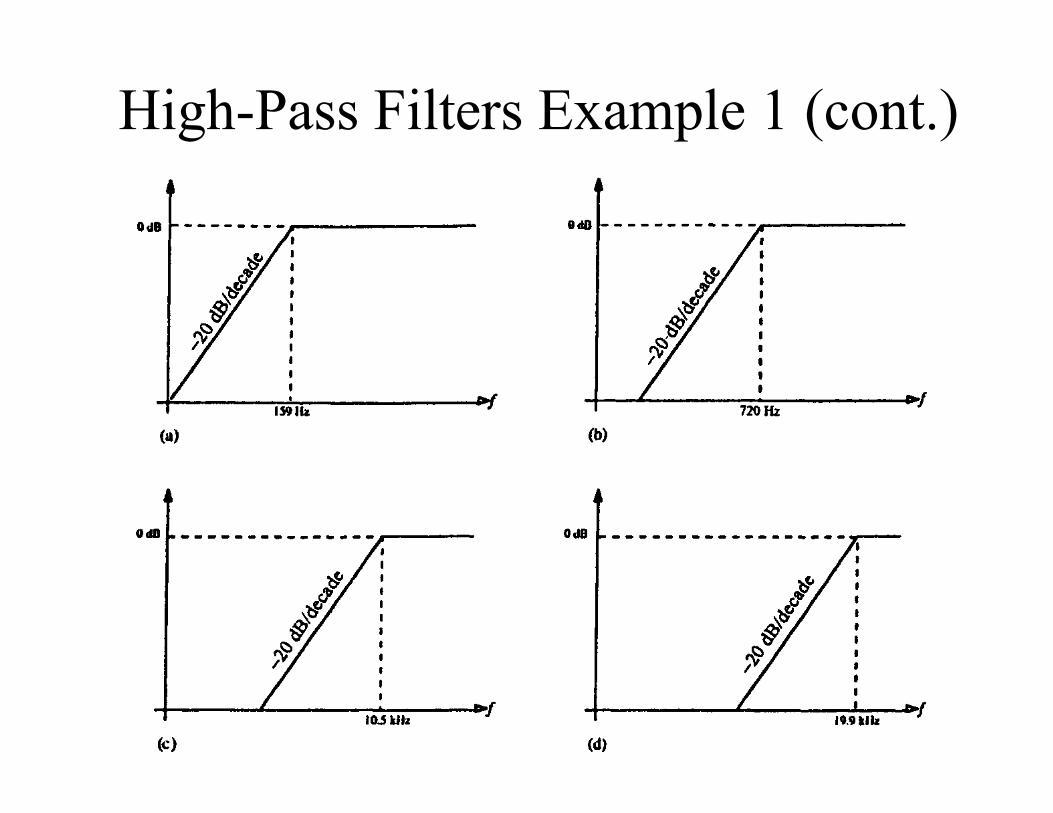
High-Pass Filters Example 1 (cont.)
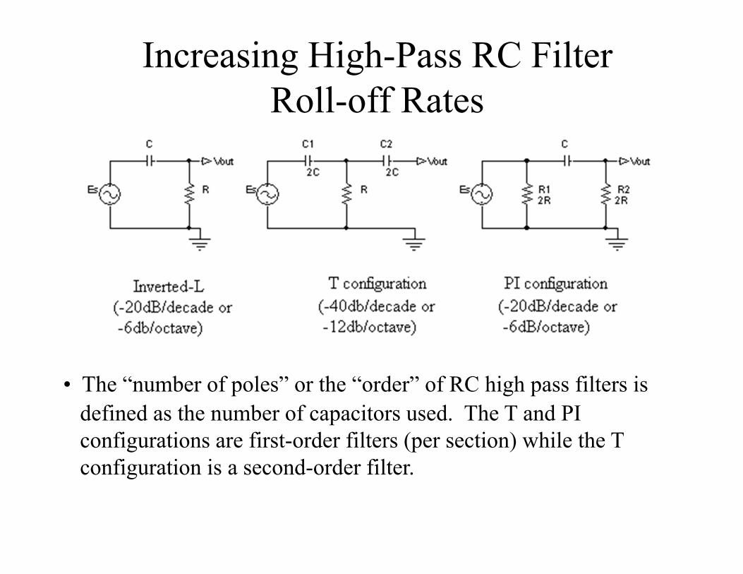
Increasing High-Pass RC Filter Roll-off Rates
• The “number of poles” or the “order” of RC high pass filters is defined as the number of capacitors used. The T and PI configurations are first-order filters (per section) while the T configuration is a second-order filter.
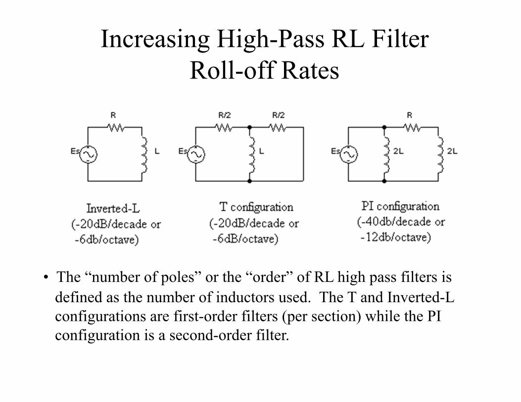
Increasing High-Pass RL Filter Roll-off Rates
• The “number of poles” or the “order” of RL high pass filters is defined as the number of inductors used. The T and Inverted-L configurations are first-order filters (per section) while the PI configuration is a second-order filter.
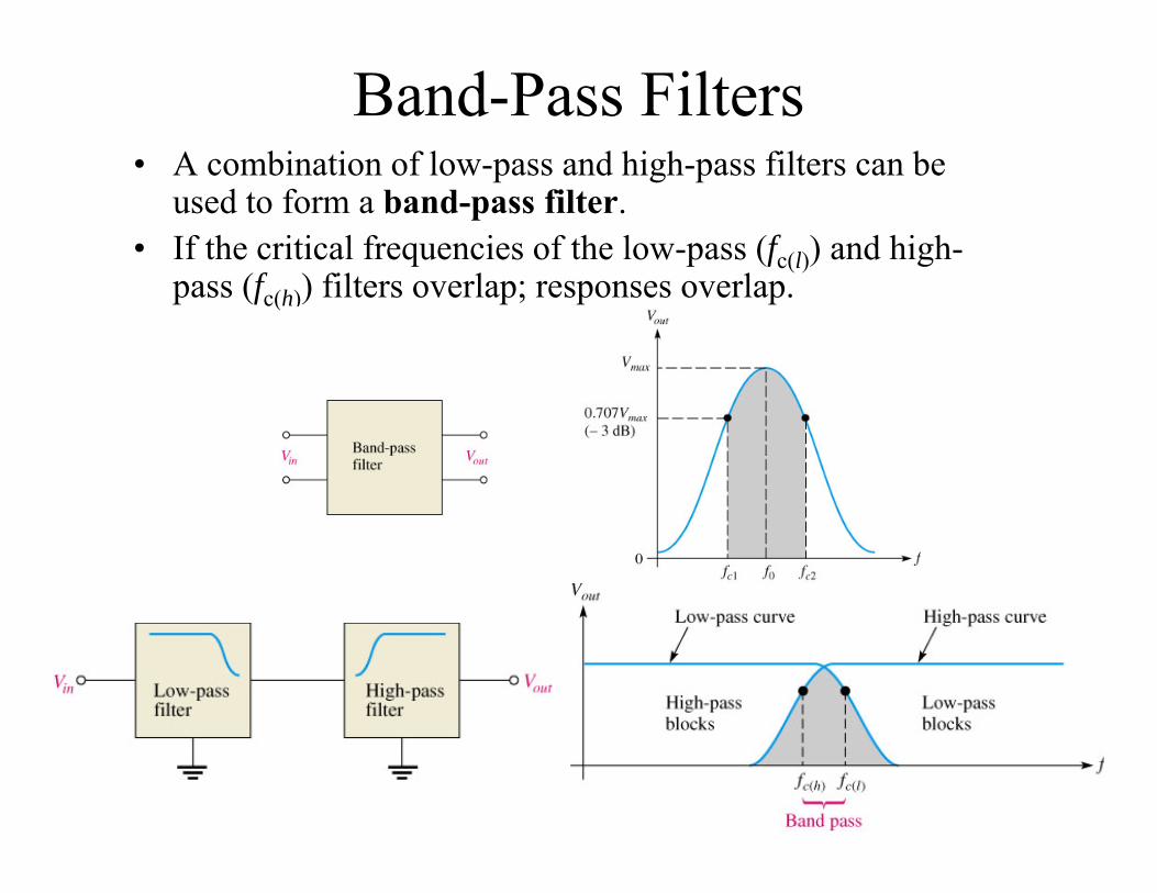
Band-Pass Filters• A combination of low-pass and high-pass filters can be
used to form a band-pass filter.• If the critical frequencies of the low-pass (fc(l)) and high-
pass (fc(h)) filters overlap; responses overlap.
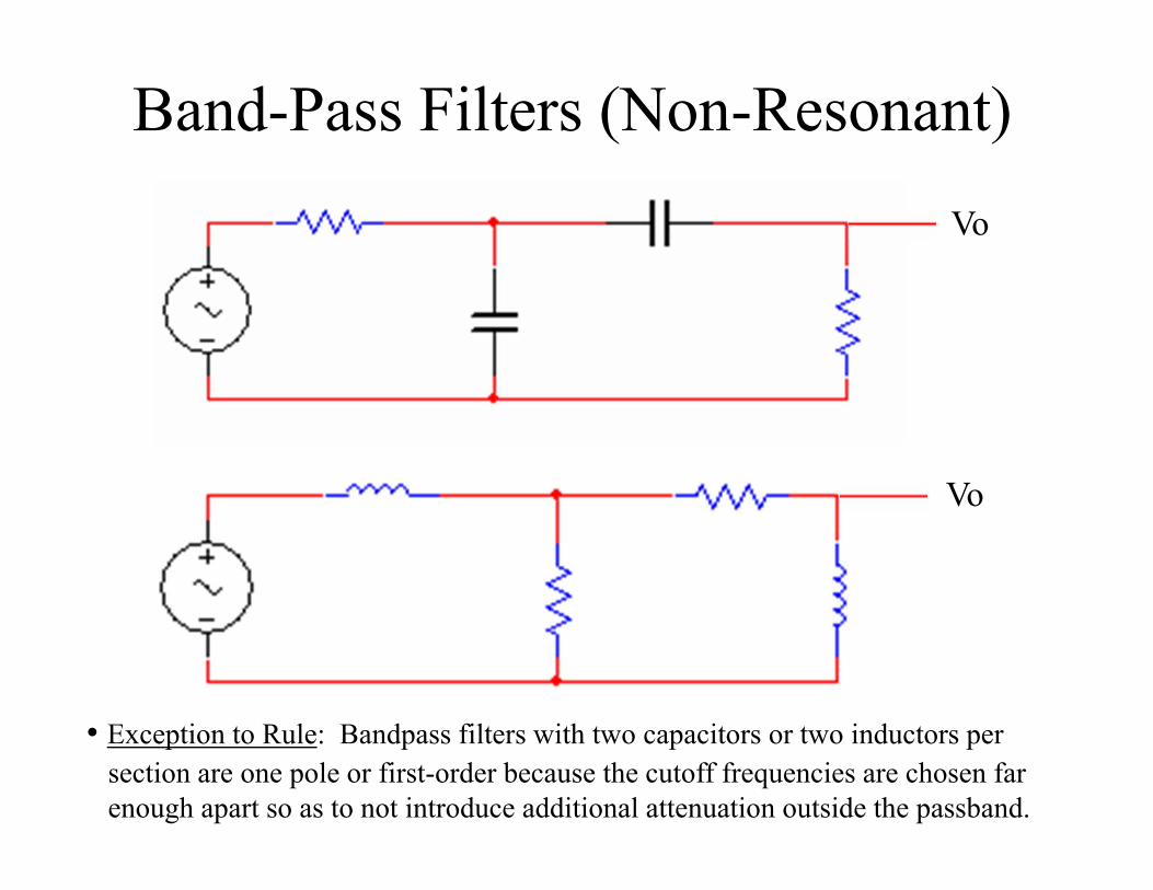
Band-Pass Filters (Non-Resonant)Vo
Vo
• Exception to Rule: Bandpass filters with two capacitors or two inductors per section are one pole or first-order because the cutoff frequencies are chosen far enough apart so as to not introduce additional attenuation outside the passband.
Band-Pass Filter Bandwidth (Non-Resonant)• Non-resonant passive filter circuits use fo to designate the
center frequency since fr doesn’t exist.• The bandwidth (BW) of resonant or non-resonant band-
pass filters is the range of frequencies for which the current, and therefore the output voltage, is equal to or greater than 70.7% of its value at the resonant or center frequency, respectively.
• Applies only to non-resonant passive bandpass filters:– Since the cutoff frequencies are chosen far enough apart as to not
introduce additional attenuation outside the passband, the order of the bandpass filter is defined differently from just a high-pass or low-pass filter individually. The order of the bandpass filter is the order of either the high-pass or the low-pass section per filter section.
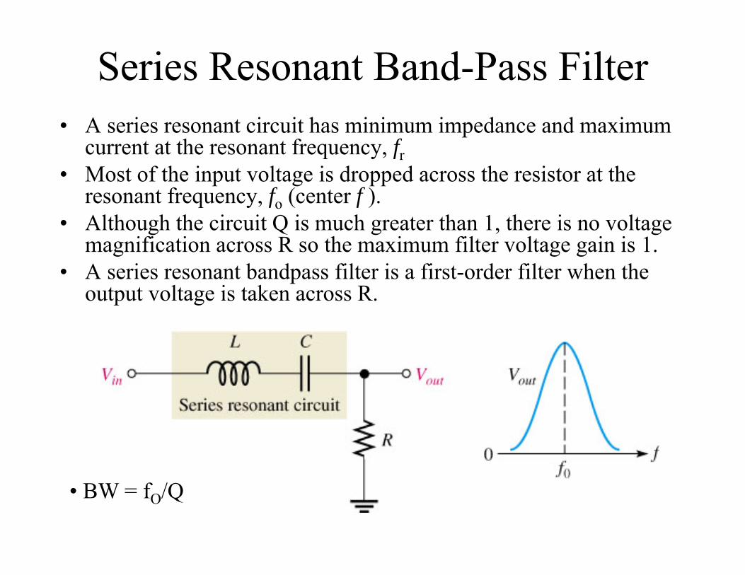
Series Resonant Band-Pass Filter• A series resonant circuit has minimum impedance and maximum
current at the resonant frequency, fr• Most of the input voltage is dropped across the resistor at the
resonant frequency, fo (center f ).• Although the circuit Q is much greater than 1, there is no voltage
magnification across R so the maximum filter voltage gain is 1.• A series resonant bandpass filter is a first-order filter when the
output voltage is taken across R.
• BW = fO/Q
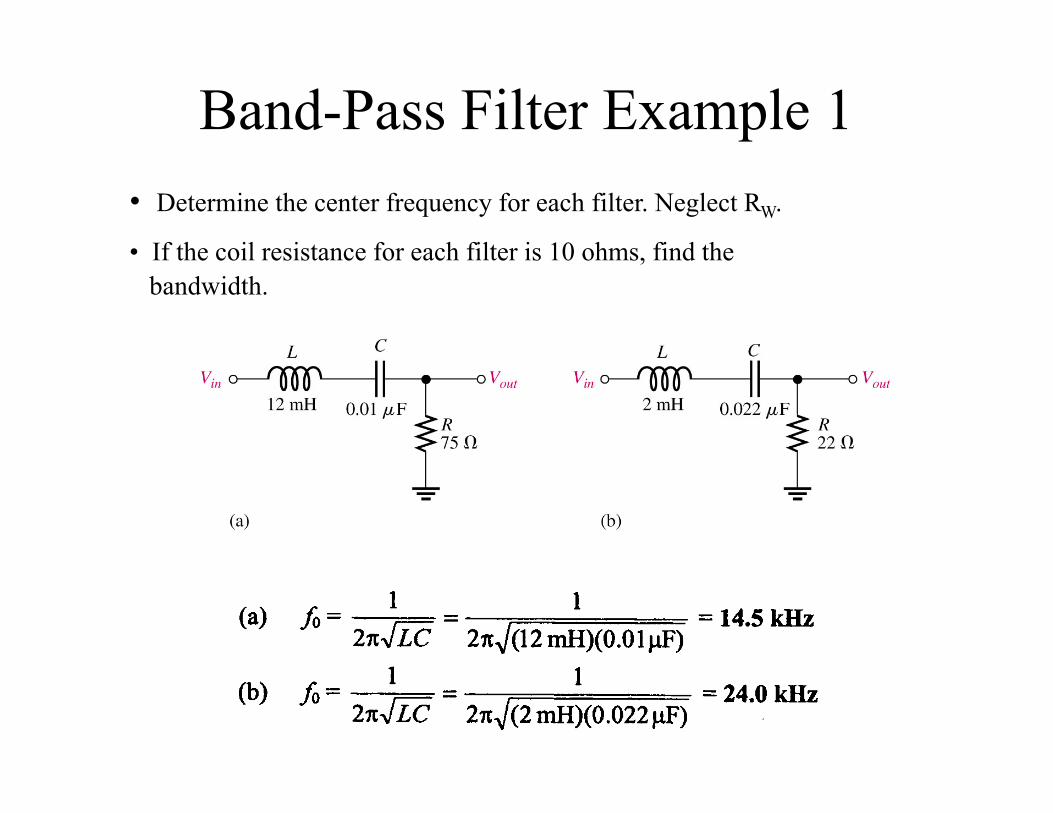
Band-Pass Filter Example 1• Determine the center frequency for each filter. Neglect RW.
• If the coil resistance for each filter is 10 ohms, find the bandwidth.
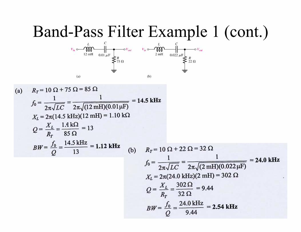
Band-Pass Filter Example 1 (cont.)
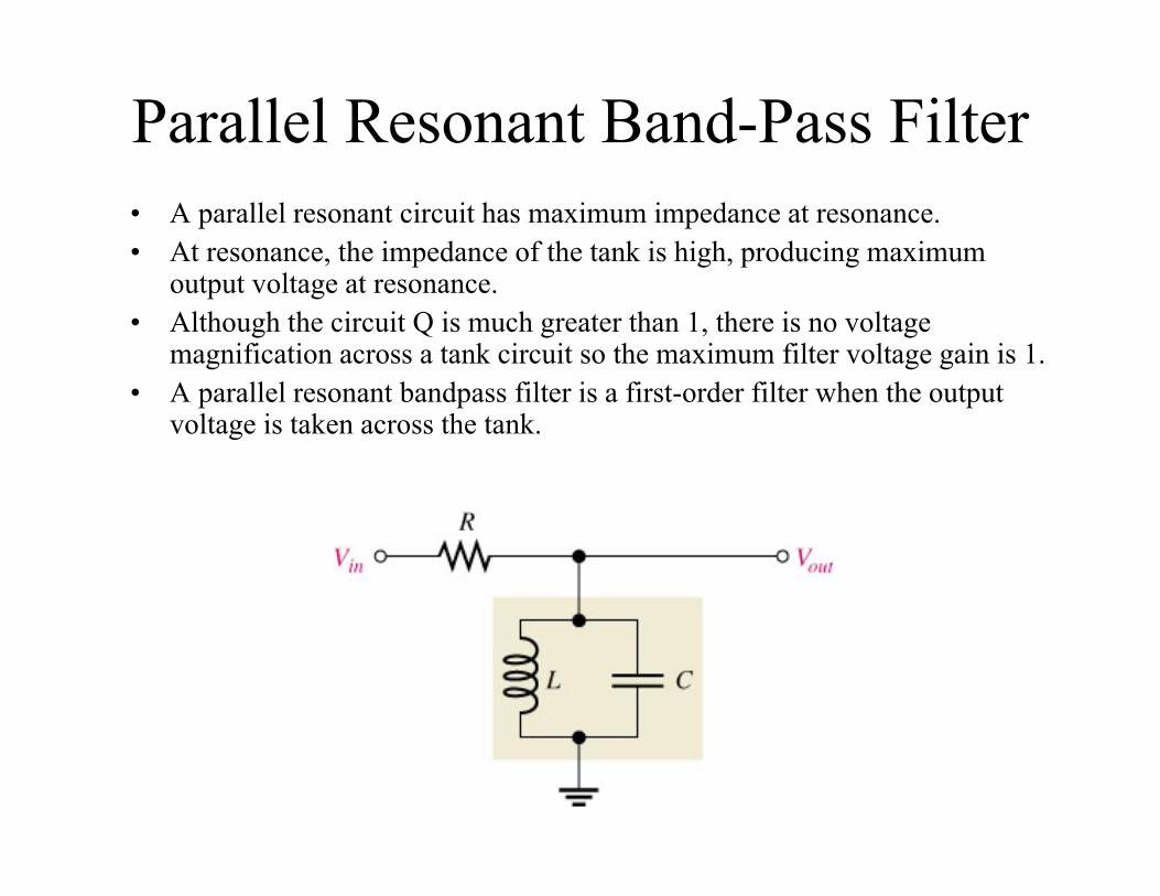
Parallel Resonant Band-Pass Filter• A parallel resonant circuit has maximum impedance at resonance.• At resonance, the impedance of the tank is high, producing maximum
output voltage at resonance.• Although the circuit Q is much greater than 1, there is no voltage
magnification across a tank circuit so the maximum filter voltage gain is 1.• A parallel resonant bandpass filter is a first-order filter when the output
voltage is taken across the tank.
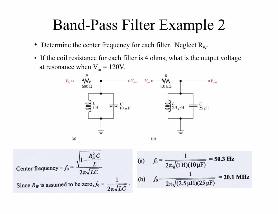
Band-Pass Filter Example 2• Determine the center frequency for each filter. Neglect RW.
• If the coil resistance for each filter is 4 ohms, what is the output voltage at resonance when Vin = 120V.
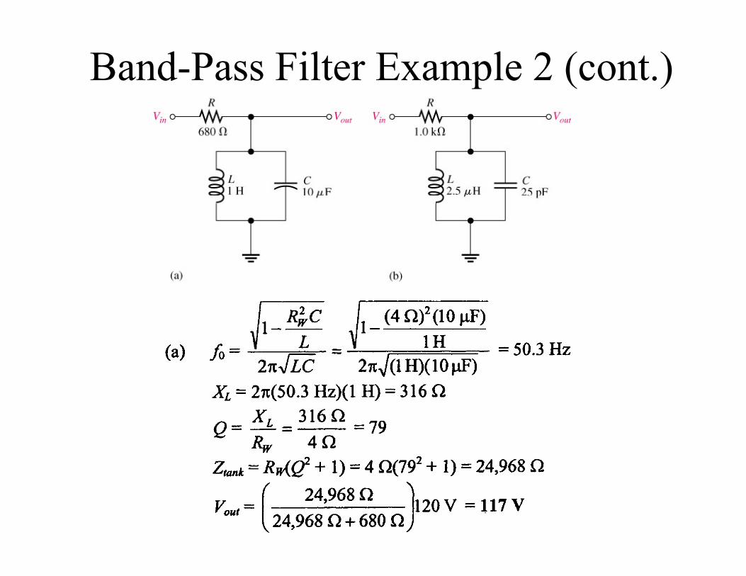
Band-Pass Filter Example 2 (cont.)
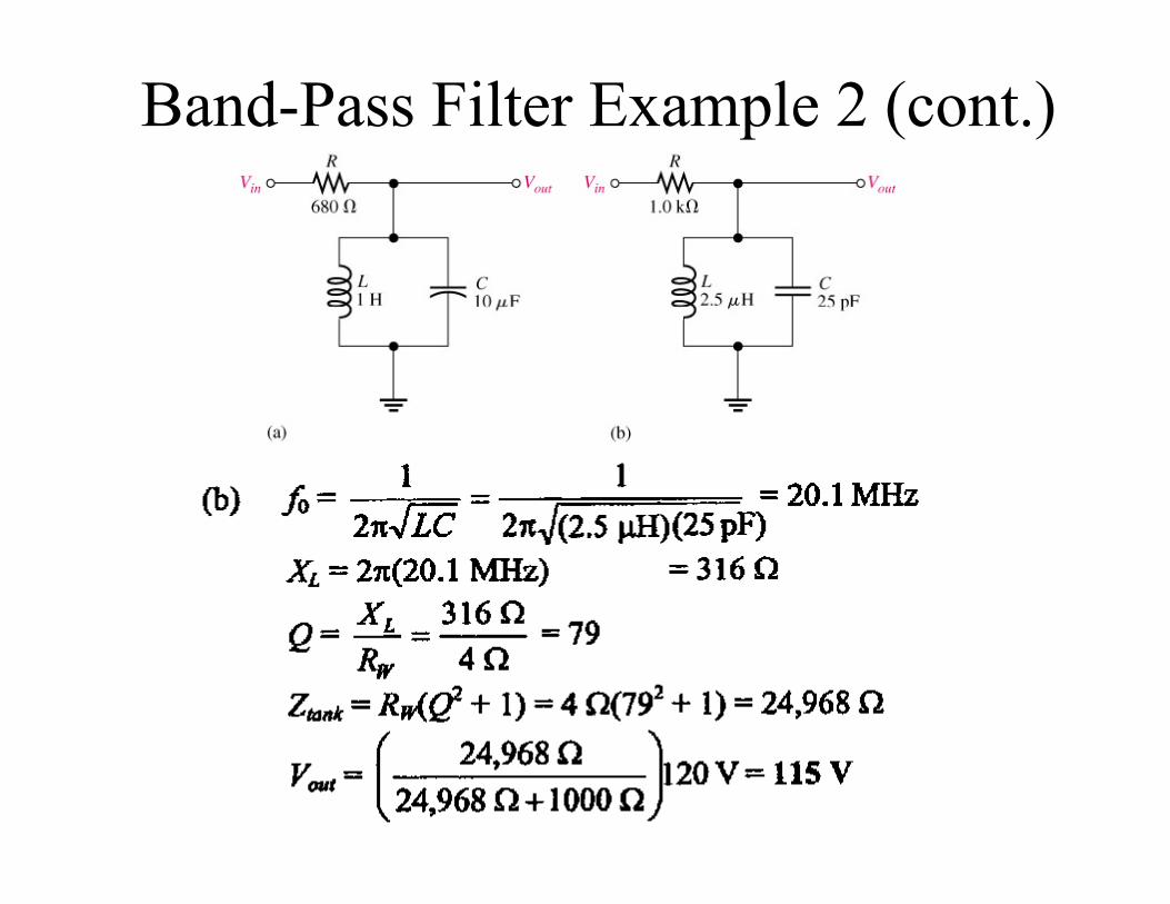
Band-Pass Filter Example 2 (cont.)
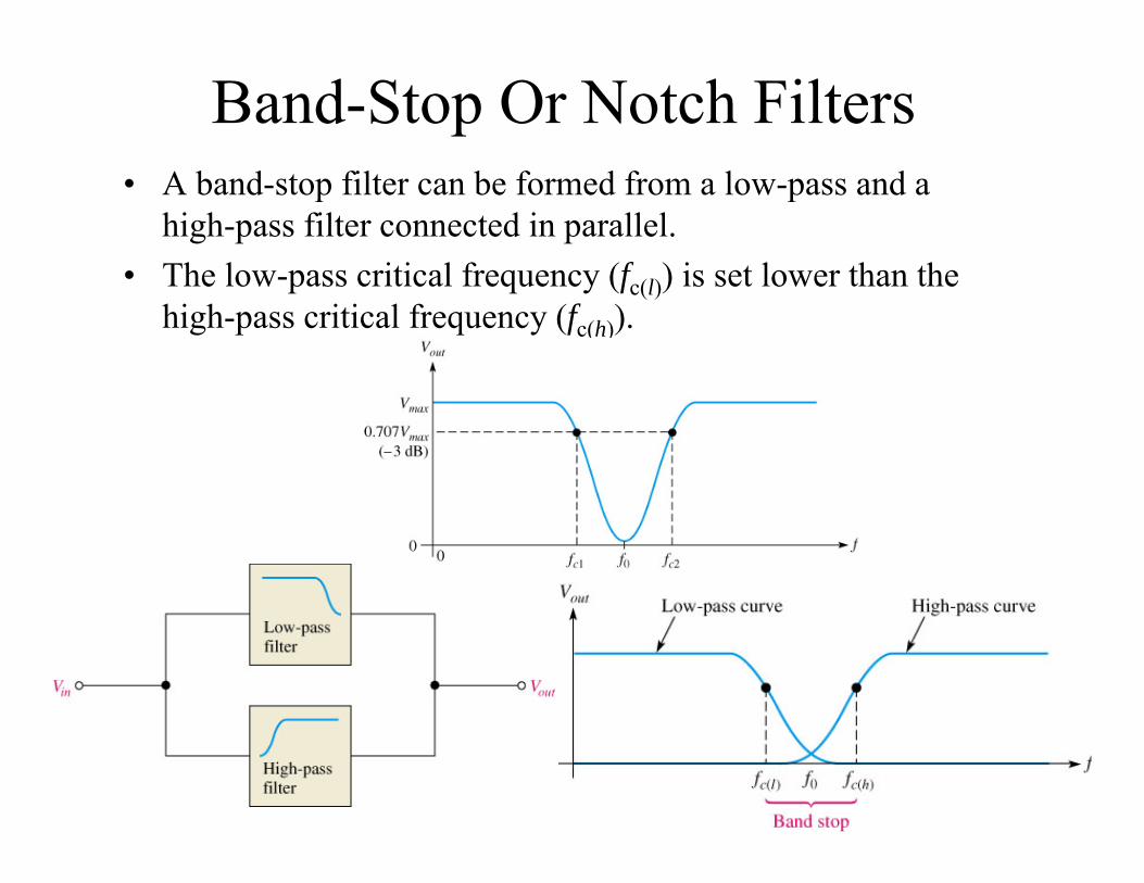
Band-Stop Or Notch Filters• A band-stop filter can be formed from a low-pass and a
high-pass filter connected in parallel.• The low-pass critical frequency (fc(l)) is set lower than the
high-pass critical frequency (fc(h)).
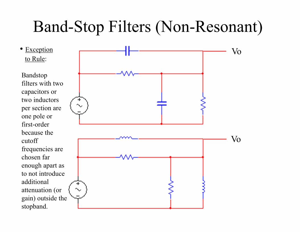
Band-Stop Filters (Non-Resonant)Vo
Vo
• Exception to Rule:
Bandstopfilters with twocapacitors ortwo inductorsper section are one pole or first-order because the cutoff frequencies are chosen far enough apart as to not introduce additional attenuation (or gain) outside the stopband.
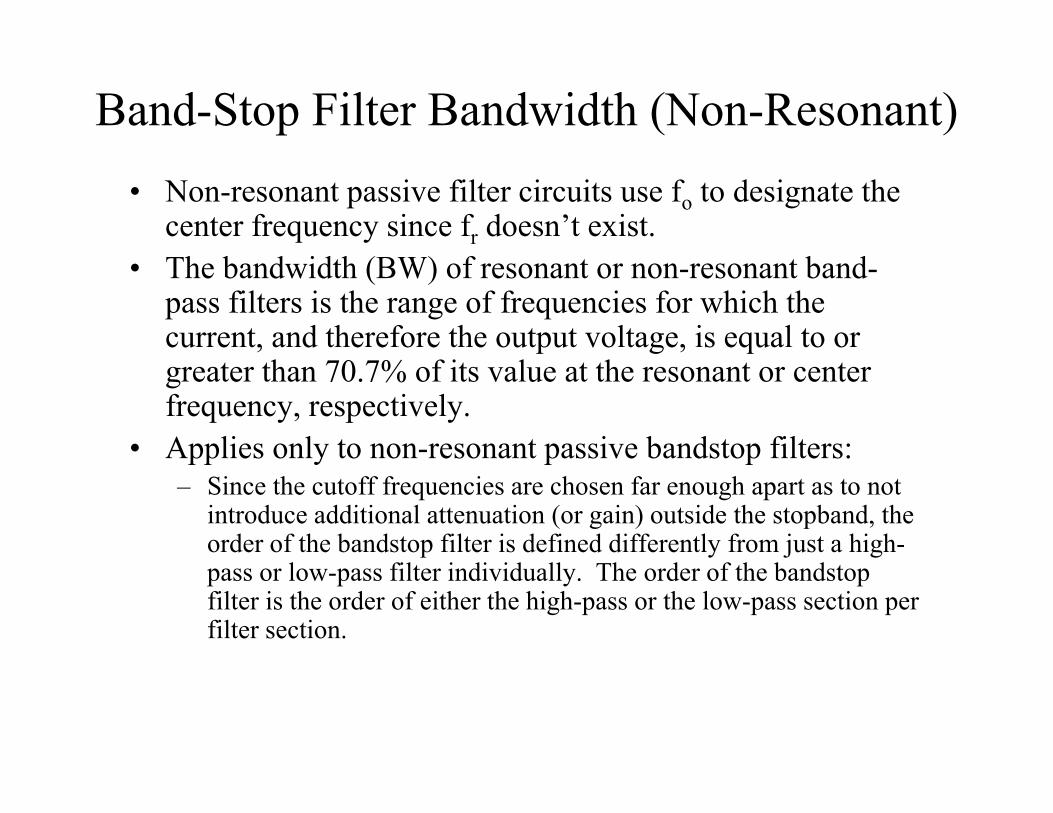
Band-Stop Filter Bandwidth (Non-Resonant)• Non-resonant passive filter circuits use fo to designate the
center frequency since fr doesn’t exist.• The bandwidth (BW) of resonant or non-resonant band-
pass filters is the range of frequencies for which the current, and therefore the output voltage, is equal to or greater than 70.7% of its value at the resonant or center frequency, respectively.
• Applies only to non-resonant passive bandstop filters:– Since the cutoff frequencies are chosen far enough apart as to not
introduce additional attenuation (or gain) outside the stopband, the order of the bandstop filter is defined differently from just a high-pass or low-pass filter individually. The order of the bandstop filter is the order of either the high-pass or the low-pass section per filter section.
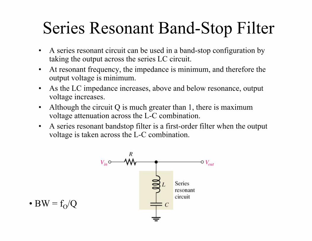
Series Resonant Band-Stop Filter• A series resonant circuit can be used in a band-stop configuration by
taking the output across the series LC circuit.• At resonant frequency, the impedance is minimum, and therefore the
output voltage is minimum.• As the LC impedance increases, above and below resonance, output
voltage increases.• Although the circuit Q is much greater than 1, there is maximum
voltage attenuation across the L-C combination. • A series resonant bandstop filter is a first-order filter when the output
voltage is taken across the L-C combination.
• BW = fO/Q
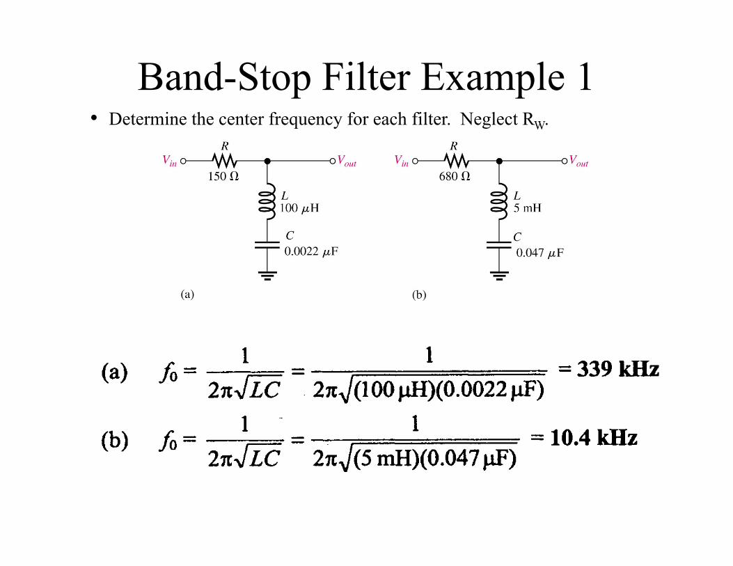
Band-Stop Filter Example 1• Determine the center frequency for each filter. Neglect RW.
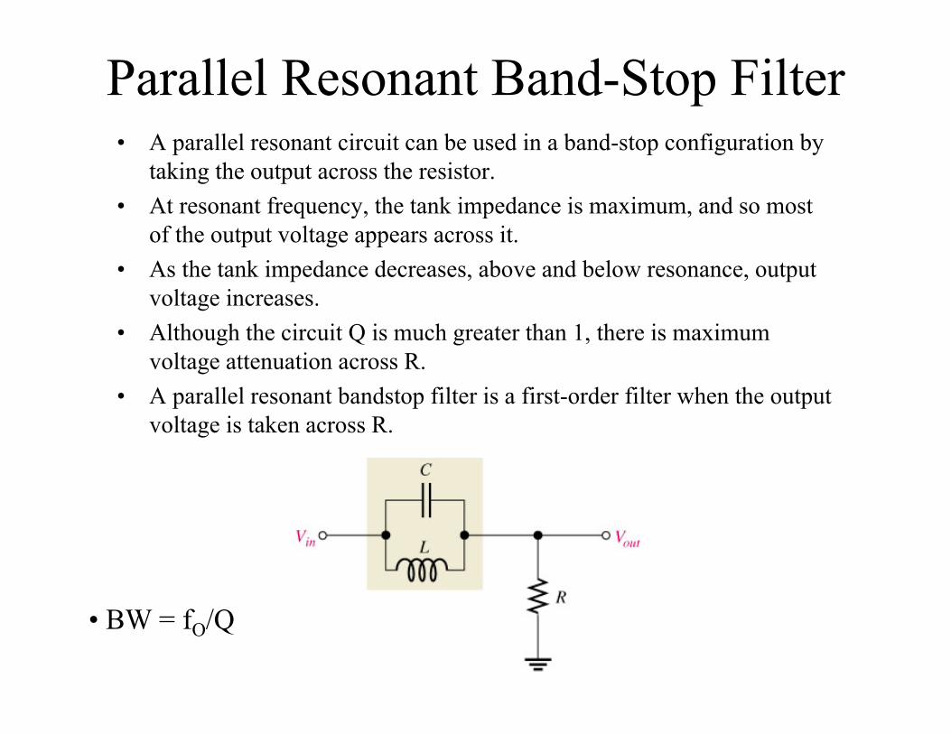
Parallel Resonant Band-Stop Filter• A parallel resonant circuit can be used in a band-stop configuration by
taking the output across the resistor.• At resonant frequency, the tank impedance is maximum, and so most
of the output voltage appears across it.• As the tank impedance decreases, above and below resonance, output
voltage increases.• Although the circuit Q is much greater than 1, there is maximum
voltage attenuation across R. • A parallel resonant bandstop filter is a first-order filter when the output
voltage is taken across R.
• BW = fO/Q
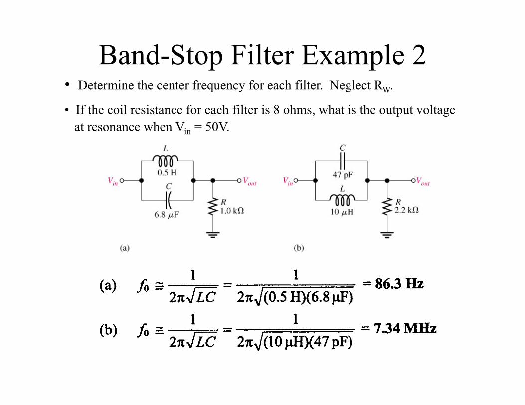
Band-Stop Filter Example 2• Determine the center frequency for each filter. Neglect RW.
• If the coil resistance for each filter is 8 ohms, what is the output voltage at resonance when Vin = 50V.
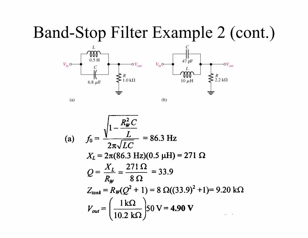
Band-Stop Filter Example 2 (cont.)
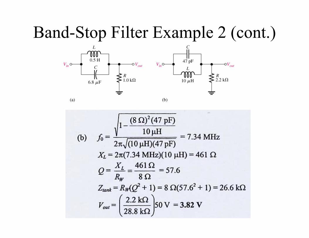
Band-Stop Filter Example 2 (cont.)
Filters Application: Speaker Crossover Networks
You should remember: 1. A passive crossover requires no external power source to operate. 2. A passive crossover uses caps, coils and resistors to attenuate the
signal level above and/or below a certain frequency. 3. Passive crossover networks are designed to pass selected frequencies
to speaker drivers that acoustically reproduce those selected frequencies the most efficiently and accurately.
- Speaker systems are designed as one-way, two-way, three-way, and four-way systems. The “way” means how many speaker drivers are connected together (usually in parallel) per channel output.
- For example, a three-way speaker system contains a woofer driver, a midrange driver, and a tweeter driver. The woofer reproduces the low frequencies the best, the midrange the middle frequencies the best, and the tweeter the high frequencies the best for a given frequency range. It is the crossover network’s job to make sure each speaker driver receives the range of frequencies it can most accurately and efficiently reproduce acoustically.
Filters Application: Speaker Crossover Networks
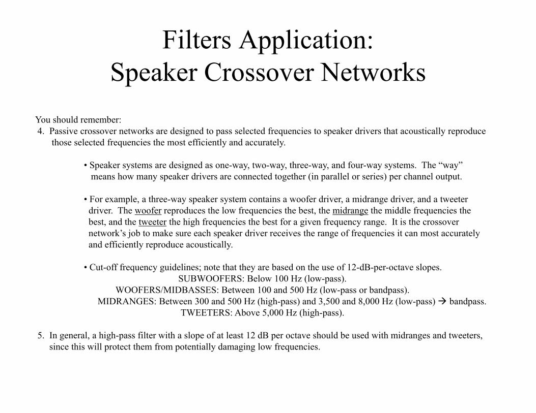
You should remember: 4. Passive crossover networks are designed to pass selected frequencies to speaker drivers that acoustically reproduce
those selected frequencies the most efficiently and accurately.
• Speaker systems are designed as one-way, two-way, three-way, and four-way systems. The “way” means how many speaker drivers are connected together (in parallel or series) per channel output.
• For example, a three-way speaker system contains a woofer driver, a midrange driver, and a tweeter driver. The woofer reproduces the low frequencies the best, the midrange the middle frequencies the best, and the tweeter the high frequencies the best for a given frequency range. It is the crossover network’s job to make sure each speaker driver receives the range of frequencies it can most accurately and efficiently reproduce acoustically.
• Cut-off frequency guidelines; note that they are based on the use of 12-dB-per-octave slopes. SUBWOOFERS: Below 100 Hz (low-pass).
WOOFERS/MIDBASSES: Between 100 and 500 Hz (low-pass or bandpass). MIDRANGES: Between 300 and 500 Hz (high-pass) and 3,500 and 8,000 Hz (low-pass) bandpass.
TWEETERS: Above 5,000 Hz (high-pass).
5. In general, a high-pass filter with a slope of at least 12 dB per octave should be used with midranges and tweeters, since this will protect them from potentially damaging low frequencies.
Filters Application: Speaker Crossover Networks
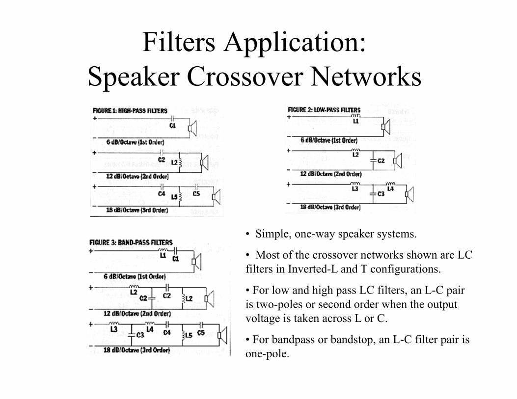
• Simple, one-way speaker systems.
• Most of the crossover networks shown are LC filters in Inverted-L and T configurations.
• For low and high pass LC filters, an L-C pair is two-poles or second order when the output voltage is taken across L or C.
• For bandpass or bandstop, an L-C filter pair is one-pole.
Filters Application: Speaker Crossover Networks
Filters Application: Speaker Crossover Networks
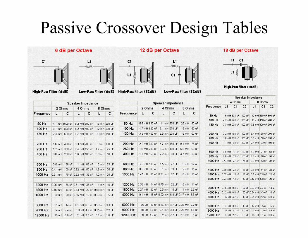
Passive Crossover Design Tables
Filters Application: Speaker Crossover Networks
• Passive High Pass Crossovers
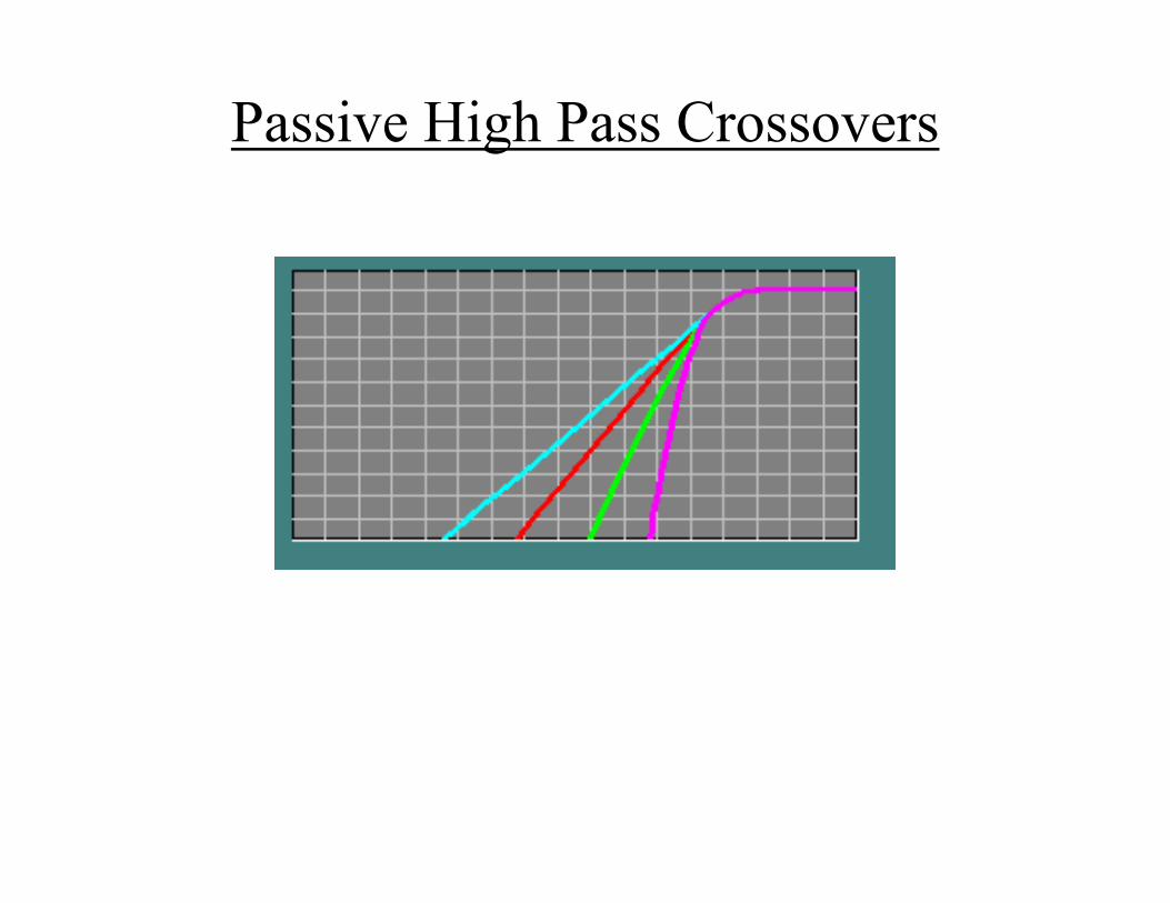
• In the next four slides, there are 4 different crossover configurations. The graph shown after the 4 systems shows the slopes for -6dB (first order), -12dB (second order), -18dB (third order) and -24dB (fourth order) per octave crossovers. The crossover components' colors match its corresponding curve on the graph.
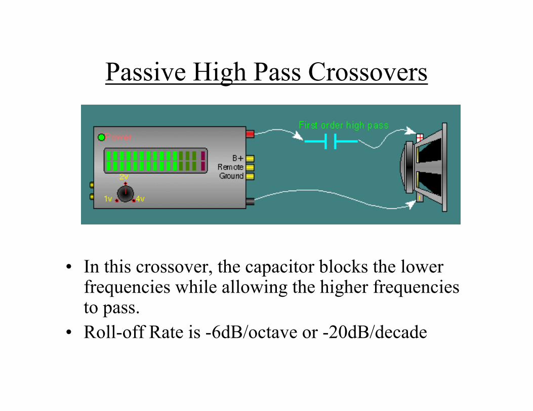
Passive High Pass Crossovers
• In this crossover, the capacitor blocks the lower frequencies while allowing the higher frequencies to pass.
• Roll-off Rate is -6dB/octave or -20dB/decade
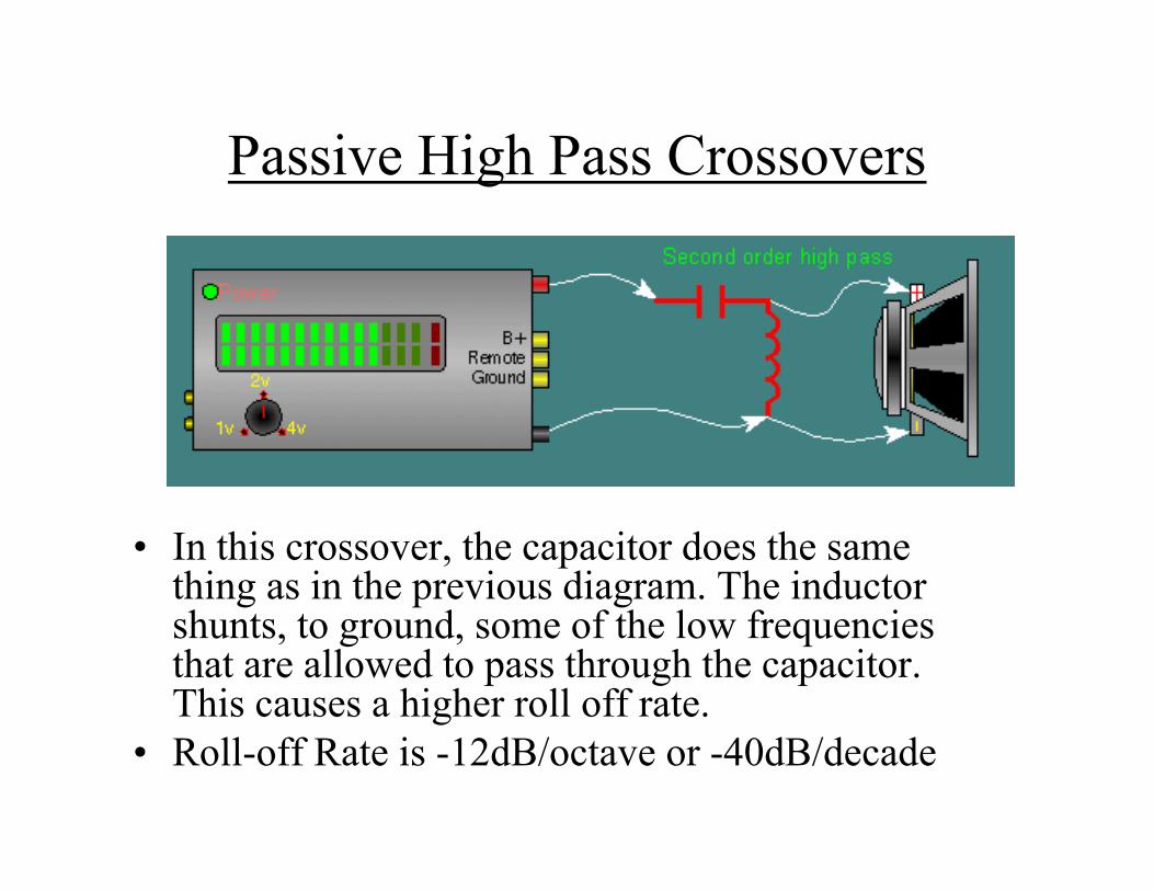
Passive High Pass Crossovers
• In this crossover, the capacitor does the same thing as in the previous diagram. The inductor shunts, to ground, some of the low frequencies that are allowed to pass through the capacitor. This causes a higher roll off rate.
• Roll-off Rate is -12dB/octave or -40dB/decade
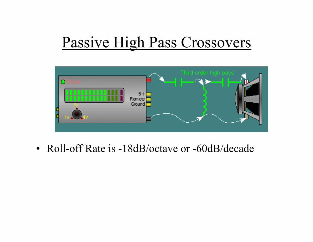
Passive High Pass Crossovers
• Roll-off Rate is -18dB/octave or -60dB/decade
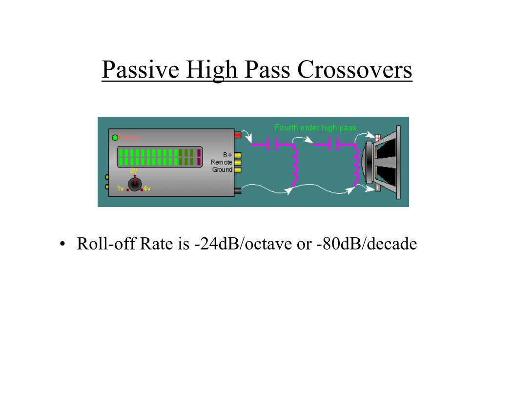
Passive High Pass Crossovers
• Roll-off Rate is -24dB/octave or -80dB/decade
Passive High Pass Crossovers
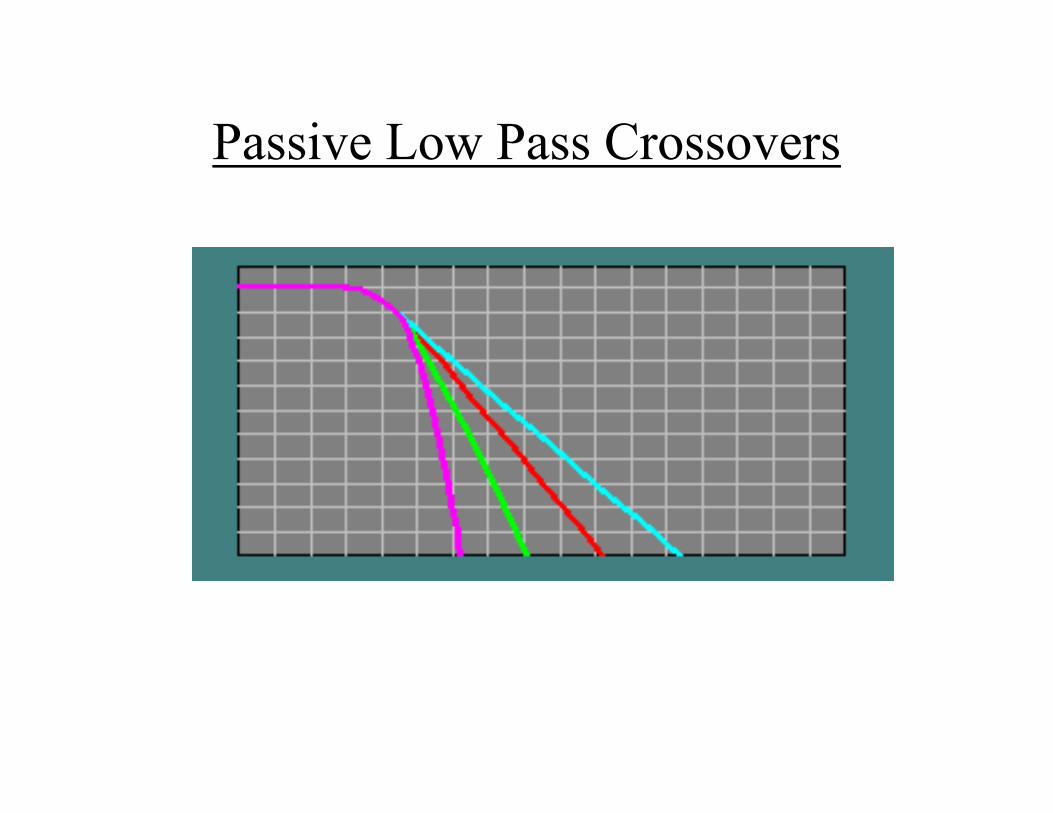
Passive Low Pass Crossovers
• In the next four slides, there are 4 different crossover configurations. The graph shown after the 4 systems shows the slopes for -6dB (first order), -12dB (second order), -18dB (third order) and -24dB (fourth order) per octave crossovers. The crossover components' colors match its corresponding curve on the graph.
Passive Low Pass Crossovers
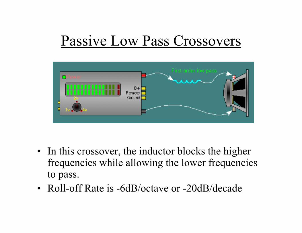
• In this crossover, the inductor blocks the higher frequencies while allowing the lower frequencies to pass.
• Roll-off Rate is -6dB/octave or -20dB/decade
Passive Low Pass Crossovers
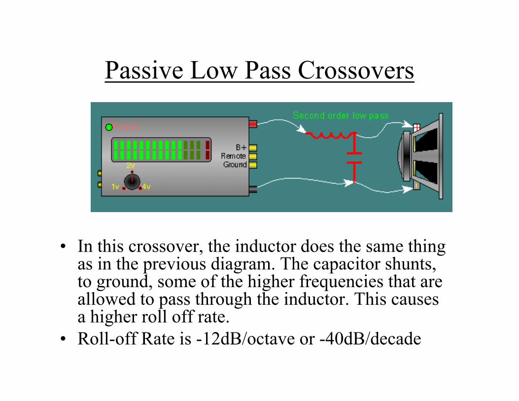
• In this crossover, the inductor does the same thing as in the previous diagram. The capacitor shunts, to ground, some of the higher frequencies that are allowed to pass through the inductor. This causes a higher roll off rate.
• Roll-off Rate is -12dB/octave or -40dB/decade
Passive Low Pass Crossovers
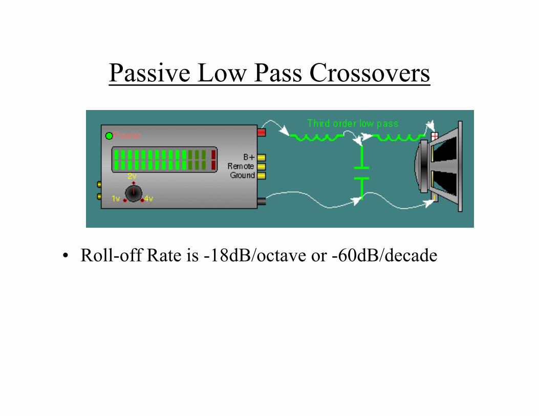
• Roll-off Rate is -18dB/octave or -60dB/decade
Passive Low Pass Crossovers
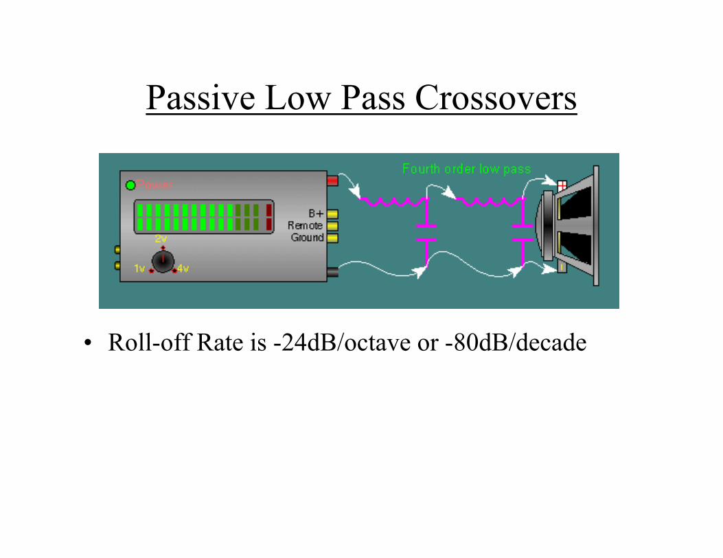
• Roll-off Rate is -24dB/octave or -80dB/decade
Passive Low Pass Crossovers
Other Types of Crossover Networks• Basics:
– When you double the cone area (add a second speaker with equal properties) while keeping the power constant, you gain 3dB of output. If you reduce the number of speakers by 1/2, you lose 3dB.
– If you double the power to a driver, you gain 3dB. If you cut the power by 1/2 you lose 3dB.
– If you double the cone area and the power (by paralleling the second speaker on the amplifier), you gain 6dB.
– The 'Q' of a filter (crossover) indicates the shape of the curve. For a second order crossover, it can be calculated with the formula: Q=[(R2C)/L]1/2
Where R is the speaker's impedance. C is the capacitor used in the filter. And L is the inductor used in the filter.
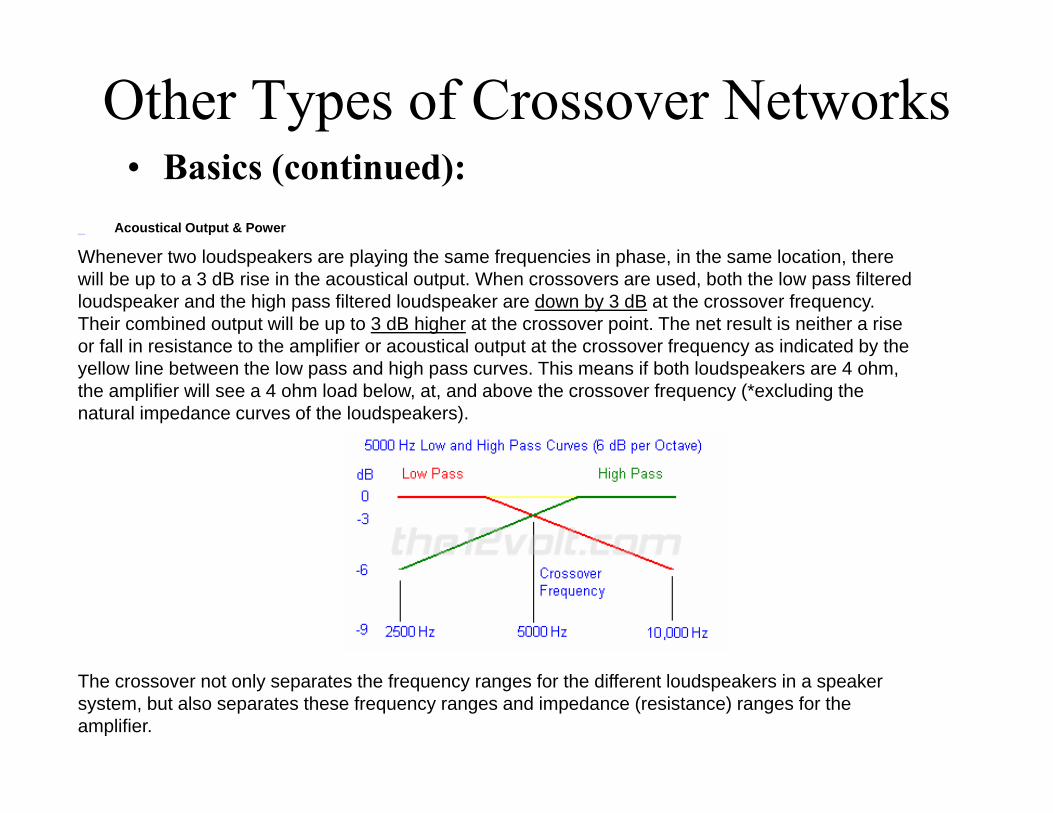
Other Types of Crossover Networks• Basics (continued):
Acoustical Output & Power
Whenever two loudspeakers are playing the same frequencies in phase, in the same location, there will be up to a 3 dB rise in the acoustical output. When crossovers are used, both the low pass filtered loudspeaker and the high pass filtered loudspeaker are down by 3 dB at the crossover frequency. Their combined output will be up to 3 dB higher at the crossover point. The net result is neither a rise or fall in resistance to the amplifier or acoustical output at the crossover frequency as indicated by the yellow line between the low pass and high pass curves. This means if both loudspeakers are 4 ohm, the amplifier will see a 4 ohm load below, at, and above the crossover frequency (*excluding the natural impedance curves of the loudspeakers).
The crossover not only separates the frequency ranges for the different loudspeakers in a speaker system, but also separates these frequency ranges and impedance (resistance) ranges for the amplifier.
2nd order Linkwitz-Riley• In the following graph, you can see the response
for both the high and low frequency drivers. You can also see that the crossover point is 150hz. As previously noted, the on-axis acoustic output of a L-R crossover has a flat response at the crossover frequency. To do this, the crossover point has to be 6 dB down (2nd-order). Since there are 2 drivers (a midrange and a woofer) operating at the crossover point and they presumably have a comparable output and they are receiving the same power (both 6dB down from full power), the output (their summed on-axis acoustic output) will be as if a single driver were playing at the crossover point. This will provide a flat overall frequency response at the crossover point.

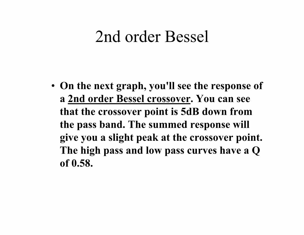
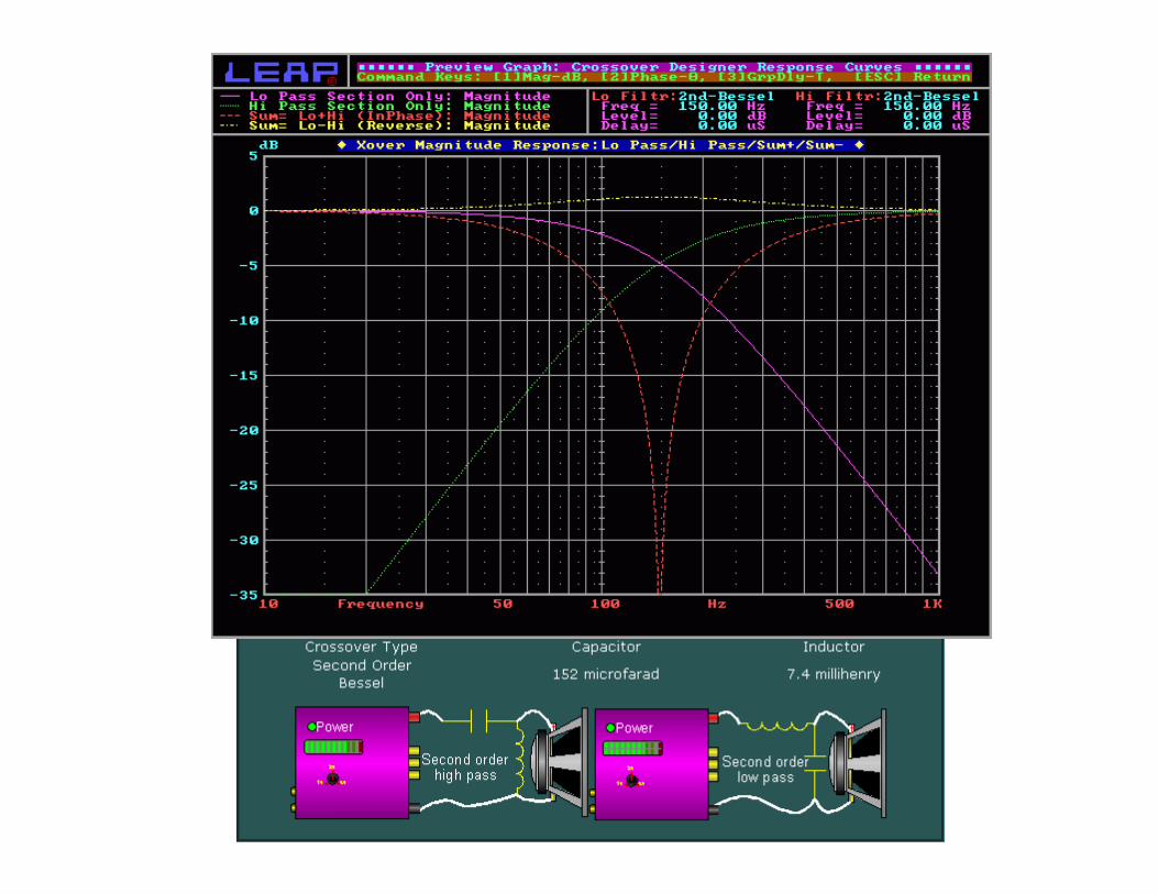
2nd order Bessel
• On the next graph, you'll see the response of a 2nd order Bessel crossover. You can see that the crossover point is 5dB down from the pass band. The summed response will give you a slight peak at the crossover point. The high pass and low pass curves have a Q of 0.58.
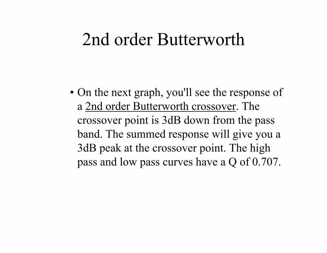
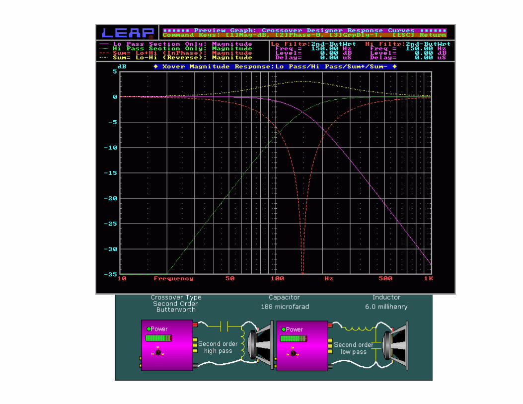
2nd order Butterworth
• On the next graph, you'll see the response of a 2nd order Butterworth crossover. The crossover point is 3dB down from the pass band. The summed response will give you a 3dB peak at the crossover point. The high pass and low pass curves have a Q of 0.707.
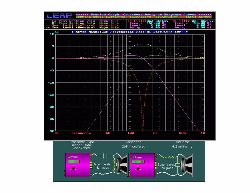
2nd order Chebychev
• On the next graph, you'll see the response of a 2nd order Chebychev crossover. The crossover point is at the same level as the pass band. The summed response will give you a 6dB peak at the crossover point. The high pass and low pass curves have a Q of 1.0.
Open Crossover Output Warning
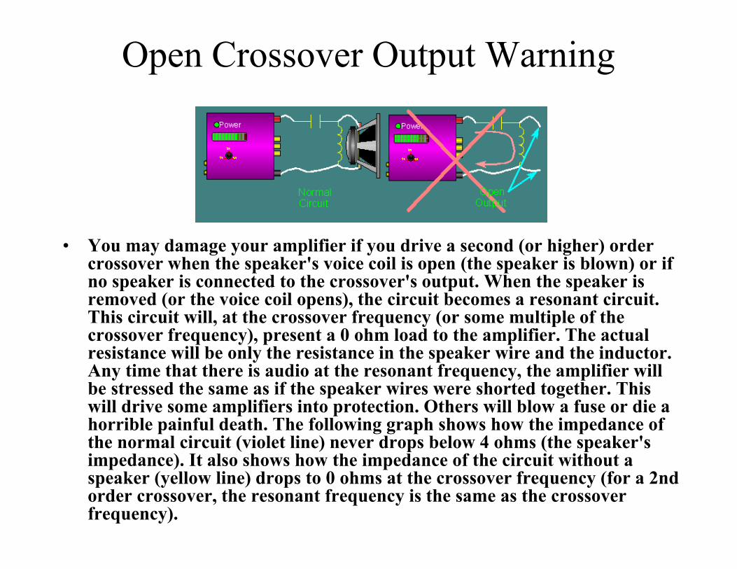
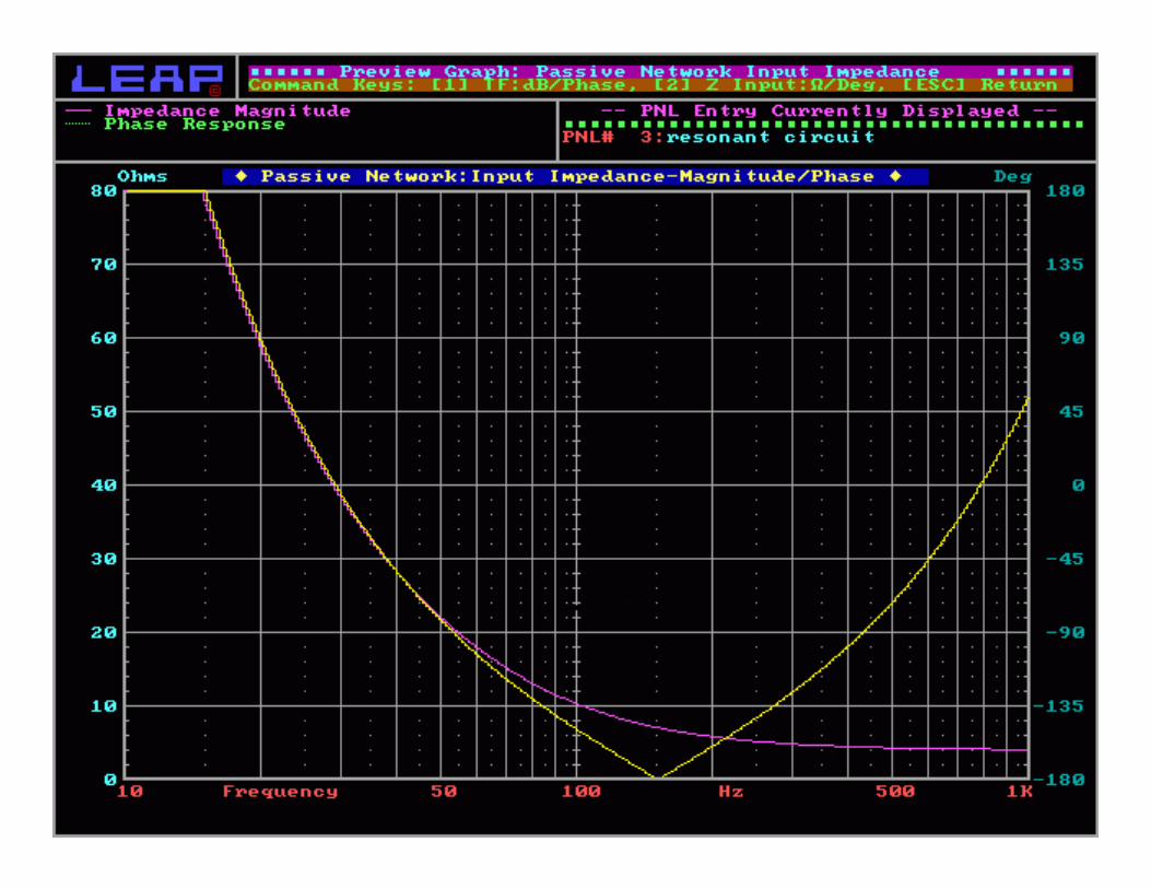
• You may damage your amplifier if you drive a second (or higher) order crossover when the speaker's voice coil is open (the speaker is blown) or if no speaker is connected to the crossover's output. When the speaker is removed (or the voice coil opens), the circuit becomes a resonant circuit. This circuit will, at the crossover frequency (or some multiple of the crossover frequency), present a 0 ohm load to the amplifier. The actual resistance will be only the resistance in the speaker wire and the inductor. Any time that there is audio at the resonant frequency, the amplifier will be stressed the same as if the speaker wires were shorted together. This will drive some amplifiers into protection. Others will blow a fuse or die a horrible painful death. The following graph shows how the impedance of the normal circuit (violet line) never drops below 4 ohms (the speaker's impedance). It also shows how the impedance of the circuit without a speaker (yellow line) drops to 0 ohms at the crossover frequency (for a 2nd order crossover, the resonant frequency is the same as the crossover frequency).
Summary
• In an RC low-pass filter, the output voltage is taken across the capacitor and the output lags the input.
• In an RL low-pass filter, the output voltage is taken across the resistor and the output lags the input.
• In an RC high-pass filter, the output is taken across the resistor and the output leads the input.
Summary
• In an RL high-pass filter, the output is taken across the inductor and the output leads the input.
• The roll-off rate of a basic RC or RL filter is -20 dB per decade.
• A band-pass filter passes frequencies between the lower and upper critical frequencies and rejects all others.
Summary
• The bandwidth of a resonant filter is determined by the quality factor (Q) of the circuit and the resonant frequency.
• Critical frequencies are also called -3 dB frequencies.
• The output voltage is 70.7% of its maximum at the critical frequencies.
![€¦ · Web view2009. 4. 23. · [Cr2O72-] Reverse Rate. A. increases increases. B. increases decreases. C. decreases decreases. D. decreases increases. 31. A small amount of H2SO4](https://static.fdocuments.us/doc/165x107/608f2c47b9e3f5096f2e5efc/web-view-2009-4-23-cr2o72-reverse-rate-a-increases-increases-b-increases.jpg)


![APPENDIX D. BINARY-DECIMAL-HEXADECIMAL CONVERSION …faculty.chemeketa.edu/csekafet/ELT253/8085/... · Appendix D. Binary-Decimal·Hexadecimal Conver,jot] Tables . HEXADECIMAL-DECIMAL](https://static.fdocuments.us/doc/165x107/5ea5c10874b2b667df42579d/appendix-d-binary-decimal-hexadecimal-conversion-appendix-d-binary-decimalhexadecimal.jpg)
