CHAPTER – I - Shodhgangashodhganga.inflibnet.ac.in/bitstream/10603/4090/20/07_chapter 1.pdf ·...
44
11 CHAPTER – I General Introduction and Literature Survey
Transcript of CHAPTER – I - Shodhgangashodhganga.inflibnet.ac.in/bitstream/10603/4090/20/07_chapter 1.pdf ·...

11
CHAPTER – I
General Introduction and Literature Survey
12
1.1 General: Need of supercapacitor, nanomaterials for supercapacitors
1.1.1 Need of supercapacitor
Now days, due to use of fossil fuels, environment pollution, global
warming, and rapid resource depletion, the technology advances in modern
society have driven the development of variety of electrochemical power
sources, which offer “clean energy”. The exponential growth in various
portable electronic devices as well as interest in electric vehicle for clean air has
created intense worldwide activity in electrochemical power sources. There are
several power types of electrochemical power systems. These are batteries, fuel
cell and supercapacitors [1]. The electrochemical power systems offer several
advantages compared to fuel combustion systems. First of all, they provide
clean energy and attractive from an environmental point of view. Secondly,
they are potentially more efficient than fuel combustion systems. In the case of
a fuel combustion system, efficiency of conversion is limited by the 2nd law of
thermodynamics (Carnot cycle) and the converted thermal energy needs another
conversion step such as the generation procedure to get electrical energy. They
converted directly the Gibbs free energy of chemical reaction to electrical
energy. Thirdly, the electrochemical systems are appealing in terms of world
energy security and utilizing the available energy resources in a more
economical way [2].
Easy accessible source now present is the electrical energy which is not
available at all time. Consequently, there is need of development of improved
methods for storing electrical energy when it is available and retrieving when it
is needed. Stored electrical energy is required in many house hold as well as
industrial applications e.g. cell phones, pagers, solar cells, computers, satellites,
stand by power supply systems, hybrid electric vehicles, etc [3]. Electrical
energy can be stored in two fundamental ways; (a) Batteries (Indirect way): In
batteries as potentially available chemical energy required faradic oxidation and

13
reduction of the electroactive reagents to release charges that can perform
electrical work when they flow between two electrodes having different
electrode potentials. During the storage of electrochemical energy in a battery,
chemical inter-conversions of electrode material occurs usually with
concomitant phase changes. Although the overall energy changes can be
conducted in a relatively reversible thermodynamic route, the charge and
discharge processes in a storage battery often involve irreversibility in inter-
conversions of the chemical electrode-reagents. Accordingly, the cycle life of
storage batteries is usually limited, and varies with battery type [4]. (b)
Capacitor (Direct way): in capacitors, the electrostatic way as negative and
positive electrical charges on the plates of a capacitor by a process as non-
faradic electrical energy storage. A battery has two different types of active
materials entrapped in a suitable conductive matrix as anodes and cathodes to
sustain the net cell reactions, while a capacitor comprises a dielectric
sandwiched between two identical electrodes. Energy stored by capacitor, only
an excess and a deficiency of electron charges on the capacitor plates have to be
established on charge and reverse on discharge, and no chemical changes
involved. Accordingly, a capacitor has an almost unlimited recyclablity,
typically between 105 to 106 times [3, 5].
At relatively low rates of discharge, say five hours, a battery can totally
discharged and 100 percent of the stored energy can be obtained. However, at
very high rates of discharge, say just a few seconds, only few percent of energy
stored capacity used for the discharge. So, although the battery can perform
duty, and regular does, it requires and electrical an electrical capacity, and
therefore weight and volume, which is much higher than electrical output
required. Lead-acid batteries have additional problem that, when optimized for
higher-rate discharges (as an automotive batteries), their operating life in
industrial applications is very short [6]. Capacitors exist at the opposite end of

14
the scale. They can deliver all their stored energy virtually instantaneously
within few thousands of second. But the amount available is very tiny, just
enough to pop a flash bulb.
Now, with the recent emergence of supercapacitor, there seem to
possibility of an ideal compromise, which combines some storage capabilities
of batteries and some of the power discharge characteristic of capacitors in a
device capable of storing useful quantities of electricity which can discharge
very quickly. To understand exactly why supercapacitor so special it is useful to
consider the classic capacitor. Capacitance is measured in Farads (F) - a 1 F
capacitor charged to 1V can supply 1A of current for 1 Second. Still, highest
value capacitors available do not even approach one Farad and are actually
measured in microfarads, which of course required for most electronic
application. In contrast to ordinary capacitors supercapcitor’s capacitance
measured in whole Farads (F), and now even kiloFarads (kF), which means that
they can store million times the electrical charge.
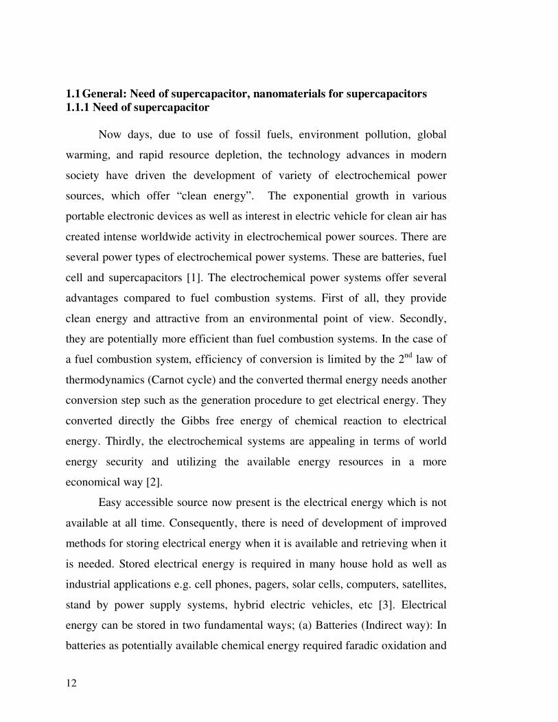
Fig. 1.1 Ragone chart showing logarithmic plot of energy density Vs. power
density for various energy-storage devices [7].
Fig. 1.1 shows Ragone chart, which is a bubble chart used for
performance comparison of various energy storing devices [Both axes are
15
logarithmic, which allows comparing performance of very different devices.].
On such a chart the values of energy density (in Wh.kg-1) are plotted versus
power density (in W.kg-1). Conceptually, the vertical axis describes how much
energy is available, while the horizontal axis shows how quickly that energy
can be delivered. Powering a small light-bulb may require low amounts of
power, but the power should be delivered slowly enough to operate a flashlight
for minutes or hours of use (batteries). Conversely, a high speed electronic
switch inside a computer may require very little energy to activate; yet it must
be delivered rapidly enough to complete the transaction in mere microseconds
(supercapacitors). These two devices would find themselves at opposite corners
of the Ragone chart. Supercapacitors offer high power density when compared
to battery systems and also have relatively large energy density compared to
conventional capacitors [8, 9].
Supercapacitor offers advantages over the conventional capacitor and
battery [10].
1 Specific capacitance in several Farads to several hundred Farads (105-106
times ordinary capacitors).
2 Virtually unlimited cycle life - can be cycled millions of time.
3 Low impedance – enhances load handling when put in paralleled with a
battery.
4 Rapid charging – discharging, supercapacitors charge in seconds.
5 High power density.
6 Simple charging methods. No special charging or voltage detection
circuits required like batteries.
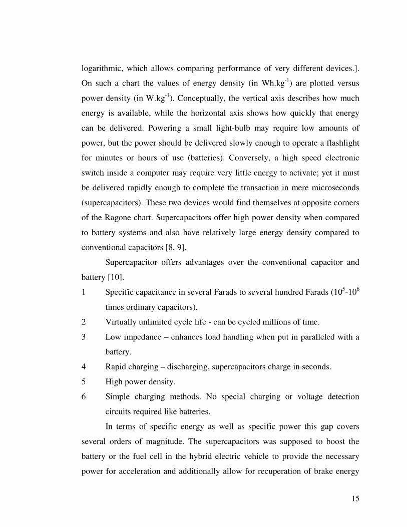
In terms of specific energy as well as specific power this gap covers
several orders of magnitude. The supercapacitors was supposed to boost the
battery or the fuel cell in the hybrid electric vehicle to provide the necessary
power for acceleration and additionally allow for recuperation of brake energy
16
(schematic diagram shown in fig. 1.2), also particularly associated with cellular
phones and pace-maker for reduction of the size of batteries [11,12]. Today
several companies such as Maxwell Technologies, Siemens Matsushita, HEC,
Panasonic, TOKIN and several others are investing in supercapacitor
development. The applications envisaged are to principally boost components
supporting batteries or replacing batteries, primarily in electric vehicles. In
addition, alternative applications of supercapacitors where they compete not
with batteries, but with conventional capacitors are appearing up and show
considerable market potential.
Fig. 1.2 Schematic diagram of hybrid electrical vehicle.
Now a day’s considerable interest has been placed on developing high
energy and power density electrochemical energy source, due to small size and
shape as well as long term reliability and environmental compliance. Hence
main goal is to increase the energy density of an electrochemical device namely
as ‘supercapacitor’ furthermore to develop electrode materials with high
specific surface area, low cost and high reversible redox reaction [13].
1.1.2 Nanomaterials for supercapacitors
Technology in the present century requires the miniaturization of the
devices in to nanometer size with dramatically enhanced ultimate performance.
Nano-phase or nanostructured materials, a new branch of materials research, is
17
attracting in great areas such as solar cells, sensors, electronics, optics, etc [14-
16]. Nanocrystalline materials are not only significantly interesting but also
hold great potential for various industrial applications. The properties of the
material in nanocrystalline form are quite different and often superior to those
of conventional coarse grained crystalline materials. Because of extremely
small dimensions, a large fraction of atoms in these materials are located in the
grain boundaries and confirms special attributes. Nanocrystalline materials are
of great interest because; the function and performance of the material are
strongly dependent on its morphology, size and shape. Nanometersized
materials have recently gained a considerable amount of attention of their
unique physical and chemical properties, because of their large surface to
volume ratio and quantum size effect. A nanocrystalline structure offers a
comparatively large internal surface area, which is advantageous for many
applications where a good accessibility to the film surface becomes necessary.
Nanocrystalline and porous materials as electrode material exhibit good
electrochemical performance because these materials possess both a high
surface area and pores which are adapted to the size of ions [17-19].
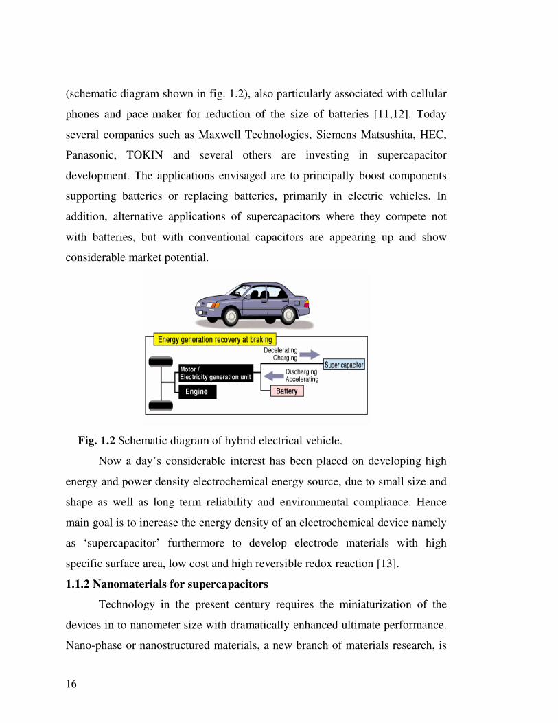
Assemblies of low-dimensional building blocks (nanodots, nanowires,
nanobelts, nanotubes, etc.) into hierarchical architectures on various substrates
have great interest because of the demands for many practical applications in
functional devices. To synthesize nanomaterials various methods are under
consideration, which are divide in two processes as follows: the particles can
either be built from separate atoms (an approach from the “bottom-up”) or by
various dispersion and aggregation procedures (an approach from the “top-
down”). The approach from the “bottom-up” largely pertains to chemical
methods of preparation of nanosize particles, whereas the approach from the
“top-down” is typical of physical methods. Naturally, the proposed division is
rough and fig. 1.3 illustrates both schematic approaches. Preparation of
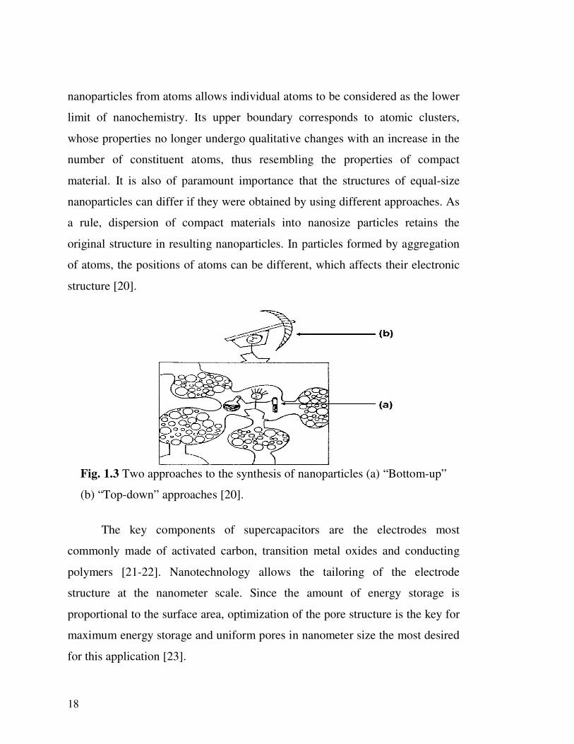
18
nanoparticles from atoms allows individual atoms to be considered as the lower
limit of nanochemistry. Its upper boundary corresponds to atomic clusters,
whose properties no longer undergo qualitative changes with an increase in the
number of constituent atoms, thus resembling the properties of compact
material. It is also of paramount importance that the structures of equal-size
nanoparticles can differ if they were obtained by using different approaches. As
a rule, dispersion of compact materials into nanosize particles retains the
original structure in resulting nanoparticles. In particles formed by aggregation
of atoms, the positions of atoms can be different, which affects their electronic
structure [20].
Fig. 1.3 Two approaches to the synthesis of nanoparticles (a) “Bottom-up”
(b) “Top-down” approaches [20].
The key components of supercapacitors are the electrodes most
commonly made of activated carbon, transition metal oxides and conducting
polymers [21-22]. Nanotechnology allows the tailoring of the electrode
structure at the nanometer scale. Since the amount of energy storage is
proportional to the surface area, optimization of the pore structure is the key for
maximum energy storage and uniform pores in nanometer size the most desired
for this application [23].

19
1.1.3 Thin Film
Any solid system possesses at most two dimensional orders or
periodically is called as a “thin film”. The third dimension, being the
thickness is very small compared to other two dimensions. Properties of
thin film often differ significantly from those of bulk due to surface and
interface effects, which may dominate the overall behavior of the films [24].
Thin films are used for number of applications in various fields such as, A. R.
coating, interference filters, polarizer, narrow band filters, solar cell, photo-
detectors, wave guide coating, photo-thermal solar coatings, magnetic films,
superconductivity, high temperature wear resistance films, hard coatings,
battery electrodes, electrochemical capacitor electrodes, etc [25].
Considerable progress is being made in surface physics and surface
characterization, which is naturally of great importance in the study of materials
in a configuration with a large surface to volume ratio, (i.e. thin film). These
developments have encouraged many laboratories; begin to examine solid-state
surface phenomena, as distinct from bulk, while simultaneously observing the
surface structure [24-26]. The significance of such studies to solid thin films
and their application is obvious, as thin-film properties are often dominated by
surface phenomena.
1.2 Literature survey on TiO2, RuO2 and TiO2-RuO2 thin films
1.2.1 Literature survey on synthesis of TiO2 and RuO2 thin films.
1.2.1. (a) Literature survey on nanocrystalline TiO2 thin films
Nanometer sized TiO2 has been one of the most extensively studied
oxides because of its remarkable optical and electrical properties and its
potential utilization in as low cost material for photocatalysis [27-29],
photovoltaic cells [30], dye sensitized solar cells (DSSC) [31] and gas sensors
[32]. A recent interest has been focused on an amphiphilic TiO2 surface induced

20
by UV irradiation, which is expected to be applicable to windshield and mirrors
for vehicles [33]. Due to the wide band-gap (Eg = 3.2 eV), TiO2 is a very
attractive material for the development of optoelectronic devices, such as light
emitting diodes [34], and photodetectors [35]. Many researchers [36-38] are
actively involved in synthesis of porous/mesoporous TiO2 thin film working
electrodes in solar cells due to its high surface area, which provides absorption
of large number of dye molecules result in better performance in
photoelectrochemical cells. There are seven known polymorphs of TiO2
observed over the lifetime of the electrode; six of which have distinct
structures, such as anatase (β-TiO2), rutile (α-TiO2), brookite type (γ- TiO2),
pyrite (Pa3), α-PbO2, baddeleyite (ZrO2) type, fluorite, etc [39]. All of them
have the same fundamental octahedral structural units except for their three-
dimensional arrangements. Each phase, however, has different physical
properties such as refractive index, dielectric constant, photochemical activity
etc [40]. Among these crystalline phases, the anatase phase exhibits a high
photocatalytic activity and thus has recently attracted much attention in the field
of photocatalysts for decomposition of environmental pollutants and dye
sensitized solar cells (DSSC) [41]. As far catalysis, photocatalysis and dye
sensitized solar cells concerned, a rutile TiO2 has attracted less attention [42]
due to the expectation that the rutile phase may exhibit lower electrochemical
performance than the anatase phase [43]. However, Rutile TiO2 has some
advantages over anatase such as high refractive index, higher chemical stability,
cheaper production cost etc.
Consequently, a low cost preparation and fixation of the TiO2 with nano-
sized particle is necessary for practical application. Recently, much emphasis
has been put on the soft solution chemical processes for the preparation of
advance inorganic materials such as pervoskite-type-oxide, spinel type oxides,
and nanodots with quantum size effects. Therefore, these soft chemical

21
processes are important for the preparation and fixation of TiO2 particles.
Performance of TiO2 for technical applications is strongly influenced by its
morphology, crystallite size, crystalline phase and impurity type concentration.
Porous, nanocrystalline TiO2 is of great interest because; the function and
performance of the material are strongly dependent on its morphology [44].
Accordingly, the advance of synthetic methods, in which the crystalline phase,
size and shape of the TiO2 nanocrystals can be controlled, is of importance. In
recent years, many studies related to the synthesis of anatase TiO2 have been
focused on the control of morphology as well as particle size.
Since this work is concerned with chemical methods for synthesis, the
literature survey is limited to the chemical methods only. Although, the
commercial methods of TiO2 thin film fabrication used today are the gas phase
techniques such as sputtering [45], and MOCVD [20], many workers have
employed low cost soft solution chemical methods for preparation TiO2 thin
films. Such processes include thermal and anodic oxidation of titanium [46],
electron beam evaporation [47], chemical vapor deposition [48], sol–gel [49,
50], chemical bath deposition (CBD) [51-61], successive ionic layer adsorption
and reaction (SILAR) method [62-65], spray paralysis [66], electrochemical
deposition [67], etc. Many workers have attracted towards the CBD method for
preparation of TiO2 thin films due to its simplicity and low cost, besides the
capability to achieve large area coating. Mane et al. [51] have grown compact
TiO2 film and used for 3-D solar cells by using CBD method at room
temperature from TiCl3 as precursor solution and pH maintained at 1 to 2.
Lokhande et al. [52] obtained amorphous TiO2 thin films on ITO coated
substrate by slow hydrolysis of TiCl3 solution at room temperature. It was
found that with increasing pH, rate of hydrolysis was increased resulting into
TiO2 precipitate formation in bulk of solution without film formation on the
substrates, and suitable pH range was found to be 3-3.5. Sankapal et al. [54, 55]
22
have obtained anatase TiO2 thin films by CBD method using peroxo-titanium
complex as a single precursor maintained at 298 K and annealed at 773 K for 1
h for large-area photon conversion. Pathan et al. [56] have studied structural
and morphological properties of the TiO2 thin films by CBD method at room
temperature. The effect film thickness on the properties of the TiO2-anatase
films prepared on Si (100) wafers using CBD method for dielectric application
has been studied by Souni et al. [57]. Crystal growth of anatase-type TiO2 in
aqueous solutions of titanium tetrafluoride and titanyl sulfate at 333 K by CBD
method was applied for low-temperature preparation of dye-sensitized solar
cells by Watanabe et al. [58]. Crystalline TiO2 thin films were obtained on glass
and various kinds of organic substrates at 313 K by CBD method from aqueous
solutions of titanium tetrafluoride by Shimzu et al. [59]. Gao et al. [60]
prepared TiO2 thin films onto the glass substrate from aqueous peroxotitanate
solution by CBD method at room temperature. However, anatase TiO2 films
obtained after heating the films at 773 K. Rutile and anatase TiO2 films were
successfully fabricated in TiOSO4 aqueous solution containing urea at near
room temperature (333 K) by Yamabi et al. [61]. They studied molar ratio of
urea to TiOSO4 in the precursor solutions which determined the crystal phase of
the TiO2 films by CBD method. In order to avoid material consumption in CBD
method, due to bulk precipitation in the solution, many workers adopted SILAR
method. Kale et al. [62] obtained amorphous TiO2 thin films on glass substrate
by titanium isopropoxide solution using SILAR method. Photoelectrochemical
properties of the TiO2 thin films by SILAR method onto ITO coated substrate
have been studied by Pathan et al. [63]. Kim et al. [64] have fabricated TiO2
thin films by SILAR method assembled with TiO2 nanoparticles and oppositely
charged polyelectrolytes or titanium (IV) bis (ammonium lactato) dihydroxide
(TALH) and characterized for structural, morphological and optical properties.

23
Photocatalytic activity of TiO2 nanoparticles thin films on silicon wafers have
been studied by Park et al. using the SILAR method [65].
These processes have been used environmentally benign conditions.
Therefore, these soft chemical processes are important for the preparation and
fixation of TiO2 particles.
1.2.1 (b) Literature survey on RuO2 thin films
A polyvalent hard metal, ruthenium is a member of the platinum group.
Ruthenium is a chemical element in the periodic table that has the symbol Ru
and atomic number 44. The oxidation state of ruthenium range from +1 to +8,
though +2, +3 and +4 are more common. The ruthenium (IV) oxide (RuO2),
oxidation states +4 is the stable oxide at room temperature and in a wide
temperature range. RuO3 is unstable at room temperature and radially
decomposes to give RuO2 and O2. Ruthenium oxide is generally used as a
catalyst in various industrial applications or an electrode in electrochemical
process. RuO2 is highly reactive with reducing agents due to its oxidizing
properties. Ruthenium dioxide exhibits a rare combination of material
properties; including a relatively low resistivity (~35 µΩ.cm at room
temperature), good thermal stability and high resistance to chemical corrosion
[68]. These desirable characteristics have attracted attention for its application
in diverse fields both in the electronics and chemical industry. In the area of
microelectronics, RuO2 has been proposed for use as an interdiffusion barrier
and also as a precision resistor element [69–71]. Recent studies have also
demonstrated its utility as a contact electrode material in ferroelectric random
access memory devices that offers superior polarization fatigue properties with
very low leakage current [72–74]. Ruthenium dioxide was investigated by a
number of authors, because of its extremely high corrosion resistance in
concentrated acids and high dielectric constant required for capacitors in very-
large-scale integrated circuits (VLSIs). Recent work on ruthenia shows that it is

24
applicable in VLSI as thick film resistor. Also it is used in Y-Ba-Cu-O (YBCO)
superconductor as a buffer layer. Bulk RuO2 has a tetragonal structure
(a=b=0.4499 nm, c=0.3107 nm), and is closely lattice matched with
isostructural rutile oxides, such as TiO2 (a=b=0.4594 nm, c=0.2958 nm).
1.2.2 Literature survey on metal oxide, composite thin film based
supercapacitors
1.2.2 (a) Literature survey on RuO2 and metal oxide thin film based
supercapacitors
The concept and use of RuO2 as an supercapacitor material can be traced
on the paper by Trasatti and Buzzanca in 1971 [75-76]. Galizzioli et al. [77]
first recognized that the current response of thermally prepared anhydrous
ruthenium oxide film was similar to that of an ideal capacitor. In recent years,
[78, 79] the use of hydrous ruthenium oxide as an electrode material was
investigated. It was found that powder form of amorphous and hydrous
ruthenium oxide formed by the sol–gel method was a promising for
supercapacitor with high power density and energy density [80, 81]. A specific
capacitance of 768 Fg-1 has been obtained from an amorphous hydrous
ruthenium oxide prepared by sol-gel method [82]. A chemical oxidation of
RuCl3:xH2O with H2O2, is reported by Chang et al. [83], for the synthesis of
hydrous ruthenium oxide denoted as RuOx:nH2O. The annealed RuOx:nH2O
with the non-stiochoimetric amorphous structure exhibits the ideal capacitive
performance i.e., highly electrochemical reversibility, high-power property, and
excellent stability with specific capacitance >500 Fg-1.
In thin film form, Hu et al. [84–86], and Park et al. [87] have been
successfully employed electrochemically deposited hydrous ruthenium oxide
for supercapacitors (specific capacitance = 788 Fg-1). Fang et al. [88] have
prepared ruthenium oxide film electrode by organic precursor method and
obtained maximum specific capacitance of 593 Fg-1 and interfacial capacitance
25
of 4 Fcm-2. Kim et al. [89] have prepared ruthenium oxide film electrode with
an average specific capacitance of 650 Fg-1 and good high rate capability by
electrostatic spray deposition. It is also seen that, performance of supercapacitor
depends upon the thickness of the film deposited material, i.e. it increases with
increase in thickness. In sol–gel process, aqueous RuCl3:xH2O powder and
NaOH solutions were used and maintained at pH~7.The film was annealed at
temperature of 373 K. The maximum energy density of RuO2.xH2O based
supercapacitor was 96 J.g-1. It is possible to prepare hydrous ruthenium oxide
by using cyclic voltametry (CV). The deposition of oxide films depends upon
several factors like temperature, pH of the deposition bath, potential ranges,
scan rates of CV and also concentration of RuCl3 solution used [90, 91].
In sputtering technique Ru target was presputtered by Ar ion plasma to
avoid surface oxide contamination. Ruthenium oxide film was grown on the
substrate by reactive sputtering of Ar/O2 at room temperature. The capacitance
per volume of the RuO2/Lipon/RuO2/Pt TFSC (Thin film Supercapacitor) at the
first cycle was 38 mF.cm-2 [92]. Ruthenium oxide films electrode was prepared
by spraying, a mole of RuCl3 in ethanol solvent with 3 mole Na (OC2H5) in
ethanol [93]. Ruthenium ethoxide solution was spread onto heated substrate by
an airbrush and annealed at about 15 min and then dipped into boiling water for
about 1 min. The highest specific capacitance of 593 F.g-1 was obtained from
the film electrode grown at 473 K [94]. In electrostatic spray deposition (ESD),
0.01-0.3 M RuCl3:XH2O solution is spread on the heated substrate of Pt, coated
silicon. The average specific capacitance was found to be 650 Fg-1 [95]. In sol-
gel process specific capacitance 768 Fg-1 was obtained. A NaOH solution added
to RuCl3:xH2O solution to maintain the pH~7 [96]. Colloidal method was also
adopted to prepare ruthenium oxide [97]. Specific capacitance 551 Fg-1 was
found for unhydrous amorphous RuO2 prepared by spray pyrolisis technique
(SPT) at 573 K by Gujar et al. [98]. Lee et al. [99] adopted simple chemical

26
bath deposition method to synthesize hydrous RuO2 having specific capacitance
500 Fg-1 and Patake [100] et al. reported 50 Fg-1 specific capacitance for RuO2
electrode synthesized by M-CBD method. Although ruthenium oxide allows the
attainability of higher capacitance than all other oxide materials, the rarity of
the metal and its very high cost have prompted researchers to identify
compounds in which ruthenium could be replaced by cheaper transition metal
elements like Ni, Co, Mn etc. Table 1.1 shows the specific capacitance values
exhibited by virgin metal oxides using preparation methods with the electrolyte
used.
1.2.3 (b) Literature survey on composite and TiO2-RuO2 thin film based
supercapacitors
Moreover, a relatively high-frequency response is an essential
requirement for supercapacitors delivering pulse power which should be
achieved by reducing the equivalent series resistance (ESR) employing suitable
electrode materials [101] with a proper utilization of the electroactive species.
Accordingly, developing and designing active materials as well as electrodes
meeting the above requirements becomes an interesting subject for many
electrochemists. The main drawback of hydrous ruthenium oxide is its high
cost. To overcome this, a strategy is to prepare composites in which particles of
hydrous ruthenium oxide are deposited on other materials of lower price, e.g.
carbons with different surface textures, or cheap oxides such as nickel oxide,
titanium oxide etc. The supports are also electrochemically active electrode
materials but they show lower specific capacitances compared to hydrous
ruthenium oxide. The idea of the composite is try to combine the high specific
capacitance of hydrous ruthenium oxide with a good dispersion over other
oxide, in order to get electrode materials with high capacitance and low or
moderate price.

27
Arabale et al. [102] reported the supercapacitive behavior of ruthenium
oxide functionalized multiwalled carbon nanotubes (Ru/MWNT), for the first
time. By using cyclic voltammetry and impedance measurements, they have
found that the capacitance of MWNTs can be increased from 30 to 80 Fg-1 after
ruthenium oxide functionalization. Wang et al. [103] reported hydrous
ruthenium–tin oxides (denoted as (Ru–Sn)O2·nH2O)were synthesized under a
mild hydrothermal condition. The maximum specific capacitance 820 Fg-1 was
achieved. Preparation of RuOxHy /carbon black nanocomposite material was
performed by Panic et al. [104] by using impregnation method starting from
RuOxHy sol as a precursor. Black pearls 2000(BP) and Vulcan XC-72 R (XC)
were used as supporting materials. Samples of the composite were calcined in
nitrogen atmosphere at temperatures from 403 to 723 K. The highest specific
capacitance of electrode is about 700 Fg-1 was registered for RuOxHy supported
on BP and calcined at 573 K while four times lower values was obtained for
RuOxHy supported on XC. Mixtures of RhOx + Co3O4 have been
electrochemically studied by Souza et al. [105] in acid solution as a function of
composition. The electrodes were prepared by thermal decomposition at 673 K
of mixtures of nitrate precursors. Electrodes of this kind have been found to
perform as good materials in supercapacitor applications, exhibiting specific
capacitances of 500–800 Fg-1 over to 20–60 mol.% RhOx composition range.
Hu et al. [106] studied the electrochemical energy storage and delivery on the
electrodes composed of hydrous ruthenium oxide or activated carbon–hydrous
ruthenium oxide (AC–RuOx) composites are found to strongly depend on the
substrate employed. The maximum specific capacitance (CS,RuOx) of
RuOx:nH2O, 1580 Fg-1 (measured at 1 mV.s-1), very close to the theoretical
value, was obtained from an AC–RuOx/RuOx/Au/SS electrode with 10 wt.%
sol–gel-derived RuOx:nH2O annealed in air at 473 K for 2 h. A two-step
hydrothermal process was reported by Hu et al. [107] to synthesize hydrous
28
30% RuO2 –70% SnO2 composites with much better capacitive performances
than those fabricated through the normal hydrothermal process, co-annealing
method, or modified sol–gel procedure. A very high specific capacitance of
RuO2 (CS, Ru), ca. 1150 Fg-1, was obtained. Fang et al. [108] reported
significant enhancement in supercapacitor performance has been achieved via a
new RuO2 nanocomposite materials prepared by direct ruthenium sputtering on
arrayed multi-walled carbon nanotubes supported by Ti-buffered Si wafer.
Well-dispersed and strongly adhered RuO2 NPs have been densely populated on
CNxNTs to obtain the overall specific capacitance (1380 Fg-1-RuO2), charging–
discharging rate (up to 600 mV.s-1) and operation stability (5000 cycles).
Amorphous Ru1−yCryO2/TiO2 nanotube composites were synthesized by loading
different amount of Ru1−yCryO2 on TiO2 nanotubes via a reduction reaction of
K2Cr2O7 with RuCl3:nH2O at pH 8, followed by drying in air at 423 K. A
maximum specific capacitance 1272 Fg-1 was reported with the proper amount
of Ru1−yCryO2 loaded on the TiO2 nanotubes by Bo et al. [109]. Electrochemical
characteristics of lithium ruthenate (LixRuO2+0.5x·nH2O) for electrochemical
capacitors electrode material were prepared by Zhao et al. [110]. The specific
capacitance of 391 F/g can be delivered at 1 mA charge–discharge current for
LixRuO2+0.5x·nH2O electrode with an energy density of 65.7 Wh.kg-1.
Morishita et al. [111] invented new electrode materials for
supercapacitor, tungsten carbide (WC) and molybdenum carbide (Mo2C) coated
by porous carbon, were prepared through a simple heat treatment of the mixture
of K2WO4 and K2MoO4, respectively, with hydroxy propyl cellulose. The
carbon-coated carbide gave a high capacitance in 1 mol./L H2SO4 electrolyte, as
about 350 Fg-1 for carbon-coated WC and 550–750 Fg−1 for carbon coated
Mo2C.
The energy storage of activated carbon modified with a semiconducting
oxide TiO2 is studied by Liang et al. [112]. The composite was prepared by

29
mixing nanosize TiO2 and activated carbon through a means of ultrasonic
vibration in ethanol solution for 30 min. It was found that with modification of
TiO2, the specific capacitance of activated carbon measured at 0.65 mA.cm-2
was increased from 47 to 63 Fg-1. Nanostructured and microporous nickel–
manganese oxide (NMO) and cobalt–manganese oxide (CMO) were deposited
by potentiodynamic method onto inexpensive stainless steel substrate at scan
rate 200 mV.s-1. Maximum specific capacitance (SC /Cs) values of 621 and 498
Fg-1 were obtained with NMO and CMO electrodes, respectively reported by
K.R. Prasad et al. [113]. Nickel–cobalt oxides/carbon nanotube (CNT)
composites were prepared by adding and thermally decomposing nickel and
cobalt nitrates directly onto the surface of carbon nanotube/graphite electrode to
form nickel and cobalt oxides. The effect of Ni/Co molar ratio on specific
capacitance of the composite electrode was investigated by Fan et al. [114] and
the highest specific capacitance 569 Fg-1 (at 10mA.cm-2) is obtained at Ni/Co
molar ratio = 1:1.
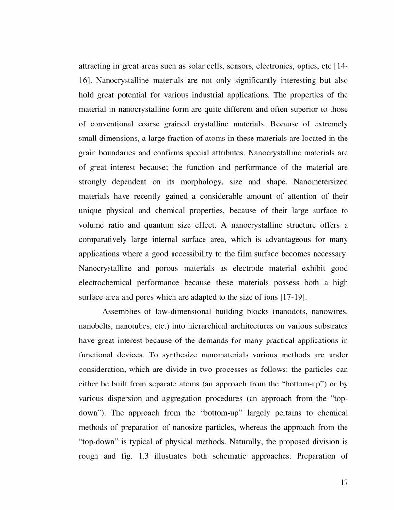
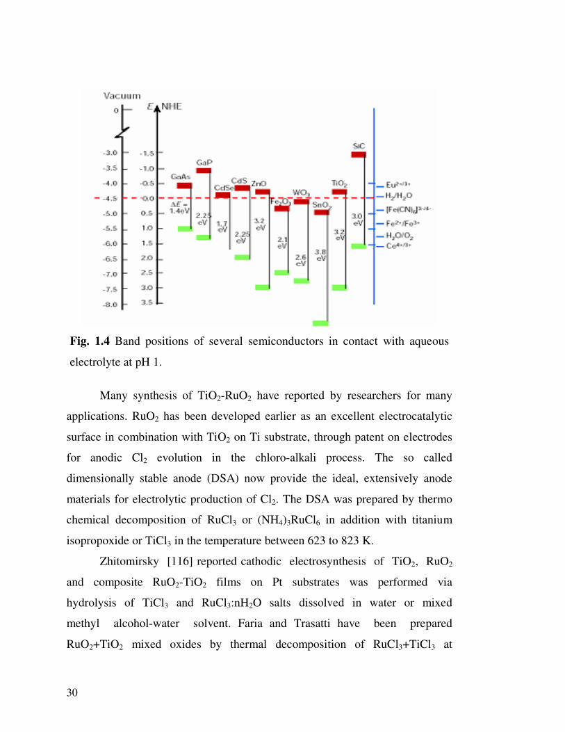
One of the most semiconducting materials for composite electrode is
TiO2 because of its high stability towards photocorrosion and its favorable band
gap energy and flat band potential, shown in fig.1.4 [115].
30
Fig. 1.4 Band positions of several semiconductors in contact with aqueous
electrolyte at pH 1.
Many synthesis of TiO2-RuO2 have reported by researchers for many
applications. RuO2 has been developed earlier as an excellent electrocatalytic
surface in combination with TiO2 on Ti substrate, through patent on electrodes
for anodic Cl2 evolution in the chloro-alkali process. The so called
dimensionally stable anode (DSA) now provide the ideal, extensively anode
materials for electrolytic production of Cl2. The DSA was prepared by thermo
chemical decomposition of RuCl3 or (NH4)3RuCl6 in addition with titanium
isopropoxide or TiCl3 in the temperature between 623 to 823 K.
Zhitomirsky [116] reported cathodic electrosynthesis of TiO2, RuO2
and composite RuO2-TiO2 films on Pt substrates was performed via
hydrolysis of TiCl3 and RuCl3:nH2O salts dissolved in water or mixed
methyl alcohol-water solvent. Faria and Trasatti have been prepared
RuO2+TiO2 mixed oxides by thermal decomposition of RuCl3+TiCl3 at

31
723 K [117]. Kristof et al. [118] reported the processes for formation of
RuO2/TiO2 coatings from precursor salts dissolved in isopropanol were
followed by combined thermo analytical and mass-spectrometric methods.
Miao et al. [119] reported epitaxial ruthenium oxide thin films have been
grown on TiO2 substrates by chemical vapor deposition at temperatures 573 K
as low as using tris(2,2,6,6-tetramethyl-3,5-heptanedionato) ruthenium
[Ru(TMHD)3] as a precursor with oxygen carrier gas. Song et al. [120] studied
effect of glass frit on corrosion resistance of Ti/TiO2/IrO2–RuO2 thin films. The
films were deposited on plasma sprayed TiO2 buffer layer above Ti metal by the
sol–gel and dip-coating method. Panic et al. [121] reported synthesis and
characterization of RuO2 and TiO2 sols of different aging times, obtained by
forced hydrolysis of appropriate chloride salts, was performed by transmission
electron microscopy (TEM). The aging time of TiO2 sols was observed to affect
the size of particles as well as the crystallinity of the solid phase of the sols. An
RuO2/TiO2(110) ultrathin film, epitaxially grown in ultrahigh vacuum by
reactive deposition of Ru3(CO)12 in an oxygen atmosphere (2×10⁻⁶ mbar) at 573
K, has been prepared by Rizzi et al. [122]. The influence of the aging time of
RuO2 and TiO2 sols used for the preparation of (40% RuO2+60% TiO2):Ti
anodes by the sol-gel procedure on the electrochemical properties and behavior
for the chlorine evolution reaction of obtained anodes was studied by V. Panic
et al. [123, 124]. Faria et al. [125] are reported the effect of mixing Ru and Ce
has been investigated by systematically substituting Ce for Ti in 30 mol% RuO2
+ 70 mol% TiO2 by thermal decomposition of aqueous acid solutions of the
chlorides as precursors using Ti as a support. Phvulescu et al. studied the
activity of the RuO2-TiO2 and RuO2-SiO2 membrane catalysts in oxidation with
air of the isopropylic alcohol was determined at temperatures ranging from 373
to 393 K. The RuO2-TiO2 and RuO2-SiO2 membranes were prepared by the sol-
gel process and supported on microporous glass membranes [126]. Yong-gang
32
et al. [127] reported a synthesis of RuO2/TiO2 composite by loading various
amounts of RuO2 on TiO2 nanotubes. The symmetric supercapacitors based on
these nanocomposites were fabricated by using gel polymer PVA–H3PO4–H2O
as electrolyte, a maximum specific capacitance of 1263 Fg-1 was obtained for
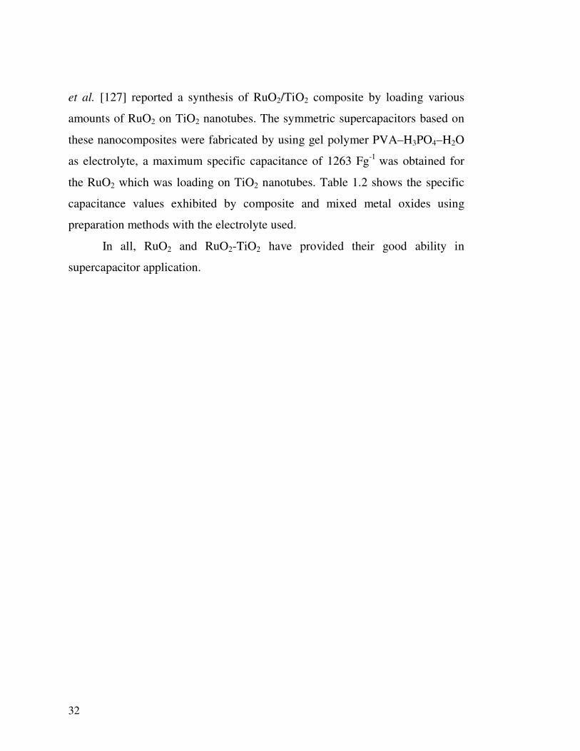
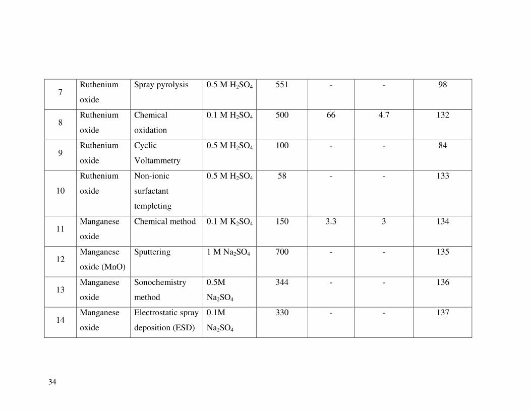
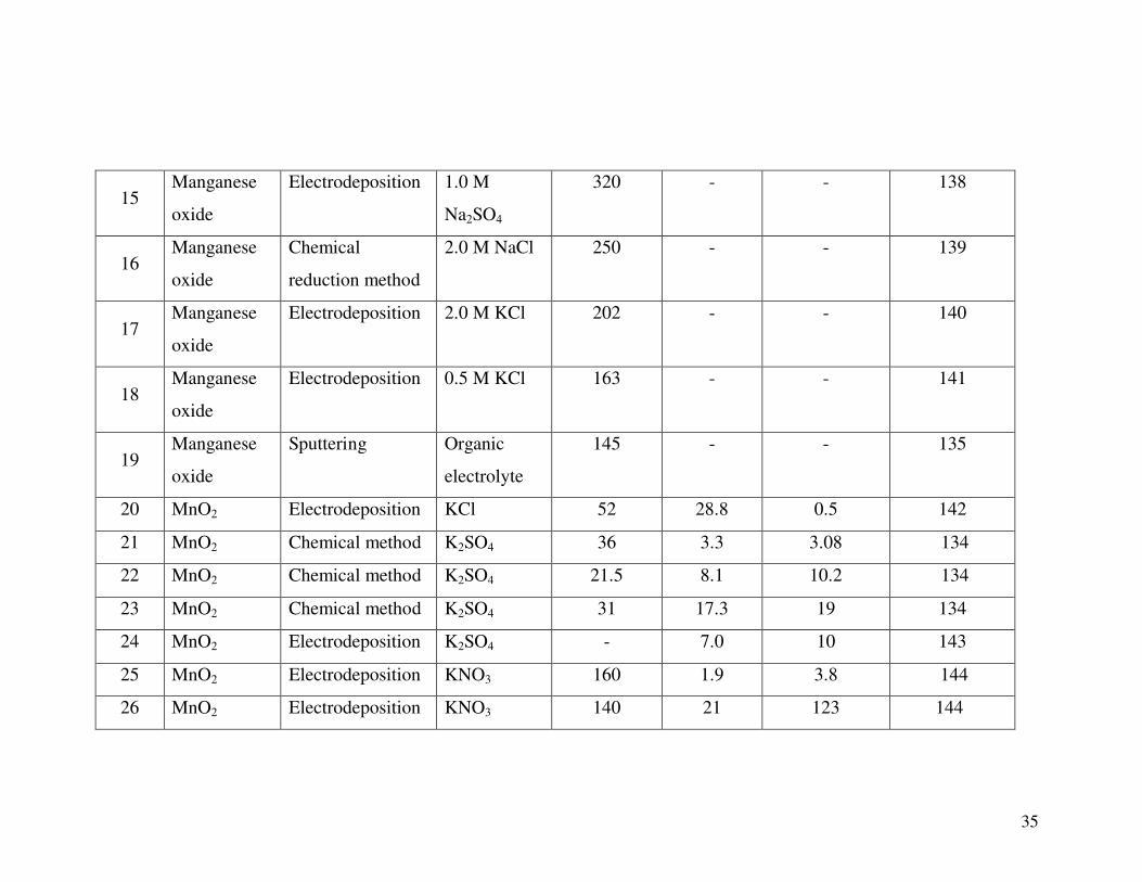
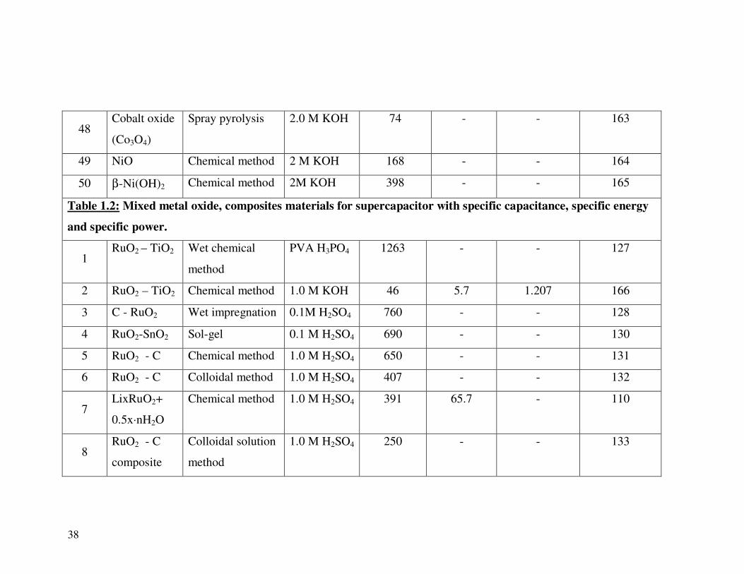
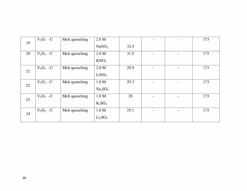
the RuO2 which was loading on TiO2 nanotubes. Table 1.2 shows the specific
capacitance values exhibited by composite and mixed metal oxides using
preparation methods with the electrolyte used.
In all, RuO2 and RuO2-TiO2 have provided their good ability in
supercapacitor application.

33
Table 1.1: Virgin metal oxide materials for supercapacitor with specific capacitance, specific energy and specific
power.
Sr.
No.
Material Method of
preparation
Electrolyte Specific
capacitance
(Fg-1
)
Specific
energy
(Wh.kg-1
)
Specific
power
(kW-1
kg)
Reference
1 Ruthenium
oxide (RuO2)
Electrodeposition 0.1 M H2SO4 788 - - 93
2 Ruthenium
oxide
Electrophoretic
deposition
1.0 M H2SO4 734 - - 128
3 Ruthenium
oxide
Sol-gel 0.5 M H2SO4 720 26.7 - 96
4 Ruthenium
oxide
Electrostatic spray
deposition
0.5 M H2SO4 650 17.6 4 129
5 Ruthenium
oxide
Electrodeposition 0.5M H2SO4 599 17.6 - 130
6 Ruthenium
oxide
Thermal
decomposition
0.5 M H2SO4 593 - - 131
34
7 Ruthenium
oxide
Spray pyrolysis 0.5 M H2SO4 551 - - 98
8 Ruthenium
oxide
Chemical
oxidation
0.1 M H2SO4 500 66 4.7 132
9 Ruthenium
oxide
Cyclic
Voltammetry
0.5 M H2SO4 100 - - 84
10
Ruthenium
oxide
Non-ionic
surfactant
templeting
0.5 M H2SO4 58 - - 133
11 Manganese
oxide
Chemical method 0.1 M K2SO4 150 3.3 3 134
12 Manganese
oxide (MnO)
Sputtering 1 M Na2SO4 700 - - 135
13 Manganese
oxide
Sonochemistry
method
0.5M
Na2SO4
344 - - 136
14 Manganese
oxide
Electrostatic spray
deposition (ESD)
0.1M
Na2SO4
330 - - 137
35
15 Manganese
oxide
Electrodeposition 1.0 M
Na2SO4
320 - - 138
16 Manganese
oxide
Chemical
reduction method
2.0 M NaCl 250 - - 139
17 Manganese
oxide
Electrodeposition 2.0 M KCl 202 - - 140
18 Manganese
oxide
Electrodeposition 0.5 M KCl 163 - - 141
19 Manganese
oxide
Sputtering Organic
electrolyte
145 - - 135
20 MnO2 Electrodeposition KCl 52 28.8 0.5 142
21 MnO2 Chemical method K2SO4 36 3.3 3.08 134
22 MnO2 Chemical method K2SO4 21.5 8.1 10.2 134
23 MnO2 Chemical method K2SO4 31 17.3 19 134
24 MnO2 Electrodeposition K2SO4 - 7.0 10 143
25 MnO2 Electrodeposition KNO3 160 1.9 3.8 144
26 MnO2 Electrodeposition KNO3 140 21 123 144

36
27 MnO2 Chemical method KNO3 - 5.86 42.1 145
28 MnO2 Chemical method H2SO4 - 7.37 62.8 145
29 MnO2 Chemical method KNO3 - 13.5 120.1 145
30 MnO2 Sputtering LiOH 62.4 19.5 - 146
31 MnO2 Chemical method K2SO4 21 11.7 - 147
32 LiMn2O4 Sol-gel Li2SO4 56 10 2 148
33 Nickel oxide
(NiO)
Electrodeposition 1.0 M KOH 277 - - 149
34 Nickel oxide Electrochemical
precipitation
1.0 M KOH 146 - - 150
35 Nickel oxide Sol-gel 1.0 M
2.0 KOH
125 - - 151
36 Nickel oxide Calcination 2.0 M KOH 120 - - 152
37 Ni(OH)2 Electrodeposition 3.0 M KOH 578 - - 153
38
Ni-C Chemical bath
deposition method
(CBD)
BMIM-PF6
RTIL
357 50 0.458 154

37
39 NiFe2O4 CBD 1.0 M
Na2SO3
223 - - 155
40 NiFe2O4 SILAR 1.0 M
Na2SO3
369 - - 155
41 Bismuth
oxide
Electrodeposition 1.0 M NaOH 98 - - 156
42 Bismuth iron
oxide
Electrodeposition 1.0 M NaOH 81
- - 157
43 Fe2O3 Electrosynthesis 0.25 M
Na2SO3
210 - - 158
43 Tin oxide Sol- gel 1.0 M KOH 16 - - 159
45
MnO2 Supramolecular
templeting
method
2 M KOH 299 - - 160
46 Co(OH)2 Electrodeposition 6.0 M KOH 280
23.7 8.1 161
47 Cobalt oxide SILAR 1.0 M KOH 165 6.4 0.47 162
38
48 Cobalt oxide
(Co3O4)
Spray pyrolysis 2.0 M KOH 74 - - 163
49 NiO Chemical method 2 M KOH 168 - - 164
50 β-Ni(OH)2 Chemical method 2M KOH 398 - - 165
Table 1.2: Mixed metal oxide, composites materials for supercapacitor with specific capacitance, specific energy
and specific power.
1 RuO2 – TiO2 Wet chemical
method
PVA H3PO4 1263 - - 127
2 RuO2 – TiO2 Chemical method 1.0 M KOH 46 5.7 1.207 166
3 C - RuO2 Wet impregnation 0.1M H2SO4 760 - - 128
4 RuO2-SnO2 Sol-gel 0.1 M H2SO4 690 - - 130
5 RuO2 - C Chemical method 1.0 M H2SO4 650 - - 131
6 RuO2 - C Colloidal method 1.0 M H2SO4 407 - - 132
7 LixRuO2+
0.5x·nH2O
Chemical method 1.0 M H2SO4 391 65.7 - 110
8 RuO2 - C
composite
Colloidal solution
method
1.0 M H2SO4 250 - - 133

39
9 RuO2-SnO2 DC sputtering 0.5 M H2SO4 88 - - 96
10 Ni - Co CVD 1.0 M KOH 569 - - 114
11 Ni-MnO2 Electrodeposition 1.0 M
Na2SO4
621 - - 113
12 Mn-Ni - Co Co-precipitation 6.0 M KOH 1260 - - 167
13 NiO - RuO2 Co-precipitation 1.0 M KOH 210 - - 168
14 IrO2 – MnO2 Thermal
decomposition
0.5 M H2SO4 550 - - 169
15
Pb-RuO2 Solid state
reaction
0.5 M H2SO4 160 - - 170
16
Co- MnO2 Electrodeposition 0.5 M
Na2SO4
396 - - 171
17 Co – MnO2 Electrodeposition 1.0M
Na2SO4
98 - - 113
18 Co(OH)2/
TiO2
Precipitation
method
6.0 M KOH 229 - - 172
40
19 V2O5 - C Melt quenching 2.0 M
NaNO3
32.5
- - 173
20
V2O5 - C Melt quenching 2.0 M
KNO3
31.5 - - 173
21 V2O5 - C Melt quenching 2.0 M
LiNO3
29.9 - - 173
22 V2O5 - C Melt quenching 1.0 M
Na2SO4
29.3 - - 173
23 V2O5 - C Melt quenching 1.0 M
K2SO4
28 - - 173
24 V2O5 - C Melt quenching 1.0 M
Li2SO4
25.1 - - 173

41
1.3 Orientation and purpose of dissertation
Supercapacitors have been recognized as a unique device exhibiting
high-power characteristics with an acceptable capacity and long cycle life for
energy storage/delivery and management in future power systems. The novel
performance of this device usually resulted from the high specific surface area
as well as the highly reversible redox reactions of the electrode materials. After
scanning through the literature porous activated carbon (AC), hydrous transition
metal oxides, conducting polymers, mixed metal oxides or their composites are
the main components in the electrode materials of supercapacitors. Their ESR
prevents supercapacitors from achieving power densities near to the theoretical
limits. Thus, determining how to lower the ESR of supercapacitors is becoming
an important area of research. Several methods for reducing the ESR already
have been developed, including polishing the surface of the current collector,
chemical bonding the electrode to the current collector and using colloidal thin
film suspensions. In addition, research is going on defining the relationship
between pore size and ESR in electrode materials and determining the intrinsic
ESR of various electrolytes. Accordingly, developing and designing active
materials as well as electrodes meeting the above requirements becomes an
interesting subject for many electrochemists. It is possible to obtain the high
working voltage of the supercapacitors by choosing a proper electrode material.
Both increase of the working voltage and high energy density of the metal
oxide electrode result in a significant increase of the overall energy density of
the supercapacitors. Recently, Wang et al. [127] is reported that the three-
dimensional nanotubes network of TiO2 nanotubes can increase greatly the
utilization of RuO2, and the capacitance profile of the symmetric capacitors
using of RuO2/TiO2 nanotubes as both positive and negative electrodes were
investigated. A maximum specific capacitance of 1263 Fg-1 was obtained for
42
the symmetric supercapacitor fabricated by using gel polymer PVA–H3PO4–
H2O as electrolyte.
Though the amorphous, hydrous ruthenium oxide exhibits excellent
pseudocapacitive behavior with large specific capacitance and good
reversibility, the low abundance and high cost of the precious metal are the
major limitations to commercial application. This has caused the researchers to
find new materials like transition metal oxides, or loading of small amount of
RuO2 in other transition metal oxides or in carbon electrode. Alternatively one
can fabricate the RuO2 electrode by a method having high yield, i.e. by a
method that can deposit material of large area at expense of small quantity of
initial ingredients. Recently there has been an increase interest in
nanocrystalline materials, where the physical properties are changing with size.
Part of this interest is fundamental, due to the great potential offered by group
of materials which are novel by virtue of their physical, rather than their
chemical structure. There are two approaches to produce nanocrystalline (or
amorphous) dimensionally stable anodes (DSA) for supercapacitor application,
“Top-down” (Physical methods) and “bottom-up” (Chemical methods)
approach. The electrochemical behavior of metal oxides results directly from
their morphology, which on the other hand, depends on the preparation
procedure and conditions. In order to improve the electrochemical properties of
the material, the size and distribution of the particles have to be adjusted. A
useful “Bottom-up” approach to coating preparation is based on the chemical
methods.
This work is concerned with the development of supercapacitor
electrodes of RuO2 and TiO2-RuO2 films prepared by “Bottom-up” approach
i.e. using simple chemical method, which can offer the fulfillment of the
requirements of the supercapacitor. Among various other deposition methods,
CBD and SILAR methods have many advantages over physical method. These
43
deposition methods result in pinhole free, uniform and well stoichoimetric
films. Since the basic building blocks are ions instead of atoms, also the
preparative parameters are easily controllable. These methods can be used for
the large area deposition.
Using these methods, it is possible to deposit amorphous, hydrous TiO2,
RuO2 and TiO2-RuO2 thin films by varying different preparative parameters
such as suitable metal ion sources, pH, deposition time and temperature, etc.
The X-ray diffraction (XRD) technique will be used for the phase identification
and crystallite size determination. The chemical bonding in the present material
will be studied by Fourier Transform Infrared Analysis (FT-IR). Surface
morphology of the films will be studied using scanning electron microscopy
(SEM). Optical study of the films will be studied by taking optical absorption
spectrum in the UV-VIS-NIR region. The electrical resistivity will be measured
at different temperatures and activation energy will be calculated. Wettablity
properties of the film surface will be studied my measuring the water contact
angle.
The supercapacitor properties of the RuO2 and TiO2-RuO2 films will be
studied by cyclic voltametry (CV) using Potentiostat, forming a electrochemical
cell comprising platinum as a counter electrode, saturated calomel electrode
(SCE) as a reference electrode in a suitable electrolyte. The effect of electrolyte,
thickness of electrode, scan rate and number of cycles on the performance of
supercapacitor electrode will be studied. The electrochemical impedance
spectroscopic (EIS) study will be carried out to measure ESR, relaxation time
of the formed electrode.
So keeping in mind the valuability of material, present study is
performed to reduce the cost and to increase the specific capacitance. Therefore,
the purpose of research work is to develop the RuO2 and TiO2-RuO2 electrodes,

44
by simple chemical methods that have the great advantage due to low cost and
check their supercapacitive behaviour for commercial application.

45
References
1 A.K. Shukla, S. Sampath, K. Vijaymohanan, Current Sci., 79 (2000) 1656.
2 M. Winter and R.J. Brodd, Chem. Review, 104 (2004) 424.
3 A. Burke, J. Power Sources, 91 (2000) 37.
4 A. Chu and P. Braatz, J. Power Sources, 112 (2002) 236.
5 B.E. Conway, J. Electrochem. Soc., 138 (1991) 1539.
6 B.E. Conway, V. Briss, J. Wojtowicz, J. Power Sources, 66 (1997) 1.
7 http://www.Wikipedia.com/supercapacitor/Regon plot
8 B.E. Conway, Electrochemical Supercapacitors: Scientific Fundamentals
and Technological Applications, Kluwer-Plenum, New York 1999.
9 R. Kotz and M. Carlen, Electrochim. Acta., 45 (2002) 2483.
10 M. Anderman, J. Power Sources, 127 (2004) 2.
11 A.K. Shukla, A.S. Arico, V. Antonucci, Rene. Sust. Ene. Rev., 5 (2001)137.
12 Honda. Ultracapacitor in fuel cell vehicle
http://world.honda.com/FuelCell/FCX/ultracapacitor/ 2007.
13 C. Lin, J.A. Ritter, B.N. Popov, J. Electrochem. Soc., 145 (1998) 4097.
14 Y. Huang, X.F. Duan, Y. Cui, L.J. Lauhon, K.H. Kim, C.M. Lieber,
Science, 294 (2001) 1313.
15 Y. Cui and C.M. Lieber, Science, 291 (2001) 851.
16 X. Duan, Y. Huang, R. Agarwal, C.M. Lieber, Nature, 421 (2003) 241.
17 A.Yamakata, T. Ishibashi, H.Onishi, J. Mol. Cat. A: Chem., 199 (2003) 85.
18 J. Hu and R.G. Gordon, Sol. Cells, 30 (1991) 437.
19 L. Kavan, A. Attia, F. Lenzmann, S.H. Elder, M. Gratzel, J. Electrochem
Soc., 147 (2000) 2897.
20 G. Ozin, Adv. Mater., 4 (1992) 612.
21 H. Kim, J.H. Kim, Y.H. Lee, K.B. Kim, J. Electrochem. Soc., 152 (2005)
A2170.
46
22 S.T. Mayer, R.W. Pekala, J.L. Kascchimitter, J. Electrochem. Soc., 140
(1993) 446.
23 W.G. Pell and B.E. Conway, J. Electroanal. Chem., 500 (2001) 121.
24 K.L. Chopra and I.J. Kaur, “Thin Films Device Applications”. Plenum Press
N. Y. (1983).
25 J. George, “Preparation of Thin Films” Marcel Dekker, Inc. N. Y. (1992).
26 C.D. Lokhande, Mater. Chem. Phys., 27 (1991) 1.
27 T.N. Rao, D.A. Tryk, A. Fujishima, Encyclopedia of Electrochemistry,
Willey-VCH, Weinheim, 6 (2002) 36.
28 A.P. Alivistos, M.R.S Bull., 20 (1995) 23.
29 Y. Cao, W. Yang, Y. Chen, H. Du, P. Yue, Appl. Surf. Sci., 236 (2004) 223.
30 I. Zhitomirsky, J. Mater. Sci., 34 (1999) 2441.
31 B.O’Reagan and M. Gratzel, Nature, 353 (1991) 737.
32 A.M. More, J.L. Gunjkar, C.D. Lokhande, Sen. Act. B., 129 (2008) 671.
33 T. Soki, Y. Hatanaka, D.C. Look, Appl. Phys. Lett., 76 (2000) 3257.
34 Y. Liu, C.R. Gorla, S. Liang, N. Emanetoglu, Y. Lu, H. Shen, M. Wraback,
J. Electron. Mater., 29 (2000) 60.
35 Y. Saito, S. Kambe, T. Kitamura, Y. Wada, S. Yanagida, Sol. Ene. Mater.
Sol. Cells., 83 (2004) 1.
36 M. Okuya, K. Nakade, S. Kaneko, Sol. Ene. Mater. Sol. Cells., 70 (2002)
425.
37 R. Wang, K. Hashimoto, A. Fujishima, Nature, 388 (1997) 431.
38 K.D. Rogers, D.W. Lane, J.D. Painter, A. Chapman, Thin Solid Films, 466
(2004) 97.
39 A. Fujishima and K. Honda, Nature, 238 (1972) 37.
40 L. Castneda, J.C. Alnso, A. Ortiz, A. Andrade, J.M. Saniger, J.G. Banulos,
Mat. Chem. Phy., 77 (2002) 938.

47
41 F. Arendse, P. Comte, M. Jirousek, F. Lenzmann, V. Shklover, M. Gratzel,
J. Am. Ceram. Soc., 80 (1997) 3157.
42 E. Hosono, S. Fujihara, K. Kakiuchi, H. Imai, J. Am. Chem. Soc., 126
(2004) 7790.
43 L. Miao, S. Tanemura, H. Watanabe, Y. Mori, K. Kaneko, S. Toh, J. Cryt.
Growth, 260 (2004) 118.
44 M. Gratzel. J. Sol-gel Sci. Tech., 22 (2001) 7.
45 H. Irie, S. Washizuka, K. Hashimota, Thin Solid Films, 510 (2006) 21.
46 A. Monoy, A. Brevet, L. Imhoff, B. Domenichini, E. Lesniewska, P.M.
Peterlè, M.C. Macro-de-Lucas, S. Bourgeois, Thin Solid Films, 515 (2006)
687.
47 Q. Cai, M. Paulose, O.K. Varghese, C.A. Grimes, J. Mater. Res., 20 (2005)
230.
48 C. Martinet, V. Paillard, A. Gagnaire, J. Joseph, J. Non-cryst. Sol., 216
(1997) 77.
49 P. Alexandrov, J. Koprinarova, D. Todorov, Vaccum, 47 (1996) 1333.
50 R. Espinosa, I. Zumeta, J.L. Santana, F. Marinez-Luzardo, B. Gonzalez, S.
Docteur, E. Vigil, Sol. Ene. Mat. Sol. Cells, 85 (2005) 359.
51 R.S. Mane, Y.H. Hwang, C.D. Lokhande, S.D. Sartale, S.H. Han, Appl.
Surf. Sci., 246 (2005) 271.
52 C.D. Lokhande, E.H Lee, K.D. Jung, O.S. Joo, J. Mater. Sci., 39 (2004)
2915.
53 R.S. Mane, S.J. Roh, O.S. Joo, C.D. Lokhande, S.H. Han, Electrochim.
Acta, 50 (2005) 2453.
54 B.R. Sankapal, M.C. Lux-Steiner, A. Ennaoui, Appl. Surf. Sci., 239 (2005)
165.
55 B.R. Sankapal, S.D. Sartale, M.C. Lux-Steiner, A. Ennaoui, C.R. Chimie, 9
48
(2006) 702.
56 H.M. Pathan, S.K. Min, J.D. Desai, K.D. Jung, O.S. Joo, Mater. Chem.
Phy., 97 (2005) 5.
57 M.E.S. Souni, I. Oja, M. Krunks, J. Mater. Sci: Mater. Elect., 15 (2004) 341.
58 T. Watanabe, H. Hayashi, H. Imai, Sol. Eng. Mater. Sol. Cells., 90 (2006)
640.
59 K. Shimizu, H. Imai, H. Hirashim, K. Tsukum, Thin Solid Films, 351
(1999) 220.
60 Y. Gao, Y. Masuda, Z. Peng, T. Yonezawa, K. Koumoto, J. Mater. Chem.,
13 (2003) 608.
61 S. Yamabi and H. Imai, Thin Solid Films, 434 (2003) 86.
62 S.S. Kale, R.S. Mane, H. Chung, M.Y. Yoon, C.D. Lokhande, S.H. Han
Appl. Surf. Sci., 253 (2006) 421.
63 H.M. Pathan, W.Y. Kim, K.D. Jung, O.S. Joo, Appl. Surf. Sci., 246 (2005)
72.
64 J.H. Kim, S. Fujita, S. Shiratori, Thin Solid Films, 499 (2006) 83.
65 S. Park, E.D. Masi, Y.I. Kim, W. Han, P.M. Woodward, T. Vogt, Thin Solid
Films, 515 (2006) 1250.
66 A.M. More, J.L. Gunjakar, C.D. Lokhande, R.S. Mane, S.H. Han, Micron,
38 (2007) 500.
67 C.D. Lokhande, S.K. Min, K.D. Jung, O.S. Joo, J. Mat. Sci., 39 (2004)
6607.
68 G.V. Samsonov, The Oxide Handbook, IFI/Plenum, New York, 1982.
69 E. Kolawa, F.C.T. So, E.T.S. Pan, M.A. Nicolet, Appl. Phys. Lett., 50
(1987) 854.
70 L. Krusin-Elbaum, M. Wittmer, D.S. Yee, Appl. Phys. Lett., 50 (1987)
1879.
49
71 A. Belkind, Z. Orban, J.L. Vossen, J.A. Wollam, Thin Solid Films, 50
(1992) 242.
72 H.N. Al-Shareef, K.R. Bellur, A.I. Kingon, O. Auciello, Appl. Phys. Lett.,
66 (1995) 239.
73 H.C. Lee and W.J. Lee, J. Appl. Phys., 1 (2001) 66.
74 Y. Kim, S.C. Ha, K.C. Jeong, H. Hong, J.S. Roh, H.K. Yoon, Integr.
Ferroelectr., 36 (2001) 285.
75 S.Trasatti and G. Buzzanca, J. Electroanal. Chem. Appl., 29 (1971) 1.
76 S. Trasatti, in: A. Wieckowski (Ed.), Interfacial Electrochemistry Theory,
Experiment and Applications, Dekker, New York, 1999, p. 769.
77 D. Galizzioli, F. Tantardini, S. Trasatti, J. Appl. Electrochem., 4 (1974) 57.
78 T.R. Jow, J.P. Zheng, in: Proceedings of the Fourth International Seminar
on Double Layer Capacitors and Similar Energy Storage Devices, Deerfiled
Beach, FL, December 1994.
79 Z. Chen, S.A. Merryman, in: Proceedings of the Ninth International Seminar
on Double Layer Capacitors and Similar Energy Storage Devices, Deerfiled
Beach, FL, December 1999.
80 W. Dmowski, T. Egami, K.E. Swider-Lyons, C.T. Love, D.R. Rolison, J.
Phys. Chem. B, 106 (2002) 12677.
81 J.P. Zheng, Electrochem. Sol. State Lett., 2 (1999) 359.
82 I.D. Raistick, in: J. McHardy, F. Ludwig (Eds.), The Electrochemistry of
Semiconductors and Electronics-Processes and Devices, Noyes, NJ, USA,
1992, p. 297
83 K.H. Chang and C.C. Hu. J. Electrochem. Soc., 151 (2004) A958.
84 C.C. Hu and Y.H. Huang, J. Electrochem. Soc., 146 (1999) 2465.
85 C.C. Hu and K.H. Chang, Electrochim. Acta, 45 (2000) 2685.
86 C.C. Hu and Y.H. Huang, Electrochim. Acta, 46 (2001) 3431.
50
87 B.O. Park, C.D. Lokhande, H.S. Park, K.D. Jung, O.S. Joo, J. Power
Sources, 134 (2004) 148.
88 Q.L. Fang, D.A. Evans, S.L. Roberson, J.P. Zheng, J. Electrochem. Soc.,
148 (2001) A833.
89 H. Kim II and K.B. Kim, Electrochem. Sol. State Lett., 5 (2001) A62.
90 J.P. Zheng and T.R. Jow, J. Power Sources, 62 (1996) 155.
91 C. Wang and A.J. Appleby, J. Electrochem. Soc., 150 (2003) A493.
92 J. Cho, J. Choi, H.K. Kim, W. Cho, Y.S. Yoon, J. Electrochem. Soc., 148
(2001) A275.
93 J.H. Lim and D. J. Choi, J. Korean Phy. Soc., 39 (2001) S382.
94
J.W. Long, R.M. Stroud, K.E. wider, D.R. Rolison, J. Phys. Chem. B, 104
(2000) 9772.
95
M. Ramani, B.S. Haran, R.E. White and B.N. Popov, J. Electrochem. Soc.,
148 (2001) A374.
96 J.P. Zheng, P.J. Cygan, T.R. Jow, Electrochem. Soc., 142 (1995) 2699.
97 R. Fu, Z. Ma, J.P. Zheng, J. Phys. Chem. B, 106 (2002) 3592.
98 T.P. Gujar, V.R. Shinde, C.D. Lokhande, W.Y. Kim, K.D. Jung , O.S. Joo,
Electrochem. Comm., 9 (2007) 504.
99 W. Lee, R.S. Mane, V.V. Todkar, S. Lee, O. Egorova, W.S. Chae, S.H. Han,
Electrochem. Solid-State Lett., 10 (2007) A225.
100 V.D. Patake and C.D. Lokhande, Appl. Surf. Sci., 254 (2008) 2820.
101 J.W. Long, K.E. Swider, C.I. Merzbacher, D.R. Rolison, Langmuir, 15
(1999) 780.
102 G. Arabale, D. Wagh, M. Kulkarni, I.S. Mulla, S.P. Vernekar, K.
Vijayamohanan, A.M. Rao, Chem. Phy. Lett., 376 (2003) 207.
103 C.C. Wang and C.C Hu, Electrochim. Acta, 50 (2005) 2573.
104 V. Panic, T. Vidakovic, S. Gojkovic, A. Dekanski, S. Milonjic, B. Nikolic
51
Electrochim. Acta, 48 (2003) 3805.
105 A.R. De Souza, E. Arashiro, H. Golveia, T. Aania, A.F. Lassali,
Electrochim. Acta, 49 (2004) 2015.
106 C.C. Hu and W.C. Chen, Electrochim. Acta., 49 (2004) 3469.
107 C.C. Hu, K.H. Chang, C.C. Wang, Electrochim. Acta, 52 (2007) 4411.
108 W.C. Fang , O. Chyan, C.L. Sun, C.T. Wu, C.P. Chen, K.H. Chen, L.C.
Chen, J.H. Huang, Electrochem. Comm., 9 (2007) 239.
109 G. Bo, Z. Xiaogang, Y. Changzhou, L. Juan, Y. Long, Electrochim. Acta, 52
(2006) 1028.
110 Y.Q. Zhao, G.Q. Zhang, H.L. Li, Solid State Ionics, 177 (2006) 1335.
111 T. Morishita, Y. Soneda, H. Hatori, M. Inagaki, Electrochim. Acta, 52
(2007) 2478.
112 H. Liang, F. Chen, R. Li, L. Wang, Z. Deng, Electrochim. Acta, 49 (2004)
3463.
113 K.R. Prasad and N. Miura, Electrochem. Comm., 6 (2004) 1004.
114 Z. Fan, J. Chen, K. Cui, F. Sun, Y. Xu, Y. Kuang, Electrochim. Acta, 52
(2007) 2959.
115 K. Karakitsou and X.E. Verykios, J. catalysis, 152 (1995) 360.
116 I. Zhitomirsky, Mat. Lett., 33 (1998) 305.
117 L.A. De Faria and S. Trasatti. Electroanal. Chem., 340 (1992) 145.
118 J. Kristof, J. Liszi, A. De Battisti, A. Barbieri, P. Sza., Mat. Chem. Phy.,
37 (1994) 23.
119 G.X. Miao, A. Gupta, G. Xiao, A. Anguelouch, Thin Solid Films, 478
(2005) 159.
120 Y.S. Song, D.Y. Lee, B.Y. Kim, Mat. Lett., 58 (2004) 817.
121 V. Panic, A. Dekanski, G. Wang, M. Fedoroff, S. Milonjic, B. Nikolic, J.
Coll. Inter. Sci., 263 (2003) 68.

52
122 G.A. Rizzi, M. Sambi, A. Magrin, G. Granozzi, Surf. Sci., 454 (2000) 30.
123 V. Panic, A. Dekanski, S. Milonjic, R. Atanasoski, B. Nikolic, Electrochim.
Acta, 46 (2000) 415.
124 V. Panic, A. Dekanski, S.K. Milonjic, R.T. Atanasoski, B.Z. Nikolic, Eng.
Aspects, 157 (1999) 269.
125 L.A. De Faria, J.F. Boodts, S. Trasatti, Electrochim. Acta, 37 (1992) 2511.
126 V. Phvulescu, V.I. Phvulescu, G. Popescu, A. Julbe, C. Guizard, L. Cot,
Cata. Today, 25 (1995) 385.
127 W. Yong-gang and Z. Xiao-gang, Electrochim. Acta, 49 (2004) 1957.
128 J.H. Jang, A. Kato, K. Machida, K. Naoi, J. Electrochem. Soc., 153 (2006)
A321.
129 D. Chu, and S. Gilman, J. Electrochem. Soc., 143 (1996) 1685.
130 J.H. Jang, K. Machida, Y. Kim, K. Naoi, Electrochim. Acta, 52 (2006)
1733.
131 Y.U. Jeong and A. Manthiram, Electrochem. Solid State Lett., 3 (2000) 205.
132 J.P. Zheng and Y. Xin, J. Power Sources, 110 (2002) 86.
133 V. Subramanian, S.C. Hall, P.H. Smith, B. Rambabu, Solid State Ionic., 175
(2004) 511.
134 T. Cottineau, M. Toupin, T. Delahaye, T. Brousse, D. Belanger, Appl.
Phys., 82 (2006) 599.
135 J. Jiang and A. Kucernak, Electrochim. Acta., 47 (2002) 2381.
136 C.C. Hu and C.C. Wang, Electrochem. Comm., 4 (2002) 554.
137
M. Minakshi, P. Singh, T.B. Issa, S. Thurgate, R. DeMarcob, J. Power
Sources, 138 (2004) 319.
138 J.H. Park and O.O. Park, J. Power Sources, 109 (2002) 121.
139 H. Kim and B.N. Popav, J. Power Sources, 104 (2002) 52.
140 M.S. Dandekar, G. Arabale, K. Vijayamohanan, J. Power Sources, 141

53
(2005) 198.
141 H.K. Kim, S.H. Choi, Y.S. Yoon, S.Y. Chang, Y.W. Ok, T.Y. Seong, Thin
Solid Films, 475 (2005) 54.
142 M.S. Hong, S.H. Lee, S.W. Kim, Electrochem. Solid State Lett., 5 (2002)
227.
143 T. Brousse, M. Toupin, .D. Belanger, J. Electrochem. Soc., 151 (2004) 614.
144 V. Khomenko, E. Raymundo-Pinero, F. Beguin, J. Power Sources, 153
(2006) 183.
145 V. Khomenko, E. Raymundo-Pinero, E. Frackowiak, F. Beguin, Appl.
Phys., 82 (2006) 567.
146 A. Yuan and Q. Zhang, Electrochem. Comm., 8 (2006) 1173.
147 Y. Wang and Y. Xia, J. Electrochem. Soc., 153 (2006) 450.
148 T. Brousse, P.L. Tabema, O. Croscnier, R. Dugas, P. Guillemet, Y.
Scudeller, Y. Zhou, F. Favier, D. Belanger, P. Simon, J. Power Sources,
173 (2007) 633.
149 K.W. Nam and K.B. Kim, J. Electrochem. Soc., 149 (2002) A346.
150 K.W. Nam, W.S. Yoon, K.B. Kim, Electrochim. Acta, 47 (2002) 3201.
151 M. Wu, J. Gao, S. Zhang, A. Chen, J. Porous Mater., 13 (2006) 407.
152 Y.G. Wang and Y.Y. Xia, Electrochim. Acta. 51 (2006) 3223.
153 S. Zhao, S. Dao, W. Zhou, H. Li, Electrochem. Comm., 9 (2007) 869.
154 H. Liu, P. He, Z. Li, Y. Liu, J. Li , Electrochim. Acta., 51 (2006) 1925.
155 J.L. Gunjkar, Ph.D. Thesis (2008) Shivaji university, Kolhapur.
156 T.P. Gujar, V.R. Shinde, C.D. Lokhande, S.H. Han, J. Power Sources, 161
(2006) 1479.
157 C.D. Lokhande, T.P. Gujar, V.R. Shinde, R.S. Mane, S.H. Han,
Electrochem. Comm., 9 (2007) 1805.
158 N. Nagrajan and I. Zhitomirsky, J. Appl. Electrochem., 36 (2006) 1399.
54
159 N.L. Wu, Mat. Chem. Phys., 75 (2002) 6.
160 M.W. Xu, D.D. Zhao, S.J. Bao, H.L. Li, J. Solid State Electrochem., 11
(2007) 1101.
161 Z. Wang, X. You, Z. Ruan, D. Bo, J. Chinese Chem., 24 (2006) 1126.
162 S.G. Kandalkar, J.L. Gunjkar, C.D. Lokhande, Appl. Surf. Sci., 254 (2008)
5540.
163 V.R. Shinde, S.B. Mahadik, T.P. Gujar, C.D. Lokhande, App. Surf. Sci.,
252 (2006) 7487.
164 U.M. Patil, R.R. Salunkhe, K.V. Gurav, C.D. Lokhande, App. Surf. Sci.,
255 (2008) 2603.
165 U.M. Patil, K.V. Gurav, V.J. Fulari, C.D. Lokhande, O.S. Joo, J. Power
Sources, 188 (2009) 338.
166 Y.G. Wang, Z.D. Wang, Y.Y. Xia, Electrochim. Acta, 50 (2005) 5641.
167 J.M. Luo, B. Gao, X.G. Zhang, Mater. Res. Bull., 43 (2008) 1119.
168 X.M. Liu and X.G. Zhang, Electrochim. Acta, 49 (2004) 229.
169 A.A.F. Grupioni, E. Prashiro, T.A.F. Lassali, Electrochim. Acta, 48 (2002)
407.
170 B.O. Park, C.D. Lokhande, H.S. Park, K.D. Jung, O.S. Joo, Mat. Chem.
Phys., 86 (2004) 239.
171 G. Zhao, C. Xu, H. Li, J. Power Sources, 163 (2007) 1132.
172 F. Tao, Y. Shen, Y. Liang, H. Li, J. Solid State Electrochem., 11 (2007)
853.
173 L. Chen, Q. Lai, Y. Hao, Y. Zhao, X. Ji, J. Alloys Comp., 467 (2009) 465.