Chapter 9 GENERAL ROCK REMOVAL - National Park Service · PDF file125 lower magnitude than...
32
123 A MATTER OF SCALE Nearly all of the research and technical design data available to the blaster has come from large-scale industrial applications (quarrying, mining, and highway construction). One result is that most blaster's guides, including this one, tend to discuss hole diameters, depths, burdens, and spacing distances that are com- pletely foreign to the small-scale blaster. However, the blast design principles and techniques that work for six-inch holes, 50 feet deep, also work for 1.5-inch holes that are six feet deep. It is simply a matter of scale, and the blaster will find that the hole diameter (i.e., the limit on explosive load per foot of borehole) is the pivotal factor from which the rest of the blast design evolves. PRINCIPLES OF DRILLING Before addressing the field of explosives engineering, an area of major importance must be examined. This subject is the preparation of the shot area, better known as “drilling the holes in the rock.” Any explo- sive engineer, blaster, shot-firer, or hole-loader will tell you that the shot can be only as good as the drilling allows. It is extremely important that the holes are drilled where they will do the most good, not just for the convenience of the driller. The best explosive engineer can not make up for improperly drilled holes. The common drill systems used today are rotary, percussive, and rotary-percussive systems. Drill bits may be classified by the shape of the cutting surface. Forces are transmitted to the rock, through the bit, and to the cutting surface. The stresses at the contact, as well as underneath the rock, break it. The rock fails in three ways: crushing, chipping, and spalling. The blaster must analyze the mechanics of a drilling system to reveal the limitations and advantages for each type of rock. For example, a rock with a high compressive strength is likely to respond well to the crushing and chipping action of the percussive bit. On the other hand, a relatively weakly bonded rock may Chapter 9 GENERAL ROCK REMOVAL
Transcript of Chapter 9 GENERAL ROCK REMOVAL - National Park Service · PDF file125 lower magnitude than...

123
A MATTER OF SCALE
Nearly all of the research and technical design data available to the blaster has come from large-scaleindustrial applications (quarrying, mining, and highway construction). One result is that most blaster's guides,including this one, tend to discuss hole diameters, depths, burdens, and spacing distances that are com-pletely foreign to the small-scale blaster. However, the blast design principles and techniques that work forsix-inch holes, 50 feet deep, also work for 1.5-inch holes that are six feet deep. It is simply a matter of scale,and the blaster will find that the hole diameter (i.e., the limit on explosive load per foot of borehole) is thepivotal factor from which the rest of the blast design evolves.
PRINCIPLES OF DRILLING
Before addressing the field of explosives engineering, an area of major importance must be examined.This subject is the preparation of the shot area, better known as “drilling the holes in the rock.” Any explo-sive engineer, blaster, shot-firer, or hole-loader will tell you that the shot can be only as good as the drillingallows. It is extremely important that the holes are drilled where they will do the most good, not just for theconvenience of the driller. The best explosive engineer can not make up for improperly drilled holes.
The common drill systems used today are rotary, percussive, and rotary-percussive systems.Drill bits may be classified by the shape of the cutting surface. Forces are transmitted to the rock,
through the bit, and to the cutting surface. The stresses at the contact, as well as underneath the rock, breakit. The rock fails in three ways: crushing, chipping, and spalling.
The blaster must analyze the mechanics of a drilling system to reveal the limitations and advantages foreach type of rock. For example, a rock with a high compressive strength is likely to respond well to thecrushing and chipping action of the percussive bit. On the other hand, a relatively weakly bonded rock may
Chapter 9GENERAL
ROCK REMOVAL

124
not respond much better to percussive action, but will give good performance for a wear-resistant rotary dragbit.
Rotary Drills - Impart two basic actions through the bit into the rock: axial thrust and torque. Rotary drillshave higher torque than either percussive or rotary-percussive drills and require high sustained thrust. Rotarydrills are distinguished on the basis of the drill type. These are roller bits, diamond bits, and drag bits.
Roller Bits - Penetrate the rock mainly by crushing and chipping. They have conical cutters, usually made upof sintered tungsten carbide, that revolve around axles attached to the bit body. When the load is applied, thecutters roll on the bottom of the hole as the drill stem is rotated. They are available in sizes from three to 26inches.
Diamond Bits - Include those which cut full holes and those which take a core. When drilling with diamondbits, the hole is advanced by abrasive scratching and plowing action. The bit is cylindrical in shape with dia-monds set in the contact area. Diamond bits require greater rotation, but less pressure. They are not used muchin blasting because they are quite expensive.
Drag Bits - Designed with two or more blades. These blades are faced with sintered tungsten carbide inserts.They are usually used in soft rocks such as clay-shales.
Power Augers - Used in soft formations to speed up the removal of cuttings. The bit consists of a flat blade thatcontinues up the shaft as a spiral. Cuttings move away from the bottom of the hole along this spiral. They areused in very soft rocks.
Percussive Drills - Penetrate rock by the action of an impulsive blow through a chisel or wedge-shaped bit.Repeated application of a large force of short duration crushes or fractures rock when the blow energy is strongenough. Torque, rotational speed, and thrust requirements are lower for these systems than for rotary or rotary-percussive systems. Penetration rates in percussive drilling are proportional to the rate at which energy issupplied by a reciprocating piston.
Percussive Machines - Include churn drills, surface hammer drills, down-the-hole hammer drills, and vibratorydrills.
Hammer Drills - Capable of drilling holes one and one-half to five inches in diameter. Hammer drills are usedextensively for blasthole drilling.
Jackhammers - Hand-held air or gasoline driven tools weighing from 37 to 57 pounds. Air driven modelsrequire 60 to 80 cubic feet of air per minute. Hole sizes range from one and one-half to two inches; depth runsfrom two to eight feet.
Wagon Drills - One of the more useful tools in rock excavation (usually mounted on rubber-tired wagons).Today, however, they are being replaced by crawler drills. These are heavier units capable of drilling holesbetween two and one-half to five inches, at any angle in all types of rock. They require 50 percent more air thanwagon drills—450 CFM. Hole depths of 40 feet are routine and have reached 100 feet in some cases. Crawlerdrills produce blastholes two to three times more per shift than wagon drills.
Rotary-percussive Drills - Impart three actions through the drill bit. These are rotary action, axial thrust (of
125
lower magnitude than rotary drilling, but higher than in percussive drilling), and impact. The mechanism ofrock failure may be considered as a combination of the rotary and percussive.
THE IMPORTANCE OFDRILLING AND THE DRILLER
The best planning, figuring, calculations, and explosives are worthless if the area to be shot is not drilledproperly and responsibly. Basically, if the drilling goes bad and is off pattern, the entire blasting program willfail. If the driller is informed to remain on a specific pattern, he must stay on the pattern and not alter it unlesshe consults with the blaster-in-charge.
The driller must also keep the blaster informed of any changes in the rock that he is drilling or any mistakeshe makes so that the blaster may make adjustments to the shot. The driller informs the blaster about cracks andshifts in the rocks, changes in the strata and sand, or mud seams in the rock, so that explosives can be loadedin the hole with these factors taken into consideration. The driller must also inform the blaster of any “shortholes,” any holes that are not the expected or planned depth. In other words, the driller serves as the eyes ofthe blaster. Consequently, the drill and driller can make or break a blasting operation.
BENCH BLASTING
The most common method of production blasting in quarrying, strip mining, and construction excavationis BENCH BLASTING. This method involves inclined, vertical, or horizontal blastholes drilled in single ormultiple row patterns to depths ranging from a few to 100 feet or more, depending on the desired benchheight. Where the excavation is shallow (less than 20 feet), one level may suffice. In deep excavations, a seriesof low benches, offset from level to level, are recommended for operational convenience. Bench height is oftentwo to five times the burden, and the ratio of burden to spacing is often l:1.25 to 1:2.
SECONDARY BLASTING
Bench blasting ideally reduces all rock to a desired rubble size range. This is basic in order to facilitatehandling of rubble or muck to meet limitations imposed by equipment, such as bucket size, or to produce ausable material.
Actually, even a satisfactory blast may leave a few oversized blocks that must be broken by blasting witha light charge placed in small drill holes in the boulder, a technique known as BLOCKHOLING. A quickmethod for smaller boulders, MUDCAPPING, involves blasting with a part of a stick of powder or a small,bagged binary charge placed against the boulder and covered with mud or a bag of sand. Plastic bags filledwith water can also be used. Mudcapping and blockholing may produce objectionable air blasts. Breakagewith a drop ball may be preferred, whenever that equipment is adequate and available.
Boulder outcroppings in fields under preparation for farming or on road right-of-ways may also requireblasting. There are four methods commonly used in blasting rock boulders and outcroppings. Two have beendiscussed: mudcapping and blockholing. Another method, SNAKEHOLING, includes the placement of ex-plosives under the rock. SEAM BLASTING is used when the blaster is lucky enough to find a crack or seam,and load the explosive charge into it. The method selected will depend upon a number of factors, including theequipment at hand and the depth of the rock in the earth. Secondary blasting is noisy and generally producesmany flying fragments. Accordingly, it is seldom suitable for use in residential areas.

126
LIFTERS AND SNAKEHOLES
Rough terrain or loose overburden may prohibit drilling the bench from the top. In such cases, LIFTERS(nearly horizontal blasthole charges), may be used instead.
SNAKEHOLES are similar to lifters except that they are always located at the toe of the slope. Theyshould be inclined slightly downward. Snakeholes may also be supplemented above with rows of lifters inclined20 to 30 degrees upward from horizontal. The pattern is commonly fired in sequence, starting at the top. Highquarry faces (75 feet and more) have been successfully blasted using a combination of snakeholes and verticalholes. Lifters and snakeholes are not commonly employed in structural excavation. Their use generally requiresthat previously blasted rock is excavated before drilling can commence for the following rounds. Snakeholesmay produce excessive flyrock, and if they are drilled on an incline to below the final gradeline tolerance, thefinal rock surface is damaged.
Excavations are also opened by plow or deep “V” cuts where an initial cut is then enlarged in one or severalbench levels. The depth of each lift or bench is usually about 10 to 30 feet. Shallower depths prove considerablymore efficient. With large or inclined holes, the benches may be 50 feet or more in height, but this should not beconsidered in structural excavation. Bench heights in cuts through hilly areas change continuously and burdenmust be modified accordingly.
CHARGE DISTRIBUTION
Rounds in bench blasting should contain an optimum distribution and weight of explosives. The bottom fewfeet of the hole is usually loaded heavily with a dense, higher velocity explosive in order to pull the toe. Bottompriming helps to carry the toe. In dry holes, where a waterproof explosive is not necessary, free running blastingagents can be used for the entire charge column, if primed heavily at the bottom with a dense, high-velocityexplosive.
TRENCHING
Trenching cuts through rock may be a necessary for culverts, pipelines, sewer lines, and other undergroundutilities. Trenching is inherently difficult because there normally is no relief to the blastholes. Relief must becreated by the detonation of the first hole or holes, and maintained by the sequential detonation of followingholes. Blasting may only loosen material for subsequent removal mechanically or may cast much of the materialout beside the trench.
An initial blast of one or two holes creates a crater toward which succeeding delayed charges move thematerial. A single row of holes is normally used for narrow trenches; two staggered rows are recommended fortrenches up to five feet wide; and trenches greater than five feet wide usually require additional rows of holes.Shallow trenches are commonly subdrilled one to one and a half feet, while deeper trenches should be subdrilled0.3 times the burden. Deep trenches should be blasted in lifts of four to five feet.
The drill patterns used in trenching range from the simple single row of holes to more complex triple-row“Flat-V” or “Five-Spot” patterns. These generally involve delays in various patterns related to rock continuityand trench width, depth, and shape. The simplest hole pattern, a single row of holes, is also the most difficult tomake effective unless the trench is very shallow and the holes are closely spaced. Since the initial relief on trenchblasts is essentially vertical, each hole load must fragment the rock around it and attempt to move that rock

127
upward out of the trench. This is extremely difficult to do with single-row patterns; either most of the rock,though loosened, remains in the trench or, in the attempt to move it out, the powder load is made so heavy thatuncontrolled flyrock becomes a serious problem. Delaying single-row patterns is not a feasible option in manyinstances, since the hole spacing required for acceptable fragmentation is so close that cutoff risk is high (if thespacing is increased to prevent cutoffs, the blast result is too often individual unconnected craters or evenshotgunning of some holes).
Double-row patterns allow for creation of a better relief zone within the trench and the safe use of delays,and are regularly used where trench bottom width ranges from three to about eight feet. Depending on theconfiguration of the rock at the point of initiation, the holes may be drilled opposite each other in the rows, anddelayed by each of the two holes. This approach has the disadvantage of casting all rock down the line of thetrench, from which it must be mechanically excavated.
Another option is to delay by row, sometimes called “side casting,” which if properly timed, allows forcasting some to most of the rock out of the trench, but often increases the cutoff risk because of the relativelyclose distance between rows. The most common and generally effective approach is to offset the holes in eachrow and employ an echelon delay sequence, often with an opposite hole at the initiation point to provide a largerinitial relief zone. This method has the advantage of allowing the safe use of delays in a pattern which casts muchor most of the rock to one side of the trench. Another distinct advantage of double-row patterns is that theyallow angling of the boreholes, greatly enhancing the ability of the fragmented rock to move up and out of thetrench.
Where trench bottom width increases beyond six or seven feet, the use of triple-row patterns becomes morecommon. This configuration extends the advantages of double-row patterns (use of delays, trench-clearingdelay patterns, angled trench-side holes) to the wider trenches. One of two delay patterns is typically chosen:the echelon pattern or, in very wide trenches in competent rock, a Flat-V pattern. The Flat-V pattern maysometimes produce cleaner trench walls, but has the disadvantage of casting all rock down the line of the trenchas in the double-row pattern.
Effective and safe trench blasting, given the constraints of vertical relief and tight hole patterns, sharesmuch with shaft and tunnel blasting. All include the difficulty of and the necessity for accurately judging rocktype and competence, and controlling drill alignment. Trench blasting should not be undertaken by the noviceblaster. Working with an experienced trench blaster is a prerequisite to safe and effective trenching.
NEED FOR CONTROLLED BLASTING
Overbreak and fracturing, or BACKSHATTER, from excavation blasting often necessitates the removal(scaling) of loose material beyond the designed face. In addition, blast damage to the final rock face may causeinstability and rockfall hazards. For these reasons, among other, controlled blasting is extremely important inexcavation for structures and elsewhere.
Controlled blasting techniques minimize overbreakage and permit steeper slope designs because of in-creased mechanical stability and resistance to weathering. The techniques also reduce deeper fracturing andweakening of the finished excavation. These methods can also be used to cut an excavation to accurate lines andaround vertical and horizontal corners. Improved appearance of rock slopes may also result. Four controlledblasting techniques in use today are: pre-splitting, smooth blasting, cushion blasting, and line drilling.
PRE-SPLITTING
Sometimes called “pre-shearing,” this technique is based on the fact that the detonation shock wave is
stopped at and reflected from any “free face,” including a crack or seam. In pre-splitting, a crack (free face)

128
is created at the excavation line prior to the detonation of the main fragmentation load. A row of holes is drilledalong the excavation line, at a spacing of four to 10 times the hole diameter (depending on rock type andcompetence), and with a burden distance to the adjacent row of production-blast holes of 0.5 to 0.7 times themain blast burden. Pre-split holes must be large enough to allow decoupling of the explosive load at 2.5:1 to 3:1(i.e., a one-inch diameter cartridge in a three-inch hole), which reduces the risk of excessive hole crushing orbackshatter. The initial load in pre-split holes is usually 1/4 pound per foot, the load being subsequently adjustedas results dictate. Some blasters never stem the pre-split holes, but the normal approach is to block the holeabove the highest explosive charge and stem the hole above this block; using a section of plastic hole liner tocontain the stemming is an efficient way to do this.
The pre-split row is fired before the main production blast, either as a separate blast or by using delays toachieve 100 to 200 milliseconds between pre-split row detonation and main blast detonation. In theory, thefragmentation generated by the main blast proceeds and is halted at the pre-split crack, leaving a sound face. Itmust be remembered that the pre-split blast generates little or no fragmentation other than the between-holescrack, so load, properly distributed, to affect both the normal row burden and the behind-row burden. Thisfragmented burden between the pre-split and adjacent main blast rows will not be cast away from the excavationline, but will collapse to its base.
Since the mechanism by which the crack is generated between pre-split holes is not fully understood (it maybe either compression-wave-generated radial cracking, or gas-pressure-generated tensile rock failure, or somecombination of both), there are a variety of explosives considered suitable for pre-split loads. The pre-splittingtheory accepted initially was radial cracking, which resulted in a dependence on very high-velocity products.However, successful pre-splitting has been achieved with low-velocity emulsions, and even Pyrodex. Today'smarket offers a range of pre-split products from high-velocity water gels packaged in one-inch by 50-foot rollsto lower-velocity emulsions and dynamites packaged in cartridges 16 to 24 inches long. Some pre-splitting hasbeen successfully accomplished using 200 to 400 gr/ft detonating cord as the load in one and one-half to two-inch diameter holes.
The effectiveness of the pre-split technique is extremely dependent on maintaining excellent drill alignment.For that reason, the maximum depth for pre-split holes should be 40 feet, and the maximum alignment deviationallowed in any direction is six inches in 50 feet (i.e., one percent).
Developing an effective pre-split design, which can vary by rock type and competence even within a singleblast, requires adjusting the initial design as blast results indicate. It will be found that the factors which mostoften cause the poor results are: 1) poor hole alignment, 2) holes too far apart, 3) hole load in pounds per footeither too high or too low, and 4) decoupling either too high or too low.
SMOOTH BLASTING
The principle in smooth blasting is to control the load distribution and the shock wave energy release in theexcavation-line holes to produce between-holes shearing, while preventing back-shatter or excessive hole crushing.The holes along the excavation line are given a spacing not greater than 0.7 times the row burden, and the per-hole load is adjusted downward accordingly. The load is decoupled from the hole, usually at around 2:1 (i.e., aone-inch cartridge in a two-inch hole), and the hole is blocked and stemmed above the highest charge as in pre-splitting.
In smooth blasting, normal blast sequence is followed, with the excavation-line row the last to fire. There isnormally no delay between holes in the excavation-line row, since that would disrupt between-holes shearing.This technique allows for displacement as well as fragmentation of the burden on the excavation-line row. Aswith pre-splitting, hole alignment is critical, and poor alignment is the most common cause of poor results.Insufficient decoupling will result in excessive backshatter, which means the additional drilling done to set upthe smooth blast will have been wasted.

129
CUSHION BLASTING
This technique is the same as smooth blasting, except that the annular space between the cartridge and thehole wall in the decoupled holes is filled with loose, crushed stone. The loose stone partially absorbs, or cush-ions, the energy of the detonation shock wave. This technique is not widely used due to its requirement for avolume of small, crushed aggregate on the job site (i.e., cost).
LINE DRILLING AND CLOSE DRILLING
Line drilling consists of placing a row of unloaded drill holes along the excavation line, spaced on centers nomore than two times the hole diameter. These form a surface of weakness to which the primary blast can break.They also reflect some of the shock waves. Increased use of pre-splitting for economical reasons has reducedline drilling to a supplementary role. Line drilling may be required prior to pre-splitting for at least 10 feet inboth directions from a 90-degree corner. In this procedure, the depth of pre-split holes must not exceed that ofthe line-drill holes.
In line drilling, the primary blasting is conducted to within two or three rows of the line-drilled row todecrease the burden. The row of primary blastholes nearest the line-drilled row should have 75 percent of theusual hole spacings, and should be 50 to 70 percent closer to the line-drilled row than to the last primary row.The powder factor may also be reduced.
Because of the tedious drilling necessary, line drilling is more useful in easily drilled homogeneous rock.Despite high costs, line drilling has application where even pre-splitting may cause excessive wall damage (suchas 90-degree corners in excavations, or steps in bedrock), and it may be required where other structures areadjacent to an excavation.
Close drilling may be specified for finished surfaces not requiring line drilling. Close drilling consists ofholes spaced farther apart than line-drilled holes, but closer than pre-split holes. The holes may be loaded orunloaded as necessary for proper blast performance.
SHOCK ENERGY/HEAVE ENERGY
Two kinds of energy are created at the detonation of an explosive:
A. Shock Energy - The velocity-shock breaks or cracks rock, but does not move the rock. The harder therock, the better this energy works. Change in formation density, cracks, mud seams, etc., will cause this energyto return to the area of origination.
B. Heave Energy - The energy created by the expansion of the gases formed when an explosion occurs.This energy, trapped in a borehole, performs useful breaking of rock and is the energy that displaces the rockwhen the explosion occurs.

130
(Figure 9-1) It is possible to fracture the rock in thebottom portion of a borehole without disturbing theupper portion of the borehole.
DEAD PRESSING
Dead pressing is the phenomena that affects the critical diameter of an explosive causingmisfires. Explosives most affected by this phenomena are slurries and water gels.
(Figure 9-2) Dead pressing.

131
THE BREAKING FACE
In order to conduct good ditch line shooting, it is necessary to have a face to break to. In rare instances inexcavating, the rock ledge, when encountered, is abrupt enough to be considered the “breaking face.” In mostcases, it will be necessary to create a breaking face.
(Fig 9-3) The breaking face.

132
(Figure 9-4) Suggested patterns for creating the breaking face.
If a rock ledge is as much as six feet to the bottom of the borehole, double priming should be considered.Once a breaking face is created, it must be maintained. If a hole is lost in the ditch line, the breaking face maybe lost. In almost every case, loss of the breaking face will result in secondary blasting.
(Figure 9-5) Breaking face on incline.
In order to maintain the breaking face on inclines, it is necessary to create the breaking face at the lowestpoint in the ditch line.

133
Figure 9-6) Numbers indicate electric blasting cap delay number.
(Figure 9-7) Minimum firing currents.

134
USE OF ELECTRIC BLASTING CAPS IN THE UTILITY AND LIGHTCONSTRUCTION INDUSTRY
Electric blasting caps are more reliable and versatile than any other detonating system on the markettoday.
Instant E.B.Caps -These caps should be used when delay caps are not needed. They are lessexpensive than delay caps.
Delay E.B. Caps - Delay caps should be used when:A. Control of shock energy in the formation is critical.B. Better rock breakage can be obtained by creating an area in the ditch line or pit for the fractured rock
to move to.
Note: It is estimated that it takes 17 milliseconds for the rock to start moving after the explosion occurs in theborehole. For best fragmentation and controlled movement of blasted material, the delay between boreholesshould be 18 milliseconds or greater.
(Figure 9-8) Preferred circuit layout under power lines if inductive coupling is a possibility.

135
(Figure 9-9) Electric blasting cap series.
E.B. Cap Series - Any number of electric caps connected together in a continuous circuit is considered a series.Any time two or more caps are used, they should be wired in series.
(Figure 9-10) The above diagram shows proper method of attaching connecting wires to a firing line, when two or more series are used.

136
In the use of delay E.B. Caps with slurries, water gels, and two-component explosives, the use of full orhalf-second delays is not recommended in trench shooting. Better results and less dead pressing occur whenthe millisecond delays are used.
(Fig 9-12) Dead press effect.
(Figure 9-11) The most common method of loading boreholes with ANFO using detonating cord as the detonator for the booster in 3 1/2" or smallerboreholes.

137
(Figure 9-13) Proper use of detonating cord and ANFO in 3 1/2" or smaller diameterboreholes.
“Dead press effect,” or burning of the ANFO column whenthe detonating cord explodes, can cause a loss of as much as three-quarters of the total energy in the column.
(Figure 9-14) Proper use of detonating cord with water gels or two-component explosives.
"Dead press effect" or burning of the ANFO column when the detonating cord explodes, can cause a loss ofas much as three quarters of the total energy in the column.

138
Figure 9-15) Proper use of detonating cord and ANFO in 3 1/2" or smaller diameterboreholes.
USE OF DETONATING CORD IN CONJUNCTION WITH E.B. CAPS IN EXCAVATING OF PITS,LAGOONS, LIFT STATIONS, SWIMMING POOLS, & BASEMENTS
Note: Each number indicates increasing period of delay. Delays used are 25 milliseconds increments.
Examples:#1 = 25 milliseconds#2 = 50 milliseconds#3 = 75 milliseconds
Note: The first two rows of holes are delayed to shoot as a ditch line would be shot. The rows of holes after that aredelayed to shoot toward the breaking face created by the first two rows.
USE OF DETONATING CORD IN SAVING THE BREAKING FACE IN DITCH-LINE SHOOTING
Note: Each number indicates increasing period of delay. Delays are in 25 milliseconds increments.
Example:#1 = 25 milliseconds#2 = 50 milliseconds#3 = 75 milliseconds

139
(Figure 9-16) Proper use of detonating cord with water gels or two-component explosives.
Load the first hole in the next series with the explosive charge desired, using detonating cord as the detonat-ing device for the column. Leave plenty of slack in the cord all the way to the top of the hole. Do not stem atthis point. Detonate the first series. The first hole in the next series is already loaded, stem if possible, attachcorrect delay cap and proceed to load next holes as usual.
THE RELATIONSHIP OF BOOSTERING AMMONIUM NITRATE FUEL OILMIXTURE TO DETONATION VELOCITY

140
(Figure 9-16) Borehole Velocity Measurement System.
(Figure 9-17) Borehole Velocity Measurement System.
(Figure 9-18) Inefficient priming.

141
(Figure 9-19) Good priming.
(Figure 9-20) Overdrive effect from good priming in 3 1/2" dry hole.

142
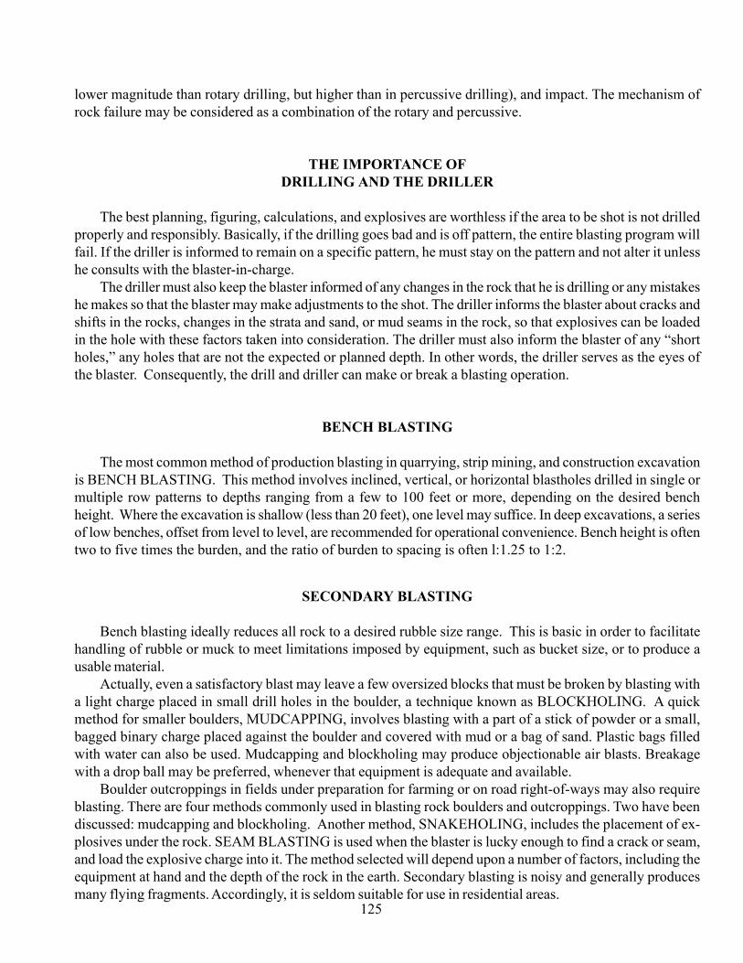
Due to the time required for an explosive to become effective and build up pressures in the borehole, itis necessary to subdrill past the desired grade. The distance to consider for overdrilling is dependent on therock formation and the velocity of the explosive to be used.
For best production results, the driller should be three to four hundred feet ahead of the blaster at alltimes. It is up to the blaster to keep his “breaking face” open by not losing any holes. The diagram belowshows the correct and incorrect drilling practices:
USE OF AMMONIUM NITRATE FUEL OIL IN THE UTILITY AND LIGHTCONSTRUCTION INDUSTRY
These industries normally use drilling equipment that does not lend itself to the use of ANFO (3 1/2"diameter holes or smaller). ANFO used in these diameters will not achieve velocities high enough to doan effective job of fracturing the rock formation. It is possible to overdrive the ANFO as explainedbefore, but this can be very expensive.
If the diameter of the borehole exceeds the diameter of the explosive by more than one-half inch,borehole coupling can be achieved very effectively by filling in the air space around the ANFO withstemming.
CAUTION: ANFO has more gas energy (heave) than any other explosive. This very often results inmore flyrock and less control of desired dimensions in tight shooting conditions.
(Figure 9-21) Good loading procedure for bagged ANFO(wet hole) 4 1/2" diameter or greater.
143
The driller's responsibility is to:A. Maintain exact distances between holes.B. Keep hole depth uniform.C. Keep holes vertical to one another.D. Notify blaster of changes in drilling, overburden, rock depth, lost holes, etc.E. Cover the drilled holes.
USED CONVEYOR BELTING BLASTING MATS
This mat consists of three parts:1. The center mat is without chains.2. The two outer mats have short pieces of chain bolted to them.3. The mat should be placed over the area to be protected in the following manner:

144
Note: This is an exceptionally good low density rock formation pattern.
Note: Maximum fragmentation of rock is achieved when holes are laid out andfired in a triangle. The converging shock waves from the configuration canoften allow the use of less explosives in each hole.
When adjusting all patterns to meet your needs, spread or close drill pat-terns in six-inch increments until desired results are achieved.
TRENCHING (TRACK DRILL)
24" ditch width, 0"-48"grade depth (drill holedepth = grade + 12")
24"-36" ditch width, 48" -144" grade depth (drill holedepth = grade + 18")
36-48" ditch width, 48"-144" grade depth (drill hole

145
DOUBLE PRIMING
Double priming should be considered when the solid rock in a borehole depth is eightfeet or more, or there is a mud or earth seam in a formation of four inches or more.
Allow for a minimum of 10 inches stemming below and above the mud seam beforeplacing the top charge.
The necessity of double priming will depend on the thickness and density of the rock, aswell as the continuity of the formation. In many formations, the heave energy will lift andfragment the upper layers of the formation without double priming.
This mat should always be used with a minimum of eight inches of overburden between the top of the rockand the blasting mat.
Note: When connecting the chain of the outer mats across the center mat, do not leave any slack in the chain.
(Figure 9-22) Double priming. Numbers indicate electric blasting cap delay period.

146
TRENCH SHOOTING (HAND-HELD ROCK DRILL)
12"-18" ditch width (drill hole depth = grade + 12") This type of shootinginvolves the use of small diameter explosives (1"-1 7/8" diameter).
18"-24" ditch width (drill hole depth = grade + 12")
When using a hand-held rock drill, it is best to drill no deeper than four feet at a time. Manpower efficiencydecreases, and drill steel hang-ups increase dramatically past this depth. It is more economical to drill the fourfeet, shoot, clean out, and drill again if greater depth is needed.
PIT SHOOTING
The breaking face is created at the bottom of the Diagram A by shooting thefirst two rows as a trench line is shot. The balance of the holes are delayed tomove toward the created breaking face one row at a time.
This diagram is for track drill, using a 2 1/2" drill bit, 3-foot spacing betweenholes, 2" diameter explosive, and 1-12 milliseconds delay periods.
The breaking face in Diagram B is created in the center line, moving towardthe bottom of the diagram with the sides folding into center on different de-lays.
This diagram is for track drill using 2 1/2" drill bit, 3-foot spacing betweenholes, 2" diameter explosive, and 1-12 milliseconds delay periods.
POLE HOLE SHOOTING
Drill a single hole two feet deep where the pole will be set. Use one stick of powder (1 1/4" x 8") with capinserted to shoot toward the bottom of the hole and clean out. Drill two holes 10 inches apart, two feet deep.Shoot and clean out. Repeat until desired depth is reached. Depending on the density of the rock, you may useany amount from one-half of a stick to a full stick in each hole.
A center hole is drilled, but not loaded, creating a breaking face in the pattern. This pattern is utilizedwhen using hand-held rock drills or track drills where rock formation demands are tough.
Diagram A
Diagram B

147
(Figure 9-24) Directional action of explosives.
(Figure 9-23) Pole hole shooting
(Figure 9-25) Single hole configuration in pole hole shooting.

148
(Figure 9-26) Boulder breaking. The blasting cap must always be pointed toward the intended direction of the shock energy.
Normally, one 1-pound explosive pouch is required per each cubic yard of rock to be blasted. Itis possible in many cases to reduce this amount if the blaster wants to take the time to “dobe” theexplosive.
This same principle can be applied to remove small outcroppings of rock in ditch lines, etc., withreasonable success. However, this method is not recommended in solid ledge rock because the shockwave exits but does not return, resulting in very little or no breakage. This method of breaking rock isextremely noisy and should not be done if blasting noise disturbs neighbors in the area where blastingis being considered.
BOULDER BREAKING It is possible to break rock with the shock energy of an explosive without drilling any
holes in the rock if the approximate size of the rock is known.Example: Assume that you need to break a 3-cubic-yard rock (boulder). By using three 1-pound explosive
pouches placed as in the following drawing, you can break the rock with the shock energy created by theexplosive, in most cases. Very little, if any, flyrock occurs when breaking rock in this manner (shock energy doesnot throw rock).
Normally, one 1-pound explosive pouch is required per each cubic yard of rock to be blasted. It is possiblein many cases to reduce this amount if the blaster wants to take the time to 'dobe' the explosive. This

149
Regardless of where the explosive is placed, if the blasting cap is pointed in the direction of the rock to beblasted, the shock energy in the explosive will be absorbed by the rock. Shock energy will not leave the rockthat it enters. If there is a crack in the rock, the shock energy will not exit the crack.
It is important that the explosive maintain intimate contact with the rock. This is the reason the one-poundpouch is in a flexible package, allowing the explosive to conform to blasting surface.
(Figure 9-27) Boulder breaking. The blasting cap must always be pointed toward the intendeddirection of the shock energy. At bottom are suggested powder stackings forvarious amounts of 1-pound explosive pouches that allow the greatestpenetration of shock energy to rock.
STUMP SHOOTING
The most important thing to remember about shooting stumps is that the explosive must be placedunder the stump. The prescribed method is to punch holes under the stump at an angle, toward the centerof the stump. The depth of these holes depends on the width of the stump. A 24- to 30-inch-deep holewill suffice for most stumps 5 inches to 18 inches in diameter. A stump 10 inches or more in diametermay require two or more holes. The powder used should be 1/2 pound to every 5 inches of diameter.
Example: A 15-inch-wide stump can usually be lifted out of the ground with 1 1/2 pounds of explo-sives.
In large diameter stump shooting (three feet or more), it is sometimes necessary to “spring” a hole,or punch it, as deep as possible toward the center of the stump. Place a 1/2 pound charge in the hole anddetonate. This usually results in blowing a cavity beneath the stump. Let the hole cool, then clean it outand place the amount of explosive required (using powder factor mentioned in previous paragraph). Fillthe cavity back in and detonate.
CONVERGING SHOCK WAVE BLASTING PRINCIPLEThis pouch layout can produce extreme pressures within the rock because the converging shock waves
meet in the center of the triangle, increasing shock wave intensity many times. This allows larger rocks to bebroken with less explosives. All caps should detonate at the same time. The triangle can be different sizes,but should form as close to a perfect triangle as possible. Sometimes it is best to separate the explosivecharge over the surface of a rock. Detonation should occur simultaneously in each of the charges, injecting theshock wave throughout the rock at the same time.

150
When shooting two or more holes, make sure that both holes go off at the same time. Electric blastingworks best.
Again, it is recommended that the stump is protected with a cover of some kind to prevent pieces ofrock or stump from flying into the air. Removal of live tree stumps may require more explosive than a treestump that has been dead for any length of time. An explosive with good heave energy is best for this typeof work. Binary explosives have more heave energy than dynamite.
HAZARD TREE FELLING WITH EXPLOSIVES
Felling hazard trees with explosives is often safer than felling with a power saw because personnelare at a safe distance from the tree when the danger is highest. General blasters and fireline explosives
(Figure 9-28) Separation of explosive charges over rock.
(Figure 9-29) Large diameter stump shooting with holes punched toward center of stump.

151
blasters can be certified by National Park Service blaster examiners to conduct hazard tree blasting. All hazardtrees must be assessed before they are felled. Extreme care is essential where trees are rotten, weak, on fire, orhave significant lean. Always approach a hazard tree away from the lean. When assessing a hazard tree to befelled, determine the following:
1. Is the tree green, dead, hollow, and/or rotten?A dead, hollow tree will require that explosives be spread across the face to avoid blowing a hole in the
center and leaving the tree standing. A live, solid green tree may take slightly more explosives concentrated inone location and shaped in a pyramid to develop an appropriate shock wave. Look for conks, broken tops,basal scars, cat faces, numerous downed limbs, etc., that may indicate rot. Also, look to see if numerous treesare down in an area. This may indicate a pocket of trees with rot.
2. Is the tree burning?Fire burning in a tree may indicate rot, which results in a weakened tree. If the tree is burning in the top, use
only water gel, emulsion, or PETN-based explosives or explosives approved for fireline explosive construction(FLE). If the tree is burning at the base, STOP! Do not use explosives if there is a probability that they will catchfire!
Explosives that are on fire must not be touched! Do not attempt to extinguish explosives that are on fire!Also, if the tree may fall across burn control lines, special precautions may need to be taken.
3. Determine the tree diameter where the explosives will be placed (generally at chest height).
4. Determine whether external or internal blasting methods should be used.
a. The term internal indicates that a hole will be drilled in the tree for the explosives charge (Figure 9-28).This method is not recommended for hollow or rotten trees or trees that are so hazardous that theactivity might trigger a fall.
(Figure 9-30) Large diameter stump shooting with holes punched toward center of stump.
b. The term external indicates that the explosives will be placed on the outside of the tree in one locationor by wrapping the tree with linear type fireline explosives. Wrapping is the least preferred method ofhazard tree blasting because the direction of the fall is left to chance. Also, not enough explosives willbe used when a large tree is single wrapped, which will leave the tree standing and weakened.

152
INTERNAL HAZARD TREE FELLING
Internal hazard tree blasting is often preferable to external because less explosive is needed and shockwave and noise are reduced. However, direction of fall is unpredictable and the tree must be disturbed to drilla hole for the explosives.
The formula used for internal hazard tree felling with explosives is:
W = D /250 (Metric Equivalent: W = D /3560)
W = Weight of the explosives in pounds(Metric Equivalent: kilograms)
D = Diameter of the tree in inches, where the explosives will be placed. (Metric Equivalent:centimeters).
Example: Tree Diameter = 24 inches (Metric Equivalent: 61 centimeters)2
W = (24 )/250 = 576/250 = 2.3 pounds(Metric Equivalent: (61 )/3560 = 1.04 kg)
When using explosives that are supplied in one-pound sticks, place three sticks (always round up). Usingexplosives supplied in 0.5 kg sticks, place two sticks. With packaged emulsions or water gels that can beextruded into the borehole, use two to three pounds (1kg).
Using a 1.25-inch linear water gel explosive (fireline), divide 2.3 pounds by 0.6 pounds per foot = 3.83 feet(1.17 meters). Round up and use 4 feet (1.2 meters) of linear FLE explosives.
Once the hazard tree has been loaded with explosives, the procedures for detonation are the same as forfireline explosives. Use exploding bridgewire detonators, the customary 500 feet (152 meters) of shot line fordistance requirements, and place appropriate guards. (See special considerations at the end of this section.)
EXTERNAL HAZARD TREE FELLING
External hazard tree felling is a preferred method because the blaster has a high degree of control overwhich way the tree will fall. However, air blast will be higher for this method than in the internal method, andit is often difficult to place large amounts of bulk explosives in one location on a tree. An exception is wherepackaged explosives can be removed or extruded from the container, shaped, and then stuck to the surface of thetree.
The formula used for external hazard tree blasting is:
W = D /40 (Metric equivalent: W = D /569)
W = Weight of explosives in pounds(Metric equivalent: kilograms)
D = Diameter of the tree in inches, where the explosives will be placed. (Metric Equivalent: centi-meters)
Example: Diameter of the tree is 24 inches (Metric equivalent: 62 centimeters)

153
W = (24 )/40 = 576/40 = 14.4 pounds(Metric equivalent: (61 )/569 = 6.54 kg)
When using explosives supplied in 1-pound sticks, place 15 sticks concentrated in one location (alwaysround up). Using explosives supplied in 0.5 kg sticks, place 13 sticks. When using explosives that can beextruded from the package, place 14.4 pounds (6.54 kg).
Using 1.25-inch linear water gel fireline (FLE) explosives at 0.6 pounds per foot, use 14.4/0.6 = 24 feet(7.3 meters) of linear fireline explosives concentrated in one location.
NOTE: If the tree is wrapped with the linear explosives (FLE), the quantity becomes n x (24/12) = 6.3 feet(2 meters). This is a significantly smaller quantity than predictably needed, and it would therefore require atleast six wraps to ensure that the tree would fall. Therefore, for every 4 inches (37 cm) in diameter, wrap thetree once with fireline (FLE) explosive.
SPECIAL CONSIDERATIONS
1. Place the detonator or det cord on the top of the pyramid of explosives to develop appropriate shockwaves to fell the tree.
2. Where bark is unusually thick or loose, it should be removed from the tree before placement of theexplosives. CAUTION: this may not be safe practice on some trees.
(Figure 9-31) Tree diameter and respective explosives loads.
3. Always place the explosives on the “direction of fall” side of the tree unless the danger warrantsotherwise. Never assume that a tree will fall in a given direction.
4. Assume that all blasts will produce flying debris.5. Always adhere to the 500-foot (152-meter) distance rule.6. Always use a detonation system that is not susceptible to the hazards of electromagnetic radiation
(EBWs or nonel).7. Use extreme care around hollow rotten trees. Spread explosives across the face of the tree to avoid
blowing a hole through the center, which could leave the tree standing and extremely dangerous to approach thesecond time.
8. When in doubt, use more explosives than the formulas indicate, especially when wrapping large treeswith linear fireline explosives.

154
9. Always follow the rules and practices given in the Guide for Using, Storing, and TransportingExplosives and Blasting Materials and on the instruction sheet in every box of explosives.
10. Take special precautions where burning trees may fall across burn control lines.
POST HOLE SHOOTING
Drill a single hole, 24" to 30" deep, large enough in which to fit the explosive. Place the cap in theexplosive charge where, when inserted in the hole, the cap points toward the bottom of the hole. In hardpanor seamy rock formations, usually one-half of a stick of a good binary explosive will accomplish the task. Insolid rock, one full stick is necessary.
(Figure 9-31) TPost hole shooting.
DRILLING HOLES
In rock formations, a hand-held rock drill is required. This equipment can be rented at most equipmentrental stores. In hardpan or hard-packed ground, a digging bar or hand auger will usually be the cheapestand best way to punch a hole.
In many cases, fences are built close to dwellings, roads, etc. It is always advisable to cover a shot withsome kind of material. Used conveyor belting, old bed springs, chain link fence, two feet of dirt, plywood,old tires, etc., make reasonably good blasting mats for this type of shooting.