Chapter 9 Following Instructions: Principles of Computer Operation.
55
Chapter 9 Following Instructions: Principles of Computer Operation
-
Upload
marianna-cameron -
Category
Documents
-
view
224 -
download
4
Transcript of Chapter 9 Following Instructions: Principles of Computer Operation.
Chapter 9
FollowingInstructions:Principles of Computer Operation

Copyright © 2006 Pearson Addison-Wesley. All rights reserved. 9-2
Instruction Execution Engines
• What computers can do– Deterministically perform or execute instructions to
process information
– The computer must have instructions to follow
• What computers can't do– Have no imagination or creativity
– Have no intuition
– Have no sense of irony, subtlety, proportion, decorum, or humor
– Are not vindictive or cruel
– Are not purposeful
– Have no free will

Copyright © 2006 Pearson Addison-Wesley. All rights reserved. 9-3
The Fetch/Execute Cycle
• A five-step cycle:
1. Instruction Fetch (IF)
2. Instruction Decode (ID)
3. Data Fetch (DF)
4. Instruction Execution (EX)
5. Result Return (RR)

Copyright © 2006 Pearson Addison-Wesley. All rights reserved. 9-4
Anatomy of a Computer
• Computers have five basic parts or subsystems
– Memory, control unit, arithmetic/logic unit (ALU), input unit, output unit
Copyright © 2006 Pearson Addison-Wesley. All rights reserved. 9-5
Memory
• Memory stores the program running and the data on which the program operates
• Properties of memory:
– Discrete locations. Each location consists of 1 byte
– Addresses. Every memory location has an address (whole numbers starting with zero)
– Values. Memory locations record or store values
– Finite capacity. Limited size—programmers must remember that the data may not "fit" in the memory location
Copyright © 2006 Pearson Addison-Wesley. All rights reserved. 9-6
Byte-Size Memory Location
• A commonly used diagram of computer memory represents the discrete locations as boxes.
• Address of location is displayed above the box.
• Value or contents of location is shown in the box.

Copyright © 2006 Pearson Addison-Wesley. All rights reserved. 9-7

Copyright © 2006 Pearson Addison-Wesley. All rights reserved. 9-8
Memory (cont'd)
• 1-byte memory locations can store one ASCII character, or a number less than 256
• Programmers use a sequence of memory locations together, ignoring the fact that they all have different addresses
– Blocks of four bytes are used as a unit so frequently that they are called memory "words"

Copyright © 2006 Pearson Addison-Wesley. All rights reserved. 9-9
Random Access Memory
• "Random access" means the computer can refer to the memory locations in any order
• Often measured in megabytes (MB)
• Large memory is preferable because there is more space for programs and data

Copyright © 2006 Pearson Addison-Wesley. All rights reserved. 9-10
Control Unit
• Hardware implementation of the Fetch/Execute Cycle
• Its circuitry fetches an instruction from memory and performs other operations of the cycle on it
– A typical instruction might have the form ADD 2000, 2080, 4000
– This instruction asks that the numbers stored in locations 2000 and 2080 be added together, and the result stored in location 4000
– Data Fetch step must get these two values and after they are added, Result Return step will store the answer in location 4000
Copyright © 2006 Pearson Addison-Wesley. All rights reserved. 9-11
Arithmetic/Logic Unit
• Performs the math
• Generally does the work during the Instruction Execute step of the Cycle
• A circuit in the ALU can add two number
• There are also circuits for multiplying, comparing, etc.
• Instructions that just transfer data usually don't use the ALU
• Value Fetch step of the Cycle gets the values that the ALU needs to work on (operand)
• When the ALU completes the operation, Return Result step moves the answer from the ALU to the memory address specified in the instruction
Copyright © 2006 Pearson Addison-Wesley. All rights reserved. 9-12
Input Unit and Output Unit
• The wires and circuits through which information moves into and out of a computer
• The peripherals: Connect to the computer input/output ports. They are not considered part of the computer, but specialized gadgets that encode or decode information between the computer and the physical world.

Copyright © 2006 Pearson Addison-Wesley. All rights reserved. 9-13
The Peripherals
• Keyboard encodes keystrokes we type into binary form for the computer
• Monitor decodes information from the computer's memory and displays it on a lighted, colored screen
• Disks and drives are used for both input and output—storage devices where the computer puts away information when it is not needed, and can retrieve from when it is needed again

Copyright © 2006 Pearson Addison-Wesley. All rights reserved. 9-14
A Device Driver for Every Peripheral
• "Dumb" devices provide basic physical translation to or from binary signals.
• Additional information from the computer is needed to make it operate intelligently.
• e.g., computer receives information that user typed shift and w at the same time. It converts to a capital W. The software that converts is called the device driver.

Copyright © 2006 Pearson Addison-Wesley. All rights reserved. 9-15
The Program Counter: The Pc's PC
• How does the computer determine which step to execute next?
• Address of the next instruction is stored in the control part of the computer. It is called the program counter (PC)
• Because instructions use 4 bytes of memory, the next instruction must be at PC + 4, 4 bytes further along in the sequence
• Computer adds four to the PC, so when the F/E Cycle gets back to Instruction Fetch step, the PC is "pointing at" the next instruction

Copyright © 2006 Pearson Addison-Wesley. All rights reserved. 9-16
Branch and Jump Instructions
• The instruction may include an address to go to next. This changes the PC, so instead of going to PC +4 automatically, the computer "jumps" or "branches" to the specified location.

Copyright © 2006 Pearson Addison-Wesley. All rights reserved. 9-17
Instruction Interpretation
• Process of executing a program– Computer is interpreting our commands,
but in its own language
• Before the F/E Cycle begins, some of the memory locations and the PC are visible in the control unit

Copyright © 2006 Pearson Addison-Wesley. All rights reserved. 9-18
Copyright © 2006 Pearson Addison-Wesley. All rights reserved. 9-19
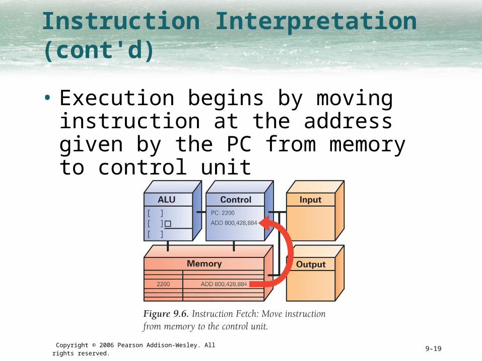
Instruction Interpretation (cont'd)
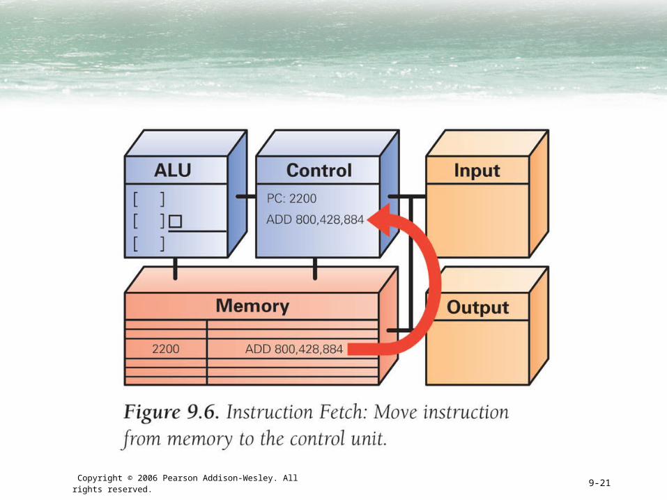
• Execution begins by moving instruction at the address given by the PC from memory to control unit

Copyright © 2006 Pearson Addison-Wesley. All rights reserved. 9-20
Instruction Interpretation (cont'd)
• Bits of instruction are placed into the decoder circuit of the CU
• Once instruction is fetched, the PC can be readied for fetching the next instruction
Copyright © 2006 Pearson Addison-Wesley. All rights reserved. 9-21

Copyright © 2006 Pearson Addison-Wesley. All rights reserved. 9-22
Instruction Interpretation (cont'd)
• In Instruction Decode step, ALU is set up for the operation
• Decoder will find the memory address of the instruction's data (source operands)– Most instructions operate on two data values stored in memory
(like ADD), so most instructions have addresses for two source operands
– These addresses are passed to the circuit that fetches them from memory during the next step, Data Fetch
• Decoder finds destination address for the Result Return step, and places it in RR circuit
• Decoder determines what operation the ALU will perform, and sets it up appropriately

Copyright © 2006 Pearson Addison-Wesley. All rights reserved. 9-23

Copyright © 2006 Pearson Addison-Wesley. All rights reserved. 9-24
Instruction Interpretation (cont'd)
• Instruction Execution: The actual computation is performed. For ADD instruction, the addition circuit adds the two source operands together to produce their sum

Copyright © 2006 Pearson Addison-Wesley. All rights reserved. 9-25
Copyright © 2006 Pearson Addison-Wesley. All rights reserved. 9-26
Instruction Interpretation (cont'd)
• Result Return: result of execution is returned to the memory location specified by the destination address.
• Once the result is returned, the cycle begins again.

Copyright © 2006 Pearson Addison-Wesley. All rights reserved. 9-27

Copyright © 2006 Pearson Addison-Wesley. All rights reserved. 9-28
Many, Many Simple Operations
• Computers can only perform about 100 different instructions– About 20 different kinds of operations (different
instructions are needed for adding bytes, words, decimal numbers, etc.)
• Everything computers do must be reduced to some combination of these primitive, hardwired instructions

Copyright © 2006 Pearson Addison-Wesley. All rights reserved. 9-29
Examples of Other Instructions
• Besides ADD, MULT (multiply) and DIV (divide), other instructions include:
– Shift the bits of a word to the left or right, filling the emptied places with zeros and throwing away bits that fall off the end
– Compute logical AND (test if pairs of bits are both true, and logical OR, which tests if at least one of two bits is true
– Test if a bit is zero or non-zero, and jump to new set of instructions based on outcome
– Move information around in memory
– Sense signals from input/output devices
Copyright © 2006 Pearson Addison-Wesley. All rights reserved. 9-30
Cycling the F/E Cycle
• Computers get their impressive capabilities by executing many of these simple instructions per second
• The Computer Clock: Determines rate of F/E Cycle
– Measured in megahertz, or millions of cycles per second

Copyright © 2006 Pearson Addison-Wesley. All rights reserved. 9-31

Copyright © 2006 Pearson Addison-Wesley. All rights reserved. 9-32
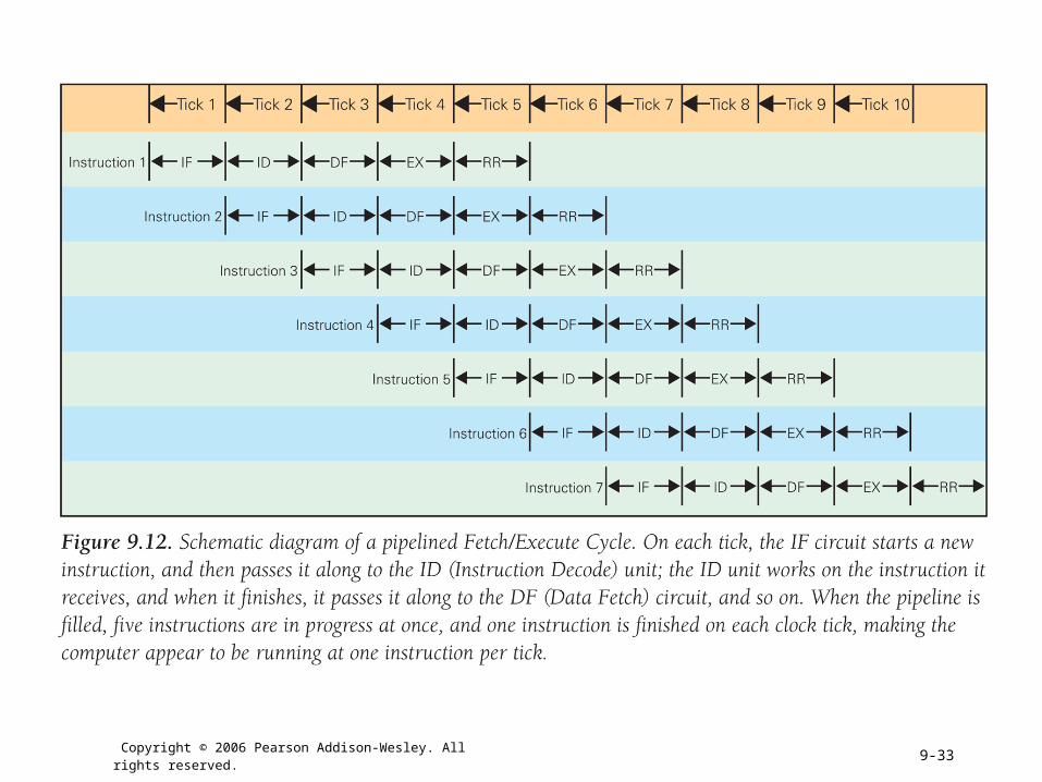
How Important is Clock Speed?
• Modern computers try to start an instruction on each clock tick
• Pass off finishing instruction to other circuitry (pipelining)– Five instructions can be in process at the
same time
• Does a 1 GHz clock really execute a billion instructions per second?– Not a precise measurement. Computer may not be able to
start an instruction on each tick, but may sometimes be able to start more than one instruction at a time
Copyright © 2006 Pearson Addison-Wesley. All rights reserved. 9-33

Copyright © 2006 Pearson Addison-Wesley. All rights reserved. 9-34
Software
• A computer's view of software – Sees binary object file, a long sequence of
4-byte words
• Assembly language– Alternative form of machine language using letters
and normal numbers so people can understand it
– Computer scans assemble code, as it encounters words it looks them up in a table to convert to binary, converts numbers to binary, then assembles the binary pieces into an instruction
Copyright © 2006 Pearson Addison-Wesley. All rights reserved. 9-35
Software (cont'd)
• High-level programming languages– Most modern software is written in high-level
notation, which is then compiled (translated) into assembly language, which is then assembled into binary
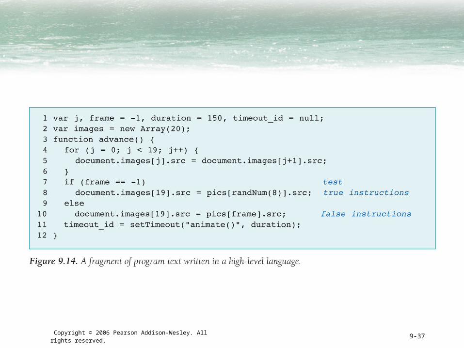
– Have special statement forms to help programmers give complicated instructions
• Example: Three-part if statement
– Yes/no question to test
– Instructions to operate if test is true
– Instructions to operate if test is false

Copyright © 2006 Pearson Addison-Wesley. All rights reserved. 9-36
Copyright © 2006 Pearson Addison-Wesley. All rights reserved. 9-37
Copyright © 2006 Pearson Addison-Wesley. All rights reserved. 9-38
Operating Systems
• Basic operations that are necessary for the effective use of computer, but are not built into the hardware
• Three most widely used Operating Systems:– Microsoft Windows
– Apple's MacX
– Unix
• OS performs booting, memory management, device management, Internet connection, file management
Copyright © 2006 Pearson Addison-Wesley. All rights reserved. 9-39
Programming
• Programmers build on previously developed software to make their jobs easier
• Example: GUI Software– Frame around window, slider bars,
buttons, pointers, etc. are packaged for programmers and given with OS

Copyright © 2006 Pearson Addison-Wesley. All rights reserved. 9-40
Integrated Circuits
• Miniaturization:– Clock speeds are so high bc. processor
chips are so tiny (electrical signals can travel about 1 foot in a nanosecond)
Copyright © 2006 Pearson Addison-Wesley. All rights reserved. 9-41
Integrated Circuits
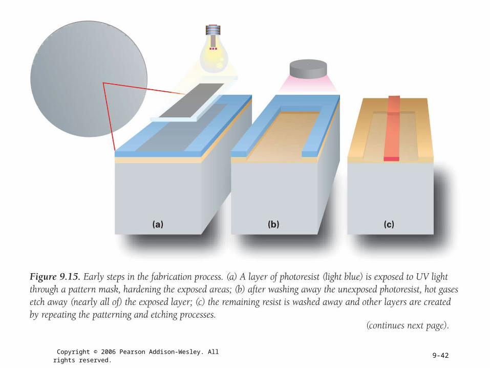
• Photolithography
– Printing process. Instead of hand-wiring circuits together, photograph what is wanted and etch away the spaces
– Regardless of how complicated the wiring, cost and amount of work are the same
Copyright © 2006 Pearson Addison-Wesley. All rights reserved. 9-42
Copyright © 2006 Pearson Addison-Wesley. All rights reserved. 9-43

Copyright © 2006 Pearson Addison-Wesley. All rights reserved. 9-44
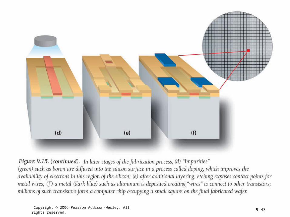
How Semi-conductor Technology Works
• Integration:– Active components and the wires that connect
them are all made together of similar materials in a single process
– Saves space and produces monolithic part for the whole system, which is more reliable
• Silicon is a semi-conductor—sometimes it conducts electricity, sometimes not– Ability to control when semi-conductor conducts is
the main tool in computer construction
Copyright © 2006 Pearson Addison-Wesley. All rights reserved. 9-45
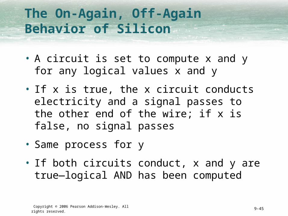
The On-Again, Off-Again Behavior of Silicon
• A circuit is set to compute x and y for any logical values x and y
• If x is true, the x circuit conducts electricity and a signal passes to the other end of the wire; if x is false, no signal passes
• Same process for y
• If both circuits conduct, x and y are true—logical AND has been computed

Copyright © 2006 Pearson Addison-Wesley. All rights reserved. 9-46
The Field Effect
• Controls the conductivity of the semiconductor
• Objects can become charged positively or negatively– Like charges repel each other, but opposites
attract. This effect is called the field effect.

Copyright © 2006 Pearson Addison-Wesley. All rights reserved. 9-47
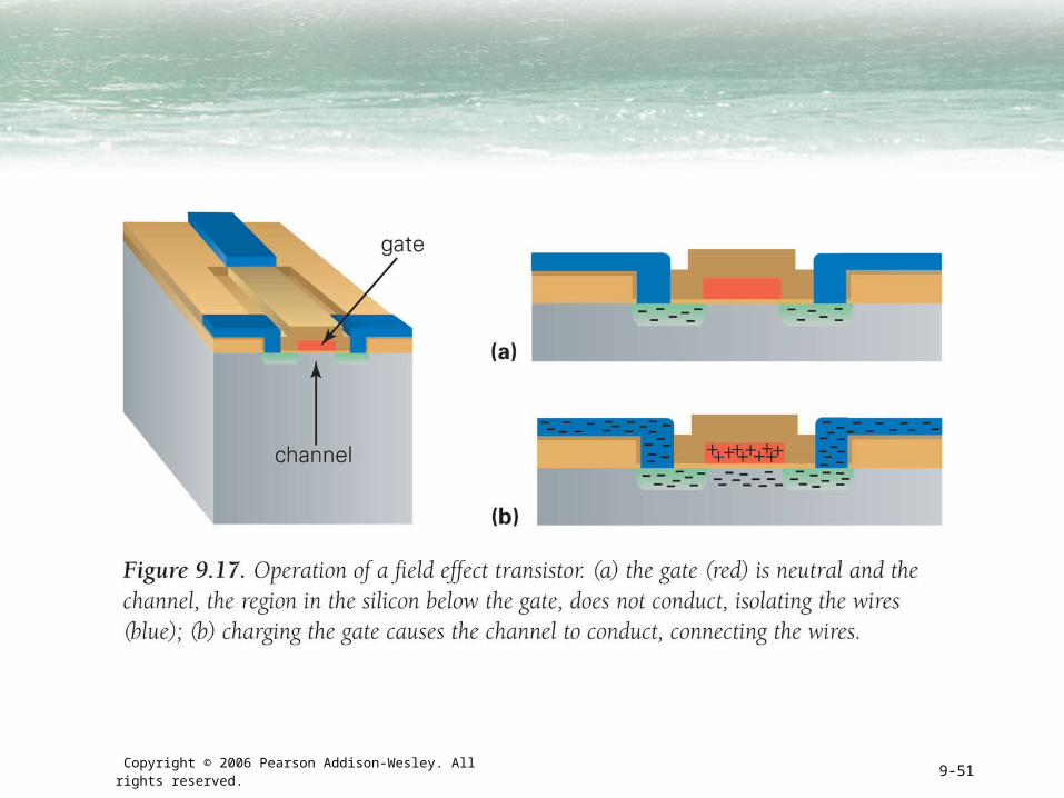
The Field Effect (cont'd)
• The gab between two wires is treated to improve its conducting and non-conducting properties
• This is called a channel (path for electricity to travel between the two wires)
• An insulator covers the channel
• A wire called the gate passes over the insulator
• The gate is separated from the channel by the insulator—does not make contact with the wires or the channel
• Electricity is not conducted between the two wires unless the channel is conducting
Copyright © 2006 Pearson Addison-Wesley. All rights reserved. 9-48
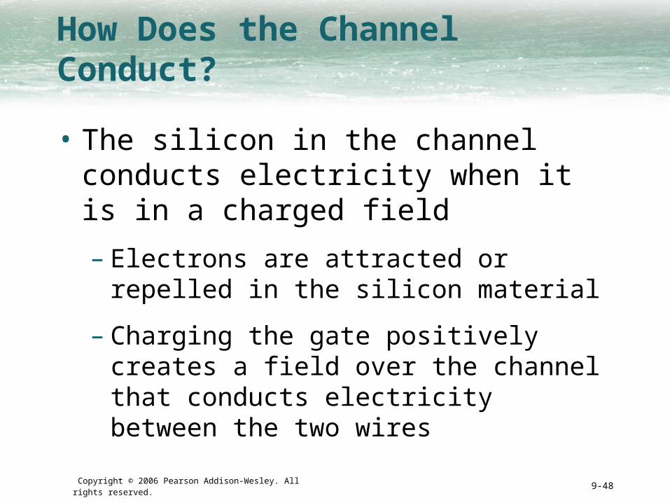
How Does the Channel Conduct?
• The silicon in the channel conducts electricity when it is in a charged field
– Electrons are attracted or repelled in the silicon material
– Charging the gate positively creates a field over the channel that conducts electricity between the two wires

Copyright © 2006 Pearson Addison-Wesley. All rights reserved. 9-49
Transistors
• A connector between two wires that can be controlled to allow charge to flow between the two wires, or not
• We have described a MOS transistor (metal, oxide, semiconductor)

Copyright © 2006 Pearson Addison-Wesley. All rights reserved. 9-50
Copyright © 2006 Pearson Addison-Wesley. All rights reserved. 9-51
Copyright © 2006 Pearson Addison-Wesley. All rights reserved. 9-52
Combining the Ideas
• Put all above ideas together:
– Start with information processing task
– Task is performed by application, implemented as part of a large program in a high-level language like C or Java
– Program performs specific operations; standard operations like print or save are done by OS
– Program's commands are compiled into assembly language instructions
– Assembly instructions are translated into binary code
– Binary instructions are stored on hard disk
– Application instructions move into RAM
Copyright © 2006 Pearson Addison-Wesley. All rights reserved. 9-53
Combining the Ideas (cont'd)
– Fetch/Execute Cycle executes the instructions
– All the computer's instructions are performed by the ALU circuits, using the transistor model previously described

Copyright © 2006 Pearson Addison-Wesley. All rights reserved. 9-54

Copyright © 2006 Pearson Addison-Wesley. All rights reserved. 9-55