Chapter 82 (English measure) - Indianain.gov/indot/design_manual/files/Ch82_2013.pdf · 82-1.02...
52
INDIANA DEPARTMENT OF TRANSPORTATION—2013 DESIGN MANUAL CHAPTER 82 Traffic-Control-Plan Design Design Memorandum Revision Date Sections Affected 13-01 Jan. 2013 Figure 82-6B, Figure 82-6C 13-03 Feb. 2013 82-6.03 NOTE: This chapter is currently being re-written and its content will be included in Chapter 503 in the future.
Transcript of Chapter 82 (English measure) - Indianain.gov/indot/design_manual/files/Ch82_2013.pdf · 82-1.02...

INDIANA DEPARTMENT OF TRANSPORTATION—2013 DESIGN MANUAL
CHAPTER 82
Traffic-Control-Plan Design
Design Memorandum
Revision Date
Sections Affected
13-01 Jan. 2013 Figure 82-6B, Figure 82-6C 13-03 Feb. 2013 82-6.03
NOTE: This chapter is currently being re-written and its content will be included in Chapter 503 in the future.

Page 2 2013 Indiana Design Manual, Ch. 82
TABLE OF CONTENTS
LIST OF FIGURES ......................................................................................................................... 3
82-1.0 PRELIMINARY ENGINEERING ..................................................................................... 4
82-1.01 Responsibilities............................................................................................................. 4
82-1.02 District Input ................................................................................................................. 5
82-1.03 Engineer’s Report ......................................................................................................... 5
82-2.0 TRAFFIC-CONTROL-PLAN DEVELOPMENT .............................................................. 7
82-2.01 Responsibilities............................................................................................................. 7
82-2.02 Plan Development ........................................................................................................ 8
82-2.03 Traffic-Control Plan Content ...................................................................................... 10
82-2.04 Design Considerations ................................................................................................ 12
82-2.04(01) Engineering ...................................................................................................... 12
82-2.04(02) Constructability ................................................................................................ 13
82-2.04(03) Construction Design ......................................................................................... 13
82-2.04(04) Economic or Business Impact .......................................................................... 14
82-2.04(05) Pedestrians and Bicyclists ................................................................................ 14
82-3.0 GEOMETRIC DESIGN ................................................................................................... 15
82-3.01 Construction-Zone Design Speed ............................................................................... 15
82-3.02 Lane or Shoulder Width ............................................................................................. 16
82-3.03 Transition Taper Rate ................................................................................................. 17
82-3.04 Sight Distance ............................................................................................................. 17
82-3.05 Horizontal Curvature .................................................................................................. 18
82-3.06 Vertical Curvature ...................................................................................................... 19
82-3.07 Cut or Fill Slope ......................................................................................................... 19
82-3.08 Maximum Grade ......................................................................................................... 19
82-3.09 Through-Lane Cross Slope ......................................................................................... 19
82-3.10 Vertical Clearances ..................................................................................................... 20
82-4.0 ROADSIDE SAFETY ...................................................................................................... 20
82-4.01 Positive Protection ...................................................................................................... 20
82-4.02 Appurtenance Type ..................................................................................................... 21
82-4.02(01) Guardrail .......................................................................................................... 22
82-4.02(02) Temporary Traffic Barrier (TTB) ..................................................................... 22
82-4.02(03) End Treatment or Impact Attenuator ............................................................... 24
82-4.03 Design/Layout ............................................................................................................. 25
82-4.04 Pavement Edge Dropoff on Multilane Divided Highway .......................................... 25
82-5.0 HIGHWAY CAPACITY .................................................................................................. 27

2013 Indiana Design Manual, Ch. 82 Page 3
82-5.01 Traffic-Capacity Analysis .......................................................................................... 27 82-5.02 Queuing Analysis ....................................................................................................... 27
82-6.0 APPLICATIONS .............................................................................................................. 28 82-6.01 Lane or Shoulder Closure ........................................................................................... 28 82-6.02 Two-Way Traffic on a Divided Highway .................................................................. 30 82-6.03 Interstate Highways Congestion Policy [Rev. Feb. 2012] ......................................... 32 82-6.04 Runaround or Detour .................................................................................................. 32
FIGURES ...................................................................................................................................... 35 LIST OF FIGURES Figure Title 82-2A Participants During Traffic Control Plan Development 82-2B Editable Traffic Maintenance Memorandum to District 82-3A Minimum Radii for Horizontal Curves (Construction Zones) 82-3B K-Values for Sag Vertical Curves (Comfort Criteria in Construction Zones) 82-4A Flare Rates for Temporary Concrete Median Barrier (Construction Zones) 82-4B Clear Zone Distances (ft) (Construction Projects) 82-6A Lane Closures on Bridges 82-6B Interstate Lane Closure Policy – Statewide [Del. Feb. 2013] 82-6C Interstate Lane Closure Policy – Selected Urban Areas [Del. Feb. 2013] 82-7A Editable Traffic Control Plans Checklist

Page 4 2013 Indiana Design Manual, Ch. 82
CHAPTER 82
TRAFFIC-CONTROL-PLAN DESIGN
To some extent, highway construction disrupts the normal flow of traffic and poses safety hazards to
motorists, bicyclists, pedestrians and workers. Therefore, to alleviate potential operational and safety
problems, INDOT requires that work-zone traffic control be considered on each highway
construction project. The work-zone traffic-control plan may range in scope from very detailed
plans, incorporation of unique or recurring special provisions, or to merely referencing the INDOT
Standard Drawings, Standard Specifications, or Manual on Uniform Traffic Control Devices
(MUTCD). This Chapter provides the necessary information to develop a well-conceived work-zone
traffic-control plan that minimizes the adverse effects of traffic disruption and hazards.
82-1.0 PRELIMINARY ENGINEERING
82-1.01 Responsibilities
The Office of Environmental Services’ Environmental Policy Team is responsible for initially
addressing work-zone traffic control. This information is to be included in the Engineer’s Report. In
determining the initial work-zone traffic control, the Environmental Policy Team will perform the
following:
1. collect all necessary data (e.g. traffic counts, accident history, roadway geometrics, proposed
development, operating speeds);
2. coordinate planning and scoping meetings with the applicable participants (e.g., designer,
Office of Traffic Engineering, district Office of Design, Highway Operations Division, local
officials);
3. conduct analyses (e.g., capacity analyses, traffic impact studies, safety studies, queuing
analysis);
4. review design alternates;
5. review traffic-control alternates (e.g., detour, crossovers, runaround, lane closure). The
preferred plan will be incorporated into the Report;

2013 Indiana Design Manual, Ch. 82 Page 5
6. estimate the construction cost and economic impact of various options and improvements;
7. coordinate funding and timing with other projects within the corridor; and
8. if required, form a transportation-management-plan team and include the team’s
recommendations in the Report. Chapter 81 provides information on the development of a
TMP.
82-1.02 District Input
During the development of the Engineer’s Report, the Environmental Policy Team will obtain the
following information from the district.
1. The district’s concurrence in the selected traffic-control alternate;
2. detour-route location and additional travel distance;
3. traffic projections anticipated to use detour;
4. anticipated delays to fire, police, emergency-medical, or postal service;
5. number of school buses using facility (additional delay and distance); and
6. local roads which may be used for official or unofficial detour.
82-1.03 Engineer’s Report
The Environmental Policy Team will be responsible for incorporating the proposed work-zone traffic
control plan in the Engineer’s Report and ensuring that the following have been considered.
1. Traffic-Control Alternates. The Report will address the work-zone traffic-control
information as follows:
a. Applicability of INDOT Standard Drawings;
b. alternate traffic-control strategies;
c. alternate detour types and locations;
d. construction scheduling and phasing requirements;
e. alternate geometric design features;
f. estimated costs for alternate traffic-control strategies; and
g. special requirements of the work-zone traffic control.

Page 6 2013 Indiana Design Manual, Ch. 82
2. Construction Operation Selection. The construction applications which may be considered
are as follows:
a. work beyond the shoulder;
b. shoulder work and partial lane closure;
c. lane closure for a 2-lane highway;
d. single-lane closure for a 4-lane highway;
e. two-way traffic on a divided highway;
f. work within or near an intersection;
g. offset alignments; and
h. official or local detour (e.g., runaround, crossovers).
Chapter 81 provides additional guidance for determining which of these construction
applications may be appropriate.
3. Detour Location. The use of a detour (e.g., runaround, crossovers, alternate route) should be
determined on a project-by-project basis. The detour location should be in accordance with
the following:
a. minimize impacts to adjacent developments (e.g., site access);
b. minimize the magnitude and cost of utility relocations;
c. minimize environmental impacts; and
d. be offset a sufficient distance so that it will not interfere with construction.
The Department may be required to repair local highways that may be damaged while being
used as unofficial detour routes. See the INDOT Detour Policy for additional information.
Investigations, details, and agreements with local officials may be required in subsequent
phases.
4. Community Impact. The Report should address the impacts on neighborhoods, parks,
schools, businesses, etc. A detour can significantly increase traffic through a community
such that local traffic can no longer use the detour route. The Report should also address
how the work-zone traffic control will affect fire, ambulance, police, and school-bus routes.
5. Interest Groups. The Report should address the concerns of local governments, agencies,
public officials, or special interest groups (e.g., homeowner associations). If reasonable,
changes should be made to the work-zone traffic control to address their concerns. Working
with local officials and organizations early in project development can significantly reduce
opposition to, or create support for, a project by addressing local concerns.

2013 Indiana Design Manual, Ch. 82 Page 7
6. Transportation-Management Plan. Where a project does not warrant the development of a
Transportation Management Plan (TMP), the Environmental Policy Team should still review
Chapter 81 for applicable guidelines and criteria that should be discussed during this phase.
The conclusion of this phase should result in a reasonable traffic-control strategy for the
project.
82-2.0 TRAFFIC-CONTROL-PLAN DEVELOPMENT
82-2.01 Responsibilities
It is the designer’s responsibility to ensure that an adequate traffic-control plan (TCP) is developed.
If the traffic-control requirements are not entirely included in the INDOT Standard Drawings or
Standard Specifications, the designer should prepare a TCP that will adequately address all required
non-standard traffic-control work for the project. The designer will be responsible for the following.
1. reviewing the information in the Engineer’s Report or, if not available, contacting the
appropriate entity or agency (e.g., traffic-design, FHWA) to obtain the necessary information;
2. evaluating the proposed design alternates (e.g., detour, crossovers, runaround, lane closure);
see Chapter 81;
3. developing the geometric design for a specially-constructed detour (e.g., crossovers,
runaround, offset alignment); see Section 82-3.0;
4. addressing the roadside-safety concerns within the construction zone (e.g., construction clear
zone, temporary concrete barrier); see Section 82-4.0;
5. selecting and locating the required traffic control devices (e.g., pavement markings,
barricades, signs); see Chapter 83;
6. developing and evaluating alternate construction sequences;
7. performing the necessary capacity and queuing analyses, if not already provided;
8. making a written request to the Office of Pavement Engineering regarding use of a shoulder
or a portion of it for traffic maintenance. A copy of the request should be sent to the project
manager. The request should include the construction-year AADT, percent trucks of AADT,
and the approximate duration of traffic’s shoulder use;

Page 8 2013 Indiana Design Manual, Ch. 82
9. ensuring that the proposed traffic-control plan is discussed and reviewed during the
Preliminary Field Check; and
10. coordinating with public-information officials to inform the public of proposed road closure,
detour route, etc.
82-2.02 Plan Development
The TCP should be developed through the phases described below before it can be incorporated into
the contract and approved for letting. The following describes the development of the TCP at each
project phase.
1. Engineer’s Report. The Environmental Policy Team will be responsible for determining the
initial work-zone traffic control strategies to be used on the project. These should be shown
in the Engineer’s Report. If changes are made to the recommendations in the Report, the
designer should notify the Environmental Policy Team of these changes.
2. Structure Type and Size (Bridge-Replacement Project) or Grade Review (Sight-Distance
Improvement or Small Structure Replacement. At this plan development stage, the designer
is responsible for contacting the appropriate district to obtain its input regarding traffic
maintenance. Figure 82-2B is a blank memorandum copy which the designer should
download, fill in the project information blanks, then transmit to the district. An editable
version of this form may also be found on the Department’s website at
www.in.gov/dot/div/contracts/design/dmforms/. District input should be solicited if a TCP is
specified in the Engineer’s Report. The district should provide the requested information to
the designer.
3. Preliminary Field Check. During the Preliminary Field Check, review the proposed traffic-
control strategy against actual and anticipated field conditions and be prepared to perform the
following tasks.
a. drive the local detour;
b. determine the environmental effects of a crossover or runaround;
c. estimate the extent and cost of property damage caused by a crossover or runaround,
including additional right-of-way requirements and costs;

2013 Indiana Design Manual, Ch. 82 Page 9
d. determine the feasibility of maintaining traffic on the facility (e.g., roadway, bridge)
while work is in progress;
e. evaluate the need for scheduling work activities to avoid traffic delays during peak
commute hours or local events;
f. determine the effects on project constructability; and
g. review the physical and operational elements of the TCP with other projects in the
area to ensure that there are no conflicts with the proposed TCP.
At the conclusion of this phase, the preliminary geometric design, safety, and capacity
analyses should be completed, and suggested plan modifications evaluated and reviewed.
The designer should determine the proposed location of all traffic-control elements and
special design elements (e.g., runaround, crossovers) and should establish the proposed
construction phasing. The designer should contact the district for its input, even if the
proposed TCP is recommended in the Engineer’s Report.
4. Hearing. The plan and profile, cross-sections, construction schedule and phasing, and impact
reports should be completed at this stage. Begin preparation of the required special
provisions and the permit process. Prepare an estimate of the time required to re-open the
facility (e.g., roadway, bridge) to traffic after construction starts.
5. Final Field Check. Review all issues emerging from the hearing stage and complete
subsequent plan modifications. Review the project’s physical and operational elements of
the TCP with other projects in the area to ensure that there are no conflicts with the proposed
TCP. Examples include detouring traffic onto a local road which is scheduled for
reconstruction during the same time period, or closing a highly-traveled highway during
special events or seasons. Coordinate with the Office of Communications so that they can
begin to inform the public of road closures or alternate detour routes.
6. District Construction Engineer Review. After design approval, the designer should submit
the proposed TCP to the district construction engineer. The district construction engineer
will provide written comments or concurrence regarding the proposed TCP to the designer,
with a copy to the appropriate Production Management Division office manager. The office
manager will provide written comments or concurrence regarding the proposed TCP to the
designer. If necessary, the designer will revise the proposed TCP until both district
construction engineer and office manager concur.

Page 10 2013 Indiana Design Manual, Ch. 82
7. Final Plans Review. Determine and check all quantity estimates. Complete the detail
drawings and include all relevant special provisions in the contract documents. Do not show
unofficial detour routes in the plans or special provisions.
The Department requires a coordinated team effort to develop and successfully implement a TCP.
Figure 82-2A lists the participants involved in each phase of its development.
82-2.03 Traffic-Control Plan Content
The type and size of a project greatly impacts the amount of information required in the TCP. For
example, for a traffic-signs project, the TCP may only be a listing of the appropriate INDOT
Standard Drawings. However, for a freeway reconstruction project, the TCP may include full-size
drawings, special details, special provisions, special task forces, etc. The TCP content will be
determined on a project-by-project basis. The TCP may include the following.
1. Construction Plan Sheets. A reconstruction project will require detailed plans for
accommodating traffic at each construction stage (e.g., specially-built detour, crossovers,
staged construction). These plans may include geometric layout details, positive-protection
strategies, the traffic-control devices, etc. A smaller project (i.e., partial 3R, traffic signs,
signals, or a spot improvement) will rarely require this level of detail. Chapters 14 and 15
provide the Department’s plans-preparation criteria (e.g., sheet sizes, scales, line weights,
CADD symbols) which are also applicable to a TCP. The INDOT Typical Plan Sheets
document provides traffic-maintenance detail sheet examples.
A traffic-maintenance plan that requires at least one shoulder to carry traffic on a temporary
basis during construction should include information regarding shoulder-corrugation
installation requirements. A note should be included that reads, ―Corrugations shall not be
milled into the _____ shoulder between Sta. _____ and Sta. _____ until after traffic is no
longer temporarily using the shoulder.‖
2. Special Provisions. Special provisions are used to explain special procedures, materials, or
equipment used in the TCP that are not addressed in the INDOT Standard Specifications.
The TCP may only consist of special provisions. Prior to developing a new special
provision, the designer should first ensure that its requirements do not already appear in the
INDOT Standard Specifications or recurring special provisions. Chapter 19 provides
information on the requirements for preparing a special provision.
3. Traffic-Control Devices. Include a complete listing of the traffic-control devices required to
direct traffic through the work zone in the TCP. This may include the number of drums,

2013 Indiana Design Manual, Ch. 82 Page 11
barricades, cones, signs, temporary pavement markings, warning lights, flashing-arrow signs
or other devices required to implement the construction. Chapter 17 provides the
Department’s criteria for determining plan quantities.
4. Construction Sequence and Time. The TCP should include a proposed construction
sequence.
5. Work Schedule. A special provision should identify restricted work schedules which the
contractor will be required to follow (e.g., no construction work during specified hours or
days).
6. Telephone Numbers. A special provision should require the contractor to provide names and
telephone numbers of the contractor’s superintendent and one other responsible employee.
7. Permits. For restricted-lane width, the district Office of Construction will be responsible for
coordinating with the Planning Division’s Office of Roadway Safety and Mobility after the
contract is let to obtain the necessary permits to allow oversize vehicles through the work
zone.
8. Agreement or Legal Release. An agreement or legal release may be required before INDOT
can use a local facility as a detour route. The designer should initiate this process early in the
design of the work-zone traffic control.
9. Media. The designer should inform the Office of Communications as to when and where
there will be a major road or ramp closure or detour.
10. Pedestrians and Bicyclists. The TCP should address the safe accommodation of pedestrians
and bicyclists through the work area. Construction phasing may need to be scheduled around
non-peak pedestrian-traffic times.
11. Local Businesses and Residents. Maintain at least one reasonable access to each site of
business establishment or residency. The designer should also ensure that these entities are
kept informed of planned street, ramp or driveway closures.
12. Emergency Vehicles. The TCP should address the safe and efficient accommodation of
emergency vehicles through the construction area.
13. Checklist. Section 82-7.0 provides a checklist which should be reviewed to ensure that all
applicable work-zone traffic-control elements have been addressed in the TCP.

Page 12 2013 Indiana Design Manual, Ch. 82
82-2.04 Design Considerations
The objective of the TCP is to provide an implementation strategy that will minimize the adverse
effects of traffic disruption on motorists, pedestrians, bicyclists, or workers. Therefore, the designer
should consider the following design considerations when developing the TCP. For a more in-depth
analysis of these elements, the designer should review Chapter 81.
82-2.04(01) Engineering
The designer should consider the following engineering elements in developing the TCP.
1. Geometrics. The TCP should provide adequate facilities for a motorist to safely maneuver
through the construction area, day or night. The design should avoid frequent and abrupt
changes in roadway geometrics, such as lane narrowing, a lane drop, or a transition which
requires a rapid maneuver. Section 82-3.0 provides geometric design criteria for a
construction zone.
2. Roadside Safety. Motorist, pedestrian, bicyclist, and worker safety is a priority element of a
TCP and should be an integral part of each phase of the construction project (i.e., planning,
design, and construction). Section 82-4.0 addresses the roadside-safety issues which are
encountered during construction.
3. Highway Capacity. The TCP should, where practical, provide the capacity necessary to
maintain an acceptable level-of-service for the traveling public. This may require converting
a shoulder to a travel lane, eliminating on-street parking, constructing a temporary lane,
opening additional lanes during peak traffic-volume periods, or expanding public
transportation. Section 82-5.0 provides further information on highway-capacity issues.
4. Traffic-Control Devices. Traffic-control devices should be included in the TCP to safely
direct vehicles through or around the construction zone. Chapter 83 provides guidance on
the selection and location of traffic-control devices.
5. Overhead Lighting. The design should maintain existing overhead lighting and consider the
need for supplemental roadway lighting at a potentially hazardous site within the work area.
Chapter 83 discusses the use of construction-zone lighting.

2013 Indiana Design Manual, Ch. 82 Page 13
82-2.04(02) Constructability
The designer should evaluate the construction sequence to identify safety, operational, or logistical
problems and to facilitate the timely completion of the project. Some of the elements which should
be evaluated include the following:
1. the maneuverability of traffic through horizontal or vertical alignments during all
construction phases;
2. the separation of opposing traffic, workers, equipment, or other hazards;
3. the work area which will be used for equipment maneuverability; and
4. the access points to work sites or material-storage sites.
** PRACTICE POINTER **
Adequate working space between the traffic and the work area
should be provided. This applies especially where construction is
phased or if the project includes a temporary runaround.
82-2.04(03) Construction Design
Available construction options that may improve the TCP include the following:
1. the use of special materials (e.g., quick-curing concrete that can support vehicular loads
within hours after pouring);
2. the use of special designs (e.g., using a precast box structure instead of a bridge or cast-in-
place box structure);
3. scheduling requirements which will reduce traffic disruptions (e.g., working at night and
during off-peak traffic-volume hours);
4. project phasing which will allow traffic to use the facility prior to project completion; or

Page 14 2013 Indiana Design Manual, Ch. 82
5. contractor cost incentives/disincentive for early or late completion of construction for a
facility with a high AADT. For a project with FHWA oversight, a contractor incentive is
subject to approval by the FHWA.
Chapter 81 provides additional information on construction alternates.
82-2.04(04) Economic or Business Impact
The designer should consider the economic impacts a TCP may have on road users, adjacent
businesses, or residential developments. The designer should consider the following:
1. vehicular travel time;
2. fuel consumption;
3. vehicular wear;
4. air pollution;
5. access to residential developments;
6. patron access to businesses (e.g., restaurants, gas stations, stores);
7. employee or delivery access to commercial developments; and
8. shipments to manufacturing companies.
The designer should also review the TCP to ensure that it does not restrict access to businesses
during peak retail shopping periods. For example, a road closure should not be made in the vicinity
of a regional retail mall during the period from Thanksgiving to Christmas. Coordination with local
businesses, developers, or other land owners should be made early in the development of the TCP.
At least one access should be maintained to each development throughout the contract time.
82-2.04(05) Pedestrians and Bicyclists
Address the safe accommodation of pedestrians or bicyclists through the construction zone early in
project development. Locations that would warrant pedestrian or bicyclist considerations include the
following:
1. where a sidewalk traverses the work zone;
2. where a designated school route traverses the work zone;
3. where significant pedestrian or bicyclist activity or evidence of such activity exists; or

2013 Indiana Design Manual, Ch. 82 Page 15
4. where existing land use generates such activity (e.g., park, school, shop).
The considerations to be made in addressing pedestrian or bicyclist accommodation through a
construction zone are as follows:
1. physical separation of pedestrians and vehicles where practical;
2. providing temporary lighting for each walkway that is currently lighted;
3. directing pedestrians or bicyclists to a safe location (e.g., the other side of a street) where a
pedestrian walkway or bicycle path cannot be provided;
4. staging construction operations such that if there are two walkways they are both not out of
service at the same time;
5. planning the construction such that temporary removal of a sidewalk will occur in the
shortest practical time or is scheduled around non-peak pedestrian traffic-volume times; or
6. for information on handicapped-accessibility criteria, see Section 51-1.0.
82-3.0 GEOMETRIC DESIGN
The following provides design criteria which apply to temporary crossovers on a divided highway, an
existing roadway through a construction zone, or a detour specifically designed for construction
project (e.g., crossovers, runaround). These criteria do not apply to a detour over existing routes.
82-3.01 Construction-Zone Design Speed
The construction-zone design speed applies to the design of the geometric elements through the work
zone. It does not apply to the regulations that are used for posting the speed limit through the work
zone. Regulatory speed limit is discussed in Section 83-2.03. In selecting the construction-zone
design speed, the designer should consider the following.
1. Posted Speed Limit. The construction zone design speed should take into account the
following:
a. the posted speed limit of the facility immediately prior to the work zone;

Page 16 2013 Indiana Design Manual, Ch. 82
b. the anticipated posted work-zone speed limit through the work zone (see Section 83-
2.03); and
c. the posted speed limit of the facility before construction begins. The construction-
zone design speed should not be more than 10 mph lower than the posted speed limit
prior to construction.
2. Urban or Rural Area. The construction-zone design speed in a rural area should be higher
than that in an urban area. This is consistent with the fewer constraints in a rural area (e.g.,
less development).
3. Terrain. A lower construction-zone design speed may be applicable to a rolling terrain. This
is consistent with the higher construction costs as the terrain becomes more rugged.
4. Traffic Volume. The construction-zone design speed may vary according to the traffic
volume. Therefore, consider a higher design speed as traffic volume increases.
The designer should work with the appropriate district traffic engineer to establish the construction-
zone design speed for an INDOT route, or a local public agency’s representative for a local-agency
route. The designer should show the construction-zone design speed on the first sheet of the TCP.
If crossovers are used to maintain one lane of traffic in each direction on a rural Interstate route, the
following will apply.
1. Use temporary concrete median barrier.
2. Unless the median shoulder is full depth, it is to be removed and replaced with a 6-ft width
section with its pavement design to be requested by the designer.
3. The traffic maintenance should be as shown in Figure 81-3A(0).
4. Shoulder corrugations are to be milled into the new shoulder after traffic is crossed over to
the other side.
82-3.02 Lane or Shoulder Width
There should not be a reduction in the roadway-cross-section width through the construction zone.
However, this may not be practical. Section 83-3.02 provides the minimum taper rate that should be

2013 Indiana Design Manual, Ch. 82 Page 17
used on an approach to a lane-width reduction. The following lane and shoulder widths should be
used in a construction zone.
1. Divided Highway. For a freeway or other divided highway, maintain a minimum 11-ft lane
width with shoulders of 2 ft or wider. Under restrictive conditions, however, the designer
may consider a 10-ft lane width if an alternate route is provided for wide vehicles.
2. Undivided Highway. Maintain a minimum 10-ft lane width and 1-ft shoulder width.
3. Runaround. Design a runaround with 12-ft lane width and 6-ft shoulder width.
4. Temporary Crossover. For 1-lane, one-way operations, the lane width should be 16 ft with 5-
ft shoulder widths. For a multi-lane or multi-directional operation, each lane width should be
12 ft with 5-ft shoulder widths.
82-3.03 Transition Taper Rate
A lane closure, lane-width reduction, or lane shift requires the use of a transition taper to safely
maneuver traffic around the encroaching restriction. Section 83-3.02 provides the minimum taper
length for each taper application in a construction zone (e.g., lane closure, lane shift). Use the
construction-zone design speed in selecting the appropriate taper rate from Section 83-3.02.
82-3.04 Sight Distance
For the approach to the first physical indication of the construction zone, the sight distance available
to the motorist should be based on the decision-sight-distance criteria provided in Section 42-2.0
and, at a minimum, based on the stopping-sight-distance criteria provided in Section 42-1.0.
Through the construction zone itself, the designer should ensure that at least the minimum stopping
sight distance is available to the motorist. Unfortunately, the locations of many design features are
often dictated by construction operations. However, an element may have an optional location. For
example, a lane closure or transition should be located where the approaching motorist has decision
sight distance available to the lane closure on transition. Throughout a horizontal curve in the
construction area, the designer should check the horizontal clearance (i.e., the middle ordinate) of the
horizontal curve using its radius and the minimum stopping sight distance for the construction-zone
design speed (see Section 43-4.0). Figure 43-4B provides the horizontal-clearance criteria for each
combination of minimum stopping sight distance and curve radius. The designer should also
consider the percentage of trucks and other heavy vehicles in determining the controlling sight
distance.

Page 18 2013 Indiana Design Manual, Ch. 82
Computations must be submitted for horizontal stopping sight distance at the Grade Review or
Structure Type and Size stage, or the next plan submission if the project is already beyond the Grade
Review or Structure Type and Size stage, for a temporary runaround or other traffic-maintenance
means. A statement that a temporary runaround is in accordance with the INDOT Standard
Drawings is not sufficient to verify that adequate horizontal-alignment stopping sight distance is
provided.
Computations must be submitted for intersection sight distance for each traffic-maintenance phase.
82-3.05 Horizontal Curvature
Design the horizontal curvature using the selected construction-zone design speed. Use AASHTO
Method 2 for distributing superelevation and side friction to determine the radius and superelevation
rate of the horizontal curve. In this method, superelevation is introduced only after the maximum
allowable side friction has been reached. If compared to AASHTO Method 5, this approach results
in no superelevation on a flatter curve (i.e., maintaining the normal crown through the curve) and a
reduced rate of superelevation on a sharper curve. Figure 82-3A, Minimum Radius for Horizontal
Curve in Construction Zones, provides the minimum radius (including the radius for retention of the
normal crown section) for a horizontal curve through a construction zone based on AASHTO
Method 2. For other horizontal-curvature elements (e.g., superelevation transition length), the
criteria described in Chapter 43 is also applicable to a construction zone.
Where it is necessary to use the shoulder as a travel lane, the shoulder cross slope may be a concern
on a horizontal curve (i.e., the slope may be in opposite direction than the superelevated section).
One or more of the following options may be considered to alleviate this problem.
1. Rebuild the shoulder so that it has the proper superelevation rate based on the selected
construction-zone design speed.
2. Install an advisory-speed plate for the horizontal curve,
3. Install buzz strips in conjunction with Item 2 above in advance of the temporary travel lane
(see Figure 82-4A, Flare Rate for Temporary Concrete Median Barrier.
4. Prohibit trucks or other large vehicles from using the temporary travel lane.
5. Detour such large vehicles to other facilities.

2013 Indiana Design Manual, Ch. 82 Page 19
82-3.06 Vertical Curvature
Design a sag vertical curve using the selected construction-zone design speed and the comfort
criterion provided in Figure 82-3B. The comfort criterion is based on the comfort effect of change in
vertical direction through a sag vertical curve because of the combined gravitational and centrifugal
forces. The ride through a sag vertical curve is considered comfortable if the centripetal acceleration
does not exceed 1 ft2.
82-3.07 Cut or Fill Slope
Design a temporary cut or fill slope to satisfy the design criteria shown in Chapter 53 and Section 45-
3.0. However, a 3:1 fill slope may be used where there is sufficient clear-zone width available at the
bottom of the slope (see Section 82-4.04). The use of a steeper fill slope may be considered, but it
may require the installation of a roadside barrier.
Although a detour rarely involves excavation, a 3:1 cut slope is acceptable in place of the flatter
slope required in Chapter 53. The use of a slope steeper than 3:1 for a cut depth of less than 10 ft
may be acceptable under restrictive conditions.
The anticipated traffic volume and the length of time that the detour will be in place should be
considered in determining the final cut or fill slope. Stable embankment material must be used and
placed in accordance with the INDOT Standard Specifications.
Drainage should be considered between the work zone and the traffic in establishing the phases of
construction.
82-3.08 Maximum Grade
The vertical grade should be designed using the 3R criteria for the appropriate functional
classification, rural or urban environment, and construction-zone design speed.
82-3.09 Through-Lane Cross Slope
The 3R criteria should be used for the appropriate functional classification and rural or urban
environment. If the existing shoulder is used for through traffic, a 4% cross slope will be acceptable.

Page 20 2013 Indiana Design Manual, Ch. 82
82-3.10 Vertical Clearances The 3R criteria should be used for the appropriate functional classification and rural or urban environment. If the design for a temporary runaround or other traffic-maintenance consideration excluding a detour over existing roads is not in accordance with the criteria for Level One elements, a design exception will be required. 82-4.0 ROADSIDE SAFETY Through a construction zone, a motorist is often exposed to numerous hazards (e.g., restrictive geometrics, construction equipment, opposing traffic). A complete elimination of construction-zone hazards is impractical. A motorist’s exposure to potential hazards should be reduced. The following lists roadside-safety criteria which apply only to the roadside elements within the construction zone. These criteria do not apply to a detour over existing routes. 82-4.01 Positive Protection The designer should consider a traffic-control method which does not require the use of positive protection, minimizes the hazard exposure, or maximizes the separation of workers and traffic. However, positive protection is often required. Positive-protection devices should be considered in each work-zone situation that places workers at increased risk from motorized traffic, and where positive-protection devices offer the highest potential for increased safety for workers and road users. The decision regarding the use of positive protection is to be documented and placed in the project file. Locations where positive protection should be considered include the following: 1. exposed end of temporary concrete barrier; 2. untreated guardrail end in a 2-way, 2-lane operation; 3. bridge pier; 4. bridge-railing end; 5. structure foundation (e.g., bridge falsework, sign foundation); 6. excavation or rock cut; 7. gap in median between dual bridges; 8. pavement edge or shoulder dropoff in excess of 12 in.; or

2013 Indiana Design Manual, Ch. 82 Page 21
9. other location where construction will increase the potential hazards of existing conditions.
Each location listed above should be addressed separately in the documentation. Because each TCP
is project-specific, the Department has not developed criteria for positive protection within a
construction zone. However, considerations for assessing the need for positive protection are as
follows:
1. duration of construction activity (14 days or less);
2. traffic volume (including seasonal and special-event fluctuations);
3. nature of hazard;
4. length and depth of dropoff;
5. construction-zone design speed;
6. highway functional classification;
7. length of hazard;
8. proximity between traffic and construction workers;
9. proximity between traffic and construction equipment;
10. adverse geometrics which may increase the likelihood of a run-off-the-road vehicle;
11. two-way traffic on one roadway of a divided highway;
12. transition area at crossover;
13. lane closure or lane transition;
14. work zone that provides workers no means of escape from motorists; or
15. construction-zone design speed is 45 mph or higher.
Other considerations may apply, as the above list is not considered to be all-inclusive. The decision
regarding the use of positive protection should be documented and placed in the project file.
82-4.02 Appurtenance Type
In addition to Chapter 49 and the INDOT Standard Drawings, the following provides additional
information on roadside-safety appurtenances.
Positive guidance for crossed-over two-lane two-way traffic should be provided as follows.
1. Temporary concrete barrier and temporary solid yellow lines are to be used on a freeway.
2. Temporary tubular markers and temporary double solid yellow lines are to be used on a
multi-lane divided roadway that is not a freeway.

Page 22 2013 Indiana Design Manual, Ch. 82
3. Temporary double solid yellow lines are to be used on an urban or rural multi-lane undivided
roadway.
Temporary asphalt divider is not to be used for separating traffic.
82-4.02(01) Guardrail
A temporary guardrail installation for an Interstate-route project should be in accordance with the
permanent installation criteria described in Chapter 49 and the INDOT Standard Drawings, except
as shown in Figure 82-4B, Work-Zone Clear-Zone Width (ft). For short-term construction, the
installation of new temporary guardrail is not practical.
The following should be used to determine the temporary guardrail length at each corner of a
temporary bridge in a two-lane runaround. For a construction-zone design speed of 45 mph or lower,
the minimum guardrail length is 50 ft. For a construction-zone design speed of 50 mph or higher,
the minimum guardrail length is 100 ft.
A temporary guardrail run should continue until the guardrail warrant for an embankment as
shown in Section 49-4.02 is satisfied. The design speed, and not the construction-zone design
speed, should be used to determine the guardrail warrant for an embankment.
82-4.02(02) Temporary Traffic Barrier (TTB)
A TTB is used to provide protection to the motorist and the workers in the work zone. The primary
functions of TTB are as follows:
1. to separate two-way traffic;
2. to protect workers and pedestrians;
3. to keep traffic from entering a work area (e.g., excavation, storage site); and
4. to protect construction elements (e.g., bridge falsework, exposed objects).
1. Types of TTB.
a. Type 1. This type is used only to separate two-way traffic.
b. Type 2. This type is used to separate traffic from the work zone. It should be used to
protect traffic from an obstruction, including an elevation differential of greater than
6 in., which is inside the construction clear zone. It should also be used to shield

2013 Indiana Design Manual, Ch. 82 Page 23
traffic from an extreme hazard during construction that may necessitate consideration of a barrier between the construction clear zone and the permanent clear zone. For this situation, the designer should consider the construction-zone design speed, the extent of the obstruction, and the potential for an elevation differential, and use engineering judgment in determining whether a TTB is necessary.
c. Type 3. This is type 1 TTB which is to be left in place upon completion of the
contract and becomes the property of the Department.
d. Type 4. This type is used as a readily-movable device to accommodate the shifting of traffic lanes possibly on a daily basis to better facilitate the directional distribution or other changing traffic volume during a day’s peak traffic-volume hours. The barrier layout and signage for each phase, a staging-area diagram, and the location of the barrier-moving apparatus when it is not in use should be shown on the TCP. The size of the barrier-moving apparatus should be taken as 50 ft long by 16 ft wide.
2. Construction Clear Zone and Flaring Considerations. The terminal end of a TTB type 1, 2,
or 4 should be flared away from the traveled way to a point outside the construction clear zone. Construction clear-zone width is shown in Figure 82-4B. The potentially hazardous conditions found within a construction zone warrant the use of considerable judgment when applying one of these widths. It is not necessary to adjust such width for horizontal curvature.
Figure 82-4A, Flare Rate for Temporary Traffic Barrier, should be used to determine the desirable flare rate for the TTB based on the construction-zone design speed, and not a lower worksite speed limit.
If a flared portion of TTB type 1 cannot be designed to end outside the construction clear zone, an acceptable construction-zone energy absorbing terminal as described in Section 82-4.02(03), Item 1, is required. A unit which has been successfully crash tested in accordance with NCHRP 350 Test Level 2 should be specified if the construction-zone design speed is 45 mph or lower. A unit which has been successfully crash tested in accordance with NCHRP 350 Test Level 3 should be specified if the construction zone design speed is 50 mph or higher.
For a TTB type 2 or 4, if a field condition such as a public-road approach or drive renders the desirable flare rate impractical, the flare rate may range between 10:1 and 6:1. For a TTB type 2, the flare may be eliminated if the sharper flare rate cannot be attained. Such location and flare treatment should be shown on the TCP.

Page 24 2013 Indiana Design Manual, Ch. 82
3. Glare Screen. A glare screen may be used in combination with TTB type 1 or type 3 to
eliminate headlight glare from opposing traffic. The application is at a crossover transition
or in a 2-way, 2-lane operation. Guidance regarding consideration of a glare screen is
described in Section 49-4.05(03), though INDOT has not adopted specific warrants for the
use of a glare screen.
4. Anchoring. TTB type 1, 2, or 3 should be anchored where indicated on the INDOT Standard
Drawings. The locations of anchored TTB should be shown on the plans.
5. Traffic-Control-Plan Information. Types, locations, and quantities of TTB, including
locations and quantities of glare screens and energy absorbing terminals, along with flare
rates should be shown on the TCP for each traffic-maintenance phase.
See Section 17-3.13 for information regarding determination of pay quantities.
82-4.02(03) End Treatment or Impact Attenuator
The following discusses the end treatments or impact attenuators that may be used.
1. Energy-Absorbing Terminal. The use of a construction-zone energy-absorbing terminal
should be based on National Cooperative Highway Research Program Report 350 Test
Levels. The Test Level 3 (TL-3) terminal should be specified for an Interstate or other route
with a construction-zone speed limit of 50 mph or higher. The TL-2 terminal should be
specified for a non-interstate route with a construction-zone speed limit of 45 mph or lower.
If a lower temporary worksite speed limit is to occasionally apply, each terminal’s Test Level
should still correspond to that for the construction-zone speed limit. The location of each
terminal with its Test Level should be shown on the TCP.
2. Guardrail. The treatment for an exposed end of guardrail includes the following:
a. connection to existing barrier;
b. using an acceptable end treatment. Use the construction year AADT, and see Section
49-5.04(01);
c. flaring the end to a point outside the construction clear zone; or
d. burying the end in the backslope.
3. Gravel-Barrel Array. Due to the size of the array, a gravel-barrel array has limited
application in a work zone.
2013 Indiana Design Manual, Ch. 82 Page 25
4. Other. Other INDOT-approved end treatments may be applicable. Chapter 49 provides
information on some of the end treatments used by the Department. Provide the most
applicable end treatment consistent with cost and geometric considerations.
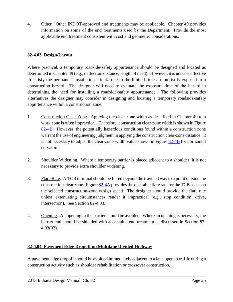
82-4.03 Design/Layout
Where practical, a temporary roadside-safety appurtenance should be designed and located as
determined in Chapter 49 (e.g., deflection distance, length of need). However, it is not cost effective
to satisfy the permanent-installation criteria due to the limited time a motorist is exposed to a
construction hazard. The designer will need to evaluate the exposure time of the hazard in
determining the need for installing a roadside-safety appurtenance. The following provides
alternatives the designer may consider in designing and locating a temporary roadside-safety
appurtenance within a construction zone.
1. Construction Clear Zone. Applying the clear-zone width as described in Chapter 49 to a
work zone is often impractical. Therefore, construction clear-zone width is shown in Figure
82-4B. However, the potentially hazardous conditions found within a construction zone
warrant the use of engineering judgment in applying the construction clear-zone distance. It
is not necessary to adjust the clear-zone-width value shown in Figure 82-4B for horizontal
curvature.
2. Shoulder Widening. Where a temporary barrier is placed adjacent to a shoulder, it is not
necessary to provide extra shoulder widening.
3. Flare Rate. A TCB terminal should be flared beyond the traveled way to a point outside the
construction clear zone. Figure 82-4A provides the desirable flare rate for the TCB based on
the selected construction-zone design speed. The designer should provide the flare rate
unless extenuating circumstances render it impractical (e.g., stop condition, drive,
intersection). See Section 82-4.03.
4. Opening. An opening in the barrier should be avoided. Where an opening is necessary, the
barrier end should be shielded with acceptable end treatment as discussed in Section 83-
4.03(03).
82-4.04 Pavement Edge Dropoff on Multilane Divided Highway
A pavement edge dropoff should be avoided immediately adjacent to a lane open to traffic during a
construction activity such as shoulder rehabilitation or crossover construction.

Page 26 2013 Indiana Design Manual, Ch. 82
In developing a traffic-maintenance plan, the desirable option is to close the lane adjacent to an edge
dropoff. This will ensure that the edge dropoff is located outside the construction clear zone.
If the traffic lane adjacent to the edge dropoff cannot be closed for an extended period of time, a full-
depth rehabilitated shoulder section should be provided that can be placed to within 3 in. of the top
of pavement elevation before the end of a day’s work. This should be done, for example, where the
shoulder work is to be done at night so that all of the existing traffic lanes can be kept open during
daylight hours. The pavement section required to fill a shoulder dropoff to within 3 in. of the top
before exposure to adjacent traffic should be obtained from the Office of Pavement Engineering. A
unique special provision will be required to address the time frame imposed on the contractor for
bringing the shoulder paving up to the required grade. Also, drums should be placed on the shoulder
dropoff, spaced as shown in Figure 83-3D, Suggested Maximum Spacing of Channelization Devices.
Where it is not feasible to limit exposure to the edge dropoff by the means described above, and the
edge dropoff is greater than 3 in., one of the mitigating measures should be considered as follows:
1. Placing a temporary wedge of material along the face of the dropoff. The wedge should
consist of asphalt material placed at a 45-deg angle or flatter. Warning signs should be
placed in advance of and throughout the treatment. A 6-in. width solid edge line should be
used to delineate the edge of the travel lane.
2. Placing drums along the traffic side of the dropoff and maintaining, if practical, a 3-ft width
buffer between the edge of the travel lane and the dropoff. Warning signs should be placed
in advance of and throughout the treatment.
3. Installing a temporary concrete barrier or other acceptable positive protection device with a
buffer between the barrier face and the traveled way. An acceptable crashworthy terminal or
flared barrier should be installed at the upstream end of the section. For nighttime use,
standard delineation devices must supplement the barrier. Specifying the use of a temporary
movable concrete barrier system will involve the use of proprietary materials.
If the work is to include deep milling or asphalt-pavement replacement, and the dropoff between
adjacent lanes is greater than 1.5 in., mitigating measure No. 1 or No. 2 should be considered.

2013 Indiana Design Manual, Ch. 82 Page 27
82-5.0 HIGHWAY CAPACITY
82-5.01 Traffic-Capacity Analysis
The need for a traffic-capacity analysis during the development of the TCP will be determined on a
project-by-project basis. A freeway reconstruction project is a candidate for analysis, as is another
project type under similar conditions. Maintaining an acceptable level-of-service during construction
is especially important on a freeway or other high-speed rural highway.
The operational elements of a facility under construction (e.g., lane segments, ramp, intersection)
should maintain a level-of-service which is not less than that provided by the facility prior to
construction, although this is not always attainable. Achieving this may require the following:
1. converting a shoulder to a travel lane;
2. eliminating on-street parking (during peak traffic-volume hours or at all times);
3. constructing a temporary lane;
4. opening additional lanes during peak traffic-volume periods;
5. providing public transportation;
6. constructing a jug-handle type configuration for an indirect left-turn at an intersection;
7. closing or metering ramps at an interchange;
8. providing a turnout along long, restrictive stretch of highway construction;
9. constructing a passing blister at a T intersection;
10. providing a two-way, left-turn lane on an urban facility;
11. adjusting signal phasing and timing at an intersection;
12. providing an additional turn lane at an intersection;
13. lengthening a turn-lane storage bay;
14. adjusting acceleration or deceleration length at an interchange ramp;
15. closing an intersection;
16. restricting turns at an intersection;
17. providing extra pavement width;
18. providing signal or flagger control in a 1-lane, two-way operation;
19. public information; or
20. providing a temporary ramp connection.
82-5.02 Queuing Analysis
A TCP developed for a freeway reconstruction project should include, at a minimum, a queuing
analysis to determine the anticipated traffic backups at particular times of the day. The results of the

Page 28 2013 Indiana Design Manual, Ch. 82
queuing analysis should be included with the proposed TCP and should be used to determine
whether or not to consider the following:
1. restricting construction operations to off-peak traffic-volume hours or nighttime;
2. closing a ramp;
3. using alternate routes;
4. developing public relations strategies; or
5. temporary widening for an extra lane or for roadway capacity.
If a queuing analysis is required, the designer should use the FHWA computer program QUEWZ or
other approved program to accomplish the task. QUEWZ is designed to evaluate a freeway work
zone, but the designer may find it useful for another type of highway with 4 or more lanes. Section
81-4.0 provides additional information on the program. The program can provide the following:
1. estimation of vehicular capacity through a work zone;
2. calculation of average speed;
3. calculation of delay through a lane-closure section;
4. calculation of queue length;
5. estimate of percentage of diverted traffic; and
6. total user cost.
82-6.0 APPLICATIONS
Section 81-2.0 discusses the factors to consider in determining which construction application to use.
The following provides the design considerations for such applications.
82-6.01 Lane or Shoulder Closure
In addition to the INDOT Standard Drawings, the designer should consider the following for a lane
or shoulder closure.
1. Taper. A lane closure, lane-width reduction, or lane shift requires the use of a transition
taper to safely shift traffic around the encroaching restriction. The designer should review
Sections 82-3.03 and 83-3.02 regarding a transition taper.
2. Sight Distance. Provide decision sight distance to the beginning of the lane closure or
transition. Section 82-3.04 provides additional information on sight distance within a
construction zone.

2013 Indiana Design Manual, Ch. 82 Page 29
3. Lane Width. Section 82-3.02 provides the Department’s criteria for reduced lane width.
4. Shoulder Usage as Travel Lane. If the TMP involves placement of traffic on the shoulder or
a portion of the shoulder, the designer should make a written request to the Office of
Pavement Engineering, regarding the shoulder’s use. The construction year AADT, percent
trucks of AADT, and the approximate length of time during which traffic is expected to use
the shoulder should be provided.
The median shoulder should be replaced with a 6-ft width section. See the INDOT Standard
Drawings. The proposed median shoulder for the new pavement section constructed in the
first phase should also be 6 ft wide. Its pavement design should be provided by the Office of
Pavement Engineering. Such shoulder will carry traffic during subsequent phases. The
entire 6-ft width should remain in place. Shoulder corrugations are to be milled into the new
shoulder after traffic is crossed over to the other roadway.
5. Lane Closure. The length of a lane closure should be held to a minimum so that the motorist
is not passing a long section of a closed lane where no work activity is occurring.
6. Roadside Safety. A roadside barrier should not be used as a transition device. A transition
should be provided with the appropriate traffic-control devices (see Chapter 83). Provide
sufficient distance between the transition devices and roadside barrier to allow an errant
motorist to safely return to the traveled way. A roadside barrier (e.g., temporary traffic
barrier) may be used as a channelization device beyond the taper. When shifting traffic to be
next to a roadside barrier, the shy distance, as discussed in Section 49-5.0, should be
provided.
7. Traffic-Control Devices. Chapter 83 and the INDOT Standard Drawings provide the
Department’s criteria for the placement of traffic-control devices.
8. Bridge. Figure 82-6A, Lane Closure on a Bridge, illustrates a TCP for closing a lane on a
bridge-reconstruction or -rehabilitation project. Figure 82-6A is applicable to a 30-ft wide
structure on a 4-lane divided facility. The designer will need to adjust the design for another
situation. Figure 82-6A provides the detail for a left-lane closure. This detail may also be
used for a right-lane closure.
9. Roadway Under Overpass Structure. Work may include full-depth bridge-deck patching,
structure removal or placement not protected by a bridge railing, or other work activity that
affects under passing lanes that are open to traffic. Such work may not take place directly
above such lanes. Appropriate warning signs and traffic-control devices should be provided

Page 30 2013 Indiana Design Manual, Ch. 82
on the under passing roadway to warn motorists of lane closures for such work. Such signs
and devices are required if no work is being done on the under passing roadway.
82-6.02 Two-Way Traffic on a Divided Highway
The following provides the considerations for where two-way traffic is to be placed onto a single
roadway of a divided highway.
1. Length. The optimum segment length is less than 4 mi. Where the segment length exceeds 4
to 5 mi, operational efficiency may be severely reduced as traffic backs up behind slower
vehicles.
2. Positive Protection.
a. Freeway. Temporary traffic barrier along with temporary solid yellow lines as shown
on the INDOT Standard Drawings should be used within each crossover and
between the crossovers to separate opposing traffic.
b. Other Multilane Roadway. Tubular markers should be used to enhance the
delineation and separation of the opposing traffic flows on each side of a temporary
double solid yellow line. The tubular markers are placed onto the pavement between
the solid yellow lines as shown on the INDOT Standard Drawings.
Where construction activities require temporary revision of traffic patterns within the
construction zone to two-lane two-way operation at or near an intersection, the end of
the temporary double solid yellow line should match the end of the existing broken
white lane line.
For a roadway with lanes which are narrower than 12 ft without paved or aggregate
shoulders, compacted aggregate size No. 73 is required where slope and ditch
conditions permit, as shown on the INDOT Standard Drawings. Such conditions
must be assessed when developing the traffic-control plan. The cross slope of each
temporary compacted aggregate shoulder is to be as shown on the INDOT Standard
Drawings. Quantities for the compacted aggregate must be determined.
3. Roadside Safety. Where traffic is directed onto the opposing roadway, the designer should
consider the effect this will have on the operational characteristics of roadside appurtenances.
For example, an existing trailing end of an unprotected bridge railing may require an

2013 Indiana Design Manual, Ch. 82 Page 31
approach-guardrail transition or impact attenuator. A blunt guardrail terminal may need to be
protected with an acceptable end treatment.
4. Crossover. The following should be considered in the design of a crossover.
a. The taper for a lane drop should not be contiguous with the crossover. See Section
82-3.03 for the acceptable taper rate and length.
b. The crossover should have a construction-zone design speed that is not more than 10
mph below the posted speed limit before the construction zone; see Section 82-3.01.
c. The crossover design should accommodate the anticipated truck traffic of the
roadway (e.g., surfacing width, loads).
d. A clear recovery area should be provided adjacent to the crossover; see Section 82-
4.04.
e. Temporary traffic barrier and the excessive use of traffic-control devices cannot
compensate for a poor geometric design of a crossover.
f. Provide signing prior to the crossover to indicate the length of the 2-way, 2-lane
section. In addition, signing may be provided within the 2-lane section indicating the
remaining distance of the 2-lane section.
5. Interchange. Maintain access to a freeway interchange ramp if the work space is in the lane
adjacent to the ramps. An additional crossover for the purpose of maintaining full
interchange access may be required. If interchange access is not feasible or presents a
capacity problem, a ramp should be closed using proper detour signing for alternative routes.
Where a ramp closure is deemed necessary, early coordination should be conducted with
local officials having jurisdiction over the affected crossroad or street. The designer should
also check that sufficient deceleration or acceleration distance is maintained where there is
work in the vicinity of an interchange ramp. If this is not practical, additional traffic control
devices or closing the ramp may be required. The designer should review the safety aspects
and conduct a capacity analysis to determine the appropriate action.
7. Capacity. Conduct a capacity analysis to ensure that traffic can be reasonably handled in the
one lane. If not, an alternate construction application should be considered (e.g., lane shift to
the shoulder).

Page 32 2013 Indiana Design Manual, Ch. 82
The needs of a left-turning motorist should be considered in developing a phased-construction scheme that reduces a 4-lane road to one lane in each direction.
82-6.03 Interstate Highways Congestion Policy [Rev. Feb. 2012] It is Department policy to prohibit operations which restrict lanes or otherwise cause congestion to occur on an Interstate Route. Such operations may not be conducted except as described in the Interstate Highways Congestion Policy (IHCP). Policy exceptions and waivers are processed through the Office of Traffic Support, Work Zone Safety Section. Waivers to a prior Interstate Lane Closure Policy remain valid. The IHCP is available for download at http://www.in.gov/indot/2731.htm. 82-6.04 Runaround or Detour In addition to the criteria shown on the INDOT Standard Drawings, a temporary runaround or specially-built detour should satisfy the geometric and roadside-safety criteria provided in Sections 82-3.0 and 82-4.0. The embankment for a temporary runaround should be shown on the mainline cross sections. If the AADT is 5,000 or greater, or if the percent trucks is 10% or greater, a project-specific pavement design is required for a temporary runaround. See the INDOT Standard Drawings for the pavement section to be used if the AADT is less than 5000, or if the percentage of trucks is less than 10%.
** PRACTICE POINTER **
Unofficial detour routes should not be shown
on the plans or described in the special provisions.

2013 Indiana Design Manual, Ch. 82 Page 33
A temporary runaround should be in accordance with the design criteria included herein. The
following Level One elements should satisfy the criteria as follows.
Element Design Criterion
1. Design speed Section 82-3.01
2. Lane width Section 82-3.02
3. Shoulder width Section 82-3.02
4. Bridge width Standard Specifications
Section 713.04
5. Structural capacity Standard Specifications
Section 713.04
6. Horizontal curvature Figure 82-3A
7. Superelevation transition length Section 82-3.05 and Chapter 43
8a. Stopping sight distance Section 82-3.04. Design speed
at horizontal curve should be used in the construction
zone. Section 43-4.0
8b. Stopping sight distance at Sag: Section 82-3.06;
vertical curve Crest: Section 82-3.04 and Chapter 44.
9. Maximum grade 3R criteria for the design
speed for the construction zone,
appropriate functional classification,
and rural or urban environment.
10. Through lane cross slope 3R criteria for the
appropriate functional classification
and rural or urban environment. If the
existing shoulder is used for through
traffic, 4% cross slope will be
acceptable.
11. Superelevation rate Section 82-3.05
12. Vertical clearance 3R criteria for the
appropriate functional classification.
13. Americans with Disabilities Act Section 51-1.08, where sidewalk
requirements exists prior to construction.
14. Bridge-railing safety performance Standard Specifications
Section 713.04
If the design for a temporary runaround or other traffic-maintenance means does not satisfy the above
criteria, a design exception must be requested. The procedure established in Section 40-8.0 should
be followed.

Page 34 2013 Indiana Design Manual, Ch. 82
The INDOT reviewer should verify that the above criteria are satisfied as part of the limited review
of a consultant-designed project.
A TCP checklist is shown as Figure 82-7A. An editable version of this form may also be found on
the Department’s website at www.in.gov/dot/div/contracts/design/dmforms/.

Participant
Project Stage Scoping
of Project
Prelim. Field Check
Hearing Final Field Check
Final Plan
Review Designer X X X X X Office of Environmental Services X X X X X Consultant (if applicable) X X X X District X X X X Federal Highway Administration (if applicable)
X X X
Communications Division (if applicable) X X X Local Public Agency (City or Town, County, School, Fire Department)
X X X X
Highway Operations Division (TMP) X X X
PARTICIPANTS DURING TRAFFIC-CONTROL-PLAN DEVELOPMENT
Figure 82-2A
2013

TRAFFIC-MAINTENANCE QUESTIONNAIRE English-Units Project
, 20
MEMORANDUM TO:
District Deputy Director ATTENTION:
District Traffic Office Manager ATTENTION:
District Design Office Manager FROM:
Project Manager SUBJECT: Traffic Maintenance for English-Units Project
Route: Des.: Project No.: Bridge File: Location: County:
Description: We are preparing plans for the project identified above and are in the process of evaluating the relative merits of a temporary bridge and runaround, maintaining traffic through the project limits, or a detour during the construction period. In order that district input may be considered in this decision, we ask that you complete the blanks in this memorandum and return it to:
Project Manager Indiana Department of Transportation 100 North Senate Ave., Room N642 Indianapolis, IN 46204-2216
If a detour is recommended, please submit the official detour map and signage with this memorandum with the blanks filled in. If the official detour route is totally over local roads, please initiate early coordination with the affected local public agency or agencies regarding the unofficial detour route. The Engineer’s Report recommended the following:
a temporary runaround should be used;
2013

traffic should be maintained through the project limits; an official detour should be used.
The AADT during the construction year is
A. TRAFFIC-MAINTENANCE OPTIONS ANALYSIS
1. OPTION 1: TEMPORARY RUNAROUND
RUNAROUND COMPUTATIONS FURNISHED BY DESIGNER Length of Runaround, ft* x Cost per Foot** ft x $ = $ Length of Temporary Bridge x $1,000/ft or Cost of Pipe
ft x $1,000 = $
$ Total Runaround Cost (Total Cost Option 1) $
* Length of Runaround = Distance from tie-in point to tie-in point minus Length of
Temporary Bridge.
** For average fill height ≤ 6 ft, use $120/ft For average fill height > 6 ft, increase as necessary
2. OPTION 2: TRAFFIC MAINTAINED THROUGH PROJECT LIMITS
Length of Roadway Treatment, ft* x Cost per Foot* ft x $ = $ Length of Temporary Concrete Barrier x Cost per Foot ft x $ = $ Cost of Crossovers $ Total Maintained-Traffic Cost (Total Cost Option 2)
$
3. OPTION 3: INDOT-ROUTES OFFICIAL DETOUR a. Best available official detour route over INDOT routes:
b. Extra distance to be traveled by through traffic using this route: mi
c. Percent of the traffic which would use this detour route: % d. Road(s) that would be used as an unofficial detour route:
2013

(1) Existing condition and type of pavement for each road, (i.e., good, very good,
rutted, gravel, asphalt, etc.)
(2) Distance over the above unofficial detour route: mi
INDOT-ROUTES OFFICIAL-DETOUR COMPUTATIONS
Detour Through Local Detour Duration (days) Extra Distance (mi) Vehicles per Day User Cost per Mile $0.30 $0.30 Total User Cost $ $
User Cost = Detour Duration x Extra Distance x Vehicles per Day x $0.30/mi
e. Total User Cost = Through User Cost + Local User Cost. Therefore, Total User Cost
= $ . f. Estimated payment to local public agencies due to use of unofficial detour route
= $ .
Total Cost Option 3 (e + f) $
4. OPTION 4: LOCAL-ROADS OFFICIAL DETOUR
a. Best available official detour route over local roads. It is feasible for this route to include one or more INDOT routes.
b. Extra distance to be traveled by through traffic using this route: mi
c. Percent of the traffic which would use this detour route: % d. Cost to upgrade the local roads to accommodate INDOT traffic:
$ e. Existing condition and type of pavement for each road. (i.e., good, very good, rutted,
gravel, asphalt, etc.)
LOCAL-ROADS OFFICIAL DETOUR COMPUTATIONS
Detour Through Local Detour Duration (days)
2013

Extra Distance (mi) Vehicles per Day User Cost per Mile $0.30 $0.30 User Cost $ $ Cost to Improve Local Roads (See Item 3b)
$ n/a
User cost = Detour Duration x Extra Distance x Vehicles per Day x $0.30/mi
Total User cost = Through User Cost + Local User Cost + Cost to Improve Local Roads. Therefore, Total Cost Option 4 = $
B. AFFECTS OF PROJECT WORK ON PUBLIC SERVICES
1. TIME DELAYS Fire and police protection: min Emergency medical service: min Postal service: min
2. SCHOOL BUSES
Number of school buses using the facility per day: Additional travel distance required per bus: mi Total additional school-bus travel distance required mi
3. BUSINESSES AND PUBLIC FACILITIES
Businesses or public facilities which are sensitive to the presence of this road work, and the degree of impact the work would have:
C. DISTRICT RECOMMENDATION
1. RECOMMENDATION: Rationale for this recommendation if it is different than what is included in the Engineer’s Report:
2. DETOUR ROUTE MARKER ASSEMBLIES:
If an official detour is recommended, detour route marker assemblies will be required.
3. MAP OF OFFICIAL DETOUR:
If an official detour is recommended, a map of the detour with sign locations is shown on an accompanying sheet.
2013

Construction Zone Design
Speed, V (mph)
fmax for Open-Roadway
Conditions
Normal Crown Section Minimum Radius, Rmin (ft),
e = -0.02
Superelevated Section Minimum Radius, Rmin (ft),
e= +0.08 20 0.17 180 110 25 0.17 280 170 30 0.16 430 250 35 0.15 630 360 40 0.15 820 470 45 0.14 1130 620 50 0.14 1390 760 55 0.13 1840 960
Notes: 1. Curve Radius. The radius is calculated from the equation as follows:
; )f + (e 1
V = R2
maxmin 5
Value shown in the table for design has been rounded up to the next higher 10-ft increment.
2. Normal-Crown Section. If the normal-crown section is maintained through the horizontal
curve, the superelevation rate is -0.02 assuming a typical cross slope of 2%. Therefore, the Rmin column with e = -0.02 lists the minimum radius which can be used if retaining the normal section through the horizontal curve.
3. Other Radius. For a proposed radius or superelevation rate intermediate between the table
values, the equation in Note 1 may be used to determine the proper curvature layout. For example, if the construction-zone design speed is 55 mph and the proposed curve radius is 1000 ft, the superelevation rate is determined as follows:
f - R 1
V = e2
5
.12 - ))((1
)( = e2
010005
55
07.0+ = e
MINIMUM RADIUS FOR HORIZONTAL CURVE
IN CONSTRUCTION ZONE
Figure 82-3A
2013

Construction-Zone
Design Speed (mph)
Calculated K Value
(K = V2/46.5)
K Value Rounded For
Design 20 8.6 9 25 13.4 14 30 19.4 20 35 26.3 27 40 34.4 35 45 43.5 44 50 53.8 54 55 65.1 66
KA = AV = L2
5.46
Where:
L = Length of vertical curve, ft A = Algebraic difference between grades, % K = Horizontal distance required to effect a 1% change in gradient V = Design speed, mph
K VALUE FOR SAG VERTICAL CURVE (Comfort Criteria in a Construction Zone)
Figure 82-3B
2013

2013

Construction-Zone Design Speed
Cut Slope Fill Slope
3:1 4:1 5:1 6:1 Flatter
Than 6:1 6:1 5:1 4:1 3:1
40 mph or lower 8 8 8 8 8 8 8 8 10 See Note
2
45 mph 8 8 8 8 8 8 10 10 12 50 mph 8 10 10 10 10 10 12 13 15 55 mph 8 12 12 12 12 12 13 15 18
Notes:
1. Width is measured from the edge of traveled way.
2. For a facility with 3:1 fill slopes, the clear-zone width shown above should be used in conjunction with the procedures described in Section 49-2.03(01).
CLEAR-ZONE WIDTH (ft) FOR CONSTRUCTION ZONE
Figure 82-4B
2013

2013

This figure deleted. For related information, see the Interstate Highways Congestion Policy (IHCP), available for download at http://www.in.gov/indot/2731.htm.
INTERSTATE LANE CLOSURE POLICY – STATEWIDE Figure 82-6B
2013

This figure deleted. For related information, see the Interstate Highways Congestion Policy (IHCP), available for download at http://www.in.gov/indot/2731.htm.
INTERSTATE LANE CLOSURE POLICY – SELECTED URBAN AREAS Figure 82-6C
2013

TRAFFIC-CONTROL-PLAN CHECKLIST Route Des GENERAL INFORMATION
YES NO n/a On Plans
1. Has a transportation management plan been developed?
a. Have all recommendations been implemented? b. Has Environmental Policy Team been notified of
major changes?
2. Have all applicable work-zone types listed below been adequately considered?
a. Work outside of roadway b. Lane constriction c. Lane closure d. One-lane, two-way operation e. Runaround f. Intermittent closure g. Use of shoulder or median as travelway h. Crossovers i. Two-way traffic on one roadway of divided facility j. Detour
3. Has all information listed below been incorporated into the contract plans?
a. INDOT Standard Drawings b. INDOT Standard Specifications c. Recurring special provisions d. Unique special provisions e. Detail plans
4. Will extra publicity be required prior to letting (e.g., radio, T.V., newspaper, clubs)?
5. The contractor can restrict the roadway during:
a. Morning or evening rush hour i. One direction ii. Both directions
b. Local celebration c. Holidays or weekends d. Other special event: e. Overnight
6. Nighttime hours of operation required? If Yes, When? a. Between p.m. and a.m.
b. Are special precautions needed (e.g., lighting, clearance lights on equipment)?
2013

GENERAL INFORMATION (Cont’d.) YES NO n/a On Plans 7. Are there changes that cannot be made concurrently for
traffic routing, fire, police, etc.? If Yes, What?
8. Can two adjacent street or road crossings be closed at the same time? If Yes, where or which ones?
9. Will the source of material from off the project site interfere with traffic?
a. On and off project limits b. Certain roads may not be used (e.g., environmental,
recreational). If Yes, which ones?
10. Is the contractor required to provide advance notice for a change in traffic pattern?
11. The starting or completion date is controlled by:
a. School closings or openings b. Holiday: c. Other projects d. Sporting event: e. Other:
12. Are there present or future contracts in the immediate area that may affect traffic or the Contractor’s operations?
DETOUR YES NO n/a On Plans 1. Will traffic be detoured? If Yes, is the detour adequate
in terms of:
a. Weight restriction b. Height – width c. Wide load d. Capacity e. Adequate traffic-control devices f. Railroad crossing and controls g. Geometrics (turning radius, etc.) h. Restriction on bridge or other structure
If No for a. through h., what correctives can be taken?
2. Will trucks using the detour conflict with other traffic using the detour?
2013

DETOUR (Cont’d.) YES NO n/a On Plans 3. Will there be other construction along the detour that
can influence traffic flow?
4. Have other affected Districts or States been notified? 5. If the detour is to be established on ot her than a State
highway, has contact been made with:
a. County? b. City? c. Town?
6. Will there be an unofficial detour? If Yes, has a Letter of Understanding been sent to the local officials?
7. Will all fronting businesses have acceptable ingress and egress?
8. Can the detour be continued over winter (snow removal)?
9. Are alternate routes available to local motorists? 10. Should the following be contacted?
a. Public-school system b. Public-transit system c. Police, fire, or ambulance services d. Postal mail-route service e. Others:
If any Yes, list who and when, with telephone numbers.
11. Has the District established a detour route? WORK ZONE YES NO n/a On Plans 1. Will capacity be restricted? If Yes, what is extent of
restriction?
a. Where will excess traffic be diverted?
b. Can an alternate route handle the traffic?
2013
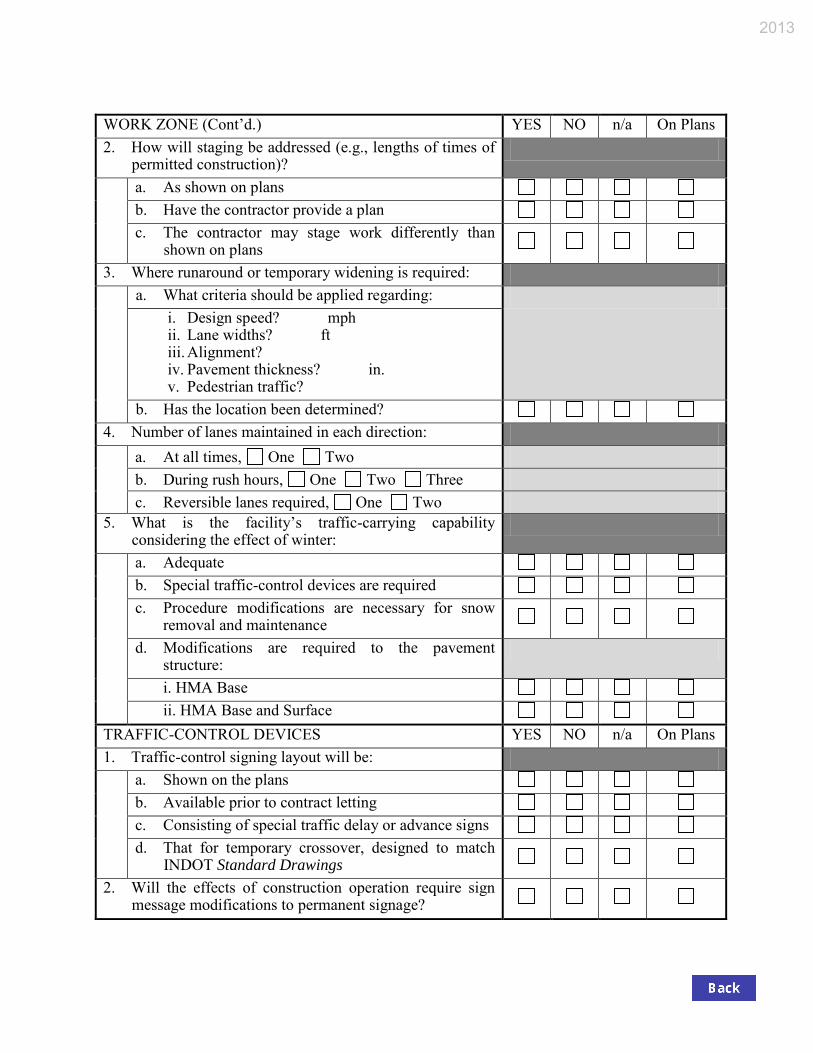
WORK ZONE (Cont’d.) YES NO n/a On Plans 2. How will staging be addressed (e.g., lengths of times of
permitted construction)?
a. As shown on plans b. Have the contractor provide a plan c. The contractor may stage work differently than
shown on plans
3. Where runaround or temporary widening is required:
a. What criteria should be applied regarding: i. Design speed? mph ii. Lane widths? ft iii. Alignment? iv. Pavement thickness? in. v. Pedestrian traffic?
b. Has the location been determined? 4. Number of lanes maintained in each direction:
a. At all times, One Two b. During rush hours, One Two Three c. Reversible lanes required, One Two
5. What is the facility’s traffic-carrying capability considering the effect of winter:
a. Adequate b. Special traffic-control devices are required c. Procedure modifications are necessary for snow removal and maintenance
d. Modifications are required to the pavement structure:
i. HMA Base ii. HMA Base and Surface
TRAFFIC-CONTROL DEVICES YES NO n/a On Plans 1. Traffic-control signing layout will be:
a. Shown on the plans b. Available prior to contract letting c. Consisting of special traffic delay or advance signs d. That for temporary crossover, designed to match
INDOT Standard Drawings
2. Will the effects of construction operation require sign message modifications to permanent signage?
2013

TRAFFIC-CONTROL DEVICES (Cont’d.) YES NO n/a On Plans 3. Are temporary traffic signals required?
a. Equipment type: i. Manual ii. Fixed timed iii. Actuated b. Will existing signals need to be kept operational? c. Has an agreement been reached with the local
municipality?
4. Will temporary street lighting be needed? If Yes, what type of equipment?
a. Wood poles b. Breakaway poles c. Agreement with power company required?
5. Which temporary pavement markings are required?
a. Paint b. Tape c. Raised pavement markers
6. Striping removal required of:
a. Center line / Lane lines b. Right edge line c. Left edge line d. Both edge lines
7. Flashing warning lights required for:
a. Equipment kept overnight within 30 ft of traveled way
b. All barricades and warning signs c. Construction roadside hazards
8. Steady-burn warning lights required for:
a. Edge of travelway, dropoff of in. b. Channelizing traffic
9. Have speed limits been considered? If Yes, what limits?
a. Work zone, mph b. Worksite, mph c. Minimum, mph d. Advisory, mph
2013

ROADSIDE SAFETY YES NO n/a On Plans 1. Temporary barriers
a. Required for traffic protection b. Required for workers’ protection c. Delineation of barriers provided by: i. Electrical devices ii. Reflectorization d. Upon completion of project, retained by: i. Department ii. Contractor
2. Will temporary impact attenuators be required? If Yes, Type
3. Extra protection will be required for:
a. Pedestrians b. School area and crossings c. Playground or park d. Type of protection:
4. Where may the contractor store equipment, construction material, or waste material?
a. On site with flashers or other protection b. 30 ft or more from edge of traveled way c. Designated storage site
5. Where may contractor’s employees park personal vehicles?
a. On-site b. Off-site
2013


![Hydraulics and Drainage Design - Indianain.gov/indot/design_manual/files/Ch203_2013.pdf · 203-2.02(14) Pipe or Box Extension Structure Sizing [Rev. May 2013, Apr. 2017]..... 17 ...](https://static.fdocuments.us/doc/165x107/5aa2d9257f8b9ac67a8d9ea1/hydraulics-and-drainage-design-14-pipe-or-box-extension-structure-sizing-rev.jpg)