Chapter 8 Internal Forced Convection ...ocw.nthu.edu.tw/ocw/upload/77/896/HTchap8.pdfInternal Forced...
18
Chapter 8 Internal Forced Convection
Transcript of Chapter 8 Internal Forced Convection ...ocw.nthu.edu.tw/ocw/upload/77/896/HTchap8.pdfInternal Forced...

Chapter 8
Internal Forced Convection
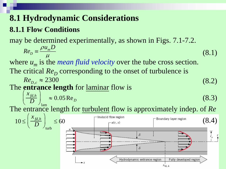
8.1 Hydrodynamic Considerations8.1.1 Flow Conditionsmay be determined experimentally, as shown in Figs. 7.1-7.2.
where um is the mean fluid velocity over the tube cross section.The critical ReD corresponding to the onset of turbulence is
The entrance length for laminar flow is
The entrance length for turbulent flow is approximately indep. of Re
(8.1)mD
u DRe ρμ≡
, 2300D cRe ≈
x fd,hD
⎛
⎝ ⎜
⎞
⎠ ⎟
lam≈ 0.05 ReD
10 ≤x fd,h
D⎛
⎝ ⎜
⎞
⎠ ⎟
turb≤ 60
(8.2)
(8.3)
(8.4)

8.1.2 The mean Velocity
8.1.3 Velocity Profile in the Fully Developed RegionThe velocity profile of a fully developed laminar flow is parabolic
as shown in (8.13)-(8.15).
8.1.4 Pressure Gradient and Friction Factor in Fully Developed FlowFriction factor for laminar flow:
Friction factor for turbulent flow: (8.20) or (8.21) or Fig. 8.3.Pressure drop:
0
2 00
( , ) 2 ( , )cc rA
mc
u r x dAu u r x rdr
A r
ρ
ρ= =
∫∫ (8.8)
(8.19)64D
f Re=
2 2
1 1
2 2
2 1( )2 2
p xm mp x
u up dp f dx f x xD D
ρ ρΔ = − = = −∫ ∫ (8.22a)
22
00
1( ) 14
dp ru r rdx rμ
⎡ ⎤⎛ ⎞⎛ ⎞ ⎢ ⎥= − − ⎜ ⎟⎜ ⎟⎝ ⎠ ⎢ ⎥⎝ ⎠⎣ ⎦
(8.13)


8.2 Thermal Considerations
The thermal entrance length for laminar flow is
The thermal entrance length for turbulent flow is
fd,
lam
0.05tD
xRe PrD
⎛ ⎞≈⎜ ⎟
⎝ ⎠
xfd,tD
⎛ ⎝ ⎜
⎞ ⎠ ⎟
turb≈ 10
(8.23)
(8.24)

8.2.1 The Mean Temperature
For incompressible flow in a circular tube with constant cp,
8.2.2 Newton's Law of Cooling
where h is the local convection heat transfer coefficient.This relation applies for different wall conditions, e.g., Ts= C or q”= C.Since Tm usually varies along the tube, the variation of Tm must be accounted for.
(8.25)
(8.26)
(8.27)
p
A cp
m cmTdAuc
T c
&
∫=
ρ
Tm = 2umr0
2 uTrdr0r0∫
qs" = h(Ts − Tm )

8.2.3 Fully Developed ConditionsThe thermally fully developed condition is when the relative shape
of the profile no longer changes and is stated as
(8.29)
(8.28)∂∂x
Ts (x) − T (r, x)Ts (x) − Tm (x)
⎡ ⎣ ⎢
⎤ ⎦ ⎥
fd,t= 0
0
0
/( )r rs
s m s mr r
T rT T h f xkr T T T T=
=
−∂ ∂⎛ ⎞−∂= = − ≠⎜ ⎟∂ − −⎝ ⎠
Hence, in the thermally fully developed flow of a fluid with constant properties, the local convection coefficient is a constant. (Fig. 8.5)
for cases with either a uniform surface heat flux or a uniform surface temperature. Since the term in the bracket of (8.29) is independent of x, its r-derivative is also independent of x. So,
Eq. (8.28) implies
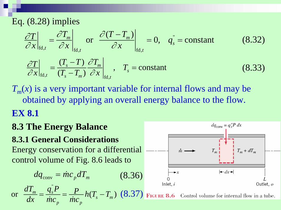
Tm(x) is a very important variable for internal flows and may be obtained by applying an overall energy balance to the flow.
EX 8.18.3 The Energy Balance8.3.1 General Considerations
(8.32)
(8.33)
"
fd, fd, fd,
( )or 0, constantm ms
t t t
T T TT qx x x∂ ∂∂
∂ ∂ ∂−
= = =
fd, fd,
( ) , constant( )s m
st s m t
T T TT Tx T T x∂∂
∂ ∂−
= =−
Energy conservation for a differential control volume of Fig. 8.6 leads to
mpdTcmdq &=conv
"
or ( )m ss m
p p
dT q P P h T Tdx mc mc= = −& &
(8.36)
(8.37)

8.3.2 Constant Surface Heat Flux
(8.40)"
",( ) , constants
m m i sp
q PT x T x qmc= + =&
EX. 8.2

8.3.3 Constant Surface TemperatureDefine ΔT = Ts - Tm, Eq. 8.37 becomes
Integration leads to
From energy balance,
Substituting for from (8.41a), we obtain
This means for constant Ts, the total qconv is proportional to and the log mean temperature difference ΔTlm.
ThcmP
dxTd
dxdT
p
m Δ=Δ−=&
)(
Lp
L
pi
o hcmPLhdxLcm
PLTT
&&−=⎟
⎠⎞⎜
⎝⎛−=
ΔΔ
∫01ln
,
( )Then, exp , constants ms
s m i p
T T x Px h TT T mc⎛ ⎞−
= − =⎜ ⎟− ⎝ ⎠&
)()]()[()( ,,,,conv oipomsimspimomp TTcmTTTTcmTTcmq Δ−Δ=−−−=−= &&&
conv lm lm, , constantln( / )o i
s so i
T Tq hA T T TT TΔ − Δ
= Δ Δ ≡ =Δ Δ
pcm&
h
(8.42)
(8.44)
(8.41a)

In many applications, the temperature of an external fluid, rather than the tube surface temperature, is fixed (Fig. 8.8). The previous formulae can still be applied (with modification adopting the concept of thermal resistance), as indicated by Eqs. (8.45) and (8.46).
EX 8.3
,
,expm oo s
i m i p
T TT UAT T T mc
∞
∞
− ⎛ ⎞Δ= = −⎜ ⎟Δ − ⎝ ⎠&
lmsq UA T= Δ
,
, tot
1expm oo
i m i p
T TTT T T mc R
∞
∞
− ⎛ ⎞Δ= = −⎜ ⎟Δ − ⎝ ⎠&
lm
tot
TqR
Δ=
(8.45a)
(8.46a)
(8.45b)
(8.46b)
8.4 Laminar Flow in Circular Tubes: Thermal Analysis8.4.1 The Fully Developed Region
For the case of uniform surface heat flux, the exact correlation is
For the case of constant surface temp., with
EXs. 8.4, 8.5
"4.36, constantD shDNu qk≡ = =
3.66, constantD sNu T= =
(∂2T/∂2x)<< (∂2T/∂2r)(8.53)
(8.55)

8.4.2 The Entry RegionThermal entry length problem → (8.56)
Combined entry length problem → (8.57)

Fully Developed Pipe Flow
For Pr < 1 entrance region
fully-developed region
velocity boundary layerthermal boundary layer

8.5 Convection Correlations: Turbulent Flow in Circular TubesUsing the modified Reynolds analogy, there are (8.58)-(8.60).(Note the exponent of ReD is 4/5).For higher accuracies, use (8.61)-(8.62).EX 8.6
8.6 Convection Correlations: Noncircular Tubes and the Concentric Tube Annulus
Hydraulic diameter: (8.66)
It is this diameter that should be used in calculating parameters such as ReD and NuD.For turbulent flow, it is reasonable to use the correlations of Section 8.5 for Pr > 0.7. However, the coefficient is presumed to be an average over the perimeter.For laminar flow, the use of circular tube correlations is less accurate, particularly with cross sections characterized by sharp corners. For laminar fully developed conditions: use Table 8.1
Dh ≡4AcP

Fully Developed Laminar Flow in Noncircular TubesHydraulic diameter:
Dh ≡4AcP
constant
Re constanth
h
D
hDNu kf
= =
=
∴ as Dh ↓
→ h and ΔP ↑
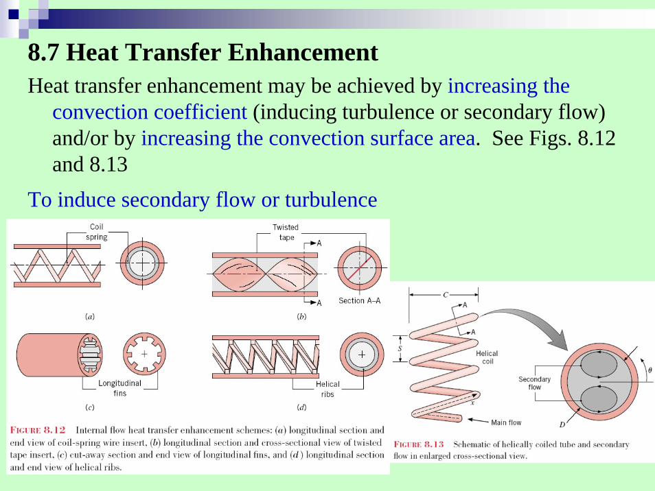
8.7 Heat Transfer EnhancementHeat transfer enhancement may be achieved by increasing the
convection coefficient (inducing turbulence or secondary flow) and/or by increasing the convection surface area. See Figs. 8.12 and 8.13
To induce secondary flow or turbulence

8.8 Microscale Internal FlowMany new technologies involve microscale internal flow
with Dh≦100μm.For gases, the results of Chapters 6 through 8 are not expected to apply when Dh /λmfp ≦10.For liquids, some features of previous results, e.g., friction factor (8.19), pressure drop (8.22a), and transition criterion (8.2) remain applicable.
8.9 Convection Mass TransferOmitted.