CHAPTER 7 RESULTS OF NATURAL CONDITION SURVEYS AND...
69
CHAPTER 7 RESULTS OF NATURAL CONDITION SURVEYS AND HYDROLOGICAL ANALYSES
Transcript of CHAPTER 7 RESULTS OF NATURAL CONDITION SURVEYS AND...

CHAPTER 7
RESULTS OF NATURAL
CONDITION SURVEYS AND
HYDROLOGICAL ANALYSES

Project for the Study on Development of the Sena Corridor Final Report
Chapter 7 Results of Natural Condition Survey and Hydrological Analyses
7 - 1
Chapter 7 Results of Natural Condition Surveys and Hydrological
Analyses
7.1 Results of Natural Condition Surveys
7.1.1 Topographical Survey
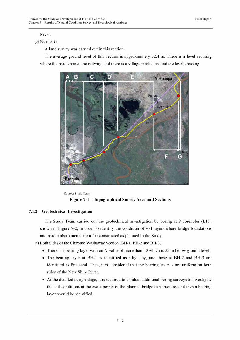
The Study Team carried out a topographical survey for areas described below and shown in
Figure 7-1.
a) Section A
A land survey was carried out in this section.
The average ground level of this section is approximately 48.3 m (elevation). The distance
between the road and railway ranges from 16 m to 110 m. The intersection of the M1 route with
the S151 route has already been upgraded and approximately 140 m of the S151 route from the
roundabout has also been upgraded as a paved road.
b) Section B
A land survey, a centre line and cross section survey for the existing road and railway line,
and a river cross section survey for the Chiromo washaway section were carried out in this
section.
The average ground level of this section is approximately 46.7 m. The distance between the
road and railway ranges from 16 m to 110 m. The length of embankment lost due to flooding is
approximately 80 m for the road and 350 m for the railway.
c) Section C
A land survey, and a centre line and cross section survey for the existing road and railway
line were carried out in this section.
The average ground level of this section is approximately 46.7 m. The distance between the
road and railway is 100 m as they are parallel. There is a wetland.
d) Section D
A land survey, a centre line and cross section survey for the existing road and railway line,
and a river cross section survey for the Shire River were carried out in this section.
The average ground level of this section is approximately 47.2 m. There is a combined road
and railway bridge over the Shire River.
e) Section E
A land survey was carried out in this section.
The average ground level of this section is approximately 48.4 m. The distance between the
road and railway ranges from 100 m to 380 m. There is a grave site and an irrigation facility.
f) Section F
A land survey was carried out in this section.
The average ground level of this section is approximately 50.1 m. The distance between the
road and railway ranges from 380 m to 730 m. The S151 approaches up to 30 m from the Ruo
Project for the Study on Development of the Sena Corridor Final Report
Chapter 7 Results of Natural Condition Survey and Hydrological Analyses
7 - 2
River.
g) Section G
A land survey was carried out in this section.
The average ground level of this section is approximately 52.4 m. There is a level crossing
where the road crosses the railway, and there is a village market around the level crossing.
Source: Study Team
Figure 7-1 Topographical Survey Area and Sections
7.1.2 Geotechnical Investigation
The Study Team carried out the geotechnical investigation by boring at 8 boreholes (BH),
shown in Figure 7-2, in order to identify the condition of soil layers where bridge foundations
and road embankments are to be constructed as planned in the Study.
a) Both Sides of the Chiromo Washaway Section (BH-1, BH-2 and BH-3)
• There is a bearing layer with an N-value of more than 50 which is 25 m below ground level.
• The bearing layer at BH-1 is identified as silty clay, and those at BH-2 and BH-3 are
identified as fine sand. Thus, it is considered that the bearing layer is not uniform on both
sides of the New Shire River.
• At the detailed design stage, it is required to conduct additional boring surveys to investigate
the soil conditions at the exact points of the planned bridge substructure, and then a bearing
layer should be identified.
A B C D E
F G

Project for the Study on Development of the Sena Corridor Final Report
Chapter 7 Results of Natural Condition Survey and Hydrological Analyses
7 - 3
Source: Study Team
Figure 7-2 Location of Boreholes and Boring Logs
b) Existing Road between the Chiromo Washaway Section and the Kamuzu Truss Bridge (BH-4 and
BH-5)
The top 1.45-m layer is composed of silty sandy gravel (fill material). From 1.45 m down to
6.00 m, there is a layer of sandy silty clay. It is considered that this sandy silty clay layer would
not require soft soil measures because its N-value is 10.
c) Both Sides of the Kamuzu Truss Bridge (BH-6 and BH-7)
• There is a layer with an N-value of more than 50 extending from 13.45 m to 18.45 m at
BH-6. However, the soil layer changes below 19.45 m and its N-value is approximately 20.
• Looking at the results of BH-7, there is no layer within 45 m from ground level which has
an N-value of more than 50.
• It is considered that the bearing layer is not uniform on both sides of New Shire River. At
the detailed design stage, it is required to conduct additional boring surveys to investigate
the soil conditions at the exact points of the planned bridge substructure, and then a bearing
layer should be identified.
• Regarding the silty sand layer from ground level down to 6.00 m at BH-6, soft soil measures
may need to be taken because the N-value is less than 10. An additional boring survey will
be required at the detailed design stage to investigate the soil conditions in detail. If it is
found that soft soil measures need to be taken, the stability of the designed embankment
should be considered.

Project for the Study on Development of the Sena Corridor Final Report
Chapter 7 Results of Natural Condition Survey and Hydrological Analyses
7 - 4
d) At the eastern side of the Kamuzu Truss Bridge (BH-8)
The top 2.45-m layer is composed of sandy clay silt with an N-value of 2, for which soft soil
measures will need to be taken. There is silty medium coarse sand from 2.45 m down to 5.45 m
with an N-value of around 5, so soft soil measures may need to be taken. An additional boring
survey will be required at the detailed design stage to investigate the soil conditions in detail. If
it is found that soft soil measures need to be taken, the stability of the designed embankment
should be considered.
7.1.3 Hydrological Data
The Study Team collected the following hydrological data from the hydrological observation
stations of the Ministry of Irrigation and Water Resources (MoIWR):
a) Data of the Shire River at the Chiromo observation station
• Water level data: 39 years from November 1970 to December 2009
• Water discharge data: 39 years from November 1970 to December 2009
b) Data of the Shire River at the Liwonde observation station
• Water discharge data: 12 years from November 1999 to April 2010
There have been no hydrological observations for the Chiromo washaway since it occurred in
1997. A water gauge was installed by the MoIWR on the upstream side of the road embankment
in 2008 and used to measure the water level. However, this water gauge was lost due to floods
and no water level data is available for the relevant period.
In order to estimate the discharge volume from the survey of current velocity, the Study
Team installed two water gauges (one for lower water level and the other for higher water level)
beside the road embankment on the Bangula side of the river.
The Study Team also carried current velocity surveys out at both the Chiromo washaway
section and near the existing Kamuzu Truss Bridge in order to estimate the discharge volume.
7.2 Results of Hydrological Analyses of the Shire River and Washaway Section
7.2.1 Results of Hydraulic and Hydrological Analyses
Based on collected aerial photos, hydrological data, hydraulic observation data, site
investigations and interviews with local residents, the hydraulic conditions of the Shire River,
the New Shire River and the Ruo River have been analysed.
(1) Conditions of Rivers
a) Shire River
1) Outline of Basin
The Shire River originates from the Lake Malawi and is the longest river in the country. Its
basin consists of various rivers not only in Malawi, but also in Tanzania and Mozambique, and
the catchment area of the Kamuzu Truss Bridge is about 149,500 km2. The river flows from the
Project for the Study on Development of the Sena Corridor Final Report
Chapter 7 Results of Natural Condition Survey and Hydrological Analyses
7 - 5
southern edge of the Great Rift Valley at Lake Malawi and passes through Lake Malombe. The
gradient becomes steep near Liwonde, passing through three hydropower stations. It gathers
many tributaries and flows in the middle of wide marshes, such as the Elephant Marsh with a
gentle gradient, and joins the large left tributary, the Ruo River. About 8 km further downstream,
it then joins the right tributary, the New Shire River, and finally joins the large Zambezi River
in Mozambique and flows into the Indian Ocean.
2) River Discharge Volume
The Shire River constantly flows from Lake Malawi, bringing large quantities of water to the
marshes upstream of Kamuzu Truss Bridge. The average annual discharge volume is 620 m3/sec,
while the average monthly discharge volume in the rainy season is 910 m3/sec and the minimum
monthly discharge volume in the dry season is 264 m3/sec.
According to the data for the last 39 years, the maximum daily discharge volume is observed
in the rainy season between January and March, with volumes of just under 1,200 m3/sec.
3) Confluence with the Ruo River
The Shire River merges with the Ruo River downstream of Kamuzu Truss Bridge at Chiromo.
When the Ruo River becomes full during the rainy season, it easily floods near the confluence
due to insufficient discharge capacity. This flood caused by the Ruo River spreads into the flood
plain and increases the water level at the confluence. This causes backflow of the Shire River,
with the water flowing into the marshes.
This backward flow on the Shire River continues for as long as the Ruo River is full and the
water level of the marshes of the Shire River is high. When the overflow of the Ruo River is
almost complete, the water level at the confluence decreases and the current of the Shire River
returns to normal flow.
4) Marsh of the Shire River
The Shire River enters a wide marsh, called Elephant Marsh, near Chikwawa. The catchment
areas of most rivers flowing into the marsh from the north-eastern and western mountain ranges
are small with limited rainfall. The total discharge volume is therefore limited for a short period.
However, since the New Shire River was formed at the washaway section and it is now
possible for water to accumulate, a clear river line was formed for a wadi from the western
Bangula side. It is assumed that water in this wadi during the rainy season gently flowed into
the very wet marsh on the surface and did not form a clear river line.
b) New Shire River
1) Upstream of the Chiromo Washaway Section
The New Shire River separates from the Shire River about 2 km upstream of the Kamuzu
Truss Bridge, flows toward the railway embankment at an angle of about 45 degrees, flows
along the embankment, and then changes direction by almost 90º and flows into the washaway
section.
The width of the river at the washaway section is almost 90 m on average during the dry
Project for the Study on Development of the Sena Corridor Final Report
Chapter 7 Results of Natural Condition Survey and Hydrological Analyses
7 - 6
season, and even though the water depth on the right side of the marsh is shallow, the water on
the left side of the river quickly becomes deep, reaching about 5 m.
2) Chiromo Washaway Section
At the Chiromo washaway section, the railway embankment was washed away for about 300
m in length. The lower part of the embankment on the Bangula side has not been scoured and
this part appears during the dry season. On the other hand, the edge of the railway embankment
on the left side of the river has been severely scoured.
The distance between the edge of the remaining road on the Bangula side and the slope used
as the landing point for boats is about 60 m in the dry season and 90 m in the rainy season. The
river cross section is almost V-shaped and the water depth at the centre is 5 m in the dry season,
while the deepest part is almost 10 m. Since there is continuous flow of water even in the dry
season, this part of the river does not dry up.
3) Downstream of the Washaway Section
After passing the narrow part by the edge of the remaining road from Bangula, the width of
the river is about 200 m and the average water depth is 4–5 m. The deepest part is about 10 m,
except where there are islands within the river basin. The New Shire River then flows in the
marsh downstream of the washaway section and reaches the confluence with the Shire River
about 8 km from the washaway section.
At the confluence, the flow line which discharges the water of the New Shire River is clear
and the same quantity of discharge volume flows, since there is no major obstacle in the marsh.
As a result, there is no problem of discharge capacity of the New Shire River, which smoothly
flows even during floods.
c) Ruo River
The Ruo River flows along the border between Malawi and Mozambique. The origin of the
Ruo River is Mount Mulanje which has heavy precipitation, causing a large water discharge
volume in the rainy season. It flows in a V-shaped valley in the mountainous section and the
gradient of the riverbed is steep, so the flow is fast and contains mud and sand. The catchment
area at the confluence is 4,530 km2.
The riverbed gradient becomes gentle near Makhanga where the terrain is flat and large
quantities of deposits remain in the river. The Ruo River merges with the Shire River after the
flowing capacity drastically decreases. At this section, the width of the river is about 200 m and
the river meanders in the sandbank.
At the confluence with the Shire River, the river width is about 80 m and the height of the
low water channel is about 3–4 m with very limited water flow during the dry season.
Assuming the current velocity is 5 m/s, the discharge capacity is estimated at about 1,600
m3/sec. Since several floods with discharge volume exceeding 2,000 m
3/sec have been recorded
in the past, it is assumed that floods often occur.
The populated area of Makhanga is located on the natural embankment formed by the Ruo
Project for the Study on Development of the Sena Corridor Final Report
Chapter 7 Results of Natural Condition Survey and Hydrological Analyses
7 - 7
River and is very close to the right bank of the river. Since the Ruo River starts flooding where
the terrain changes from mountainous to flat with siltation problems, parts of Makhanga where
the natural embankment is not well formed are often flooded. According to interviews with
local residents, the lower area near the market is often flooded up to the foundations of houses.
In the past, the whole area including the railway line, which is located on the highest ground,
was covered by flood water. When the Ruo River floods, S151 is also inundated and becomes
impassable for some time. In addition, erosion of the Ruo River bank near Makhanga is a
serious problem. In order to prevent flooding in Makhanga, suitable protection measures should
be studied under the comprehensive flood control study, in coordination with the GoMZ, since
the Ruo River is a border river.
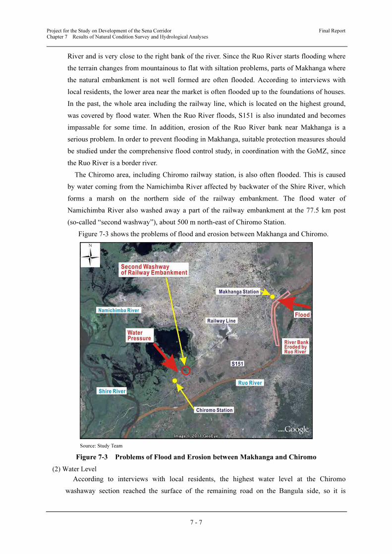
The Chiromo area, including Chiromo railway station, is also often flooded. This is caused
by water coming from the Namichimba River affected by backwater of the Shire River, which
forms a marsh on the northern side of the railway embankment. The flood water of
Namichimba River also washed away a part of the railway embankment at the 77.5 km post
(so-called “second washway”), about 500 m north-east of Chiromo Station.
Figure 7-3 shows the problems of flood and erosion between Makhanga and Chiromo.
Source: Study Team
Figure 7-3 Problems of Flood and Erosion between Makhanga and Chiromo
(2) Water Level
According to interviews with local residents, the highest water level at the Chiromo
washaway section reached the surface of the remaining road on the Bangula side, so it is
Project for the Study on Development of the Sena Corridor Final Report
Chapter 7 Results of Natural Condition Survey and Hydrological Analyses
7 - 8
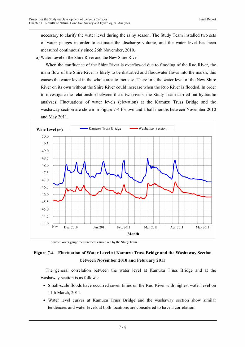
necessary to clarify the water level during the rainy season. The Study Team installed two sets
of water gauges in order to estimate the discharge volume, and the water level has been
measured continuously since 26th November, 2010.
a) Water Level of the Shire River and the New Shire River
When the confluence of the Shire River is overflowed due to flooding of the Ruo River, the
main flow of the Shire River is likely to be disturbed and floodwater flows into the marsh; this
causes the water level in the whole area to increase. Therefore, the water level of the New Shire
River on its own without the Shire River could increase when the Ruo River is flooded. In order
to investigate the relationship between these two rivers, the Study Team carried out hydraulic
analyses. Fluctuations of water levels (elevation) at the Kamuzu Truss Bridge and the
washaway section are shown in Figure 7-4 for two and a half months between November 2010
and May 2011.
Source: Water gauge measurement carried out by the Study Team
Figure 7-4 Fluctuation of Water Level at Kamuzu Truss Bridge and the Washaway Section
between November 2010 and February 2011
The general correlation between the water level at Kamuzu Truss Bridge and at the
washaway section is as follows:
• Small-scale floods have occurred seven times on the Ruo River with highest water level on
11th March, 2011.
• Water level curves at Kamuzu Truss Bridge and the washaway section show similar
tendencies and water levels at both locations are considered to have a correlation.
44.0
44.5
45.0
45.5
46.0
46.5
47.0
47.5
48.0
48.5
49.0
49.5
50.0
11 12 12 12 12 12 1 1 1 1 2 2 2 2 3 3 3 3 4 4 4 4 4 5 5 5
Wate Level (m)
Month
Kamuzu Truss Bridge Washaway Section
Dec. 2010 Nov. Feb. 2011 Mar. 2011 Apr. 2011 May 2011 Jan. 2011
Project for the Study on Development of the Sena Corridor Final Report
Chapter 7 Results of Natural Condition Survey and Hydrological Analyses
7 - 9
• The water level at Kamuzu Truss Bridge fluctuates between 46.7 m and 48.5 m, while the
water level at the washaway section is lower between 45.5 m and 46.9m.
• Difference of water levels at both observation points are between 0.9 m and 1.8 m, and the
average is 1.2 m.
As a result, it can make hydrological analyses at the washaway section based on the water
level observation results at the washaway section.
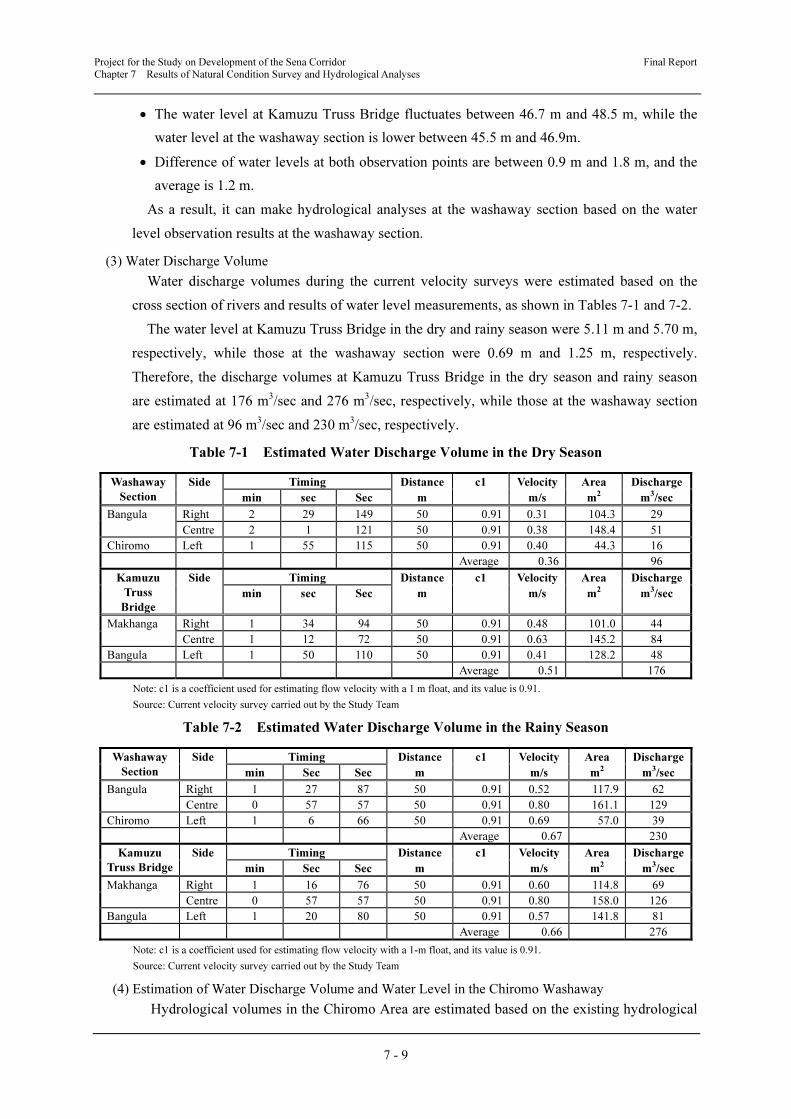
(3) Water Discharge Volume
Water discharge volumes during the current velocity surveys were estimated based on the
cross section of rivers and results of water level measurements, as shown in Tables 7-1 and 7-2.
The water level at Kamuzu Truss Bridge in the dry and rainy season were 5.11 m and 5.70 m,
respectively, while those at the washaway section were 0.69 m and 1.25 m, respectively.
Therefore, the discharge volumes at Kamuzu Truss Bridge in the dry season and rainy season
are estimated at 176 m3/sec and 276 m
3/sec, respectively, while those at the washaway section
are estimated at 96 m3/sec and 230 m
3/sec, respectively.
Table 7-1 Estimated Water Discharge Volume in the Dry Season
Washaway
Section
Side Timing Distance c1 Velocity Area Discharge
min sec Sec m m/s m2 m
3/sec
Bangula Right 2 29 149 50 0.91 0.31 104.3 29
Centre 2 1 121 50 0.91 0.38 148.4 51
Chiromo Left 1 55 115 50 0.91 0.40 44.3 16
Average 0.36 96
Kamuzu
Truss
Bridge
Side Timing Distance c1 Velocity Area Discharge
min sec Sec m m/s m2 m
3/sec
Makhanga Right 1 34 94 50 0.91 0.48 101.0 44
Centre 1 12 72 50 0.91 0.63 145.2 84
Bangula Left 1 50 110 50 0.91 0.41 128.2 48
Average 0.51 176
Note: c1 is a coefficient used for estimating flow velocity with a 1 m float, and its value is 0.91.
Source: Current velocity survey carried out by the Study Team
Table 7-2 Estimated Water Discharge Volume in the Rainy Season
Washaway
Section
Side Timing Distance c1 Velocity Area Discharge
min Sec Sec m m/s m2 m
3/sec
Bangula Right 1 27 87 50 0.91 0.52 117.9 62
Centre 0 57 57 50 0.91 0.80 161.1 129
Chiromo Left 1 6 66 50 0.91 0.69 57.0 39
Average 0.67 230
Kamuzu
Truss Bridge
Side Timing Distance c1 Velocity Area Discharge
min Sec Sec m m/s m2 m
3/sec
Makhanga Right 1 16 76 50 0.91 0.60 114.8 69
Centre 0 57 57 50 0.91 0.80 158.0 126
Bangula Left 1 20 80 50 0.91 0.57 141.8 81
Average 0.66 276
Note: c1 is a coefficient used for estimating flow velocity with a 1-m float, and its value is 0.91.
Source: Current velocity survey carried out by the Study Team
(4) Estimation of Water Discharge Volume and Water Level in the Chiromo Washaway
Hydrological volumes in the Chiromo Area are estimated based on the existing hydrological

Project for the Study on Development of the Sena Corridor Final Report
Chapter 7 Results of Natural Condition Survey and Hydrological Analyses
7 - 10
observation records (discharge volume for the last 39 years and water level for the last 39
years), results of current velocity surveys and water level measurements (see Figure 7-5).
a) Kamuzu Truss Bridge
According to the existing observation data, the past maximum discharge volume did not
exceed 1,500 m3/sec, while the past maximum water level was recorded as 49.599 m in 2005.
Before 1997 when the washaway occurred, the maximum water level was between 47.1 m and
48.5 m. However, after 1997, the maximum water level exceeded 49.0 m almost every year.
b) New Shire River
Even though there is no existing observation data of discharge volume, it is possible to
estimate the water level and discharge volume based on the results of water level measurements
since November 2010 and existing hydrological data at Kamuzu Truss Bridge for the last 39
years.
c) Water Level
Since the water level at the washaway section is estimated by correlation with the water level
at Kamuzu Truss Bridge, based on limited observation records, the highest water level during
floods can be estimated by referring to the water level at Kamuzu Truss Bridge.
According to the results of analyses, difference of water levels at the washaway section and
Kamuzu Truss Bridge is between 0.9 m and 1.8 m (lower at the washaway section), and the
average difference is 1.2 m.
Source: MoIWR
Figure 7-5 Annual Maximum Water Level and Maximum Water Quantity at Kamuzu Truss
Bridge
d) Water Discharge Volume
Since the past maximum discharge volume did not exceed 1,500 m3/sec and the floods on the
Ruo River continue for a long time, the planned maximum discharge volume as a peak
44.0
45.0
46.0
47.0
48.0
49.0
50.0
1971 1973 1975 1977 1979 1981 1983 1985 1987 1989 1991 1993 1995 1997 1999 2001 2003 2005 2007 2009
Year
Maximum Water Level (m)
0
200
400
600
800
1000
1200
1400
1600
Maximum Water Quantity
(m3/s)
Maximu Water Level
Water Quantity max
Project for the Study on Development of the Sena Corridor Final Report
Chapter 7 Results of Natural Condition Survey and Hydrological Analyses
7 - 11
discharge volume can be considered to be the same as the maximum discharge volume at
Kamuzu Truss Bridge.
Based on the analysis results described above, the planned HWL during flooding at the
washaway section is estimated as 48.4 m.
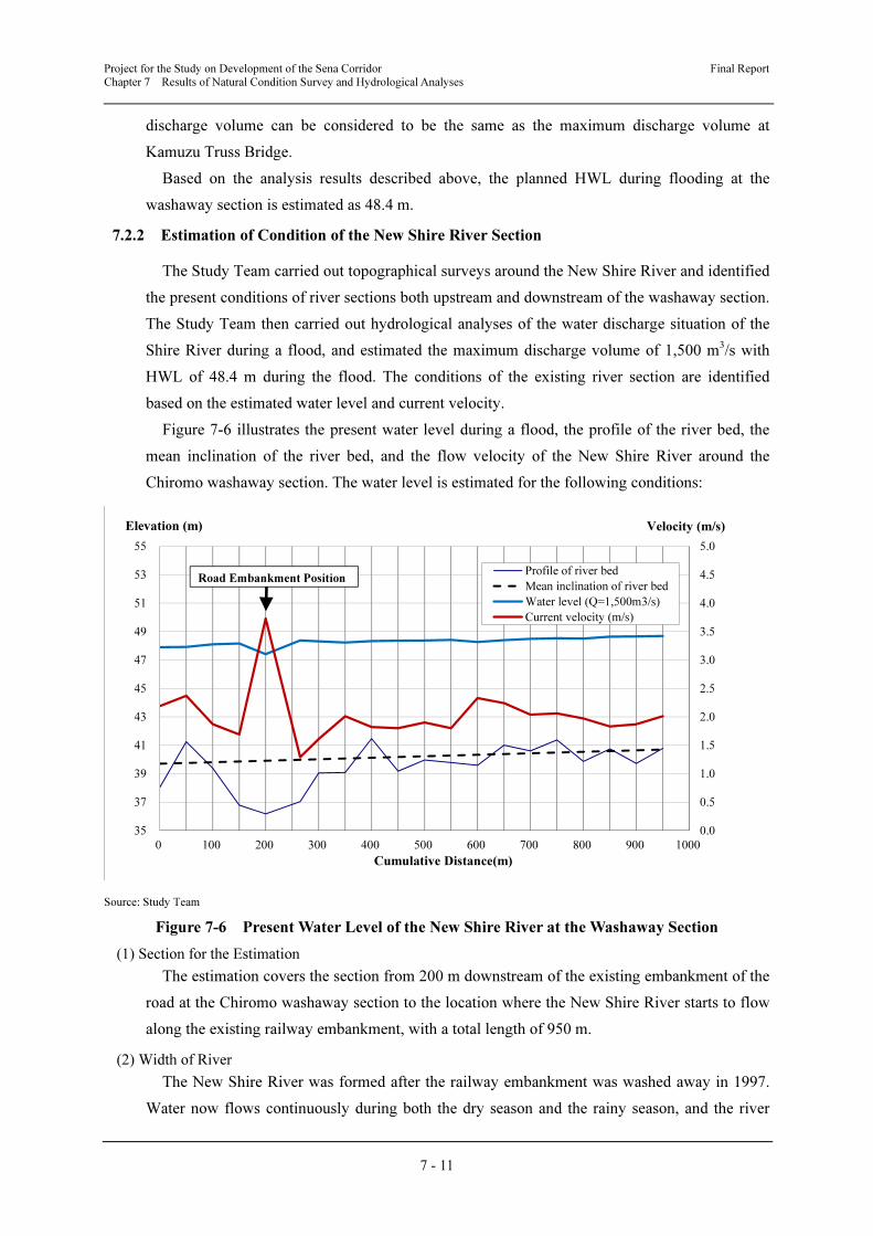
7.2.2 Estimation of Condition of the New Shire River Section
The Study Team carried out topographical surveys around the New Shire River and identified
the present conditions of river sections both upstream and downstream of the washaway section.
The Study Team then carried out hydrological analyses of the water discharge situation of the
Shire River during a flood, and estimated the maximum discharge volume of 1,500 m3/s with
HWL of 48.4 m during the flood. The conditions of the existing river section are identified
based on the estimated water level and current velocity.
Figure 7-6 illustrates the present water level during a flood, the profile of the river bed, the
mean inclination of the river bed, and the flow velocity of the New Shire River around the
Chiromo washaway section. The water level is estimated for the following conditions:
Source: Study Team
Figure 7-6 Present Water Level of the New Shire River at the Washaway Section
(1) Section for the Estimation
The estimation covers the section from 200 m downstream of the existing embankment of the
road at the Chiromo washaway section to the location where the New Shire River starts to flow
along the existing railway embankment, with a total length of 950 m.
(2) Width of River
The New Shire River was formed after the railway embankment was washed away in 1997.
Water now flows continuously during both the dry season and the rainy season, and the river
0.0
0.5
1.0
1.5
2.0
2.5
3.0
3.5
4.0
4.5
5.0
35
37
39
41
43
45
47
49
51
53
55
0 100 200 300 400 500 600 700 800 900 1000
Elevation (m)
Cumulative Distance(m)
Profile of river bed
Mean inclination of river bed
Water level (Q=1,500m3/s)
Current velocity (m/s)
Road Embankment Position
Velocity (m/s)
Project for the Study on Development of the Sena Corridor Final Report
Chapter 7 Results of Natural Condition Survey and Hydrological Analyses
7 - 12
course has become clear.
During a flood, the water level rises because of the increased discharge volume which is
discharged by a wider river width than the normal situation, if there is no obstacle that limits an
increase in river width. However, if any obstacle stops the river from becoming wider, the water
level at the upstream increases due to insufficient discharge capacity of the river section, and the
increased flow velocity causes scouring of the river section which is formed by sedimentation of
soil. Therefore, it is necessary to confirm the existence of any obstacles that would prevent an
increase of river width for the sections of the New Shire River that do not usually have any
problem, in order to estimate the river width during a flood.
a) Course of the River Section
Normally, the New Shire River discharges into the very wide and flat Elephant Marsh, flows
along the railway embankment at the upstream side, and then changes direction at right angles
at the edge of the Chiromo washaway section of the railway embankment and discharges to the
downstream side.
b) Restrictions
The present conditions of the following three river sections, where hydraulic restrictions
might occur during a flood of the New Shire River, are analysed.
1) Upper-most section of the New Shire River
The New Shire River, which has separated from the right bank of the Shire River, discharges
freely in the marsh when the water level rises, since there are no topographical restrictions.
2) Section between Upstream and the Edge of Collapsed Railway Embankment
The New Shire River is forced to discharge along the railway embankment in this section. At
times of low water level, it discharges only at the foot of the railway embankment, and the river
can become wider toward the marsh side, as there are no restrictions on widening of the flow.
3) Section between the Edge of Collapsed Railway Embankment and Downstream
The width of the New Shire River is first controlled by collapsed railway embankments on
both sides of the washaway section (width of about 300 m), then further controlled by a road
embankment on the Bangula side located just downstream from the railway embankment. After
this section, water discharges freely towards the downstream following the river route of the
river section formed by the major washaway.
c) River Width during a Flood
Based on the results of analysing hydraulic restrictions for the river section of the New Shire
River during a flood, hydraulic restrictions to the discharge of flood water were identified at two
river sections in the section between the edge of the collapsed railway embankment and
downstream.
Within these two narrow river width sections, the narrowest section is related to the road
embankment on the Bangula side, and spot-scouring of river sections as well as collapse of
embankment are considered, because the flow from upstream to downstream is highly restricted

Project for the Study on Development of the Sena Corridor Final Report
Chapter 7 Results of Natural Condition Survey and Hydrological Analyses
7 - 13
during a flood. This road embankment was built together with three box culverts in December
2004, in order to connect the washaway section after the major collapse of the railway
embankment in 1997. This road embankment will be a useless structure after a new bridge is
constructed.
Therefore, it is estimated that water discharges over a width of about 200 m during a flood, in
view of the area of railway embankment collision and river section, assuming that the road
embankment does not exist.
(3) Condition of River Section and Inclination of River Bed
The deepest elevation of the river bed along the railway embankment is estimated to be
between 39 m and 41 m without local deep scouring of the river bed, based on the cross section
of the river section of the New Shire River. However, from the edge of the collapsed railway
embankment with almost a right-angled bend, the river bed is deeply scoured and it is deepest
with 36 m at the river section where the road embankment exists. After this river section, the
river bed returns to 39 m to 41 m elevation without local deep scouring of the river bed. The
main cause of this deep erosion is considered to be the river section with a narrow channel. The
average river bed grade is estimated as 1/950, except at the deepest river bed section.
(4) Downstream Water Level
The downstream water level of elevation 47.9 m with a design discharge volume of 1,500
m3/s is used for estimating the river section of the New Shire River. This water level is
calculated under the condition of uniform flow on the average river bed grade.
(5) Roughness Coefficient in the River Section
The roughness coefficient of a river section means the resistance to discharge of river flow,
and its value is determined by conditions such as the shape of the river section, materials of the
river bed, vegetation, etc. Experimental values of this roughness coefficient are available as the
N-value of Manning’s Formula classified according to the conditions of the whole river section.
The Shire River flows into the wide Elephant Marsh and the huge volume of silty material
transported from upstream forms the river bed as sedimentation of the materials occurs. The
grade of the river channel is gentle, there is no large-scale meandering, and the flow route is
almost straight. Therefore, the conditions of “large-scale channel”, “sandy river bed”, and
“channel with limited meandering (n = 0.018 – 0.035)” are considered, and so a roughness
coefficient of 0.035 is used for calculation.
(6) Results of Calculation
a) Water Level
The design highest water level at the location of the planned bridge sites ranges from
47.4 m to 48.4 m, as shown in Figure 7-7 and below the maximum HWL of 48.4 m. The
water level at the narrowed channel caused by the road embankment is 47.4 m, which is 1.0
m below the designed water level, while the water level at the collapsed railway
embankment, just upstream, increases to 48.4 m, 1.0 m higher than the narrowed channel

Project for the Study on Development of the Sena Corridor Final Report
Chapter 7 Results of Natural Condition Survey and Hydrological Analyses
7 - 14
section. The water level of the upstream section from the locations of the planned bridges
ranges from 48.2 m to 48.7 m and the grade of river surface during a flood is almost the
same as the river bed grade with gentle river flow.
b) Current Velocity
The current velocity of the New Shire River during steady flow ranges from 1.3 to 3.7
m/s at the locations of planned bridges and is fastest where the channel section narrows due
to the road embankment. The current velocity upstream of the collapsed railway
embankment ranges from 1.6 to 2.3 m/s and the river flows gently, except at the narrowed
channel section.
The river section of the New Shire River, which discharges into Elephant Marsh, is
formed by sedimentation of silty material. When the current velocity increases, fine silty
sediment is easily moved by the attractive force of the river flow, and so local scouring of
the river section is likely to continue.
Source: Study Team
Figure 7-7 Designed Water Level of the New Shire River at the Chiromo Washaway Section
7.2.3 Plan for Protecting the River Section
The Study Team has considered plans to construct two bridges at the Chiromo washaway
section of the New Shire River. Hence, it is desirable to secure a smooth flow of flood water
at river sections after constructing these two bridges.
(1) Major Issue
The elevation of the top of the road embankment on the Bangula side is about 49.0 m and
the distance between the edge of the road embankment and the boat landing place on the
0.0
0.5
1.0
1.5
2.0
2.5
3.0
3.5
4.0
4.5
5.0
35
37
39
41
43
45
47
49
51
53
55
0 100 200 300 400 500 600 700 800 900 1000
Velocity (m/s)Elevation (m)
Cumulative Distance (m)
Profile of river bed
Mean inclination of river bed
Water level (Q=1,500m3/s)
Current velocity (m/s)
Road Embankment Position

Project for the Study on Development of the Sena Corridor Final Report
Chapter 7 Results of Natural Condition Survey and Hydrological Analyses
7 - 15
Makhanga side is very narrow, with only about 60 m. This narrow channel can obstruct
water discharge because the current velocity is 3.7 m/s, about twice as fast as the upstream
and downstream sides.
If there is a channel with variations between upstream and downstream of a river, this is a
major cause of local scouring at the centre of the river section due to the restricted river
width.
If this narrow channel remains in the future, further erosion of the river section will
continue and possibly cause the river bank to collapse. Hence, this problem must be solved.
(2) Countermeasures
Based on the results of a hydraulic analysis assuming that the entire road embankment on the
Bangula side is demolished and a part of the river section is excavated (see Figure 11-8), the
current velocity is estimated to decrease to about 2.0 m/s if sufficient river section is secured
with the river bed elevation of about 45.0 m.
In this case, it is necessary to protect the excavated river bed by installing gabions (1×2×0.5
m) to protect the whole excavated area. Also, it is necessary to conduct the minimum-scale
improvement of the river section in consideration of the condition of the New Shire River, in
order to maintain river sections between newly installed abutments and piers of the planned
bridges.
Source: Study Team
Figure 7-8 Plan for Improving the River Section at the Narrowed Channel Section
(3) Plan for Improving the River Section
The New Shire River is characterized by: 1) variation of discharge volume between the rainy
season and dry season, and 2) increase of water level in the rainy season caused by the Ruo
34
36
38
40
42
44
46
48
50
52
0 50 100 150 200 250
Elevation (m)
River Width (m)
Designed river cross section
Actual river cross section
WL (Actual)
WL (Designed)

Project for the Study on Development of the Sena Corridor Final Report
Chapter 7 Results of Natural Condition Survey and Hydrological Analyses
7 - 16
River. In general, it is possible to design a river cross section to vary in width according to
variations in water quantity. This means that the low flow channel with narrow river width is
used to discharge water during the dry season when there is less water, while the river cross
section above the high water channel is used to discharge flood water during the rainy season.
This approach is called “multiple river cross sections.” In this analysis, a preliminary study was
carried out for multiple river cross sections and standard types of revetments.
a) Chiromo Washaway Section
1) River Width
It is estimated that the river width will be about 220 m during a flood after demolishing the
road embankment at the narrow channel, with a current velocity of 2 m/s. Since the water level
during the normal situation in the rainy season is an elevation of about 46 m, the width of the
low flow channel is sufficient within the existing narrow channel of 60 m. Therefore, the high
water channel is determined to prevent an increase of excessive current velocity during a flood.
2) River Cross Section
The water level of the New Shire River falls to an elevation of about 45 m during the dry
season, increases to 46 m in the rainy season, and increases to 48 m when a flood occurs caused
by the Ruo River. The elevation of a high water channel is normally determined to allow
inundation several times a year or once every two years with the annual maximum water
discharge volume. Based on the records of water level readings at the washaway section, the
maximum water level in 2011 was 46.9 m. Hence, the high water channel is set with an
elevation of 47 m.
3) Gradient of Embankment Slope
The gradient of the embankment slope is estimated to be 1:2.0.
4) Revetment Works
For structures planned in the Study, revetments for both the low flow channel to protect the
low flow channel bank and for the high water channel to protect the embankment at times of
HWL are necessary.
i) Revetment for high water channel (Type A)
The river flow will directly affect the abutments and piers of constructed road and railway
bridges below the HWL. Even though the current velocity is about 2 m/s, the velocity around
structures is not uniform and whirlpools could form. Hence, it is necessary to install minimum
revetments using mat-shaped gabions in stepped placing (see Figure 7-9). The area for installing
revetments is planned to be about 30 m from the position of an abutment on both sides, as the
minimum required to protect the embankment around an abutment. This type of revetment is
also planned to be installed beside the piers of bridges to protect against the incoming flow of
water to prevent scouring of the foundations of piers, covering an area about three times wider
than the side width of piers.

Project for the Study on Development of the Sena Corridor Final Report
Chapter 7 Results of Natural Condition Survey and Hydrological Analyses
7 - 17
Source: Study Team
Figure 7-9 Typical Cross Section of River Protection Work for the New Shire River (Type A)
ii) Revetment for low flow channel (Type B)
The revetment for the low flow channel is designed to protect the banks of the river when the
water level is low. Since the velocity of steady flow is about 2 m/s, it is planned to place mat
shaped gabions on flat ground to prevent local scouring at the foot of the river bank. The area
over which the revetment is planned to be placed is 100 m from the edge of the abutment on
both sides (see Figure 7-10).
Source: Study Team
Figure 7-10 Typical Cross Section of River Protection Work for the New Shire River (Type B)
b) Railway Embankment
1) Width of the River
Since the right side of the New Shire River along the railway embankment is the flat marsh,
flood water spreads into the marsh and is discharged with uncontrolled width. The current
velocity at this part of the river is about 2 m/s at present. Therefore, flood water is estimated to
mainly discharge along the water route with a river width of about 200 m.
2) River cross section
The elevation of the top of the railway embankment is about 50 m and the width of the top of
the embankment is about 4.0 m. The slope gradient of the embankment is 1:2.0 and the
embankment is stable, except in sections that have been partly scoured.
However, the New Shire River constantly flows along the railway embankment and so the
foot of the embankment, which is part of its foundation, is likely to be gradually scoured,
because this part of the embankment is part of the river section subject to discharge. Also, the

Project for the Study on Development of the Sena Corridor Final Report
Chapter 7 Results of Natural Condition Survey and Hydrological Analyses
7 - 18
edge of the collapsed embankment has receded towards Makhanga caused by erosion at the
edge of the collapsed embankment, because the water route turns almost at right angles at this
point.
Since this embankment serves as the bank of the New Shire River, it is necessary to carry out
measures, the same as for an ordinary river bank.
3) Gradient of Railway Embankment Slope
The gradient of the embankment slope is estimated as 1:2.0.
4) Revetment Works (Type C)
Foot protection works are planned to be taken as countermeasures to control scouring of the
foot of the railway embankment, which is the right-side bank of the New Shire River. Foot
protection works will be performed with revetment by riprap, involving throwing rock material
such as round stones into the foot of the embankment up to the high water channel level of
elevation of 47 m. The width of the revetment is planned to be about 4 m with a slope gradient
of 1:2.0. Round stones are available from those rivers across S152 (see Figure 7-11).
It is planned to apply this foot protection works between the location where the New Shire
River collides with the railway embankment and the existing landing point of boats, including
the edge of the collapsed railway embankment on the Makhanga side.
Source: Study Team
Figure 7-11 Typical Cross Section of River Protection Work for the New Shire River (Type C)
7.2.4 Hydraulic Analyses for Road Improvement Plan
In order to identify HWL of the area for the road and railway improvement plans, hydraulic
analyses were carried out to determine HWL at certain points along the improvement sections
based on records of water gauge readings at the Shire River and the New Shire River. Note that
HWL of the section between Makhanga and the Shire River is estimated based on interviews
with local residents about their experiences of floods in the past.
Figure 7-12 shows estimated HWL at six points.

Project for the Study on Development of the Sena Corridor Final Report
Chapter 7 Results of Natural Condition Survey and Hydrological Analyses
7 - 19
Source: Study Team
Figure 7-12 Estimated HWL for the Area between Chiromo Washway and the Makhanga
CHAPTER 8
PRE-FEASIBILITY STUDY ON
RECONSTRUCTION OF
S151 ROAD BETWEEN
MAKHANGA AND BANGULA

Project for the Study on Development on the Sena Corridor Final Report
Chapter 8 Pre-Feasibility Study on Reconstruction of S151 Road between Makhanga and Bangula
8 - 1
Chapter 8 Pre-Feasibility Study on Reconstruction of S151 Road between
Makhanga and Bangula
8.1 Justification of Reconstruction of S151 between Makhanga and Bangula
In the Master Plan study, reconstruction of S151 between Makhanga and Bangula was
selected as the first priority project in the short- and medium-term programme. Before the major
washaway at Chiromo in 1997, there was a paved road between Makhanga and Bangula and
vehicles travelling on this road section enabled people to take agricultural products from the
western side of the Shire River to the market in Bangula. After the washaway, the road was cut
completely and people must now cross the river by boat to take their products to Bangula, which
is expensive. This situation has a large negative impact on the local economy and lives of the
local residents, particularly those living on the eastern side of the Shire River.
RA has already signed a contract with a contractor to upgrade S151 between Thyolo and
Makhanga and construction works are expected to commence soon. After this section of S151
has been upgraded, the arterial road network in the Southern Region will be complete, except
for a gap between Makhanga and Bangula. S151 can then serve as an alternative to M1, which
is currently the only arterial road connecting the Lower Shire area and Blantyre.
Under these circumstances, the Study Team considers that carrying out the Pre-F/S for the
reconstruction of S151 between Makhanga and Bangula is justified.
8.2 Preliminary Design
8.2.1 Preliminary Design of Road Section between Makhanga and Bangula
(1) Upgrading Concept of the Design Road
The S151 Road is one of the routes which form the primary road network in Malawi. From
the view point of improving road functions of S151, most important requirements for upgrading
concept are to secure safe and reliable traffic throughout the year in accordance with not only
the Malawi highway standards but the needs and conditions in the target area. Therefore, the
upgrading concept of the S151 Road is to build a two-lane paved road which will not be flooded
in the rainy season. The required height of the raised road should be determined considering
expected flood levels. The estimated raising height of S151 road is at 2.3 m on average for the
total projected extension.
(2) Alignment Selection Process
The Study Team selected the proposed road alignment of the project by dividing it into the
following two sections (see Figure 8-1).
• Section A: Outside Makhanga Village (L = 6 km) [3 alternatives]
• Section B: In Makhanga Village (L = 3 km) [3 alternatives]

Project for the Study on Development on the Sena Corridor Final Report
Chapter 8 Pre-Feasibility Study on Reconstruction of S151 Road between Makhanga and Bangula
8 - 2
Source: Study Team
Figure 8-1 Section Map for the Alignment Plan
a) Road Alignment outside Makhanga Village (Section A)
Road alignment should be determined considering various factors such as natural conditions
(hydrology, geography, geology, etc.), land use (agriculture, resident, marsh, etc.), infrastructure
(road, railway, lifeline, etc.) and living environment (traffic factor, safety, accessibility,
landscape, etc.).
The Study Team conducted a comparison of the following three alternatives regarding where
the raised road should be built in Section A. As a result of the comparison, Alternative 1 is more
advantageous in terms of i) measures for ground stabilization and ii) construction cost. (see
Table 8-1)
Alternative 1: Existing Road Alignment
Alternative 2: Between the Existing Road and the Railway Line
Alternative 3: Railway Line Alignment (Integrated Embankment of Road and Railway)
Table 8-1 Road Alignment outside Makhanga Village (Section A)
Section A: Outside Makhanga Village (L = 6 km)
Alternative
1 2 3
Existing Road Alignment Between the Existing Road and
the Railway Line
Railway Line Alignment
(Integrated Embankment of
Road and Railway)
Measures for
Ground
Stabilization
Slow filling could be
required A
Replacement of top soft soil
layer (2m) could be required D
Replacement of top soft soil
layer (2m) could be required D
Influence on
Railway
Embankment
No impact C No impact C
Railway embankment could
need to be rebuilt due to poor
stability
D
Farmland
between road
and railway
Land use could be partially
limited due to road raising C
Land use could be partially
limited due to road raising C Keeping the status quo A
Affected
houses and
shops
No impact or negligible
impact C
No impact or negligible
impact C
No impact or negligible
impact C
Construction
Cost 8.46 US$ million (1.00) A 12.54 US$ million (1.48) D 12.30 US$ million (1.45) D
Evaluation Alternative 1 for Section A is advantageous in terms of i) measures for ground stabilization and ii)
construction cost.
A: High comparative advantage, B: Comparative advantage, C: No comparative advantage, D: Disadvantageous
Note: Construction cost does not include contingency and consultant fee.
Source: Study Team
Section A Section B
Bangula Makhanga
Ruo River
Shire River
New Shire River

Project for the Study on Development on the Sena Corridor Final Report
Chapter 8 Pre-Feasibility Study on Reconstruction of S151 Road between Makhanga and Bangula
8 - 3
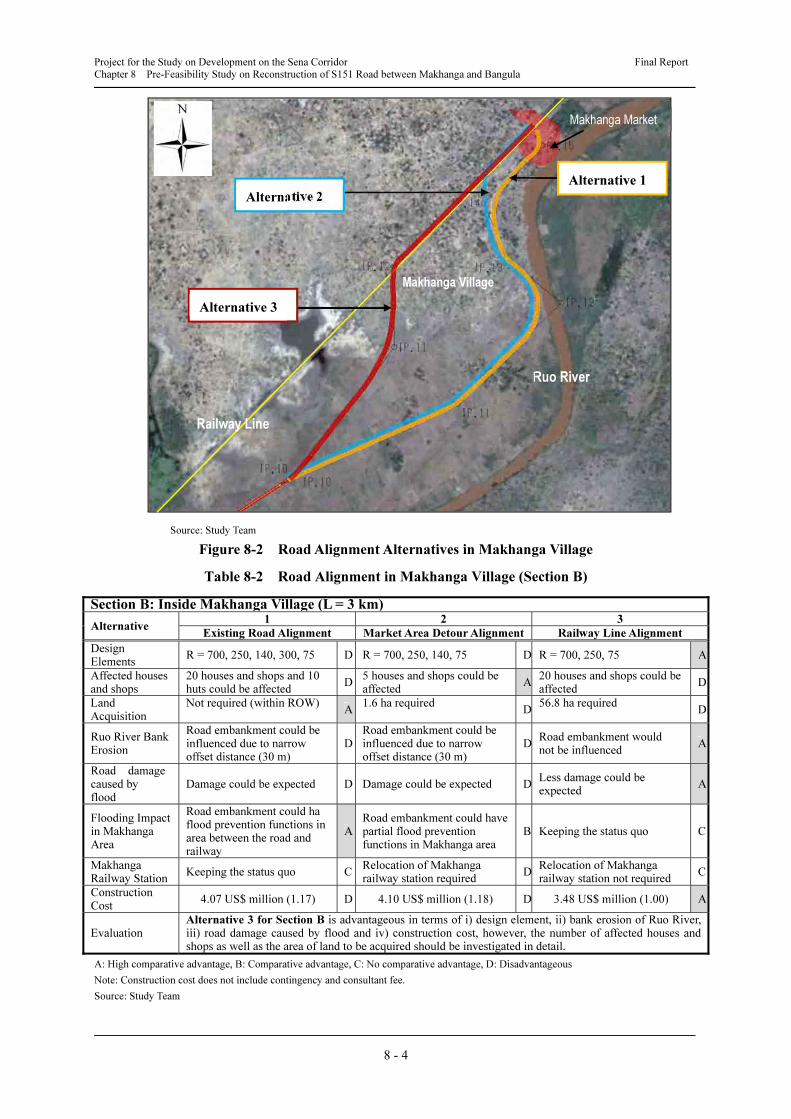
b) Road Alignment in Makhanga Village (Section B)
The following considerations and/or problems are identified in the Makhanga village area
when the raised road is built on the exiting road alignment.
• There is a possibility that at least more than 20 houses and shops and 10 huts in the market
area around the level crossing with railway could be relocated.(see Photo 8-1)
• There is a possibility that the progressing erosion along the right bank of the Ruo River
could influence the S151 road in the future, especially, the section with only 30 m distance
between the S151 road and the Ruo River. (see Photo 8-2)
•
Photo by Study Team, November 2011
Photo 8-1 Makhanga Market Area
Photo 8-2 Bank Erosion of the Ruo River
Thus, the Study Team conducted a comparison of the following three alternatives in
Makhanga area.
Alternative 1: Existing Road Alignment
Alternative 2: Market Area Detour Alignment
Alternative 3: Railway Line Alignment
As a result of the comparison, Alternative 3 is most advantageous in terms of i) design
element, ii) the Ruo River bank erosion, iii) road damage caused by flood and iv) construction
cost. However, further examinations for selecting the final alignment is recommended for the
following reasons. (see Figure 8-2 and Table 8-2)
• To clarify and grasp the location and number of houses, shops and public facilities along the
railway in order to set the road alignment and location of level crossings across the railway,
and then to obtain social consensus.
• To clarify and grasp geological conditions in detail on the planned alignment.
• To clarify and grasp the erosion mechanism of the Ruo River bank in order to justify
realignment of the road.
Project for the Study on Development on the Sena Corridor Final Report
Chapter 8 Pre-Feasibility Study on Reconstruction of S151 Road between Makhanga and Bangula
8 - 4
Source: Study Team
Figure 8-2 Road Alignment Alternatives in Makhanga Village
Table 8-2 Road Alignment in Makhanga Village (Section B)
Section B: Inside Makhanga Village (L = 3 km)
Alternative 1 2 3
Existing Road Alignment Market Area Detour Alignment Railway Line Alignment
Design Elements
R = 700, 250, 140, 300, 75 D R = 700, 250, 140, 75 D R = 700, 250, 75 A
Affected houses and shops
20 houses and shops and 10 huts could be affected
D5 houses and shops could be affected
A20 houses and shops could be affected
D
Land Acquisition
Not required (within ROW) A
1.6 ha requiredD
56.8 ha required D
Ruo River Bank Erosion
Road embankment could be influenced due to narrow offset distance (30 m)
DRoad embankment could be influenced due to narrow offset distance (30 m)
DRoad embankment would not be influenced
A
Road damage caused by flood
Damage could be expected D Damage could be expected DLess damage could be expected
A
Flooding Impact in Makhanga Area
Road embankment could ha flood prevention functions in area between the road and railway
ARoad embankment could have partial flood prevention functions in Makhanga area
B Keeping the status quo C
Makhanga Railway Station
Keeping the status quo CRelocation of Makhanga railway station required
DRelocation of Makhanga railway station not required
C
Construction Cost
4.07 US$ million (1.17) D 4.10 US$ million (1.18) D 3.48 US$ million (1.00) A
Evaluation Alternative 3 for Section B is advantageous in terms of i) design element, ii) bank erosion of Ruo River, iii) road damage caused by flood and iv) construction cost, however, the number of affected houses and shops as well as the area of land to be acquired should be investigated in detail.
A: High comparative advantage, B: Comparative advantage, C: No comparative advantage, D: Disadvantageous
Note: Construction cost does not include contingency and consultant fee.
Source: Study Team
Makhanga Market
Alternative 1
Alternative 2
Alternative 3
Railway Line
Ruo River
Makhanga Village

Project for the Study on Development on the Sena Corridor Final Report
Chapter 8 Pre-Feasibility Study on Reconstruction of S151 Road between Makhanga and Bangula
8 - 5
c) Considerations for the Section of the Railway Level Crossing in Makhanga
• A crossing angle with the railway line of more than 45° is stipulated in order to provide
adequate visibility and safety to traffic.
• Comparing Alternative 3-A and 3-B, the former is advantageous in terms of road alignment
the latter is used for a minimum continuous curve radius of 75 m at the level crossing point.
(see Figure 8-3)
• Makhanga Railway Station is required the length along the railway of 505 m to rehabilitate
and establish station facilities. If less than 505 m, the station could be relocated in the
eastern direction (Sandama side).
Source: Study Team
Figure 8-3 Alignment at the Level Crossing Point
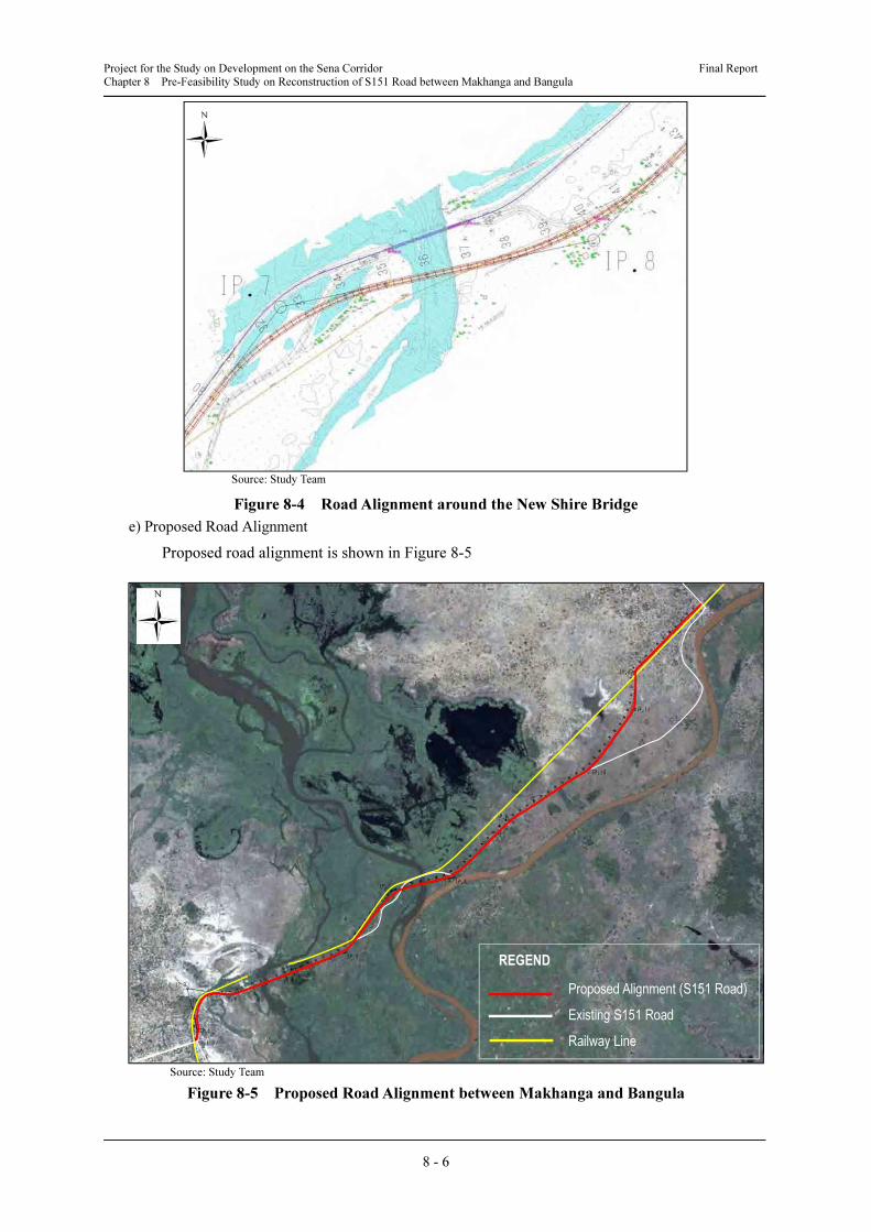
d) Considerations for the Section of the Shire River Crossing
The existing Kamuzu Truss Bridge only provides traffic services across the Shire River
presently. This combined rail-road bridge only has one lane on the road due to the narrow width.
Thus, in line with the upgrade plan of S151 in the Master Plan, a new road bridge with two
lanes across the Shire River instead of the existing Kamuzu Truss Bridge will be constructed in
order to establish a two-way paved road between Thyolo and Bangula.
The existing alignment of approach roads to the Kamuzu Truss Bridge is composed by an 80
m radius curve. The Study Team proposes that new alignment around the New Shire Bridge be
improved corresponding to the design speed of 80 km/h considering location of the planned
bridge and topographical conditions. This makes a substantial improvement on the existing
alignment of approach roads (curve radius of 700 m and 900 m) (see Figure 8-4).
Alternative 3-A
Alternative 3-B
Project for the Study on Development on the Sena Corridor Final Report
Chapter 8 Pre-Feasibility Study on Reconstruction of S151 Road between Makhanga and Bangula
8 - 6
Source: Study Team
Figure 8-4 Road Alignment around the New Shire Bridge
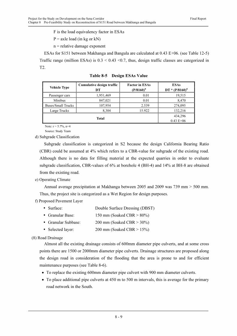
e) Proposed Road Alignment
Proposed road alignment is shown in Figure 8-5
Source: Study Team
Figure 8-5 Proposed Road Alignment between Makhanga and Bangula
Proposed Alignment (S151 Road)
Existing S151 Road
Railway Line
REGEND

Project for the Study on Development on the Sena Corridor Final Report
Chapter 8 Pre-Feasibility Study on Reconstruction of S151 Road between Makhanga and Bangula
8 - 7
(3) Design Speed
According to Design Report of Thyolo – Makwasa – Thekerani – Muona – Bangula Road
Project (Upgrading of S151), a design speed between Thyolo and Makhanga was proposed at 60
km/h for the rolling terrain and 50 km/h for the mountain terrain. The design speed based on the
existing alignment between Makhanga and Bangula is estimated at 30 km/h to 60 km/h.
The proposed design speed for the project site between Makhanga and Bangula is 80 km/h
considering the plan for a new railway bridge at the Chiromo washaway section which was
washed away, as well as a plan for a new road bridge around the confluence of the Shire River
and the Ruo River in terms of economic efficiency.
On the other hand, the road runs through a market and/or residential area and there is a level
crossing across the railway in Makhanga village. The design speed in Makhanga village area is
proposed at 30 km to 60 km in order to mitigate relocation of houses and shops and securing
safe traffic.
• Design Speed: 80 km/h
• Village area and section of level crossing with railway: 30 km/h to 60 km/h
(4) Road Longitudinal Plan
a) Clearance
• 0.6 m from H.W.L to the road surface of embankment section
• 1.0 m from H.W.L to the bottom of bridge girder
b) Gradients and Vertical Curves
Gradients and vertical curves of the design road are as follows. (see Table 8-3)
Table 8-3 Vertical Alignment
STA. Cumulative
Distance
Vertical
Height
Gradient
(%)
Vertical
Length
Vertical
Curve
0+00 0 49.600 -0.285714 - -
1+40 140 49.200 0.000000 0 0
10+19 1,019 49.200 2.500000 140 5,600
12+63 1,263 55.300 -2.500000 240 4,800
14+91 1,491 49.600 0.000000 140 5,600
32+38 3,238 49.600 2.000000 140 7,000
36+23 3,623 57.300 -2.000000 200 5,000
39+38 3,938 51.000 0.000000 140 7,000
57+70 5,770 51.000 0.176101 0 0
73+60 7,360 53.800 0.009021 0 0
84+68.5 8,468.5 53.900 - - -
Source: Study Team
(5) Cross Section Elements
The total road width is 9.7 m since the design road is categorized as a primary road network.
The width of the carriageway is 6.7 m and the hard-shoulder for both sides is 1.5 m. The
cross-slope of the carriageway and hard-shoulder is 2.5%.
• Road Type: Primary Road (Secondary Road)
• Total Road Width: 9.7 m

Project for the Study on Development on the Sena Corridor Final Report
Chapter 8 Pre-Feasibility Study on Reconstruction of S151 Road between Makhanga and Bangula
8 - 8
• Carriageway: 6.7 m, shoulder: 1.5 m (Left and right)
• Carriageway and shoulder cross slope: 2.5%
(6) Future Traffic Volume
Daily traffic volume in 2030 on S151 between Makhanga and Bangula, which is the targeted
project area, is 1,606 vehicles per day based on traffic demand forecast analysis. Traffic volume
by type of vehicle are summarised as follows. (see Table 8-4)
Table 8-4 Future Traffic Volume in 2030
Route
Section Traffic Volume (vehicle/day)
From To Total Passenger
Cars Minibus Buses
Small
Trucks
Large
Trucks
S151
Seven Thyolo 208 137 44 3 21 3
Makhanga Seven 1,395 927 381 24 54 9
Bangula Makhanga 1,606 1,076 467 30 28 5
Source: Study Team
(7) Pavement Design
a) Design Process
• Estimating the cumulative traffic load expected during the design life
• Defining the strength of subgrade over which the road will be built
• Defining the normal operating climate (wet or dry)
• Determining any practical aspects which influence the design selection
• Selecting possible pavement structure
b) Design Life
According to Southern Africa Transport and Communications Commission (SATCC) code of
practice for the design of road pavements, design life is in the range of 10 to 20 years depending
on the situation. This time, the design life is proposed at 15 years considering data reliability
and the importance of service.
c) Design Traffic Class
The one-directional cumulative traffic flow for each category expected over the design life is
forecasted using the following formula.
100/
1)100/1(365
r
rTDT
p−+
××=
where
DT is the cumulative design traffic in a vehicle category, for one direction
T = average daily traffic in a vehicle category in the first year (one direction)
r = average assumed growth rate, percent per annum
p = design life in years
The following formula is used for converting real axle loads to Equivalent Standard Axles
(ESAs).
F = (P/8160)n
(for loads in kg) or F = (P/80)n
(for loads in kN)
where
Project for the Study on Development on the Sena Corridor Final Report
Chapter 8 Pre-Feasibility Study on Reconstruction of S151 Road between Makhanga and Bangula
8 - 9
F is the load equivalency factor in ESAs
P = axle load (in kg or kN)
n = relative damage exponent
ESAs for S151 between Makhanga and Bangula are calculated at 0.43 E+06. (see Table 12-5)
Traffic range (million ESAs) is 0.3 < 0.43 <0.7, thus, design traffic classes are categorized in
T2.
Table 8-5 Design ESAs Value
Vehicle Type Cumulative design traffic Factor in ESAs ESAs
DT (P/8160)n
DT * (P/8160)n
Passenger cars 1,951,469 0.01 19,515
Minibus 847,021 0.01 8,470
Buses/Small Trucks 107,954 2.539 274,095
Large Trucks 8,304 15.922 132,216
Total 434,296
0.43 E+06
Note: r = 5.7%, n=4
Source: Study Team
d) Subgrade Classification
Subgrade classification is categorized in S2 because the design California Bearing Ratio
(CBR) could be assumed at 4% which refers to a CBR-value for subgrade of the existing road.
Although there is no data for filling material at the expected quarries in order to evaluate
subgrade classification, CBR-values of 6% at borehole 4 (BH-4) and 14% at BH-8 are obtained
from the existing road.
e) Operating Climate
Annual average precipitation at Makhanga between 2005 and 2009 was 739 mm > 500 mm.
Thus, the project site is categorized as a Wet Region for design purposes.
f) Proposed Pavement Layer
� Surface: Double Surface Dressing (DBST)
� Granular Base: 150 mm (Soaked CBR > 80%)
� Granular Subbase: 200 mm (Soaked CBR > 30%)
� Selected layer: 200 mm (Soaked CBR > 15%)
(8) Road Drainage
Almost all the existing drainage consists of 600mm diameter pipe culverts, and at some cross
points there are 1500 or 2000mm diameter pipe culverts. Drainage structures are proposed along
the design road in consideration of the flooding that the area is prone to and for efficient
maintenance purposes (see Table 8-6).
• To replace the existing 600mm diameter pipe culvert with 900 mm diameter culverts.
• To place additional pipe culverts at 450 m to 500 m intervals, this is average for the primary
road network in the South.
Project for the Study on Development on the Sena Corridor Final Report
Chapter 8 Pre-Feasibility Study on Reconstruction of S151 Road between Makhanga and Bangula
8 - 10
Table 8-6 Drainage Construction Plan
Location
Km
Drainage Remarks
Design Existing
0.00 (Bangula) (D x no.) (D x no.)
0.43 PIPE 900 x 1 PIPE 600 x 1
0.60 PIPE 900 x 1 PIPE 600 x 1
0.64 - - PIPE 2000 x 6 No functioning
1.27 BRIDGE - PIPE 5000 x 3 Chiromo Road Bridge
1.79 PIPE 900 x 1 PIPE 600 x 1
2.71 PIPE 900 x 1 PIPE 600 x 1
3.15 PIPE 900 x 1 - - additional
3.60 BRIDGE - BRIDGE Kamuzu Truss Bridge
3.96 PIPE 1500 x 2 PIPE 1500 x 2
4.22 PIPE 900 x 1 - - additional
4.60 PIPE 900 x 1 - - additional
5.00 PIPE 900 x 1 - - additional
5.36 PIPE 900 x 2 PIPE 600 x 2
5.72 PIPE 900 x 1 PIPE 600 x 1
5.80 PIPE 900 x 1 PIPE 600 x 1
6.00 PIPE 900 x 1 - - additional
6.50 PIPE 900 x 1 - - additional
7.00 PIPE 900 x 1 - - additional
7.30 PIPE 900 x 1 - - additional
Source: Study Team
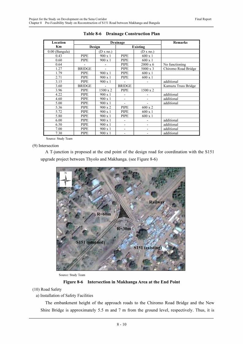
(9) Intersection
A T-junction is proposed at the end point of the design road for coordination with the S151
upgrade project between Thyolo and Makhanga. (see Figure 8-6)
Source: Study Team
Figure 8-6 Intersection in Makhanga Area at the End Point
(10) Road Safety
a) Installation of Safety Facilities
The embankment height of the approach roads to the Chiromo Road Bridge and the New
Shire Bridge is approximately 5.5 m and 7 m from the ground level, respectively. Thus, it is
Railway
S151 (existing)
S151 (planned)
R=60m
R=30m
Project for the Study on Development on the Sena Corridor Final Report
Chapter 8 Pre-Feasibility Study on Reconstruction of S151 Road between Makhanga and Bangula
8 - 11
proposed to install guardrails along both sides of the approach roads of approximately 180 m for
the Chiromo Road Bridge and 300 m for the New Shire Bridge. The guardrails are to be located
on the outside of the 1.5 m shoulders at a recommended marginal width of 1.0 m.
b) Road Signs and Pavement Markings
The following road signs and pavement markings are to be set in appropriate positions:
• Regulatory signs such as speed limits
• Information signs such as to indicate destinations at a proper location
• Danger signs such as at an approach of an intersection, sharp curves and railway level
crossings
• Pavement markings such as centreline and road strips
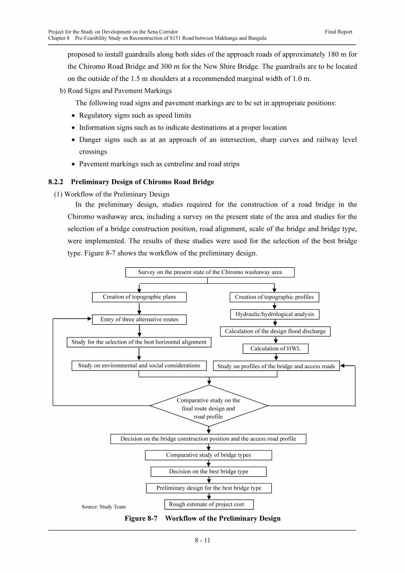
8.2.2 Preliminary Design of Chiromo Road Bridge
(1) Workflow of the Preliminary Design
In the preliminary design, studies required for the construction of a road bridge in the
Chiromo washaway area, including a survey on the present state of the area and studies for the
selection of a bridge construction position, road alignment, scale of the bridge and bridge type,
were implemented. The results of these studies were used for the selection of the best bridge
type. Figure 8-7 shows the workflow of the preliminary design.
Source: Study Team
Figure 8-7 Workflow of the Preliminary Design
Creation of topographic profiles
Entry of three alternative routes
Study for the selection of the best horizontal alignment
Study on environmental and social considerations
Calculation of the design flood discharge
Calculation of HWL
Study on profiles of the bridge and access roads
Comparative study on the
final route design and
road profile
Decision on the bridge construction position and the access road profile
Comparative study of bridge types
Decision on the best bridge type
Hydraulic/hydrological analysis
Preliminary design for the best bridge type
Rough estimate of project cost
Creation of topographic plans
Survey on the present state of the Chiromo washaway area
Project for the Study on Development on the Sena Corridor Final Report
Chapter 8 Pre-Feasibility Study on Reconstruction of S151 Road between Makhanga and Bangula
8 - 12
(2) Present State of the Planned Bridge Construction Position
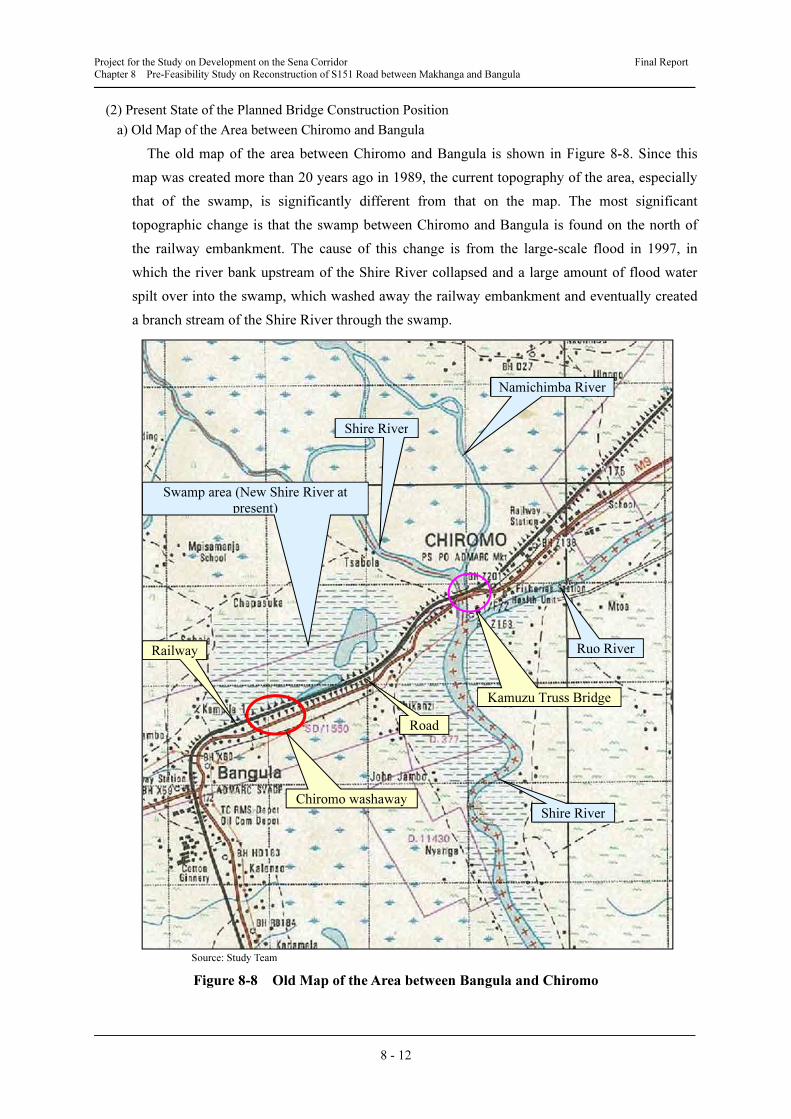
a) Old Map of the Area between Chiromo and Bangula
The old map of the area between Chiromo and Bangula is shown in Figure 8-8. Since this
map was created more than 20 years ago in 1989, the current topography of the area, especially
that of the swamp, is significantly different from that on the map. The most significant
topographic change is that the swamp between Chiromo and Bangula is found on the north of
the railway embankment. The cause of this change is from the large-scale flood in 1997, in
which the river bank upstream of the Shire River collapsed and a large amount of flood water
spilt over into the swamp, which washed away the railway embankment and eventually created
a branch stream of the Shire River through the swamp.
Source: Study Team
Figure 8-8 Old Map of the Area between Bangula and Chiromo
Kamuzu Truss Bridge
Ruo River
Shire River
Shire River
Namichimba River
Railway
Road
Chiromo washaway
Swamp area (New Shire River at
present)

Project for the Study on Development on the Sena Corridor Final Report
Chapter 8 Pre-Feasibility Study on Reconstruction of S151 Road between Makhanga and Bangula
8 - 13
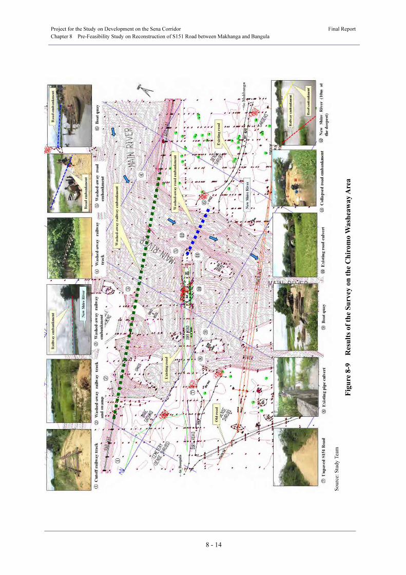
b) Present Status of the Chiromo Washaway
Figure 8-9 shows the results of the survey on the present state of the Chiromo washaway area
where the railway and the road are disrupted as a large number of the railway and road
embankments were washed away in the large-scale flood in 1997. While the length of the
railway embankment washed away was approximately 360 m, only about 100 m of road
embankment was washed away was approximately 100m, of about a quarter of the length of the
washed-away railway embankment. Since the railway embankment had been constructed on the
north side of the road embankment, the railway embankment worked as a river bank and
protected the road embankment from the flood water to some extent during the flood. This is
thought to be why the damage caused by the flood water on the road embankment was smaller
than that on the railway embankment.
(3) Study on the Bridge Construction Position and Access Roads
The best bridge construction position shall be selected among the three alternatives
mentioned below using the results of a comparative study on the bridge construction positions
and access roads of the three alternatives. In the comparison, the three alternatives shall be
analysed comprehensively, with bridge length, cost efficiency, alignment of the access roads,
impact on the access roads to the New Shire River, flood control measures, land acquisition,
construction efficiency and impact on the natural and social environments taken into full
consideration, and the best alternative shall be identified from the results of the analysis.
a) Alternative 1 (Use the existing road)
While more than 360 m of the railway embankment on the Bangula side was washed away,
the length of the washed away road embankment was less than 100m. Alternative 1 is to make
the most of the remaining road embankment on the Bangula side. Since the bridge in this
alternative is significantly affected by the New Shire River when it floods, a survey shall be
implemented to study and confirm the condition of the river.
b) Alternative 2 (The best alignment)
Since Alternative 1 makes the most of the existing road, there shall be an S-shaped section on
the access road on the Makhanga side of the new bridge. This is an alternative to connect the
Bangula side and the Makhanga side of the existing road with a straight route without an
S-shaped section.
c) Alternative 3 (Use the old road as a detour route)
This is an alternative to construct a new road which makes a large detour to the south of the
Chiromo washaway area using the old road on the Bangula side in order to minimize the effect
of the New Shire River on the bridge. Since this alternative will require a large area of land to
be acquired, sufficient environmental and social considerations will have to be taken in the
project design.
Table 8-7 shows a comparison of the three alternatives above based on the results of the field
reconnaissance and topographical surveys.
Project for the Study on Development on the Sena Corridor
Final Report
Chapter 8 Pre-Feasibility Study on Reconstruction of S151 Road between Makhanga and Bangula
8 - 14
S
ou
rce:
Stu
dy T
eam
Fig
ure
8-9
R
esu
lts
of
the
Su
rvey
on
th
e C
hir
om
o W
ash
eaw
ay
Are
a

Project for the Study on Development on the Sena Corridor Final Report
Chapter 8 Pre-Feasibility Study on Reconstruction of S151 Road between Makhanga and Bangula
8 - 15
(4) Comparative Study of Bridge Types
a) First-Phase Comparative Study of Bridge Types
Three bridge types are compared for selecting a structure of the bridge to be constructed at
the best position selected in (3) above. A concrete bridge is the first choice because of versatility
and low cost of the material. However, a steel bridge is also considered as a candidate bridge
type depending on the span lengths. The decision on the scale of the bridge, its length and span
length is made based on the analysis of the results of the hydrological survey, and appropriate
specifications for the width of the bridge shall be established by referring to the results of a
traffic survey conducted in the Study and the road design standards of Malawi. The width of the
bridge and the approach road are shown in the following figures (see Figure 8-10).
Source: Study Team
Figure 8-10 Width of Bridge and Approach Road
The following three alternative bridge types shall be compared:
� Alternative 1: PC 8-span connected post-tensioned T-girder bridge
� Alternative 2: PC 3-span continuous box-girder bridge
� Alternative 3: Steel 3-span continuous truss bridge
Table 8-8 shows the results of the comparative study of the three alternatives above.
b) Second-Phase Comparative Study of Bridge Types
Alternative 2 (PC 3-span continuous box-girder bridge) was selected as the most preferable
bridge type in the 1) First-Phase Comparative Study of Bridge Types above. However, this type
of structure would require significantly high (8m) girders. Such girders would require a raised
road profile, resulting in very high abutments. The heights of the abutments A1 and A2 are 15m
and 17.5m, respectively, for the bridge in Alternative 2.
In order to reduce the abutment heights, a study on a bridge type which would reduce girder
height will be needed. Since an Extradosed bridge meets such requirements, the following two
alternatives shall be studied comparatively in the Second-Phase Comparative Study of Bridge
Types:
� Alternative 1: PC 3-span continuous box-girder bridge
� Alternative 2: Extradosed bridge
Table 8-9 shows the results of the comparative study of the above-mentioned two
alternatives.
Chiromo Road Bridge Access Road (Banking Section)

Project for the Study on Development on the Sena Corridor Final Report
Chapter 8 Pre-Feasibility Study on Reconstruction of S151 Road between Makhanga and Bangula
8 - 16
(5) Preliminary Design
A preliminary design shall be conducted on an Extradosed bridge, which had been selected as
the more preferable bridge type in the b) Second-Phase Comparative Study of Bridge Types
above. In addition, when the detailed hydraulic analysis is carried out at the time of the
feasibility study and if the HWL falls as a result, a PC 3-span continuous box-girder bridge may
be selected instead of an Extradosed bridge.
a) Design Standards
1) Bridge Design Standards
In bridge design, the design standards of Malawi and the standard specifications established
by the Southern African Transport and Communications Committee (SATCC Standard
Specifications) shall be followed for specifications of strengths if locally available materials are
to be used for the bridge construction. The specifications for live load and design methods in the
Japanese specifications (Specifications for Highway Bridges) shall be used in the bridge design.
In other words, the following design standards/specifications shall be used in the bridge design:
• Bridge Design Manual 1988 (Ministry of Works and Supplies)
• Code of Practice for the Design of Road Bridges and Culverts 1998 (SATCC)
• Specifications for Highway Bridges 2002 (JAPAN)
2) Road Design Standards
The standards established in Malawi (the Malawian standards) and the standard specifications
established by the SATCC shall be followed in the road design. If neither of them provides
standards/specifications for a specific item, Japanese standards (Road Structure Ordinance) shall
be followed. In other words, the following design standards/specifications shall be used in the
road design:
• Highway Design Manual 1978 (Ministry of Works and Supplies)
• Code of Practice for the Geometric Design of Trunk Roads 1998 (SATCC)
• Road Structure Ordinance (JAPAN)
b) Design Conditions
1) Design Live Load
The British Standards (BS5400) referred to by the Bridge Design Manual of Malawi provide
HA and HB loading as specifications for design live load on a road bridge, while the
Specifications for Highway Bridges of Japan provides live load B for the design live load.
Although only a little difference was found among the three, live load B of the Japanese
specifications was found to be slightly safer than the other two. Therefore, live load B of the
Japanese specifications shall be used as the design live load in the preliminary design.
2) Hydraulic Conditions
i) Return Period
The return period of a flood in 50 years (probability of 2%/year) is to be adopted for the
preliminary design, with scales of the bridge design in the past in Africa and durable periods of
bridges taken into consideration.

Project for the Study on Development on the Sena Corridor Final Report
Chapter 8 Pre-Feasibility Study on Reconstruction of S151 Road between Makhanga and Bangula
8 - 17
Alternative 1
Alternative
Alternative 3
Old
Washed-away
New Shire
Existing road
Table 8-7 Comparison of Bridge Construction Position Alternatives
Source: Study Team
Alternative Alternative 1 (utilizing the existing road embankment) Alternative 2 (Best alignment) Alternative 3 (Detour using an old road)
Overview of alternative ・ This is a plan to utilize the existing road embankment to the maximum.
・ The existing roads on Makhanga and Bangula sides will be connected with a
straight alignment.
・ A big detour on the southern side will be made using an old road on the Bangula
side.
Evalu
atio
n o
f alte
rnativ
e
Alignment of access road ・ The alignment is unsuitable because of an S-curve in the approach to the
existing road on the Makhanga side.
・ Since the new access road is nearly straight, the alignment is the best of the
three alternatives.
・ It is the worst alignment because of two S-curves in the approach to the existing
road.
Characteristics of new bridge ・ A curve in the side span is a problem in the structure. ・ Being a straight bridge, there is no particular problem. ・ Being a straight bridge, there is no particular problem, but the bridge length is
the longest.
Impact of the New Shire
River on the access road
・ The existing road is formed like a jetty so there is a direct impact from any
flooding of the New Shire River.
・ Since there are an existing road embankment on the Bangula side and a
railway embankment on the Makhanga side, there will hardly be any impact
if the New Shire River floods.
・ Same as left.
Flood control measure ・ A large-scale bank protection facility must be installed in the existing road
embankment.
・ Since the new access road is protected by the existing road, a small-scale
bank protection facility shall be sufficient. ・ Same as left.
Environmental and social
considerations
・ Problems such as resettlement and building removal will not occur as there
is no building in this area. ・ Same as left. ・ Same as left.
・ Land must be acquired for the approach to the existing road on the
Makhanga side.
・ Land acquisition is needed for the approach to the existing road both on the
Makhanga and Bangula sides.
・ Land must be acquired for the approach to the existing road both on the
Makhanga and Bangula sides, and the expropriation area is the largest.
Target work (Ratio of costs) ・ Bridgework, approach road work for 510 m, bank protection work (1.06). ・ Bridgework, approach road work for 450 m, bank protection work (1.00). ・ Bridgework, approach road work for 540 m, bank protection work (1.11).
Overall evaluation
・ The alignment is unsuitable because of an S-curve.
・ There is a significant impact from any flood of the New Shire river.
・ The construction cost is higher than Alternative 2 because of large-scale
bank protection work.
・ The alignment is the best because the new road is almost straight.
・ There is little impact if the New Shire River floods.
・ The construction cost is the lowest because of a small-scale bank protection
work.
・ The alignment is the worst because of two S-curves.
・ There is little impact from any flood of the New Shire River.
・ The construction cost is the highest because of the high costs of the bridge and
the access road.
Alternative 1
Alternative 2
Alternative 3
Existing road embankment
Washed-away railway
Old road
To Makhanga→
Washed-away road
New Shire River
Existing road
Existing road
Railway embankment
Railway embankment

Project for the Study on Development on the Sena Corridor Final Report
Chapter 8 Pre-Feasibility Study on Reconstruction of S151 Road between Makhanga and Bangula
8 - 18
Table 8-8 The First-Phase Comparison of Bridge Types
Bridge type Characteristics
Alternative 1: PC 8-span connected post-tensioned T-girder bridge Structural
features
・ The structure is common for a PC girder type bridge and is adopted in many past constructions.
・ The connected type offers smooth driving performance and earthquake resistance.
Construction
efficiency
・ Since the New Shire River is five to nine meters deep, it is extremely hard to construct bridge
piers in the river.
・ The adoption of an erection girder enables the construction of a superstructure without
influence from the river.
Maintenance
performance
・ Since it is made of concrete, the bridge itself does not require maintenance.
・ Maintenance is required for bridge accessories such as bearings and expansion joints.
River characteristics・ Having bridge piers in the river, the bridge has the highest impact on the river.
・ The reduction of river cross-section exceeds 6% (standard value: 5%).
Cost efficiency ・ The cost of this bridge type becomes somewhat higher than the alternative 2. (Construction cost
ratio: 1.01).
Overall evaluation
・ The construction of bridge piers in the river is extremely hard due to the depth.
・ Despite high cost efficiency and maintenance performance, this bridge type had better not be
adopted due to the reduction of river cross-section exceeding the standard value.
Alternative 2: PC 3-span continuous box-girder bridge
Structural features
・ A PC box-girder bridge type is appropriate for long spans and was adopted in many past
constructions.
・ The continuous structure offers smooth driving performance and earthquake resistance.
Construction
efficiency
・ The construction of bridge piers is easy since they are constructed on islands.
・ The adoption of the Dywidag method enables the construction of the superstructure without
influence from the river.
Maintenance
performance
・ Since this is a concrete bridge, basically no maintenance is needed.
・ Maintenance is required for bridge accessories such as bearings and expansion joints.
River characteristics
・ Having bridge piers on the island, the bridge has no impact on the river.
・ The reduction of river cross-section is less than the standard value of 5%.
Cost efficiency ・ This bridge type is the most economic. (Construction cost ratio: 1.00)
Overall evaluation
・ The cost efficiency of this bridge type is the highest.
・ The reduction of river cross-section is below the standard value.
・ This bridge type is the most desirable alternative in overall evaluation because of
cost efficiency, construction efficiency, and river characteristics.
Alternative 3: Steel 3-span continuous truss bridge
Structural features
・ A truss bridge is appropriate for long spans and adopted when the adoption of a PC bridge is
difficult.
・ The continuous structure offers smooth driving performance and earthquake resistance.
Construction
efficiency
・ The adoption of the cantilever erection method enables construction of the bridge without
influence from the river.
・ The on-site assembly of truss members makes the construction period the shortest.
Maintenance
performance
・ Being a steel bridge, there is a problem of corrosion and recoating is needed.
・ Maintenance is required for bridge accessories such as bearings and expansion joints.
River characteristics
・ Having piers in the river, the bridge has an impact on the river.
・ The reduction of river cross-section is below the standard value of 5%.
Cost efficiency ・ Being a steel bridge, both the construction and maintenance costs are high, and the cost
efficiency is the lowest. (Construction cost ratio: 1.16)
Overall evaluation
・ Being a steel bridge, the maintenance cost is the highest.
・ Although this bridge type is appropriate for long spans, the cost efficiency is the lowest because
it is a steel bridge.
Source: Study Team
WL=45.5m
3000
6500
WL=45.5m WL=45.5m
13500
13500
10000
10000
10000
10000
10000 6500
1800
7000
1800
1800
1800
1800
8 x 28750 = 230000
P1 P2 P3 P4 P5P6 P7
A2A1
WL=45.5m
7500
7500
3000
6500
WL=45.5m WL=45.5m
14000
14000
8000
8000
700 3 x 76200 = 228600 700
230000
P1 P2
A1 A2
4 x 2150 = 8600 950950
1800
C
2.5% 2.5% 1.0% 1.0%
3650 3650
7300 12004001200400
10500
C
2.5% 2.5% 1.0% 1.0%
3650 3650
7300 12004001200400
10500
8000
3 x 2800 = 8400 14001400
×
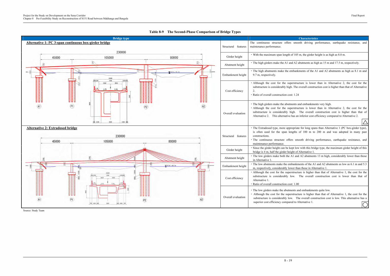
Project for the Study on Development on the Sena Corridor Final Report
Chapter 8 Pre-Feasibility Study on Reconstruction of S151 Road between Makhanga and Bangula
8 - 19
Table 8-9 The Second-Phase Comparison of Bridge Types
Bridge type Characteristics
Alternative 1: PC 3-span continuous box-girder bridge Structural features
The continuous structure offers smooth driving performance, earthquake resistance, and
maintenance performance.
Girder height ・With the maximum span length of 105 m, the girder height is as high as 8.0 m.
Abutment height ・The high girders make the A1 and A2 abutments as high as 15 m and 17.5 m, respectively.
Embankment height
・The high abutments make the embankments of the A1 and A2 abutments as high as 8.1 m and
9.7 m, respectively.
Cost efficiency
・Although the cost for the superstructure is lower than in Alternative 2, the cost for the
substructure is considerably high. The overall construction cost is higher than that of Alternative
2.
・Ratio of overall construction cost: 1.24
Overall evaluation
・The high girders make the abutments and embankments very high.
・Although the cost for the superstructure is lower than in Alternative 2, the cost for the
substructure is considerably high. The overall construction cost is higher than that of
Alternative 2. This alternative has an inferior cost efficiency compared to Alternative 2.
Alternative 2: Extradosed bridge
Structural features
・The Extradosed type, more appropriate for long spans than Alternative 1 (PC box-girder type),
is often used for the span lengths of 100 m to 200 m and was adopted in many past
constructions.
・The continuous structure offers smooth driving performance, earthquake resistance, and
maintenance performance.
Girder height ・Since the girder height can be kept low with this bridge type, the maximum girder height of this
bridge is 4 m, half the girder height of Alternative 1.
Abutment height ・The low girders make both the A1 and A2 abutments 13 m high, considerably lower than those
in Alternative 1.
Embankment height・The low abutments make the embankments of the A1 and A2 abutments as low as 6.1 m and 5.3
m, respectively, considerably lower than those in Alternative 1.
Cost efficiency
・Although the cost for the superstructure is higher than that of Alternative 1, the cost for the
substructure is considerably low. The overall construction cost is lower than that of
Alternative 1.
・Ratio of overall construction cost: 1.00
Overall evaluation
・The low girders make the abutments and embankments quite low.
・ Although the cost for the superstructure is higher than that of Alternative 1, the cost for the
substructure is considerably low. The overall construction cost is low. This alternative has a
superior cost efficiency compared to Alternative 1.
Source: Study Team
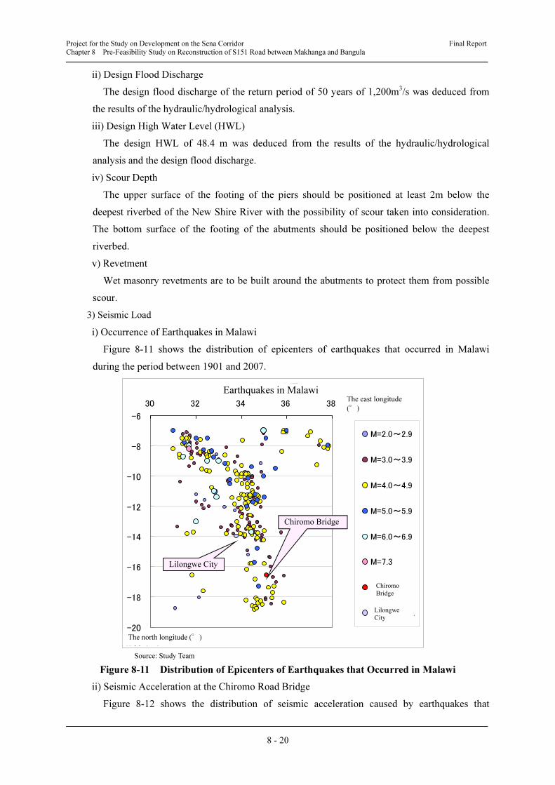
Project for the Study on Development on the Sena Corridor Final Report
Chapter 8 Pre-Feasibility Study on Reconstruction of S151 Road between Makhanga and Bangula
8 - 20
ii) Design Flood Discharge
The design flood discharge of the return period of 50 years of 1,200m3/s was deduced from
the results of the hydraulic/hydrological analysis.
iii) Design High Water Level (HWL)
The design HWL of 48.4 m was deduced from the results of the hydraulic/hydrological
analysis and the design flood discharge.
iv) Scour Depth
The upper surface of the footing of the piers should be positioned at least 2m below the
deepest riverbed of the New Shire River with the possibility of scour taken into consideration.
The bottom surface of the footing of the abutments should be positioned below the deepest
riverbed.
v) Revetment
Wet masonry revetments are to be built around the abutments to protect them from possible
scour.
3) Seismic Load
i) Occurrence of Earthquakes in Malawi
Figure 8-11 shows the distribution of epicenters of earthquakes that occurred in Malawi
during the period between 1901 and 2007.
Source: Study Team
Figure 8-11 Distribution of Epicenters of Earthquakes that Occurred in Malawi
ii) Seismic Acceleration at the Chiromo Road Bridge
Figure 8-12 shows the distribution of seismic acceleration caused by earthquakes that
マラウイの地震
-20
-18
-16
-14
-12
-10
-8
-6
30 32 34 36 38 東経 (°)
北緯 (°)
M=2.0~2.9
M=3.0~3.9
M=4.0~4.9
M=5.0~5.9
M=6.0~6.9
M=7.3
チロモ橋
リロングウェ
Chiromo Bridge
Lilongwe City
Earthquakes in Malawi The east longitude
(°)
The north longitude (°)
Chiromo
Bridge
Lilongwe
City
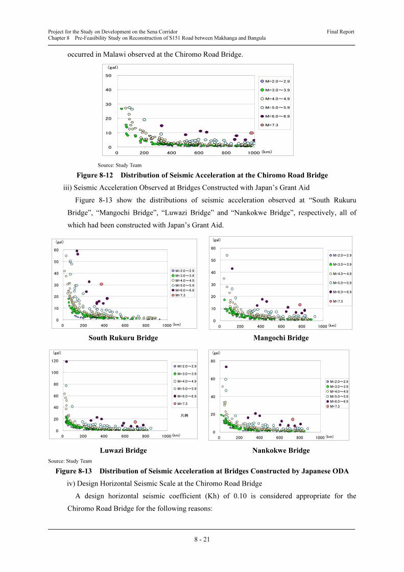
Project for the Study on Development on the Sena Corridor Final Report
Chapter 8 Pre-Feasibility Study on Reconstruction of S151 Road between Makhanga and Bangula
8 - 21
occurred in Malawi observed at the Chiromo Road Bridge.
Source: Study Team
Figure 8-12 Distribution of Seismic Acceleration at the Chiromo Road Bridge
iii) Seismic Acceleration Observed at Bridges Constructed with Japan’s Grant Aid
Figure 8-13 show the distributions of seismic acceleration observed at “South Rukuru
Bridge”, “Mangochi Bridge”, “Luwazi Bridge” and “Nankokwe Bridge”, respectively, all of
which had been constructed with Japan’s Grant Aid.
South Rukuru Bridge Mangochi Bridge
Luwazi Bridge Nankokwe Bridge
Source: Study Team
Figure 8-13 Distribution of Seismic Acceleration at Bridges Constructed by Japanese ODA
iv) Design Horizontal Seismic Scale at the Chiromo Road Bridge
A design horizontal seismic coefficient (Kh) of 0.10 is considered appropriate for the
Chiromo Road Bridge for the following reasons:
加速度 (南ルクル橋)
0
10
20
30
40
50
60
0 200 400 600 800 1000 (km)
(gal)
M=2.0~2.9
M=3.0~3.9
M=4.0~4.9
M=5.0~5.9
M=6.0~6.9
M=7.3
加速度 (マンゴチ橋)
0
10
20
30
40
50
60
0 200 400 600 800 1000 (km)
(gal)
M=2.0~2.9
M=3.0~3.9
M=4.0~4.9
M=5.0~5.9
M=6.0~6.9
M=7.3
加速度 (ルワジ橋)
0
20
40
60
80
100
120
0 200 400 600 800 1000 (km)
(gal)
M=2.0~2.9
M=3.0~3.9
M=4.0~4.9
M=5.0~5.9
M=6.0~6.9
M=7.3
凡例
加速度 (ナンコクエ橋)
0
20
40
60
80
0 200 400 600 800 1000 (km)
(gal)
M=2.0~2.9
M=3.0~3.9
M=4.0~4.9
M=5.0~5.9
M=6.0~6.9
M=7.3
加速度 (チロモ橋)
0
10
20
30
40
50
0 200 400 600 800 1000 (km)
(gal)
M=2.0~2.9
M=3.0~3.9
M=4.0~4.9
M=5.0~5.9
M=6.0~6.9
M=7.3

Project for the Study on Development on the Sena Corridor Final Report
Chapter 8 Pre-Feasibility Study on Reconstruction of S151 Road between Makhanga and Bangula
8 - 22
1. No large earthquake has occurred around the planned bridge construction position. (see
Figure 8-11)
2. No seismic acceleration larger than 30 gal has been observed around the planned bridge
construction position. (see Figure 8-12)
3. Kh of 0.10 was applied to the bridges in Malawi which were designed and constructed in
Grant Aid Cooperation Projects of Japan, including South Rukuru, Bakili Mluzi, Luwazi
and Nankokwe Bridges. (see Figures 8-13).
4. The largest seismic acceleration observed around the planned bridge construction position,
30 gal (as mentioned in the above (2)), is converted to a design horizontal seismic scale of
Kh = 0.03. However, a figure of 0.1 is the minimum Kh stipulated in the Earthquake
Resistant Design Code of Japan.
2) Strengths of Materials
The strengths of various materials to be used in this preliminary design are as follows:
i) Design standard strength of concrete for PC superstructure works
The design standard strength of concrete to be used for PC superstructure works shall be σck
=35N/mm2.
ii) Design standard strength of reinforced concrete
The design standard strength of reinforced concrete to be used for substructure works,
foundation works and reinforcement concrete members, such as curbs and parapet walls, shall
be σck=24N/mm2.
iii) Design standard strength of plain concrete
The design standard strength of concrete to be used for plain concrete members, such as
levelling concrete and caulking concrete for footways, shall be σck=18N/mm2.
iv) Reinforcing bars
Reinforcing bars to be used in this project shall satisfy the SD345 specifications.
v) PC steel
The specifications of PC steel to be used on the planned bridge shall be as follows:
Longitudinal: SWPR7BL 12S15.2B
Diagonal: 19S15.2B, 12S15.2B
c) Outline of the Bridge Design
A summary of the design of the planned bridge is given in Table 8-10. Figure 8-14 and
Figure 8-15 show the outline design drawings prepared in accordance with the procedures of the
preliminary design mentioned above.

Project for the Study on Development on the Sena Corridor Final Report
Chapter 8 Pre-Feasibility Study on Reconstruction of S151 Road between Makhanga and Bangula
8 - 23
Table 8-10 Outline of the Bridge Design
Item Type / Specifications
Bridge construction position A position where a bridge crosses over two islands and is connected to
the existing road on both sides.
Width
Bridge
Width of carriageway: 3.35 m × 2 = 6.7 m,
Bicycle roads: 0.3 m × 2 = 0.6 m,
Width of footways: 1.2 m × 2 = 2.4 m,
Total: 9.7 m (Effective road width),
Curbs: 0.4 m × 2 = 0.8 m and Total: 10.5 m (Total road width)
Access roads
Width of carriageway: 3.35 m × 2 = 6.7 m,
Bicycle roads: 0.3 m × 2 = 0.6 m,
Width of footways: 1.2 m × 2 = 2.4 m,
Total: 9.7 m (Effective road width)
Protective shoulders: 1.0 m × 2 = 2.0 m and
Total: 11.7 m (Total road width)
Bridge type Three-span Extradosed bridge
Bridge length, span lengths 45.0 m + 105.0 m + 80.0 m = 230.0 m
Bridge surface Asphalt pavement (70 mm on the carriageway)
Abutment A1
(Bangula side)
Type Inverted T-type Abutment
Height of structure 13.0 m
Cast-in-situ concrete pile Diameter = 1.5 m, Length = 25.5 m, Number of piles = 6
Abutment A2
(Makhanga
side)
Type Inverted T-type Abutment
Height of structure 13.0 m
Cast-in-situ concrete pile Diameter = 1.5 m, Length = 23.5 m, Number of piles = 6
Pier P1
Type Oval pier
Height of structure 15.5 m
Cast-in-situ concrete pile Diameter = 1.5 m, Length = 21.5 m, Number of piles = 6
Pier P2
Type Oval pier
Height of structure 21.0 m
Cast-in-situ concrete pile Diameter = 1.5 m, Length = 17.5 m, Number of piles = 16
Access roads Length Bangula side: ca. 150 m, Makhanga side: ca. 100 m
Surface Asphalt pavement (surface course: 50 mm)
Revetments Abutment A1 Wet masonry work
Abutment A2 Wet masonry work
Source: Study Team
8.2.3 Preliminary Design of New Shire Bridge
(1) Workflow of the Preliminary Design
In the preliminary design, studies required for the construction of a road bridge downstream
of the existing Kamuzu Truss Bridge, including a field survey and studies for the selection of a
bridge construction position, road alignment, scale of the bridge and bridge type, will be
implemented. The results of these studies will be used to select the best bridge type. Then, the
project cost will be estimated. Figure 8-16 shows the workflow of the preliminary design.

Project for the Study on Development on the Sena Corridor Final Report
Chapter 8 Pre-Feasibility Study on Reconstruction of S151 Road between Makhanga and Bangula
8 - 24
Source: Study Team
Figure 8-14 General Drawing of Chiromo Road Bridge

Project for the Study on Development on the Sena Corridor
Final Report
Chapter 8 Pre-Feasibility Study on Reconstruction of S151 Road between Makhanga and Bangula
8 - 25
S
ourc
e: S
tudy T
eam
Fig
ure
8-1
5
Pla
n o
f th
e A
cces
s R
oa
ds
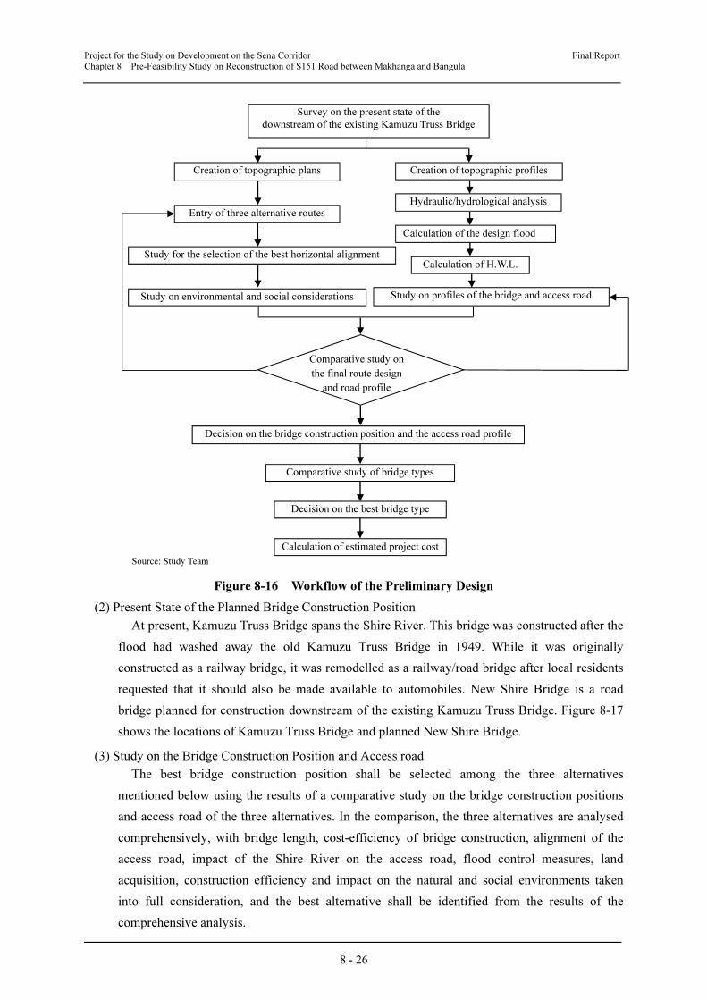
Project for the Study on Development on the Sena Corridor Final Report
Chapter 8 Pre-Feasibility Study on Reconstruction of S151 Road between Makhanga and Bangula
8 - 26
Source: Study Team
Figure 8-16 Workflow of the Preliminary Design
(2) Present State of the Planned Bridge Construction Position
At present, Kamuzu Truss Bridge spans the Shire River. This bridge was constructed after the
flood had washed away the old Kamuzu Truss Bridge in 1949. While it was originally
constructed as a railway bridge, it was remodelled as a railway/road bridge after local residents
requested that it should also be made available to automobiles. New Shire Bridge is a road
bridge planned for construction downstream of the existing Kamuzu Truss Bridge. Figure 8-17
shows the locations of Kamuzu Truss Bridge and planned New Shire Bridge.
(3) Study on the Bridge Construction Position and Access road
The best bridge construction position shall be selected among the three alternatives
mentioned below using the results of a comparative study on the bridge construction positions
and access road of the three alternatives. In the comparison, the three alternatives are analysed
comprehensively, with bridge length, cost-efficiency of bridge construction, alignment of the
access road, impact of the Shire River on the access road, flood control measures, land
acquisition, construction efficiency and impact on the natural and social environments taken
into full consideration, and the best alternative shall be identified from the results of the
comprehensive analysis.
Survey on the present state of the
downstream of the existing Kamuzu Truss Bridge
Creation of topographic plans Creation of topographic profiles
Entry of three alternative routes
Study for the selection of the best horizontal alignment
Study on environmental and social considerations
Calculation of the design flood
Calculation of H.W.L.
Study on profiles of the bridge and access road
Comparative study on
the final route design
and road profile
Decision on the bridge construction position and the access road profile
Comparative study of bridge types
Decision on the best bridge type
Hydraulic/hydrological analysis
Calculation of estimated project cost
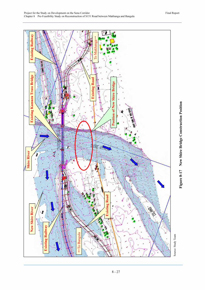
Project for the Study on Development on the Sena Corridor
Final Report
Chapter 8 Pre-Feasibility Study on Reconstruction of S151 Road between Makhanga and Bangula
8 - 27
So
urc
e: S
tud
y T
eam
Fig
ure
8-1
7
New
Sh
ire
Bri
dg
e C
on
stru
ctio
n P
osi
tio
n
Ex
isti
ng K
am
uzu
Tru
ss B
rid
ge
Sh
ire R
iver
Po
siti
on
of
New
Sh
ire B
rid
ge
Ex
isti
ng R
ail
wa
y
Ex
isti
ng R
oad
New
Sh
ire R
iver
Ex
isti
ng R
ail
wa
y
Ex
isti
ng R
oad
To
Mak
han
ga→
←T
o B
ang
ula
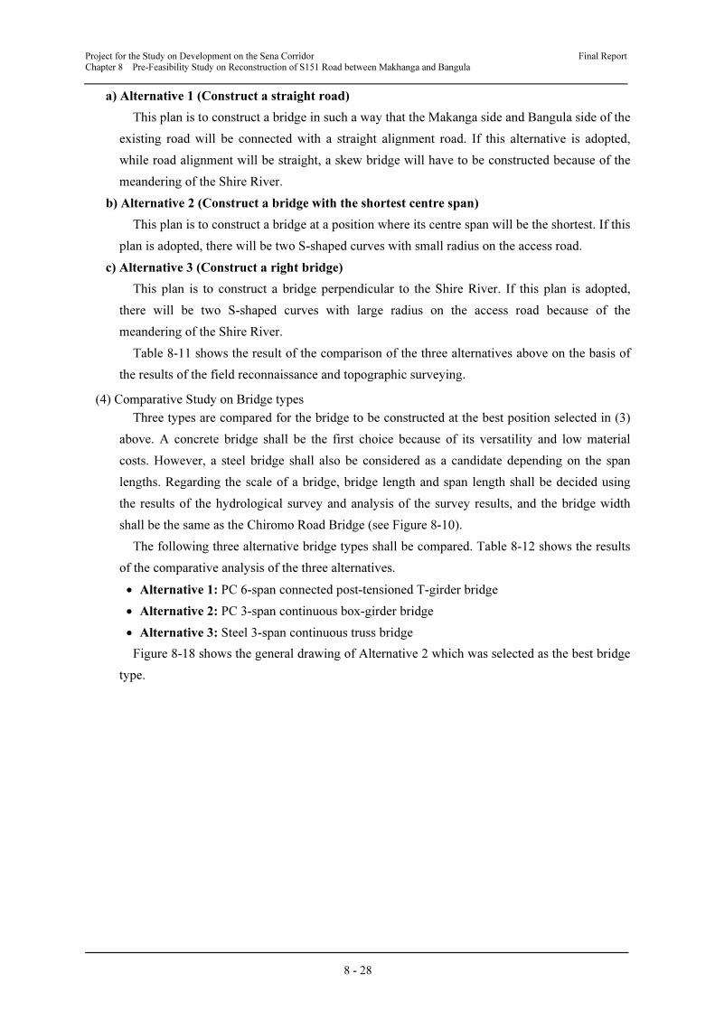
Project for the Study on Development on the Sena Corridor Final Report
Chapter 8 Pre-Feasibility Study on Reconstruction of S151 Road between Makhanga and Bangula
8 - 28
a) Alternative 1 (Construct a straight road)
This plan is to construct a bridge in such a way that the Makanga side and Bangula side of the
existing road will be connected with a straight alignment road. If this alternative is adopted,
while road alignment will be straight, a skew bridge will have to be constructed because of the
meandering of the Shire River.
b) Alternative 2 (Construct a bridge with the shortest centre span)
This plan is to construct a bridge at a position where its centre span will be the shortest. If this
plan is adopted, there will be two S-shaped curves with small radius on the access road.
c) Alternative 3 (Construct a right bridge)
This plan is to construct a bridge perpendicular to the Shire River. If this plan is adopted,
there will be two S-shaped curves with large radius on the access road because of the
meandering of the Shire River.
Table 8-11 shows the result of the comparison of the three alternatives above on the basis of
the results of the field reconnaissance and topographic surveying.
(4) Comparative Study on Bridge types
Three types are compared for the bridge to be constructed at the best position selected in (3)
above. A concrete bridge shall be the first choice because of its versatility and low material
costs. However, a steel bridge shall also be considered as a candidate depending on the span
lengths. Regarding the scale of a bridge, bridge length and span length shall be decided using
the results of the hydrological survey and analysis of the survey results, and the bridge width
shall be the same as the Chiromo Road Bridge (see Figure 8-10).
The following three alternative bridge types shall be compared. Table 8-12 shows the results
of the comparative analysis of the three alternatives.
• Alternative 1: PC 6-span connected post-tensioned T-girder bridge
• Alternative 2: PC 3-span continuous box-girder bridge
• Alternative 3: Steel 3-span continuous truss bridge
Figure 8-18 shows the general drawing of Alternative 2 which was selected as the best bridge
type.
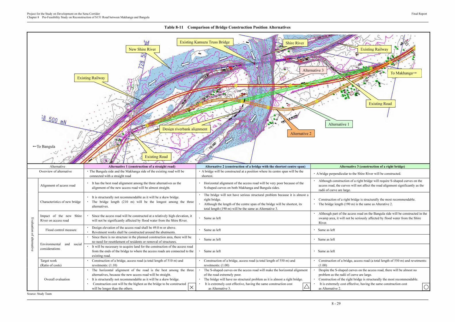
Project for the Study on Development on the Sena Corridor Final Report
Chapter 8 Pre-Feasibility Study on Reconstruction of S151 Road between Makhanga and Bangula
8 - 29
Table 8-11 Comparison of Bridge Construction Position Alternatives
Alternative Alternative 1 (construction of a straight road) Alternative 2 (construction of a bridge with the shortest centre span) Alternative 3 (construction of a right bridge)
Overview of alternative ・ The Bangula side and the Makhanga side of the existing road will be
connected with a straight road
・ A bridge will be constructed at a position where its centre span will be the
shortest. ・ A bridge perpendicular to the Shire River will be constructed.
Evalu
atio
n o
f alte
rnativ
e
Alignment of access road ・ It has the best road alignment among the three alternatives as the
alignment of the new access road will be almost straight.
・ Horizontal alignment of the access road will be very poor because of the
S-shaped curves on both Makhanga and Bangula sides.
・ Although construction of a right bridge will require S-shaped curves on the
access road, the curves will not affect the road alignment significantly as the
radii of curve are large.
Characteristics of new bridge
・ It is structurally not recommendable as it will be a skew bridge.
・ The bridge length (210 m) will be the longest among the three
alternatives.
・ The bridge will not have serious structural problem because it is almost a
right bridge.
・ Although the length of the centre span of the bridge will be shortest, its
total length (190 m) will be the same as Alternative 3.
・ Construction of a right bridge is structurally the most recommendable.
・ The bridge length (190 m) is the same as Alterative 2.
Impact of the new Shire
River on access road
・ Since the access road will be constructed at a relatively high elevation, it
will not be significantly affected by flood water from the Shire River. ・ Same as left
・ Although part of the access road on the Bangula side will be constructed in the
swamp area, it will not be seriously affected by flood water from the Shire
River.
Flood control measure ・ Design elevation of the access road shall be 49.0 m or above.
・ Revetment works shall be constructed around the abutments. ・ Same as left ・ Same as left
Environmental and social
considerations
・ Since there is no structure in the planned construction area, there will be
no need for resettlement of residents or removal of structures. ・ Same as left ・ Same as left
・ It will be necessary to acquire land for the construction of the access road
from the ends of the bridge to where the access roads are connected to the
existing road.
・ Same as left ・ Same as left
Target work
(Ratio of costs)
・ Construction of a bridge, access road (a total length of 510 m) and
revetments: (1.10)
・ Construction of a bridge, access road (a total length of 550 m) and
revetments: (1.00)
・ Construction of a bridge, access road (a total length of 550 m) and revetments:
(1.00)
Overall evaluation
・ The horizontal alignment of the road is the best among the three
alternatives, because the new access road will be straight.
・ It is structurally not recommendable as it will be a skew bridge.
・ Construction cost will be the highest as the bridge to be constructed
will be longer than the others.
・ The S-shaped curves on the access road will make the horizontal alignment
of the road extremely poor.
・ The bridge will have no structural problem as it is almost a right bridge.
・ It is extremely cost effective, having the same construction cost
as Alternative 3.
・ Despite the S-shaped curves on the access road, there will be almost no
problem as the radii of curve are large.
・ Construction of the right bridge is structurally the most recommendable.
・ It is extremely cost effective, having the same construction cost
as Alternative 2.
Source: Study Team
Existing Road
Existing Kamuzu Truss Bridge
To Makhanga→
Existing Railway
Existing Railway
←To Bangula
Existing Road
Design riverbank alignment
Shire River
New Shire River
Alternative 1
Alternative 2
Alternative 3
×
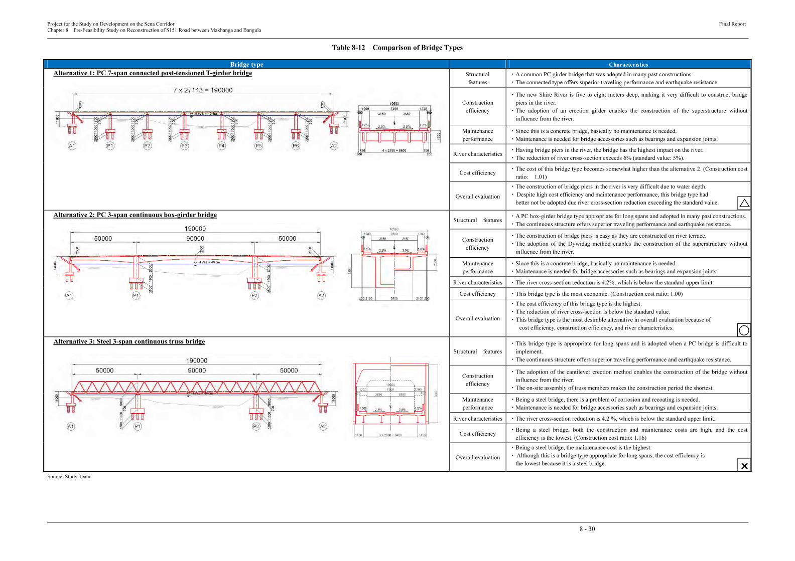
Project for the Study on Development on the Sena Corridor Final Report
Chapter 8 Pre-Feasibility Study on Reconstruction of S151 Road between Makhanga and Bangula
8 - 30
Table 8-12 Comparison of Bridge Types
Bridge type Characteristics
Alternative 1: PC 7-span connected post-tensioned T-girder bridge
Structural
features
・A common PC girder bridge that was adopted in many past constructions.
・The connected type offers superior traveling performance and earthquake resistance.
Construction
efficiency
・The new Shire River is five to eight meters deep, making it very difficult to construct bridge
piers in the river.
・The adoption of an erection girder enables the construction of the superstructure without
influence from the river.
Maintenance
performance
・Since this is a concrete bridge, basically no maintenance is needed.
・Maintenance is needed for bridge accessories such as bearings and expansion joints.
River characteristics・Having bridge piers in the river, the bridge has the highest impact on the river.
・The reduction of river cross-section exceeds 6% (standard value: 5%).
Cost efficiency ・The cost of this bridge type becomes somewhat higher than the alternative 2. (Construction cost
ratio: 1.01)
Overall evaluation
・The construction of bridge piers in the river is very difficult due to water depth.
・ Despite high cost efficiency and maintenance performance, this bridge type had
better not be adopted due river cross-section reduction exceeding the standard value.
Alternative 2: PC 3-span continuous box-girder bridge
Structural features・A PC box-girder bridge type appropriate for long spans and adopted in many past constructions.
・The continuous structure offers superior traveling performance and earthquake resistance.
Construction
efficiency
・The construction of bridge piers is easy as they are constructed on river terrace.
・The adoption of the Dywidag method enables the construction of the superstructure without
influence from the river.
Maintenance
performance
・Since this is a concrete bridge, basically no maintenance is needed.
・Maintenance is needed for bridge accessories such as bearings and expansion joints.
River characteristics ・The river cross-section reduction is 4.2%, which is below the standard upper limit.
Cost efficiency ・This bridge type is the most economic. (Construction cost ratio: 1.00)
Overall evaluation
・ The cost efficiency of this bridge type is the highest.
・ The reduction of river cross-section is below the standard value.
・ This bridge type is the most desirable alternative in overall evaluation because of
cost efficiency, construction efficiency, and river characteristics.
Alternative 3: Steel 3-span continuous truss bridge
Structural features
・This bridge type is appropriate for long spans and is adopted when a PC bridge is difficult to
implement.
・The continuous structure offers superior traveling performance and earthquake resistance.
Construction
efficiency
・The adoption of the cantilever erection method enables the construction of the bridge without
influence from the river.
・The on-site assembly of truss members makes the construction period the shortest.
Maintenance
performance
・Being a steel bridge, there is a problem of corrosion and recoating is needed.
・Maintenance is needed for bridge accessories such as bearings and expansion joints.
River characteristics ・The river cross-section reduction is 4.2 %, which is below the standard upper limit.
Cost efficiency ・Being a steel bridge, both the construction and maintenance costs are high, and the cost
efficiency is the lowest. (Construction cost ratio: 1.16)
Overall evaluation
・Being a steel bridge, the maintenance cost is the highest.
・ Although this is a bridge type appropriate for long spans, the cost efficiency is
the lowest because it is a steel bridge.
Source: Study Team
×

Project for the Study on Development on the Sena Corridor Final Report
Chapter 8 Pre-Feasibility Study on Reconstruction of S151 Road between Makhanga and Bangula
8 - 31
Source: Study Team
Figure 8-18 General Drawing of New Shire Bridge
Project for the Study on Development on the Sena Corridor Final Report
Chapter 8 Pre-Feasibility Study on Reconstruction of S151 Road between Makhanga and Bangula
8 - 32
8.3 Preliminary Cost Estimation
8.3.1 Basic Policy for Construction of Road and Bridges
This plan is prepared as mentioned below based on the actual conditions.
• The bridges and road will be constructed within the road ROW. In order to construct the
new bridges and roads, the Malawi government shall procure the necessary land.
• The construction method shall be applied to avoid the influence of flood in the rainy season.
• The construction of foundation and substructure for bridges shall be done in the dry season
in principle.
• Access to the site shall be from the Bangula side. (The completion time of the road
construction for S151 is not confirmed yet.) Therefore a temporary bridge shall be built for
use during the construction period in order to supply the equipment, material and
manpower.
• The procurement period for the material is not steady in Malawi, therefore a leeway for the
start of certain work will be necessary.
• The fill material shall be obtained as close as possible to the site from a quarry.
8.3.2 Construction Plan and Procurement Conditions
(1) Preliminary Conditions for Construction Plan
Each work method is mentioned below.
a) Construction of Bridge
1) Concrete Bridge
The planned bridges of Chiromo Road Bridge and New Shire Bridge are PC concrete box
girders. In Malawi it is impossible to procure the necessary equipment and material for the
mentioned bridges, so those shall be imported from abroad. Also the structural foundation such
as a pile or open caisson could be considered and the procurement conditions would be same as
for the superstructure of the bridge. For the RC bridge, only the reinforcement bars need to be
imported.
2) Truss Bridge
Steel trusses and the launching equipment shall be Fabricated and procured from abroad.
b) Concrete Work
The onsite temperature is high year-round. The maximum daytime temperature only drops
below 30°C for two months. A small quantity of concrete could be cast early in the morning or
at night. However in order to cast the huge concrete volume such as the footing of the
substructure, concrete casting would need to continue during day and night, therefore the
concrete temperature would need to be controlled by a cooling plant or ice maker plant.
c) Culvert Work
The Malawi concrete box type uses concrete pipe which is not a hume pipe, and corrugated
metal pipes as a culvert structure. To prevent the corrosion of corrugated metal pipes, a
Project for the Study on Development on the Sena Corridor Final Report
Chapter 8 Pre-Feasibility Study on Reconstruction of S151 Road between Makhanga and Bangula
8 - 33
bituminous coating is applied to the external surface during road construction between
Chikwawa and Bangula. The Contractors do not recommend the use of corrugated metal pipes
because of theft or vandalism which could cause the culvert to collapse. Therefore the use of a
concrete culvert has been recommended.
d) Embankment Work
The selected material for fill shall be obtained as close as possible to the site and the work
shall be carried out as much as possible in the dry season.
e) Pavement Work
The aggregate used for base course and chip seal surfacing for the pavement could be
procured in the existing quarry in Blantyre. The major contractors have sufficient construction
equipment for paving work. However the bitumen shall be imported from abroad.
f) Temporary Yard
A temporary yard shall be established close to the bridge site on the Bangula side. In this case
the land might off the main route, so approval must be obtained from the GoM in order to use it.
The purpose of the temporary yard is;
• Site office
• Plant (Concrete)
• Accommodation for workers
• Park for equipment
• Deposit for material
• Work shop for reinforcement bar
• Work shop for form work
(2) Procurement Condition
a) Aggregate
The coarse aggregate used for concrete could be procured in the existing quarry in Blantyre.
On the other hand the fine aggregate could be procured near the site. Currently one quarry is
being used for the improvement of S515 road between Bangula and Chikwawa. According to
the contractor, the amount of useful material might be limited.
b) Cement
The import volume of clinker is extremely decreased and production of cement in Malawi is
being suspended. Procurement from Zambia or RSA is presently insufficient, so some
contractors are trying to import from another country.
c) Reinforcement Bar and Steel Material
The amount of steel produced in RSA decreased in 2008 and there is a problem of supply
shortage, but it is expected that production by major steel companies will resume in early 2012.
However, procurement shall be confirmed before the construction begins from RSA or
Mozambique as well as from a third country.
d) Bitumen
Just as for reinforcement bars, the procurement is not easy. Sometimes the procurement takes
Project for the Study on Development on the Sena Corridor Final Report
Chapter 8 Pre-Feasibility Study on Reconstruction of S151 Road between Makhanga and Bangula
8 - 34
several month. The procurement shall be confirmed before the construction begins from RSA as
well as a third country.
e) Material and equipment for Bridge
It is very difficult to procure the material and equipment for bridge construction. The
procurement shall be confirmed before the construction begins from RSA as well as a third
country.
f) Construction Equipment
Major contractors in Malawi have sufficient equipment for the road construction. However
they do not have special equipment for bridge construction. Hence, special equipment shall be
procured from abroad.
g) Labour
Some skilled labour could be procured in Lilongwe or Blantyre. Common labour could be
procured near the site. However specialists for construction of the foundation or superstructure
of the bridge shall be from abroad.
h) Contractor in Malawi
There are more than 10 A-class contractors and they have equipment for road construction
mainly and 25ton truck cranes, asphalt plant and concrete plant.
8.3.3 Supervision of Construction by a Consultant
(1) Supervision of Quality Control and Finished Dimension
The quality and finished dimension of each structure shall be kept based on the contract
document. The works for the project are PC bridge, RC bridge, steel truss bridges, drainage,
earthworks, pavement and miscellaneous structures. For the construction experienced engineers
will be needed from other countries.
(2) Supervision of Progress of Works
Prior to starting the project the construction method, equipment, number of labourers shall be
studied appropriately and then an adequate program shall be made to avoid any shortage and
delay. In case of delay during the construction period, the consultant will order the contractor to
modify the plan and the program immediately in order to recover the delay.
(3) Supervision of safety
Accidents on the construction site cause lots of problems and difficulty for the project. So the
consultant and contractors shall take necessary measures to avoid any accidents. The contractor
shall educate all the labourers in appropriate health and safety procedures.
In case of an emergency, a special organization shall be established prior to the
commencement of the work and take the necessary action immediately if accident happens.
On the other hand, to protect the labourers, equipment and construction work from heavy rain
and flood, the contractors shall have good knowledge of the weather information and/or
forecasting and establish a safety system.
To avoid the traffic accidents and any trouble with third parties, a safety measure plan shall
be considered. The plan shall include safety matter of the intersections with public roads, night

Project for the Study on Development on the Sena Corridor Final Report
Chapter 8 Pre-Feasibility Study on Reconstruction of S151 Road between Makhanga and Bangula
8 - 35
time, over-loading of transport material, the material logistics and distribution of guards.
(4) Environmental Protection Measures
Mitigation measures against vibration, noise and water contamination shall be considered and
controlled by the Consultant and Contractors which shall maintain coordination with local
residents.
8.3.4 Estimation of Project Cost
The estimation of construction cost is calculated based on the condition mentioned below.
The project cost includes 10% contingency and engineering fee, and does not include tax in
Malawi.
• Bridge:Based on the consideration of construction site and structures for Chiromo Road
Bridge, New Shire Bridge, those costs are calculated with comparison to similar
construction projects abroad. An Extradosed bridge is applied for the Chiromo Road Bridge,
and cost is higher than an ordinarily continuous concrete box girder type.
• Road:The completed road construction between Nsanje and Bangula which was signed in
2008 is similar to this subjected project. So those data is referred to in this study. The
escalation of construction cost is confirmed at about 16% per annum based on the certificate
for payment in the road construction project due to escalated costs for fuel and others
construction material. This information is considered in the calculation of construction
costs.
• Others:The present situation to accomplish the project due to the shortage of fuel, cement,
steel material and asphalt is clearly difficult due to the delay of two Japanese grand aid
projects which are still on going. If such difficult conditions could not be solved, the project
cannot be completed within the budget and in this situation the start of the project could be
put into jeopardy.
Table 8-13 summarises the estimated project cost for the reconstruction of S151 road
between Makhanga and Bangula.
Table 8-13 Estimated Project Cost
Cost Item Estimated Project Cost (US$ million)
Improvement of Road between Makhanga and
Bangula 14.52
Chiromo Road Bridge Superstructure works 15.64
22.08 Substructure works 6.44
New Shire Bridge Superstructure works 12.80
19.48 Substructure works 6.68
Total Project Cost 56.08
Source: Study Team
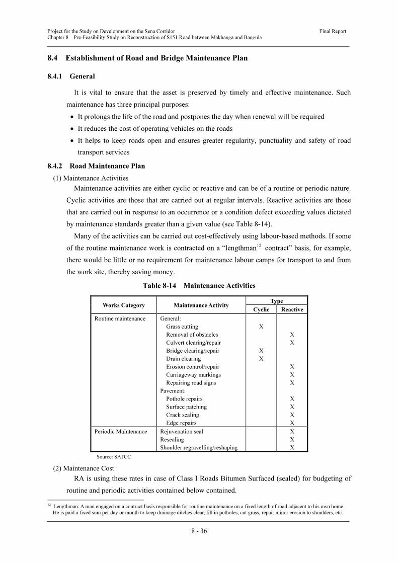
Project for the Study on Development on the Sena Corridor Final Report
Chapter 8 Pre-Feasibility Study on Reconstruction of S151 Road between Makhanga and Bangula
8 - 36
8.4 Establishment of Road and Bridge Maintenance Plan
8.4.1 General
It is vital to ensure that the asset is preserved by timely and effective maintenance. Such
maintenance has three principal purposes:
• It prolongs the life of the road and postpones the day when renewal will be required
• It reduces the cost of operating vehicles on the roads
• It helps to keep roads open and ensures greater regularity, punctuality and safety of road
transport services
8.4.2 Road Maintenance Plan
(1) Maintenance Activities
Maintenance activities are either cyclic or reactive and can be of a routine or periodic nature.
Cyclic activities are those that are carried out at regular intervals. Reactive activities are those
that are carried out in response to an occurrence or a condition defect exceeding values dictated
by maintenance standards greater than a given value (see Table 8-14).
Many of the activities can be carried out cost-effectively using labour-based methods. If some
of the routine maintenance work is contracted on a “lengthman12 contract” basis, for example,
there would be little or no requirement for maintenance labour camps for transport to and from
the work site, thereby saving money.
Table 8-14 Maintenance Activities
Works Category Maintenance Activity Type
Cyclic Reactive
Routine maintenance General:
Grass cutting
Removal of obstacles
Culvert clearing/repair
Bridge clearing/repair
Drain clearing
Erosion control/repair
Carriageway markings
Repairing road signs
Pavement:
Pothole repairs
Surface patching
Crack sealing
Edge repairs
X
X
X
X
X
X
X
X
X
X
X
X
Periodic Maintenance Rejuvenation seal
Resealing
Shoulder regravelling/reshaping
X
X
X
Source: SATCC
(2) Maintenance Cost
RA is using these rates in case of Class I Roads Bitumen Surfaced (sealed) for budgeting of
routine and periodic activities contained below contained.
12 Lengthman: A man engaged on a contract basis responsible for routine maintenance on a fixed length of road adjacent to his own home.
He is paid a fixed sum per day or month to keep drainage ditches clear, fill in potholes, cut grass, repair minor erosion to shoulders, etc.

Project for the Study on Development on the Sena Corridor Final Report
Chapter 8 Pre-Feasibility Study on Reconstruction of S151 Road between Makhanga and Bangula
8 - 37
Good: US$980 per km/year including grass cutting, ditch and culvert
cleaning, patch potholes and others
Fair: US$1,445 per km/year including grass cutting, ditch and culvert
cleaning, pothole patching, grade shoulders and others
Poor: US$2,330 per km/year including grass cutting, ditch and culvert
cleaning, grade shoulders, 2 times patch potholes and others
(3) Consideration of Life Cycle
Even with strict adherence to proper standards of construction, roads deteriorate with the
passage of time. The rate of deterioration may vary greatly depending on the climate, the
strength of the pavement and underlying subgrade, the traffic volume and axle loads. The wear
and tear of road surfaces by traffic is aggravated by rainwater and by changes in temperature.
Cracking occurs in the bituminous surfacing which, together with the ingress of rainwater, often
leads to pavement failures.
When a double surface dressing (DBST) for design road are adopted, it is proposed to
conduct slurry seal work as major maintenance at after 10 years form start of service. (see
Figure 8-19)
Source: Study Team
Figure 8-19 Deterioration of Road Condition by Timing
8.4.3 Bridge Maintenance Plan
The GoM will be in charge of the implementation and management of this project. The
management of bridges is the responsibility of regional offices of RA, and the Southern
Regional Office of RA takes charge of this project. While maintenance works was previously
performed by the provincial office of MoTPI, these are now outsourced by RA to private firms
selected by bidding. The maintenance works after the completion of this project is generally
divided into those performed regularly every year and those performed at intervals of several
years. The following works are needed for this project.
Date of Construction
Co
nd
itio
n
Age (Year)
Level of maintenance required to
control deterioration and extend
life
Standard of maintenance
for resurfacing Major maintenanceRemaining
service life
Remaining actual life
Minimum tolerable
condition
Condition at which
pavements are
actually replaced
Uncontrolled
Controlled
Project for the Study on Development on the Sena Corridor Final Report
Chapter 8 Pre-Feasibility Study on Reconstruction of S151 Road between Makhanga and Bangula
8 - 38
(1) Inspection and Maintenance Needed Every Year
• Removal of sand and dirt accumulating in bridge deck drain pipes, the areas around
bearings, gutters and other drain facilities, and cleaning of these areas.
• Maintenance of traffic safety facilities including re-application of surface signs.
• Inspection and repair of bank protection and riverbed protection works after floods.
• Removal of boulders, driftwood, etc. after floods.
(2) Maintenance Performed at Intervals of Several Years
• Patching or overlaying of bridge deck pavement; at intervals of about 5 years.
• Replacement of expansion joints; at intervals of about 10 years.
Because bank protection and riverbed protection works are important for bridge maintenance
in this project, these structures are designed based on the design flood flow probability of one
flood every 50 years. However, these structures are subject to the risk of collapse and being
washed away as a result of unpredictable localized erosion or a flood exceeding the assumed
probability. Therefore, MoTPI and RA are requested to establish a system so that relevant
departments will be able to perform inspection promptly after a flood and MoTPI and RA will
be able to promptly repair any damage, failure, etc. in these structures. If left untreated, such
conditions may lead to backfill earth behind abutments being washed away, leading to
subsidence of the abutments and disruption of traffic in the worst case.
(3) Operation and Maintenance Cost
Maintenance and management of the new bridge to be constructed by this Project will be
undertaken by RA, which contracts private companies to maintain bridges using the budget
appropriated by the government. As shown in Table 12-15, the maintenance works required
after completion of Chiromo Road Bridge consist of daily inspection, cleaning, and repair, the
cost of which is estimated at MWK 4,064 thousand on the annual average. This is only 0.06%
of RA’s total maintenance budget of MWK 7,288,746 thousand (2010/2011), which can amply
cover the maintenance cost of the Project.
8.5 Economic Analysis of Reconstruction of S151 Road between Makhanga and
Bangula
8.5.1 Methodology of Economic Analysis using HDM-4 Model
The economic analysis of the reconstruction of S151 Road between Makhanga and Bangula
is conducted using the Highway Development and Management (HDM-4) model of an
economical evaluation model. The HDM-4 is generally applied to the evaluation of road
projects in Malawi by RA. The development of HDM-4 was sponsored by several agencies
including the World Bank and Asian Development Bank.
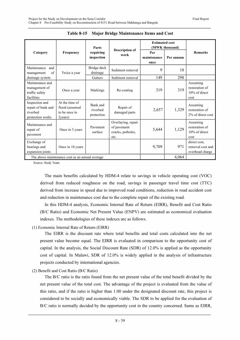
Project for the Study on Development on the Sena Corridor Final Report
Chapter 8 Pre-Feasibility Study on Reconstruction of S151 Road between Makhanga and Bangula
8 - 39
Table 8-15 Major Bridge Maintenance Items and Cost
Category Frequency
Parts
requiring
inspection
Description of
work
Estimated cost
(MWK thousand)
Remarks Per
maintenance
once
Per annum
Maintenance and
management of
drainage system
Twice a year
Bridge deck
drainage Sediment removal 9 18
Gutters Sediment removal 149 298
Maintenance and
management of
traffic safety
facilities
Once a year Markings Re-coating 319 319
Assuming
restoration of
10% of direct
cost
Inspection and
repair of bank and
riverbed
protection works
At the time of
flood (assumed
to be once in
2years)
Bank and
riverbed
protection
Repair of
damaged parts 2,657 1,329
Assuming
restoration of
2% of direct cost
Maintenance and
repair of
pavement
Once in 5 years Pavement
surface
Overlaying, repair
of pavement
cracks, potholes,
etc.
5,644 1,129
Assuming
restoration of
10% of direct
cost
Exchange of
bearings and
expansion joints
Once in 10 years 9,709 971
direct cost,
removal cost and
overhead charge
The above maintenance cost as an annual average 4,064
Source: Study Team
The main benefits calculated by HDM-4 relate to savings in vehicle operating cost (VOC)
derived from reduced roughness on the road, savings in passenger travel time cost (TTC)
derived from increase in speed due to improved road conditions, reduction in road accident cost
and reduction in maintenance cost due to the complete repair of the existing road.
In this HDM-4 analysis, Economic Internal Rate of Return (EIRR), Benefit and Cost Ratio
(B/C Ratio) and Economic Net Present Value (ENPV) are estimated as economical evaluation
indexes. The methodologies of these indexes are as follows.
(1) Economic Internal Rate of Return (EIRR)
The EIRR is the discount rate where total benefits and total costs calculated into the net
present value become equal. The EIRR is evaluated in comparison to the opportunity cost of
capital. In the analysis, the Social Discount Rate (SDR) of 12.0% is applied as the opportunity
cost of capital. In Malawi, SDR of 12.0% is widely applied in the analysis of infrastructure
projects conducted by international agencies.
(2) Benefit and Cost Ratio (B/C Ratio)
The B/C ratio is the ratio found from the net present value of the total benefit divided by the
net present value of the total cost. The advantage of the project is evaluated from the value of
this ratio, and if the ratio is higher than 1.00 under the designated discount rate, this project is
considered to be socially and economically viable. The SDR to be applied for the evaluation of
B/C ratio is normally decided by the opportunity cost in the country concerned. Same as EIRR,
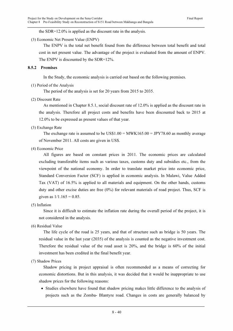
Project for the Study on Development on the Sena Corridor Final Report
Chapter 8 Pre-Feasibility Study on Reconstruction of S151 Road between Makhanga and Bangula
8 - 40
the SDR=12.0% is applied as the discount rate in the analysis.
(3) Economic Net Present Value (ENPV)
The ENPV is the total net benefit found from the difference between total benefit and total
cost in net present value. The advantage of the project is evaluated from the amount of ENPV.
The ENPV is discounted by the SDR=12%.
8.5.2 Premises
In the Study, the economic analysis is carried out based on the following premises.
(1) Period of the Analysis
The period of the analysis is set for 20 years from 2015 to 2035.
(2) Discount Rate
As mentioned in Chapter 8.5.1, social discount rate of 12.0% is applied as the discount rate in
the analysis. Therefore all project costs and benefits have been discounted back to 2015 at
12.0% to be expressed as present values of that year.
(3) Exchange Rate
The exchange rate is assumed to be US$1.00 = MWK165.00 = JPY78.60 as monthly average
of November 2011. All costs are given in US$.
(4) Economic Price
All figures are based on constant prices in 2011. The economic prices are calculated
excluding transferable items such as various taxes, customs duty and subsidies etc., from the
viewpoint of the national economy. In order to translate market price into economic price,
Standard Conversion Factor (SCF) is applied in economic analysis. In Malawi, Value Added
Tax (VAT) of 16.5% is applied to all materials and equipment. On the other hands, customs
duty and other excise duties are free (0%) for relevant materials of road project. Thus, SCF is
given as 1/1.165 = 0.85.
(5) Inflation
Since it is difficult to estimate the inflation rate during the overall period of the project, it is
not considered in the analysis.
(6) Residual Value
The life cycle of the road is 25 years, and that of structure such as bridge is 50 years. The
residual value in the last year (2035) of the analysis is counted as the negative investment cost.
Therefore the residual value of the road asset is 20%, and the bridge is 60% of the initial
investment has been credited in the final benefit year.
(7) Shadow Prices
Shadow pricing in project appraisal is often recommended as a means of correcting for
economic distortions. But in this analysis, it was decided that it would be inappropriate to use
shadow prices for the following reasons:
• Studies elsewhere have found that shadow pricing makes little difference to the analysis of
projects such as the Zomba- Blantyre road. Changes in costs are generally balanced by
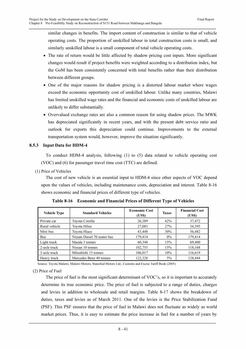
Project for the Study on Development on the Sena Corridor Final Report
Chapter 8 Pre-Feasibility Study on Reconstruction of S151 Road between Makhanga and Bangula
8 - 41
similar changes in benefits. The import content of construction is similar to that of vehicle
operating costs. The proportion of unskilled labour in total construction costs is small, and
similarly unskilled labour is a small component of total vehicle operating costs.
• The rate of return would be little affected by shadow pricing cost inputs. More significant
changes would result if project benefits were weighted according to a distribution index, but
the GoM has been consistently concerned with total benefits rather than their distribution
between different groups.
• One of the major reasons for shadow pricing is a distorted labour market where wages
exceed the economic opportunity cost of unskilled labour. Unlike many countries, Malawi
has limited unskilled wage rates and the financial and economic costs of unskilled labour are
unlikely to differ substantially.
• Overvalued exchange rates are also a common reason for using shadow prices. The MWK
has depreciated significantly in recent years, and with the present debt service ratio and
outlook for exports this depreciation could continue. Improvements to the external
transportation system would, however, improve the situation significantly.
8.5.3 Input Data for HDM-4
To conduct HDM-4 analysis, following (1) to (5) data related to vehicle operating cost
(VOC) and (6) for passenger travel time cost (TTC) are defined.
(1) Price of Vehicles
The cost of new vehicle is an essential input to HDM-4 since other aspects of VOC depend
upon the values of vehicles, including maintenance costs, depreciation and interest. Table 8-16
shows economic and financial prices of different type of vehicles.
Table 8-16 Economic and Financial Prices of Different Type of Vehicles
Vehicle Type Standard Vehicles Economic Cost
(US$) Taxes
Financial Cost
(US$)
Private car Toyota Corolla 26,389 42% 37,472
Rural vehicle Toyota Hilux 27,083 27% 34,395
Mini bus Toyota Hiace 43,448 30% 56,482
Bus Nissan Diesel 70 seater bus 179,414 0% 179,414
Light truck Mazda 3 tonnes 60,348 15% 69,400
2-axle truck Nissan 10 tonnes 102,755 15% 118,168
3-axle truck Mitsubishi 15 tonnes 106,017 10% 116,619
Heavy truck Mercedes Benz 40 tonnes 122,328 5% 128,444
Source: Toyota Malawi, Malawi Motors, Stansfied Motors Ltd., Customs and Excise Tariff Book (2005)
(2) Price of Fuel
The price of fuel is the most significant determinant of VOC’s, so it is important to accurately
determine its true economic price. The price of fuel is subjected to a range of duties, charges
and levies in addition to wholesale and retail margins. Table 8-17 shows the breakdown of
duties, taxes and levies as of March 2011. One of the levies is the Price Stabilization Fund
(PSF). This PSF ensures that the price of fuel in Malawi does not fluctuate as widely as world
market prices. Thus, it is easy to estimate the price increase in fuel for a number of years by

Project for the Study on Development on the Sena Corridor Final Report
Chapter 8 Pre-Feasibility Study on Reconstruction of S151 Road between Makhanga and Bangula
8 - 42
considering the percentage price increase of fuel in recent years.
Table 8-17 Fuel Price Build-up (8th
November 2011)
Item Fuel Price (MWK)
Fuel Price
(US Cents) Share (%)
Petrol Diesel Petrol Diesel Petrol Diesel
FOB 6,430.65 6,902.32 38.87 41.72 16.92 19.17
Railage 71.97 72.84 0.44 0.44 0.19 0.20
Road Freight 1,270.65 1,222.14 7.68 7.39 3.34 3.39
Insurance/Handling 87.60 85.37 0.53 0.52 0.23 0.24
Losses 51.40 52.91 0.31 0.32 0.14 0.15
In Bond Landed Cash
(Blantyre/Lilongwe) 7,912.27 8,335.58 47.83 50.39 20.82 23.15
Energy Regulatory Levy 200.00 200.00 1.21 1.21 0.53 0.56
Road Levy 2,870.00 2,370.00 17.35 14.33 7.55 6.58
Malawi Bureau of Standard Cess 15.82 16.67 0.10 0.10 0.04 0.05
Safetynet Levy 1,982.00 1,982.00 11.98 11.98 5.22 5.51
Rural Electrification Levy 1,710.00 1,620.00 10.34 9.79 4.50 4.50
Price Stabilization Fund 15,548.95 13,994.16 93.99 84.60 40.92 38.87
Storage Levy 500.00 500.00 3.02 3.02 1.32 1.39
Duty Free Price 30,739.04 29,018.41 185.82 175.42 80.89 80.61
Duty 791.23 833.56 4.78 5.04 2.08 2.32
Excise Duty 2,524.02 2,750.74 15.26 16.63 6.64 7.64
Duty Paid Price 34,054.29 32,602.71 205.86 197.08 89.62 90.56
Distribution Margin 233.00 233.00 1.41 1.41 0.61 0.65
Gross Margin 1,903.19 1,450.00 11.50 8.77 5.01 4.03
Wholesale Price 36,190.48 34,285.71 218.77 207.26 95.24 95.24
Retail Margin 1,809.52 1,714.29 10.94 10.36 4.76 4.76
Pump Price 38,000.00 36,000.00 229.71 217.62 100.00 100.00
MWK per Litre 380.00 360.00 229.71 217.62 1.00 1.00
Source: Malawi Energy Regulatory Authority (MERA)
(3) Vehicle Maintenance Cost
The costs of vehicle maintenance are estimated in HDM-4 with the labour and material costs,
separately. Maintenance parts costs are estimated as a percentage of the value of the new vehicle.
This is based upon the relationship between the age of the vehicle, its value and the roughness
of the road. Maintenance labour cost is based upon the amount of maintenance parts used.
HDM-4 thus contains a relationship between maintenance parts and the amount of labour
required to repair the vehicle. In this study, the cost of labour has been estimated from known
charges at local garages as around MWK 3,000.00 per hour.
(4) Crew Costs
The cost of paid crew has been estimated based upon average rates for employment. The
average number of crew in each type of vehicle has been estimated based upon observed
practice and the results of previous feasibility studies. The results of these calculations are given
in Table 8-18.
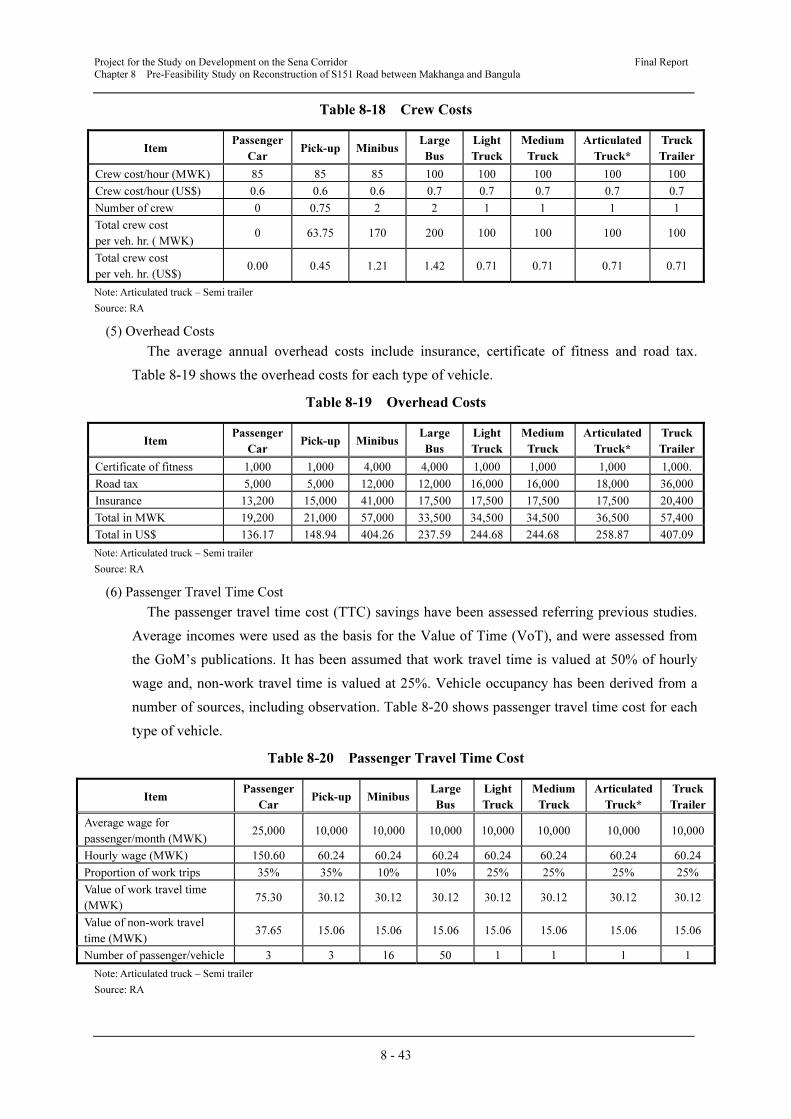
Project for the Study on Development on the Sena Corridor Final Report
Chapter 8 Pre-Feasibility Study on Reconstruction of S151 Road between Makhanga and Bangula
8 - 43
Table 8-18 Crew Costs
Item Passenger
Car Pick-up Minibus
Large
Bus
Light
Truck
Medium
Truck
Articulated
Truck*
Truck
Trailer
Crew cost/hour (MWK) 85 85 85 100 100 100 100 100
Crew cost/hour (US$) 0.6 0.6 0.6 0.7 0.7 0.7 0.7 0.7
Number of crew 0 0.75 2 2 1 1 1 1
Total crew cost
per veh. hr. ( MWK) 0 63.75 170 200 100 100 100 100
Total crew cost
per veh. hr. (US$) 0.00 0.45 1.21 1.42 0.71 0.71 0.71 0.71
Note: Articulated truck – Semi trailer
Source: RA
(5) Overhead Costs
The average annual overhead costs include insurance, certificate of fitness and road tax.
Table 8-19 shows the overhead costs for each type of vehicle.
Table 8-19 Overhead Costs
Item Passenger
Car Pick-up Minibus
Large
Bus
Light
Truck
Medium
Truck
Articulated
Truck*
Truck
Trailer
Certificate of fitness 1,000 1,000 4,000 4,000 1,000 1,000 1,000 1,000.
Road tax 5,000 5,000 12,000 12,000 16,000 16,000 18,000 36,000
Insurance 13,200 15,000 41,000 17,500 17,500 17,500 17,500 20,400
Total in MWK 19,200 21,000 57,000 33,500 34,500 34,500 36,500 57,400
Total in US$ 136.17 148.94 404.26 237.59 244.68 244.68 258.87 407.09
Note: Articulated truck – Semi trailer
Source: RA
(6) Passenger Travel Time Cost
The passenger travel time cost (TTC) savings have been assessed referring previous studies.
Average incomes were used as the basis for the Value of Time (VoT), and were assessed from
the GoM’s publications. It has been assumed that work travel time is valued at 50% of hourly
wage and, non-work travel time is valued at 25%. Vehicle occupancy has been derived from a
number of sources, including observation. Table 8-20 shows passenger travel time cost for each
type of vehicle.
Table 8-20 Passenger Travel Time Cost
Item Passenger
Car Pick-up Minibus
Large
Bus
Light
Truck
Medium
Truck
Articulated
Truck*
Truck
Trailer
Average wage for
passenger/month (MWK) 25,000 10,000 10,000 10,000 10,000 10,000 10,000 10,000
Hourly wage (MWK) 150.60 60.24 60.24 60.24 60.24 60.24 60.24 60.24
Proportion of work trips 35% 35% 10% 10% 25% 25% 25% 25%
Value of work travel time
(MWK) 75.30 30.12 30.12 30.12 30.12 30.12 30.12 30.12
Value of non-work travel
time (MWK) 37.65 15.06 15.06 15.06 15.06 15.06 15.06 15.06
Number of passenger/vehicle 3 3 16 50 1 1 1 1
Note: Articulated truck – Semi trailer
Source: RA

Project for the Study on Development on the Sena Corridor Final Report
Chapter 8 Pre-Feasibility Study on Reconstruction of S151 Road between Makhanga and Bangula
8 - 44
8.5.4 Definition of Cases for Analysis
In the analysis, the cost and the benefit are defined as the difference between “Without the
project” and “With the project” cases. The cases are assumed as follows.
(1) “Without the project” Case (Option-0)
In this case, it has been assumed that no major investment is going to take place; hence
maintenance of the current road network infrastructure would be carried out annually.
In the do nothing case, the existing roads were classified as bumpy, narrow in some parts,
numerous potholes. A certain level of periodic maintenance was assumed, but not upgrading of
the roads.
(2) “With the project” Case (Option-1 and Option-2)
In the “With the project” cases, the project road would be upgraded to a class 1 bitumen
standard with an initial roughness of around 2 mm/km. The project road has three major
components as follows.
• Reconstruction of S151road between Makhanga and Bangula (8.5km)
• Construction of a road bridge at Chiromo
• Construction of a road bridge at Shire
Under the Option-1, it was assumed that the S151 road between Makhanga and Bangula
would be reconstructed at a cost of US$ 14.52 million together with the construction of
Chiromo Road Bridge at a cost of US$ 22.80 million and also the construction of New Shire
Bridge at a cost US$ 19.48 million. The total investment cost is US$ 56.08 million. Under the
Option-2, it was assumed that the S151 road between Makhanga and Bangula would be
reconstructed at a cost of US$ 14.52 million together with the construction of Chiromo Road
Bridge at a cost of US$ 19.48 million. The total cost is US$ 36.60 million.
8.5.5 Results of Economic Evaluation
(1) Results of the Economic Evaluation by HDM-4 model
The main tool used in the economic evaluation was the World Bank’s HDM-4 model. Results
of the main run based on central forecasts for capital costs, maintenance cost, traffic volumes
and vehicle operating costs.
The basic economic requirement for the project to be deemed economically feasible by the
Malawi government is that it should have an EIRR of at least 12% of social discount rate. It
should be pointed out that three engineering options are considered and evaluated and the
results are presented in Table 8-21.
Table 8-21 shows that both engineering solutions are economically viable, however, Option
-2 which includes improvement of S151 road between Makhanga and Bangula, and construction
of only the Chiromo Road Bridge is the highest EIRR value of 50%, compared with Option-1,
which includes improvement of S151 road between Makhanga and Bangula, and construction of
both the Chiromo Road Bridge and the New Shire Bridge with EIRR value of 26.0%.
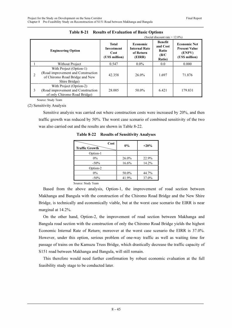
Project for the Study on Development on the Sena Corridor Final Report
Chapter 8 Pre-Feasibility Study on Reconstruction of S151 Road between Makhanga and Bangula
8 - 45
Table 8-21 Results of Evaluation of Basic Options (Social discount rate = 12.0%)
Engineering Option
Total
Investment
Cost
(US$ million)
Economic
Internal Rate
of Return
(EIRR)
Benefit
and Cost
Ratio
(B/C
Ratio)
Economic Net
Present Value
(ENPV)
(US$ million)
1 Without Project 0.547 0.0% 0.0 0.000
2
With Project (Option-1)
(Road improvement and Construction
of Chiromo Road Bridge and New
Shire Bridge)
42.358 26.0% 1.697 71.876
3
With Project (Oprion-2)
(Road improvement and Construction
of only Chiromo Road Bridge)
28.005 50.0% 6.421 179.831
Source: Study Team
(2) Sensitivity Analysis
Sensitive analysis was carried out where construction costs were increased by 20%, and then
traffic growth was reduced by 50%. The worst case scenario of combined sensitivity of the two
was also carried out and the results are shown in Table 8-22.
Table 8-22 Results of Sensitivity Analyses
Cost
Traffic Growth 0% +20%
Option-1
0% 26.0% 22.9%
-50% 16.6% 14.2%
Option-2
0% 50.0% 44.7%
-50% 41.9% 37.0%
Source: Study Team
Based from the above analysis, Option-1, the improvement of road section between
Makhanga and Bangula with the construction of the Chiromo Road Bridge and the New Shire
Bridge, is technically and economically viable, but at the worst case scenario the EIRR is near
marginal at 14.2%.
On the other hand, Option-2, the improvement of road section between Makhanga and
Bangula road section with the construction of only the Chiromo Road Bridge yields the highest
Economic Internal Rate of Return; moreover at the worst case scenario the EIRR is 37.0%.
However, under this option, serious problem of one-way traffic as well as waiting time for
passage of trains on the Kamuzu Truss Bridge, which drastically decrease the traffic capacity of
S151 road between Makhanga and Bangula, will still remain.
This therefore would need further confirmation by robust economic evaluation at the full
feasibility study stage to be conducted later.
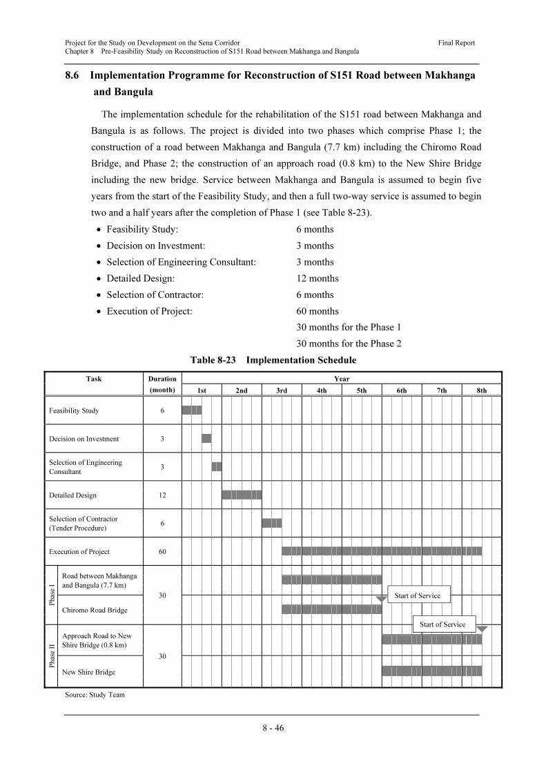
Project for the Study on Development on the Sena Corridor Final Report
Chapter 8 Pre-Feasibility Study on Reconstruction of S151 Road between Makhanga and Bangula
8 - 46
8.6 Implementation Programme for Reconstruction of S151 Road between Makhanga
and Bangula
The implementation schedule for the rehabilitation of the S151 road between Makhanga and
Bangula is as follows. The project is divided into two phases which comprise Phase 1; the
construction of a road between Makhanga and Bangula (7.7 km) including the Chiromo Road
Bridge, and Phase 2; the construction of an approach road (0.8 km) to the New Shire Bridge
including the new bridge. Service between Makhanga and Bangula is assumed to begin five
years from the start of the Feasibility Study, and then a full two-way service is assumed to begin
two and a half years after the completion of Phase 1 (see Table 8-23).
• Feasibility Study: 6 months
• Decision on Investment: 3 months
• Selection of Engineering Consultant: 3 months
• Detailed Design: 12 months
• Selection of Contractor: 6 months
• Execution of Project: 60 months
30 months for the Phase 1
30 months for the Phase 2
Table 8-23 Implementation Schedule
Task Duration
(month)
Year
1st 2nd 3rd 4th 5th 6th 7th 8th
Feasibility Study
6
Decision on Investment
3
Selection of Engineering
Consultant
3
Detailed Design
12
Selection of Contractor
(Tender Procedure)
6
Execution of Project
60
Ph
ase I
Road between Makhanga
and Bangula (7.7 km)
30
Chiromo Road Bridge
Ph
ase I
I
Approach Road to New
Shire Bridge (0.8 km)
30
New Shire Bridge
Source: Study Team
Start of Service
Start of Service

Project for the Study on Development on the Sena Corridor Final Report
Chapter 8 Pre-Feasibility Study on Reconstruction of S151 Road between Makhanga and Bangula
8 - 47
8.7 Overall Evaluation of Reconstruction of S151 Road between Makhanga and
Bangula
Overall evaluation of the reconstruction of S151 road between Makhanga and Bangula
summarized as follows:
(1) Expected Economic Benefits of the Project
The S151 road between Makhanga and Bangula is currently disconnected at the Chiromo
wash away and not functioning as a road for vehicular traffic. Reconstruction of road sections as
well as the construction of two bridges would provide several benefits to the national and local
economy, such as the function of providing alternative arterial road access between the Lower
Shire area the Highland area, that currently depends only on M1 with a steep gradient section.
This function is also very important from the national security point of view to secure a
redundancy of transport route in the Southern Region of Malawi.
Construction of the Chiromo Road Bridge will generate a very positive economic and social
benefits for residents such as to bring and sell agricultural products in Bangula, the ability to
commute to school and better health care services. This would be particularly beneficial to those
living on the eastern side of the New Shire River who have been forced to use an expensive and
risky boat crossing since the disconnection of the S151 in 1997.
(2) Improvement of Road Section between Makhanga and Bangula
For the planning of horizontal and vertical alignment of road section, alternative routes are
compared to minimize the necessity for resettlement of houses and shops, as well as to secure
the function of an all-weather road by sufficient height of embankment to prevent damage to the
road by frequent floods from the Ruo River and the New shire River. The horizontal alignment
in Makhanga area is planned to avoid resettlement of 16 houses/shops near the railway crossing.
Also, a selected alternative route is planned to avoid the high risk from the Ruo River bank
erosion, where the existing road is only 30 m from the continuously eroding river bank.
(3) Construction of the Chiromo Road Bridge
The Chiromo Road Bridge is planned to cross the Chiromo washed away section by the best
horizontal alignment not only from the geometric design point of view, but also to avoid
negative influence on the planned railway line alignment, also proposed in the Study. The type
of structure is selected by comparing structural features, girder height, embankment height and
cost performance. As a result, the Extradosed type 3 spans PC Box Girder Bridge was selected
as the most suitable type.
(4) Construction of the New Shire Bridge
The Shire Bridge is planned to cross the Shire River in parallel with the existing Kamuzu
Truss Bridge, which was originally constructed exclusively as a railway bridge, and converted
into railway-cum-road bridge after installing open grating floors. In order to avoid traffic
confusion on this Kumuzu Truss Bridge after completing the improved road section between
Makhanga and Bangula, and construction of the Chiromo Railway Bridge, as well as

Project for the Study on Development on the Sena Corridor Final Report
Chapter 8 Pre-Feasibility Study on Reconstruction of S151 Road between Makhanga and Bangula
8 - 48
reconstruction of the railway between Makhanga and Bangula, construction of the New Shire
Bridge only for road traffic is evaluated as a priority project for the medium term project after
completion of those components of the road project.
(5) Economic Analysis
In the economic analysis, all the values of the evaluation index are in good standard and this
project is considered to be economically feasible from the viewpoint of the national economy,
even though this is a full scale project, including road improvement as well as construction of
two new bridges.
(6) IEE Results
According to the scoping results of the project, executing the project will generate various
positive impacts particularly for the local economy and social lives of local residents. On the
other hand, negative effects under the environment and social consideration are very limited.
Mitigation measures for these limited negative impacts should be studied in detail when the
horizontal alignment of the road for improvement will be more concrete under the feasibility
study stage.