RC and RL Circuits - Electronics – Online Distance Learning

CHAPTER 7: Response of First-Order
RL and RC Circuits
RL (resistor-inductor)
&
RC (resistor-capacitor)
First order circuits
(voltages and currents are described by first-order differential equations. ).

Introduction
• Our analysis of RL and RC circuits will be divided into three phases.
1. Natural Response: Currents and voltages that arise when stored energy in an
inductor or capacitor is suddenly released to a resistive network.
2. Step Response: Currents and voltages that arise when energy is being acquired
by an inductor or capacitor due to the sudden application of a dc voltage or
current source
3. General Method: Used to find the response of RL and RC circuits to any
abrupt change in a dc voltage or current source
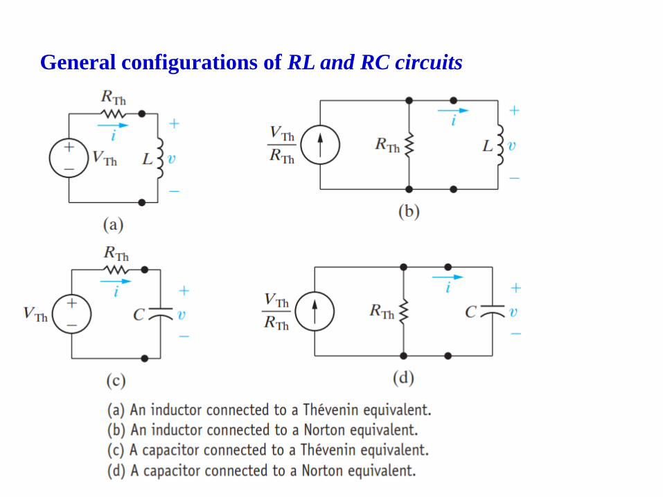
General configurations of RL and RC circuits

7.1 The Natural Response of an RL Circuit
• Switch has been in a closed position for a long time
• All currents and voltages have reached a constant value. Thus only
constant, or dc, currents can exist in the circuit just prior to the switch’s
being opened, and therefore the inductor appears as a short circuit prior to
the release of the stored energy.
• Finding the natural response requires finding the voltage and current at the
terminals of the resistor after the switch has been opened, that is, after the
source has been disconnected and the inductor begins releasing energy.
𝒕 ≥ 𝟎
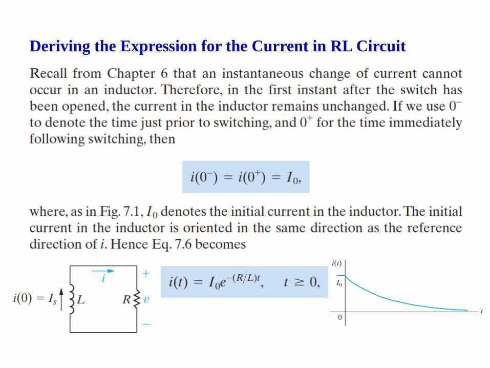
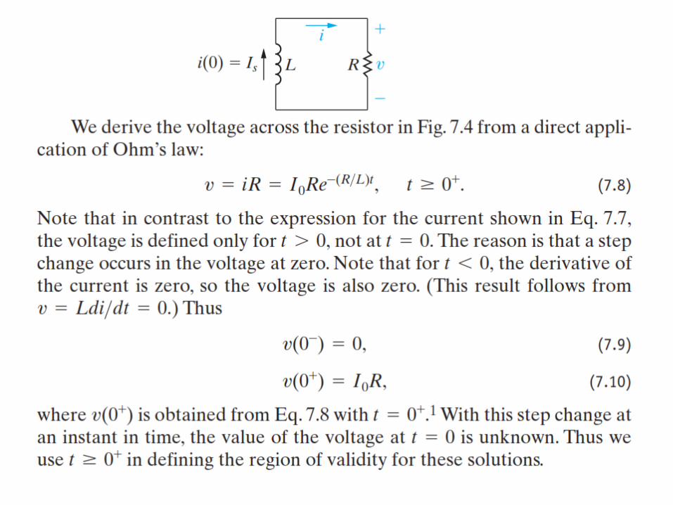
Deriving the Expression for the Current in RL Circuit

Power in RL circuit

Energy in RL circuits
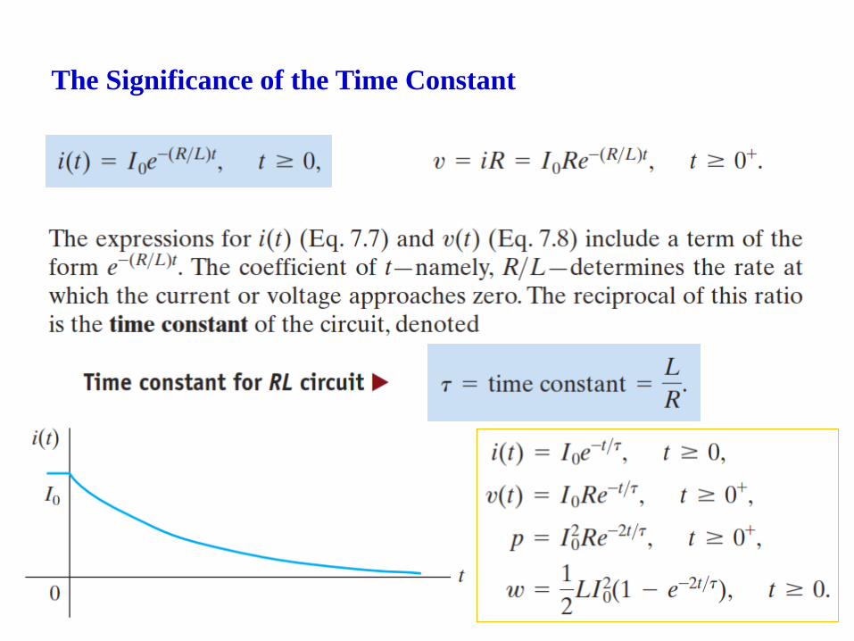
The Significance of the Time Constant

The Significance of the Time Constant
Long Time
Tra
nsi
ent
Res
pon
se
Ste
ad
y-S
tate
Res
pon
se

Calculating the natural response of an RL circuit

7.2 The Natural Response of an RC Circuit
• Switch has been in a closed position for a long time
• All currents and voltages have reached a constant value. Thus only
constant, or dc, currents can exist in the circuit just prior to the switch’s
being opened, and therefore the capacitor appears as open circuit prior to
the release of the stored energy.
• Finding the natural response requires finding the voltage and current at the
terminals of the resistor after the switch has been opened, that is, after the
source has been disconnected and the capacitor begins releasing energy.
𝒕 ≥ 𝟎

Deriving the Expression for the Voltage in RC Circuit

Deriving the Expression for the Voltage in RC Circuit