Chapter 7. 984 Man-Machine Interfaces
35
Chapter 7. 984 Man-Machine Interfaces This chapter identifies and describes the three man-machine interfaces used to program and communicate with the 984 Controller. PI 90 Multi-family Programmer IBM Personal Computer and compatible workstations 964/965 Data Access Panel (DAP) DEC PDP-11 and VAX MAN-MACHINE INTERFACES 7-1
Transcript of Chapter 7. 984 Man-Machine Interfaces

Chapter 7. 984 Man-Machine Interfaces
This chapter identifies and describes the three man-machine interfaces used to program and communicate with the 984 Controller.
PI 90 Multi-family Programmer
IBM Personal Computer and compatible workstations
964/965 Data Access Panel (DAP)
DEC PDP-11 and VAX
MAN-MACHINE INTERFACES 7-1

7-2 MAN-MACHINE INTERFACES

PI 90 Programmer
General Characteristics
Portable
Withstands harsh factory environments
Use on-site or from remote locations
Use with many Modicon Controllers
Provides real time, on-line programming
48K words of user memory
Built-in tape drive
Two RS-232-C ports for serial communications
Support for additional video monitor
Model Pl90-112 for 115v, P190-122 for 220~
Specifications
Physical Dimensions 11 .O in. High x 17.5 in.Wide x 24.0 in. Deep (279 mm x 444.5 mmx 609.6 mm). Weight, 30.0 lb (13.6 kg).
Environmental Operating Temperature, 41 to 104 Degrees F (5 to 40 Degrees C). Storage Temperature, -4 to 140 Degrees F (-20 to 60 De- grees C). Operating Humidity, 20-80% relative humidity, non-condens- ing. Storage Humidity, O-95 % relative humidity, non-condensing.
Power Pl90-112, 95-l 30 Vat, 47-63 Hz, 1OOW. Pl90-122, 190-260 Vat, 47-63 Hz, 1OOW. Fuse, 5 amp No. 57-0041-000.
MAN-MACHINE INTERFACES 7-3

Front Panel
The P190 (figure below) is your primary interface with a programmable controller. It is used to enter, edit, monitor and design user pb~grams. Four main segments make up the front panel of the 190 Programmer:
the tape drive
memory protect keylock
keyboard
cathode ray tube (CRT) display screen
The function of each of these segments is listed on the facing page.
Figure 7-1 P190 Front Panel and Keyboard
SOFTWARE
I
i
__._._.-.-._,
m KEYS ! FUNCTION
_._._ -._.-.
f-‘-‘-‘--‘-’
I NUMERIC 7
KEYS I
7-4 MAN-MACHINE INTERFACES

Display Displays the development of user information.
logic and specific status
Keyboard Divides into four basic groups of keys; the software label keys, the alphabetic keys, the function keys, and the numeric keys. The keyboard and the appropriate software tapes are used to communicate with the programmable controller.
Software Label Keys The functions of these keys are defined by the pro- gram tapes, change with each tape used, and also change at various lev- els within a tape. The figure below shows the main program element menu from the program tape.
Figure 7-2 Software Label Keys
Pressing a Software Label Key on the P190 keyboard will cause the function described by the screen software label just above it to be performed. For example, pressing the leftmost P190 Software Label Key calls for the RELAYS function.
DISPLAY SET
clclclooooo~ SOFTWARE LABEL KEYS
Alphabetic Keys These keys are used to enter messages for the controller’s memory and headers for ladder listings.
Function Keys Enable the operation and control of cursor positioning, formatting, and basic logic functions.
Numeric Keys Permit numeric data entry during P190 operation.
Memory Protect Keyswitch In the UNLOCK position the P190 is in the program mode and you can monitor, configure, and program P190 operations. In the LOCK position, the P190 is in a monitor mode and you can not access any configuration and programming operations.
Tape Drive The buit-in data cartridge tape drive is used to configure, program, and service a Programmable Controller.
MAN-MACHINE INTERFACES 7-5

Rear Panel
The following controls, switches, and other features are located on the rear panel (figure below) of the Pi90 controller.
Figure 7-3 P190 Rear Panel
BRIGHTNESS CONTROL
ON/OFF SWITCH
COMPOSITE VIDEO OUTPUT
I
MODEL & SER,AL
CONTRAST CONTROL NUMBER
/ I
COMMUNICATIONS PARAMETERS CHART
I PORT ONE TO 984 CONTROLLER
PORT TWO PERIPHERAL
PORT PARAMETER
A.C. LINE CONNECTOR
SELECTION SWITCHES (UNDER COVER)
A.C. LINE FUSE
Controls The ON/OFF Power Switch applies power to the P190 in the ON position and shuts off power in the OFF position. The Brightness/Contrast Controls regulate the overall brightness of the display (Brightness Control) and the brightness of the characters on the screen relative to the background (Contrast Control).
7-6 MAN-MACHINE INTERFACES

Power Connection and Fuse AC power is applied to the P190 Programmer through a standard, accessible socket. The fuse is located to the left of port 1. This allows quick and easy fuse checking and replacement. To replace the fuse:
Remove AC Power
Push the fuse casing in and turn it counterclockwise to free the fuse.
Verify that the replacement fuse is proper amperage. Replace fuse.
Push the fuse casing in and turn it clockwise until it is securely in place.
Apply AC power
Composite Video Connector Located next to the ON/OFF switch, this connector allows the use of an external video monitor with the P190. If other video monitors are used, they should have the characteristics shown in the tables below.
Table 7-l
Monitor Specifications
Descriptions Characteristics
Type Signal Video Response Scan Width Horizontal Frequency Vertical Frequency
B/w raster scan EIA RS-170 10 MHz 10% underscan 16,041 Hz (15,750 + 1.8%) 651.4 Hz (non-interlaced)
Table 7-2
Compatible Video Monitors
Some monitors may require magnetic shielding or external mounting of the power transformer to eliminate ‘swim.”
Name Part Number
Panasonic WV531 0 Panasonic WV531 1 Ball Brothers TD 12 Ball Brothers TD 15 Brothers TD 23 Motorola M3560-155
MAN-MACHINE INTERFACES 7-7

Communication Ports Two EIA RS-232 ports allow communication be- tween the P190 and the controller as well as other peripheral devices. Port 1 is used to connect the P190 to the controller, and Port 2 is used to connect the P190 to a printer or other peripheral device. Port parame- ters are set by the parameter selection switches.
Port Parameter Selection Switches Two eight-switch packs are used to set parity, stop bit, and data bit parameters for the two RS-232-C peripheral ports. The switches on the left set parameters for Port 1, and the switches on the right set parameters for Port 2. Baud rates for both ports are set at the factory to 9600 baud.
The switch settings are shown on a parameter selection label which is located to the right of the ports. The figure below shows this label along with the Port 1 and Port 2 switch diagrams. Note that 1 = UP, and 0 = DOWN. Switches must be placed all the way up or all the way down to insure a proper selection.
) NOTE The P190 only reads these switch settings at turn-on.
Figure 74 Port Parameter Selection Switches
FACTORY SET AT 9600 BAUD, EVEN PARITY 1 STOP BIT, 8 DATA BITS.
Yl 1 =UP=py
I YOU SET FOR YOUR PRINTER
dxl O=DOWN=u
7-8 MAN-MACHINE INTERFACES

Cabling
Ports 1 and 2 The figure below shows cable connections and part numbers for connecting the P190 to a printer and a 984 controller. The printer’s port receptacle determines whether the W193-xxx 25pin female connecter or the W194-xxx 25pin male connector cable will be used. The specific 984 controller model to be used determines whether the W907-xxx 25-pin male connecter or the W953-xxx g-pin male connector cable will be used.
Figure 7-5 Ports 1 and 2 Cabling
L(TO 984 PORTS 1,2,3)
MAN-MACHINE INTERFACES 7-9

Composite Video The Composite Video Connector allows the use of an external video monitor with the P190. The figure below shows the cable connections for attaching the P190 to an external video monitor. Note that the hook-up cable (P190 to external video monitor) is USER BUILT. This cable may be constucted using standard RG 75 ohm coaxial cable. Signal attenuation/l00 ft. should be determined against a frequency of 10 Mhz.
Figure 7-6 Composite Video Cabling
BRIGHTNESS CONTROL
I ON/,OFF SWITCH
COMPOSITE VIDEO OUTPl USER BUILT CABLE
r ‘I
CONTRAST CONTROL
.
MODEL & CFRIAI
EXTERNAL VIDEO MONll -OR I
YLI , lAL
NUMBER
COMMUNICATIONS PERIPHERAL
PORT PARAMETER A.C. LINE SELECTION SWITCHES CONNECTOR
A.C. LINE FUSE
JT
7-10 MAN-MACHINE INTERFACES

Remote Station P190 The P190 can be used to program and debug logic at a remote site by using J478 modems, and a number of 4 wire jacks at remote l/O and other strategic locations. See figure below. To use the P190 just plug into the nearest jack and “attach” to the 984.
Figure 7-7 Using the P190 at a Remote I/O Location
/
I/O DROP
SPLITTER
MODEM CONNECTIONS
984 82 OHM TERMINATING RESISTORS
‘4WIRE * JACK -7 l 4WIRE - JACKS
25 FT. DROPS MAX:
BELDEN 8777 *INCLUDING THE CABLE ON THE P190
MAN-MACHINE INTERFACES 7-11

Cable Part Numbers Cable options are summarized in the table below by part number and function. The last three digits of the cable assembly number indicate the cable length.
Table 7-3 P190 Cables
Cable No.
w907-xxx -006 -015 -025 -050 -200
Connects 984A, B, X controllers only, to P190 Programmer
w953-xxx
w191 -xxx
-006 -015 -025
Connects 984 X8X controllers to P190 Programmer
-015 -025 -050
Connects the P190 Programmer to a modem
w 193-xxx -015 Connects the P190 Programmer -025 to a printer (female connector on -050 the printer side)
w 194-xXx -015 Connects the P190 Programmer -025 to a printer (male connector on -050 the printer side)
7-12 MAN-MACHINE INTERFACES

Tapes
Use of Tape Drive The P19O’s memory is loaded from the built in mini-cartridge tape drive. The tape drive is located in the upper right-hand corner of the P190 front panel (see figure below).
Figure 7-8 Pi90 Tape Drive
DRIVE PUCK
/ G.
/ EJkCT
HEAD BUTTON
To load a tape:
1 Open the tape
2 Hold tape with
3 Slide tape into
drive door.
metal plate down, exposed tape facing the drive.
drive and press until it clicks into place.
4 Close the tape drive door.
The first tape inserted after power-up is automatically loaded. All other tapes are loaded by simultaneously pressing the INIT and INIT LOCK keys. Holding down the R key for 2 seconds will cause the P190 to skip the self test and speed the loading.
To remove a tape:
1 Open the tape drive door.
2 Press the eject button (on the right).
MAN-MACHINE INTERFACES 7-13

Master Tapes/Part Numbers The P190 uses specially constructed cassette tapes. Tapes received from Modicon are “master” tapes. They can only be used to create duplicate “working” tapes.
Table 7-4 Master Tapes
All tapes are shown with their most current part number listed first. Revision levels are given for the most current versions only. All part and revision numbers are valid and current as of the date of publication of the P984 Reference Manual.
Iuk
Tape Loader
Programmer
Ascii Programmer
‘Configurator
*Traffic Cop
Utility
3Hot Standby
PID Module
Table to Block Loadable Module
Block to Table Loadable Module
Math Loadable Module
Double Precision Math Loadable Module
Checksum Loadable Module
C988 Loadable DX
5975 Modbus Peer
Drum and Input Compare Loadable
Serial Data Analyzer
Dumb Terminal Tape
P190 Blank Tape
Part NQl
AS-T190-401 301
AS-T984-301 201 001
AS-T984-003
AS-T984-304 204 004
AS-T984-302
AS-T984-305
n I eve1
2.2
2.2
Records user program on tape, loads tape program to controller memory, compares tape program vs. program in controller.
Enters, edits, monitors user logic and accesses Controller Operations.
3.0
3.11
Create, edit, and generate Ascii formatted messages.
Defines communication parameters, allocates memory, and accesses Controller Operations.
3.1
3.0
Specifies reference numbers associated with each t/O slot and type.
Monitors user program, prints ladder listing, and accesses Controller Operations.
AS-T984-210 110
AS-T984-102 101
AS-T984-103
1 .Ol (984-X8X) 1 .O (984-A,B,X)
Switches remote I/O to a back-up 984.
1 .Ol (A,B,X only) 1.0
Enables you to configure, tune or monitor, each of the PID loops.
1.0 (A,B.X only) Data Transfer move (DX) copies 16 bit data word from one memory location to another.
AS-T984-104 1.0 (A,B,X only) Data Transfer move (DX) copies 16 bit data word from one memory location to another.
AS-T984-105 1.0 (A,B,X only) Provides four math functions, square root, process square root, log and anti-log.
AS-T984-108 1.0 (A,B,X only) Provides double precision add, subtract, multiply, and divide functions.
AS-T984-107 1 .O (A,B,X only)
AS-T984-115 1 .O (A,B,X only)
AS-T984-217 1 .O (984-X8X) 117 1 .Ol (984-A,B.X)
AS-T984-220 3.0 (984-A.B,X) 120 1 .O (984-X8X)
AS-T1 90-SDA 2.0
Provides four types of Check-sum calculations: Cyclical Redundancy Checks (CRC), Longitudinal Redundancy Checks (LRC), Straight Check-sum and Binary Addition Check-sum.
Expands 984 problem solving capabiHties with the C986 Coprocessor.
Allows controller to simultaneously write register data to as many as 16 separate controllers via a Modbus II Link.
Simplifies implementation of sequential step orientated logic.
Enables P190 debugging and trbuble-shooting of P453 ASCII, Modbus RS232 communications.
AS-T1 90-ODT 1.0 Allows P190 to emulate dumb terminal.
AS-T190-000 Blank PI90 tape.
‘Configurator tapes AS-T984-204 and 004 contain traffic cop functionality. Configurator tape AS-T984-304 does not. *Traffic Cop tape AS-T984-302 consists of two tapes: Volume 1 and Volume 2. 3Hot Standby tape AS-T984-210 is used.with 680. 685, 780, and 785 controllers only.
7-14 MAN-MACHINE INTERFACES
Back-up Tapes The back-up process involves making a duplicate copy of a tape. The tape to be duplicated must be an original Modicon master.
Back-up copies of original Modicon master tapes MUST be used as working tapes for all P190 functions. The master copies themselves can not be used for controller operations. To back-up an original Modicon master to a working tape:
1 Place the master in the tape drive. Simultaneously press the INIT and the INIT LOCK keys and loading will begin.
2 After about 50 seconds, the REMOVE TAPE prompt appears.
3 Remove the master and the CRT prompts you to LOAD WRITE EN- ABLED SCRATCH TAPE.
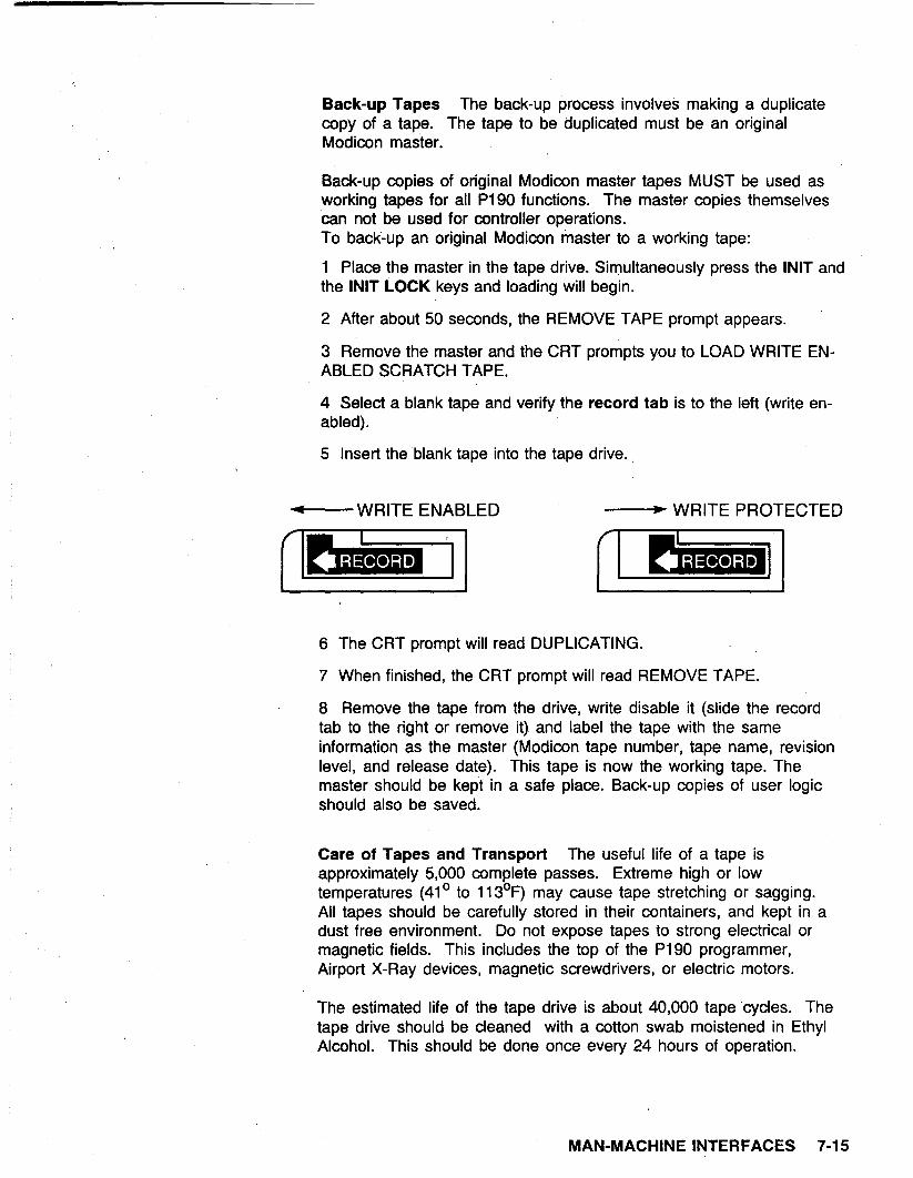
4 Select a blank tape and verify the record tab is to the left (write en- abled).
5 Insert the blank tape into the tape drive.
-WRITE ENABLED - WRITE PROTECTED
1 I I I
6 The CRT prompt will read DUPLICATING.
7 When finished, the CRT prompt will read REMOVE TAPE.
8 Remove the tape from the drive, write disable it (slide the record tab to the right or remove it) and label the tape with the same information as the master (Modicon tape number, tape name, revision level, and release date). This tape is now the working tape. The. master should be kept in a safe place. Back-up copies of user logic should also be saved.
Care of Tapes and Transport The useful life of a tape is approximately 5,000 complete passes. Extreme high or low temperatures (41’ to 113’F) may cause tape stretching or sagging. All tapes should be carefully stored in their containers, and kept in a dust free environment. Do not expose tapes to strong electrical or magnetic fields. This includes the top of the P190 programmer, Airport X-Ray devices, magnetic screwdrivers, or electric motors.
The estimated life of the tape drive is about 40,000 tape ‘cycles. The tape drive should be cleaned with a cotton swab moistened in Ethyl Alcohol. This should be done once every 24 hours of operation.
MAN-MACHINE INTERFACES 7-l 5

Personal Computer
Features
Performs the same functions as the P190
Software works with IBM Personal Computers and compatibles
Use on-site or from remote locations
Provides real time, on-line programming
Specifications
Modicon Executive software for the Personal Computer requires:
256 Kbytes of memory
One floppy and a hard drive or Dual floppy drives
One W-232-C port
MS-DOS 2.1 or greater
Modicon Executive Disk
The 984 software will run on all true compatibles. Other hardware (printer port and printer, hard drive, etc.) is optional.
7-16 MAN-MACHINE INTERFACES

Cabling
IBM XT/AT The figure below shows the cable connections and part numbers for connecting an IBM-XT or AT computer to a 984 controller.
A,B,X controllers using Modicon cable W907-xxx or W807-xxx to connect to an IBM-XT, must have a 25 pin female to female gender changer at the XT’s port. For A,B,X connection to an IBM-AT a 25 to 9 pin female to female gender changer is required at the AT’s port. A parallel printer can be connected to the IBM computer using the parallel port LPTl. This port is located on the back of the computer.
Gender changers are not required for 984-X8X controller cables W955-xxx and W956-xxx.
Figure 7-9 IBM AT, XT Cabling
w955 - P
984-X8X cl u XT m cl
W956
rr AT
F/F GENDER CHANGER
984-A,B,X C XT m i/
W907/807
AT
L F/F GENDER CHANGER
MAN-MACHINE INTERFACES 7-l 7

Keyboard
The Modicon Executive takes advantage of the standard IBM Personal Computer function and keypad keys to perform programming and configuration tasks. The NUM LOCK key must be kept in keypad mode (OFF).
Function Keys The function keys Fl to FlO on the computer keyboard are used to configure and program. Software ,labels are shown on the display screen along with the applicable function key to press. The software lables are mapped to the function keys and are shown on the display screen to aid programming.
Command Keys are Function and Keypad keys that replace P190 keys. The table below shows what key(s) must be pressed for a particular function. When two keys are shown (ALT C for example) they must be pressed simultaneously.
Table 7-5 Command Key Map
ALT C ALT F3 ALT F6 ALT F9 ALT F4 ALT F5 ALT F7 ALT F8 ALT P ALT Fl ESC ALT FlO DEL ALT N ALT F2 PG DN PG UP INS
Function
CHANGE SCREEN CHANGE NODE EXIT RESET SEARCH CONTINUE SEARCH TRACE RETRACE PRINT ERASE CLEAR ERROR CLEAR AR DELETE NODE DELETE NETWORK GET GET NEXT GET PREVIOUS START NEXT
l NOTE When entering numerical data, use only the numeric keys at the top of the computer keyboard.
,
7-18 MAN-MACHINE INTERFACES

Floppy Disks/Part Num bets
The table below lists the application software that is currently available for the personal computer and the 984. All application software is contained on standard 5.25 inch diskettes.
Table 7-6 Floppy Disks
All software titles are shown with their most current pert number listed first. Revision levels are aiven for the most current versions only. Pert end revision numbers are valid end current es of the date of publication of the P984 Reference Manuel.
984 Executive Software AS-DIBM-904
984 Configuretor
984 Traffic Cop
984 Programmer
984 Ascii Message Editor
984 Ladder Lister
984 Annotated Ladder Lister
984 Load/Dump Compare
984 Math and DX Loedable Module
984 PID Loadable Module
964 Hotstandby Loadable Module
984/C986 Loedable DX
984/C986 Utility
Modbus Peer Loadable DX
PID/MMI Assembly Disk
984/Drum and Input Compare Loadeble
AS-DIBM-001
AS-DIBM-902
AS-DIBM-984
AS-DIBM-593
AS-DIBM-905
AS-DIBM-125
AS-DIBM-592
AS-D984-909
AS-D984-701 102
AS-D984-210 110
AS-DIBM-115
AS-DIBM-116
AS-DIBM-217 117
AS-DIBM-118
AS-D984-220 120
1.02
5.1
4.1
4.3
3.0
4.0
2.0
3.2
1 .O (984 A,B,X)
1 .Ol (964 A,B,X) 1 .Ol (984 A,B,X)
1 .Ol (984-X8X) 1 .O (984-A,B,X)
1.0 (A,B,X only)
3.10
1 .o (984-X8X) 1 .Ol (984-A,B,X)
1.0
3.0 (984-A.B,X) 1 .o (984-X8X)
Allows you to Attach, Configure, and Program a 984 controller using a personal computer.
Defines communication parameters, allocates memory, end accesses Controller Operations.
Specifies reference numbers associated with each I/O slot and l/O type;Discrete, BCD, or Binary.
Enters, edits, monitors user logic and accesses Controller Operations.
Create, edit, end generate Ascii formatted messages.
Provides hard copy listing of users logic program.
Prints annotated graphic representations of ladder diagrams.
Loads previously recorded program to 984’s memory, Dumps 984’s memory on to a disc, Verifies that data is loaded/dumped accurately.
Provides four math functions, square root, process square root, log and anti-log.
Enables you to configure, tune or monitor, each of the PID loops.
Switches remote l/O to a beck-up 984.
Expends 984’s problem solving capabilities by accessing the C986 Coprocessor.
Enables configuration, operation, and access to online documentation. Used with 986 Loadable DX.
Allows controller to simultaneously write register data to 16 separate controllers via a Modbus II Link.
Allows you to configure, monitor, end tune 8884 PID Module software.
Simplifies implementation of sequential step orientated logic.
MAN-MACHINE INTERFACES 7-19

Back Up Disks
It is a good practice to maintain back-ups (duplicates) of any data stored on magnetic media. Be sure to make a copy of any orrginal distribution floppies from Modicon before installation. (Consult your controller-DOS or MS-DOS manuals for the correct method of maintaining backup copies.) Any user logic programs should have back-ups maintained. The procedure for doing this is explained in the Load, Record and Verify chapter.
Preparing to use Modicon Executive Software
Before you can install and run any of the Modicon application disks listed in the preceeding table, you must use the 984 Executive Software disk (also listed in table) to display the Executive Menu. Complete procedures for displaying the Executive Menu, selecting options, and installing your Modicon application disks are given in the the Modicon IBM PC Executive Software Manual (GM-HIBM-001). When the installation is complete you can then ATTACH, configure, and program the 984 controller.
7-20 MAN-MACHINE INTERFACES

964/965 Hand-Held Interfaces
Features
Handheld portability
Retains and restores communication parameters
64 character Liquid Crystal Display
Alphanumeric keyboard
Built in connecting cable
Operations
Display status of inputs, coils, and registers
Enable, disable, and force inputs and coils
Display controller memory contents
Modify contents of holding registers
Monitor or alter MODBUS or ASCII port parameters
Automatic determination of controllers port parameters
Display status of controller, including memory-protect, run/stop, attach/de- tach, and controller type
Time delay automatic power down (Conserves battery life)
Configure and troubleshoot communication networks
Stop and start the controller
MAN-MACHINE INTERFACES 7-21

Cabling
Figure 7-10
P964 to 994 Controller 984-A OR 6
The P964 can be used as a simple ASCII terminal as well as a 964 Data
964A or 6 controller ASCII/DAP Port, either directly or through a W903 ASCII/DAP cable. P964
984-A OR I3
Access Panel. The P964 supports the Simple ASCII communications mode only. It can be connected to a
ASCII/DAP ASCII/DAP
El P964 -0
MdDBUS
w903
TO ASCII DEVICE
Figure 7-11 984-A OR B 984-A,B OR X
P965 to 984 Controller I I I I I
1, D
The P965 supports both the Modbus and Simple ASCII communication modes. The P965 can be connected to a 984A or 9848 ASCll/DAP port directly or through a W903 ASCll/DAP cable. The P965 can be connected directly to a Modbus port of a 984A, B or X. Use the Termiflex Adapter Cable part # 97-0209-000 (supplied with the P965 DAP) for connecting to Modbus ports of 984-X8X controllers.
ASCII/DAP
Y.
0 P965 P965
\ -51 I 1 Ml
f TO ASCII DEVICE
MODBUS
PORTS F
984-X8X
Od ;BUS
P965 -t
I ,L,
TERMAFLEX - ADAPTER CABLE
7-22 MAN-MACHINE INTERFACES

Figure 7-12
“” P965 t0 984 Remote ASCII 110
The P965 can be connected to either a J982 or P982 remote ASCII I/O interface. Use the Termaflex Adapter Cable part # 97-0209-000 (supplied with the P965 DAP) for connecting to the P982.
P892
~
TERMAFLEX ADAPTER CABLE
J892
I-
CONNECTION
Keyboard
P964 Keypad There are five groups of keys on the P964 keypad.
Software label keys
Control keys
Display select keys
Alphanumeric keys
Reference operation keys
P965 Keypad There are six groups of keys on the P965 keypad.
On/Off Keys
Software label keys
Control keys
Display select keys
Alphanumeric keys
Reference operation keys
MAN-MACHINE INTERFACES 7-23

Figure 7-13 P964/g55 Keypad
I SOFI’WARE LABEL KEYS
ON(PW5 ONLY)
CONTROL KEYS
OFF(PW5 ONLY)
Es&J DISPLAY SELECT KEYS
I-- REFERENCE OPERATION KEYS
Software Label Keys
Fl, F2, F3, F4 Selects an option shown on the display screen. The function of these keys change with the menu choices displayed. Pressing a key selects the option displayed directly above it.
Alphanumeric Keys
A-F, O-9. and SHIFT These keys are used to enter decimal or hexadecimal data. The SHIFT keys convert decimal keys 1 through 6 on the numeric keypad to hexadecimal A through F. The SHIFT key is pressed before pressing the key with the desired value. The shift action lasts for only one keystroke.
Display Select Keys
REF Selects the active line In a display of more than one reference by positioning a cursor in the leftmost display column. The cursor is initially positioned on the last line of the display and is moved up by the REF key. When the cursor reaches the top line, the REF key causes it to wrap to the last line. Also returns to overview display from detail display.
DETAIL Displays the current line in the detail display format.
DEC/HEX Toggles the data display between decimal and hexadecimal modes.
7-24 MAN-MACHINE INTERFACES

Control Keys
NEW DATA Enter decimal or hexadecimal data from the alphanumeric keys.
NEW REF Clear the displayed reference number or detail display and allow entry of a new reference number.
GET PREV Clear the displayed data and display the previous refer- ence or parameter.
GET NEXT Clear the displayed data and display the next sequential reference or parameter.
ENTER Send newly selected data (reference, parameter, or state) to the controller.
CLEAR Clear displayed data or error message from the display screen. Control remains at the menu level at which the change oc- cured. Valid only for entries requiring the REF or ENTER keys. Also used to clear error or information displays and to return to previous menu.
EXIT Return to previous menu.
Reference Operation Keys
ENABLE/DISABLE Toggle switch that enables or disables a coil or dis- crete input.
FORCE ON Requests that the controller force on a disabled coil or dis- crete input.
FORCE OFF Requests that the controller force off a disabled coil or discrete input.
LEFT ARROW, RIGHT ARROW Selects a specific bit within a detail display of a register.
SET/CLEAR Toggle switch that sets to 1 or clears to 0 a specific bit in a reference. This key is used in conjunction with the left and right arrow keys.
ON/OFF Keys
ON/OFF P965 only. ON turns power on from the internal battery. OFF turns internal battery power off. If power is provided by the port to which the P965 is connected, the ON and OFF keys have no effect.
MAN-MACHINE INTERFACES 7-25

P964 Menu
The software labels that make up the P964 menus are listed in, the table below. The menus allow you to choose operations or parameters. For example, when you select 984, the labels RAP, CMD, and COM are displayed.
When using the P964 in the RAP or COM mode of operation, enter the appropriate data for each parameter then press the ENTER Key. Use the GET NEXT Key to display the next paramater. Pressing the EXIT Key on the P964 returns you to the previous menu.
Table 7- 7 P964 Menu Summary
RAP
I
ENTER
STbP SiRT
J CONF CNCL
,+-i CMDilENU 1
r-L
I I 1 MPl MP2 MP3 APl
- BAiJD ADDRESS
I I
PARITY BAUD I
I PARITY
DATP;’ BITS
I
stoPl B’TS
STOi BITS
MYDE DELAY TIME
CdNF &CL
CMD MENU
7-28 MAN-MACHINE INTERFACES

P964 Menu Selection Descriptions
984
RAP
REF
DET
MEM
CMD
STOP
STRT
COM
MPl
MP2
MP3
APl
TER
CONF
CNCL
Choose controller operations
Invokes RAP menu
Display state or value of entered reference number
Display entered register value in binary plus decimal or hexadecimal. Selector arrow can be used to select a binary bit to set to 1 or 0.
Display entered memory address in binary plus decimal or hexadecimal. Memory addresses range from 300,000 to 365,535 depending on 984 memory size. Display values cannot be altered from the 964.
Invokes COMMAND menu
Issue command to stop controller
Issue command to start controller
Invokes COMMUNICATION menu
Set Modbus port 1 parameters
Set Modbus port 2 parameters
Set Modbus port 3 parameters
Set ASCII port parameters
Invokes ASCII Terminal Mode operation
Confirm ASCII operation request
Cancel ASCII operation request
MAN-MACHINE INTERFACES 7-27

P965 Menus
You can select either DAP, MDAP or TER modes of operation from the power-up display. DAP and TER modes require connection to an ASClI/DAP port. MDAP mode requires connection to a MODBUS port.
DAP Mode In DAP mode the P965 can access controller data and memory, start or stop the controller, or modify communication port parameters, either ASCII or MODBUS. The table below shows the DAP Mode Menu Path.
When using the P965 in the RAP or COM mode of operation, enter the appropriate data for each parameter then press the ENTER Key. Use the GET NEXT Key to display the next parameter. Pressing the EXIT Key on the P965 returns you to the previous menu. Refer to the Modicon P965 Modbus DAP User’s Guide GM-P965-001 Rev-A. for complete connection and operation procedures.
Table 7-8 P905 DAP Mode Menu Path
DAP MDAP TER
1 GO TO J,,,E 7-;co&p ,
RAP CMD COM
ENTER
PARITY
DELAY TIME
CMD MENU
7-28 MAN-MACHINE INTERFACES

965 Menu Selection Descriptions
DAP
RAP
REF
DTL
MEM
CMD
STOP
STRT
COM
MPl
MP2
MP3
APl
TER
CONF
CNCL
Choose controller operations
Invokes RAP menu
Display state or value of entered reference number
Display entered register value in binary plus decimal or hexadecimal. Selector arrow can be used to select a binary bit to set to 1 or 0.
Display entered memory address in binary plus decimal or hexadecimal. Memory addresses range from 300,000 to 365,535 depending on 964 memory size. Display values cannot be altered by the 965.
Invokes COMMAND menu
Issue command to stop controller
Issue command to start controller
Invokes COMMUNICATION menu
Set Modbus port 1 parameters
Set Modbus port 2 parameters
Set Modbus port 3 parameters
Set ASCII port parameters
Invokes ASCII Terminal Mode operation
Confirm ASCII operation request
Cancel ASCII operation request
MAN-MACHINE INTERFACES 7-29
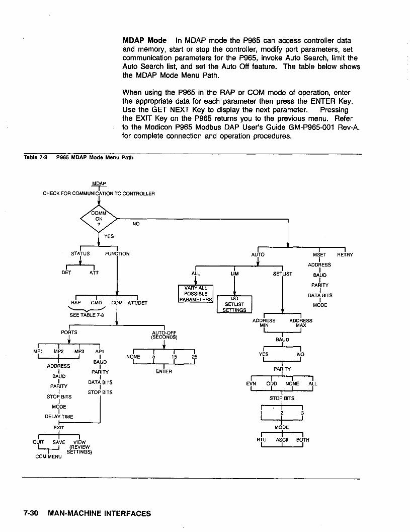
MDAP Mode In MDAP mode the P965 can access controller data and memory, start or stop the controller, modify port parameters, set communication parameters for the P965, invoke Auto Search, limit the Auto Search list, and set the Auto Off feature. The table below shows the MDAP Mode Menu Path.
When using the P965 in the RAP or COM mode of operation, enter the appropriate data for each parameter then press the ENTER Key. Use the GET NEXT Key to display the next parameter. Pressing the EXIT Key on the P965 returns you to the previous menu. Refer to the Modicon P965 Modbus DAP User’s Guide GM-P965-001 Rev-A. for complete connection and operation procedures.
Table 7-9 P965 MDAP Mode Menu Path
MDAP
CHECK FOR COMMUNICATION TO CONTROLLER
NO
I I STATUS FUNCTION
I i I DET All
POkTS
I I I I MPl MP2 MP3 APl
- Ba,D ADDRESS
I I
PARITY BAUD
I I
PARITY ““‘8 BITS I STOP: BITS
STOP BITS I
MODE I
DELAY TIME
I I EXIT
I I I QUIT SAVE VIEW
I I
COM MENU
ti r I I
AUTO MSET RETRY
+ : ADDRESS
ALL Lljb4 SET$T BAUD
ADDAESS ADDit ESS MIN MAX
A”Td-OFF I I (SECONDS) I
BAUD
A I I I
NONE 5
I ENTER
I I 1
YES
4 PARITY
I I I I
“W STOP BITS
+
lf9 MODE
1 I I I
RfU ASCII BdTH
7-30 MAN-MACHINE INTERFACES

P965 MDAP Menu Selection Descriptions
AUTO
ALL
LIM
SETLIST
MSET
RETRY
STATUS
DET
ATT
FUNCTION
COM
Invokes Auto Search menu
Attempts to communicate with controller by varying all possible port parameters
Attempts to communicate with controller by varying a user specified subset of the port parameters (The SETLIST).
Allows you to define a reduced set of MODBUS port parameters for communication with the controller
Sets MODBUS DAP port default parameters I
Attempts to communicate again with controller
Invokes the STATUS display
P965 detached from controller
P965 attached to controller
Invokes MDAP Functions Menu
Invokes COM Menu Display
PORTS
AUTO-OFF
Invokes Set Port Parameters Display
Invokes MDAP Auto Off Display. (Auto Off function, saves battery life by automatically shutting off the P965 after a selected interval of no keyboard activity)
Al-T/DET Toggles between the attached and detached modes
MAN-MACHINE INTERFACES 7-31

Unsupported Communication Parameters
The P965 does not support the following port parameter combinations:
3600 and 7200 Baud The P965 does not communicate at 3600 or 7200 baud. These two baud rates are not included in the Auto Search, Set List, or MSET functions.
On non-connected MODBUS ports (P965 not physically connected) you can read or set baud rates of 3600 or 7200. On connected ports (P965 physically connected) you cannot read or set baud rates of 3600 or 7200.
7-32 MAN-MACHINE INTERFACES

MAN-MACHINE INTERFACES 7-33

DEC PDP-11 and VAX
Modicon 984 software packages are available for the DEC PDP-11 and VAX computer systems. This section identifies and describes the application software contained in these packages. Titles, part numbers, and media information are provided in the accompanying table.
984/DEC PDP-11
DEC-RSX-11 M Documentor Support Module This software package contains two application programs, the Load/Dump/Compare and the Annotated Ladder Lister. The Load/Dump/Compare is an application level Fortran 77 software program that utilizes the Modbus Communications Handler Utility. The Annotated Ladder Lister is a transportable Fortran program that provides comprehensive documentaion of user logic for the 984 series of programmable controllers.
Application Support Module/Modcom II-A This software package contains the Modcom II-A Protocol Handler application program. The Modcom II-A is a Fortran 77 software program that enables a 984 programmable controller to receive a request from the user’s application program and structure it in a Modbus protocol format.
Application Support Module/Modcom II-C This software package contains the Modcom II-C Protocol Handler application program. The Modcom II-C is a C language 984 software program that provides the same purpose and functionality as the Modcom II-A program.
984/DEC VAX
Documentor Support Module This software package contains the same applications as the DEC-RSX-11M package. The only difference is in its format.
Protocol Handler Support Module This software package contains the same application as the Application Support Module/Modcom II-C package. The only difference is in its format.
7-34 MAN-MACHINE INTERFACES

Application Support Module Modcom II-A
Application Support Module Modcom II-C
VAX Documentor Support Module
VAX Protocol Handler Support Module
Table 7-10 DEC PDP-11 and VAX Packaged Software
Title Part No. Media
DEC-RSX-11 M SW-DOSR-11 A 800 BPI Mag Tape Document Support SW-DOS&l 2A 1600 BPI Mag Tape Module SW-DOSR-13A RLOl
SW-DOSR-14A RI02
SW-DOSR-11 A 800 BPI Mag Tape SW-DOSR-12A 1600 BPI Mag Tape SW-DOSR-13A RLOl SW-DOSR-14A RI02
SW-DOSR-11 A 800 BPI Mag Tape SW-DOSR-12A 1600 BPI Mag Tape SW-DOSR-13A RLOl SW-DOSR-14A RI02
SW-DOSV-12Al600 BPI Mag Tape
SW-APPV-12C 1600 BPI Mag Tape
MAN-MACHINE INTERFACES 7-35