Chapter 7-1: H rd r /S ft r CHardware/Software Co-DsinDesign
35
Chapter 7-1: H rd r /S ft r C D si n Hardware/Software Co-Design S Ik Ch Soo-Ik Chae High Performance Embedded Computing 1 Topics Platforms. Performance analysis. Design representations. High Performance Embedded Computing 2
Transcript of Chapter 7-1: H rd r /S ft r CHardware/Software Co-DsinDesign
Chapter 7-1: H rd r /S ft r C D si nHardware/Software Co-Design
S Ik ChSoo-Ik Chae
High Performance Embedded Computing 1
Topicsp
Platforms.
Performance analysis.y
Design representations.
High Performance Embedded Computing 2
Embedded computing systemp g y
Requirements: tight three constraintsL tLow cost
Low power
High performanceHigh performance
These three constraints must be met simultaneously
C d i l ti H d S ftCo-design as a solution: Hardware + Software
High Performance Embedded Computing 3
Design platformsg p
Different levels of integration:PC + board: very low volumey
Custom board with CPU + FPGA or ASIC: lower cost and lower-power.p
Platform FPGA: more expensive than custom chips.p
System-on-chip.
High Performance Embedded Computing 4
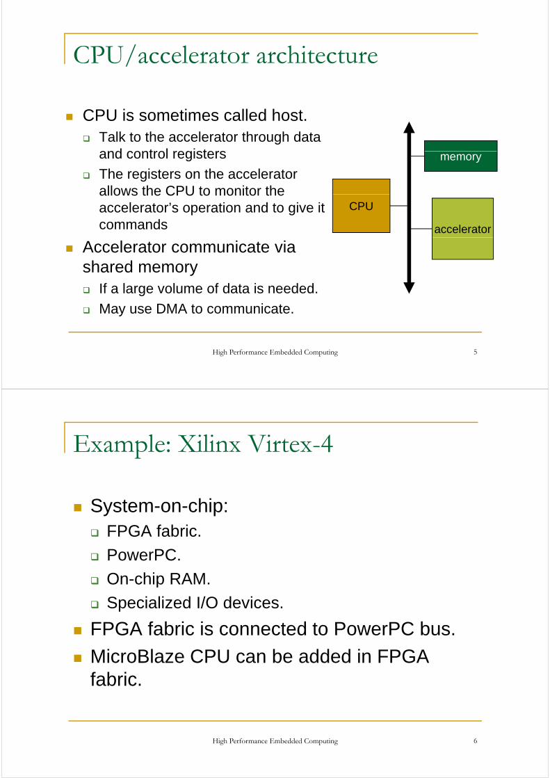
CPU/accelerator architecture/
CPU is sometimes called host.Talk to the accelerator through data and control registersand control registers
The registers on the accelerator allows the CPU to monitor the
memory
allows the CPU to monitor the accelerator’s operation and to give it commands
CPU
accelerator
Accelerator communicate via shared memory
If a large volume of data is needed.
May use DMA to communicate.
High Performance Embedded Computing 5
Example: Xilinx Virtex-4p
System-on-chip:FPGA fabric.
PowerPC.
On-chip RAM.On chip RAM.
Specialized I/O devices.
FPGA fabric is connected to PowerPC busFPGA fabric is connected to PowerPC bus.
MicroBlaze CPU can be added in FPGA fabric.
High Performance Embedded Computing 6
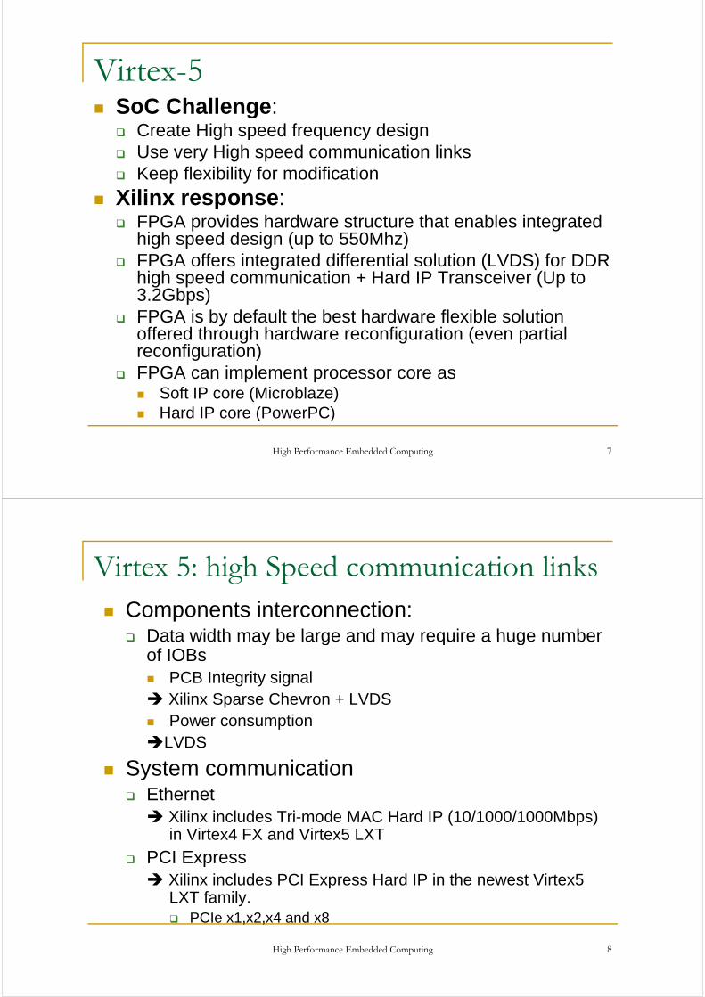
Virtex-5SoC Challenge:
Create High speed frequency designg p q y gUse very High speed communication links Keep flexibility for modification
Xilinx response:Xilinx response:FPGA provides hardware structure that enables integrated high speed design (up to 550Mhz)FPGA offers integrated differential solution (LVDS) for DDR high speed communication + Hard IP Transceiver (Up to 3.2Gbps)p )FPGA is by default the best hardware flexible solution offered through hardware reconfiguration (even partial reconfiguration)g )FPGA can implement processor core as
Soft IP core (Microblaze)Hard IP core (PowerPC)
High Performance Embedded Computing 7
Hard IP core (PowerPC)
Virtex 5: high Speed communication linksComponents interconnection:
Data width may be large and may require a huge number
g p
Data width may be large and may require a huge number of IOBs
PCB Integrity signal Xilinx Sparse Chevron + LVDSPower consumption
LVDSLVDS
System communicationEthernet
Xilinx includes Tri-mode MAC Hard IP (10/1000/1000Mbps) in Virtex4 FX and Virtex5 LXT
PCI ExpressPCI ExpressXilinx includes PCI Express Hard IP in the newest Virtex5 LXT family.
PCI 1 2 4 d 8
High Performance Embedded Computing 8
PCIe x1,x2,x4 and x8

MicroBlaze-Based Embedded Design (Soft IP)
Flexible Soft IPMicroBlaze™32-Bit RISC Core
BRAMLocal Memory
Bus
I-CacheBRAM
Configurable32-Bit RISC Core
Fast Simplex
BusD-CacheBRAM
Sizes
Instruction Data
PowerPC405 Core
Dedicated Hard IP
Instruction Data
PowerPC405 Core
Dedicated Hard IP
PowerPC405 Core
Dedicated Hard IP
PowerPC405 Core
Dedicated Hard IPPossible inVirtex-II Pro
r OPBpLink
0,1….7 Arb
iter
Processor Local Bus
PLBBus
Bridge Arb
iter
Processor Local Bus
PLBBus
BridgeBus
Bridge
Hi-Speed GBe.g.
MHi-SpeedHi-Speed GBGBe.g.
Me.g.
M
Arb
iter OPB
On-Chip Peripheral Bus
UART 10/100E-Net
Memory Controller
CustomFunctions
CustomFunctions
Hi-SpeedPeripheral
GB E-Net
MemoryController
Hi-SpeedPeripheralHi-Speed
PeripheralGB
E-NetGB
E-NetMemory
ControllerMemory
Controller
CacheLink
Off-Chip FLASH/SRAMSRAM
High Performance Embedded Computing 9
Memory
PowerPC-Based Embedded Design (Hard IP)
RocketIO™
PowerPC405 Core
Dedicated Hard IPFlexible Soft IP
DSOCMBRAM
ISOCMBRAM
IBM CoreConnect405 CoreDCR Bus
ArOPBer
Instruction Data
PLBB
on-chip bus standardPLB, OPB, and DCR
rbiter
On-Chip Peripheral Bus
OPB
Arb
ite
Processor Local Bus
PLBBus
Bridge
UART GPIOOn-Chip
PeripheralHi-Speed
PeripheralGB
E-Net
e.g.Memory
Controller
Full system customization to meet performance, functionality, and cost goals
Off-ChipMemory
ZBT SSRAMDDR SDRAM
SDRAM
High Performance Embedded Computing 10
cost goals

Embedded Development Kitp
What is the Embedded Development Kit (EDK)?
The Embedded Development Kit is the XilinxThe Embedded Development Kit is the Xilinx software suite for designing complete embedded programmable systemsp g y
The kit includes all the tools, documentation, and IP that you require for designing systems with y q g g yembedded IBM PowerPC™ hard processor cores, and/or Xilinx MicroBlaze™ soft processor cores
It enables the integration of both hardware and software components of an embedded system
High Performance Embedded Computing 11
Embedded System ToolsyGNU software development tools
C/C++ compiler for the MicroBlaze™ and PowerPC™ processors (gcc)C/C compiler for the MicroBlaze and PowerPC processors (gcc)Debugger for the MicroBlaze and PowerPC processors (gdb)
Hardware and software development toolsB S t B ild Wi dBase System Builder WizardHardware netlist generation tool: PlatGenSoftware library generation tool: LibGeny gSimulation model generation tool: SimGenCreate and Import Peripheral wizardXili Mi D b (XMD)Xilinx Microprocessor Debugger (XMD)Hardware debugging using ChipScope™ Pro Analyzer coresEclipse IDE-based Software Development Kit (SDK)p p ( )Application code profiling toolsVirtual platform generator: VPGenFlash Writer utility
High Performance Embedded Computing 12
Flash Writer utility

Detailed EDK Design Flowg
Standard Embedded Software Flow Standard Embedded Hardware Flow
MHS Filesystem.mhs
Source Code (C code)
MSS File
Source Code(VHDL/Verilog)
Standard Embedded Hardware Flow
Processor IPMPD Files
PlatGenCompile
Object Files LibGen
MSS Filesystem.mss
EDIF
Synthesis
system.ucfFPGA Implementation
(ISE/Xflow)Link
j
Libraries
IP Netlists
Create FPGA Programming (system.bit)
Data2MEMExecutable
Hardware
download.bit
High Performance Embedded Computing 13
Virtex-5 LXT FPGAs
Built on Virtex 5 LX platform 65nm ExpressFabricBuilt on Virtex-5 LX platform 65nm ExpressFabric technology
FPGA industry’s first built-in PCIe & Ethernet blocksFPGA industry s first built in PCIe & Ethernet blocks
Compliance tested at PCISIG Plugfest and UNH IOL
Industry’s lowest power 65nm transceivers: <100mW @Industry s lowest power 65nm transceivers: <100mW @ 3.2Gbps
Support for all major protocols: PCIe, GbE, XAUI, OC-48, pp j p , , , ,etc.
Six devices ranging from 30K to 330K logic cells
High Performance Embedded Computing 14

Virtex summaryyDepending of your Digital system, you may
Xili FPGA th l ti f S tuse Xilinx FPGA as the solution for System On Chip.
Today Xilinx can provide in 1 component (Virtex4 or Virtex5):
Embedded PowerPC 405
Embedded Ethernet MAC 10/100/1000
Embedded MAC DSP
Embedded High Speed Transceivers
E b dd d PCI E (Vi t 5 l )Embedded PCI Express (Virtex5 only)
Programmable Logic Cells
High Performance Embedded Computing 15
….
Example: WILDSTAR II Prop
High Performance Embedded Computing 16
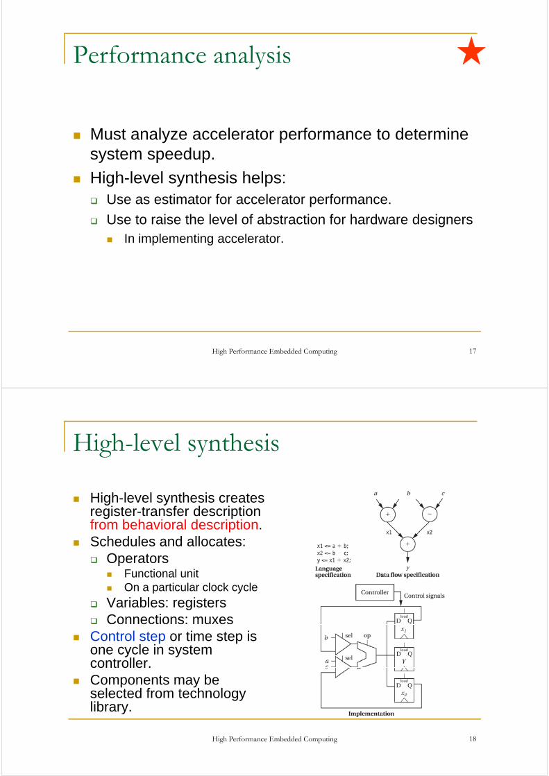
Performance analysisy
Must analyze accelerator performance to determine s stem speed psystem speedup.
High-level synthesis helps:Use as estimator for accelerator performance.
Use to raise the level of abstraction for hardware designersIn implementing acceleratorIn implementing accelerator.
High Performance Embedded Computing 17
High-level synthesisg y
High level synthesis createsHigh-level synthesis creates register-transfer description from behavioral description.S h d l d ll tSchedules and allocates:
OperatorsFunctional unitOn a particular clock cycle
Variables: registersConnections: muxes
Control step or time step is one cycle in system controller.controller.Components may be selected from technology library.
High Performance Embedded Computing 18
library.
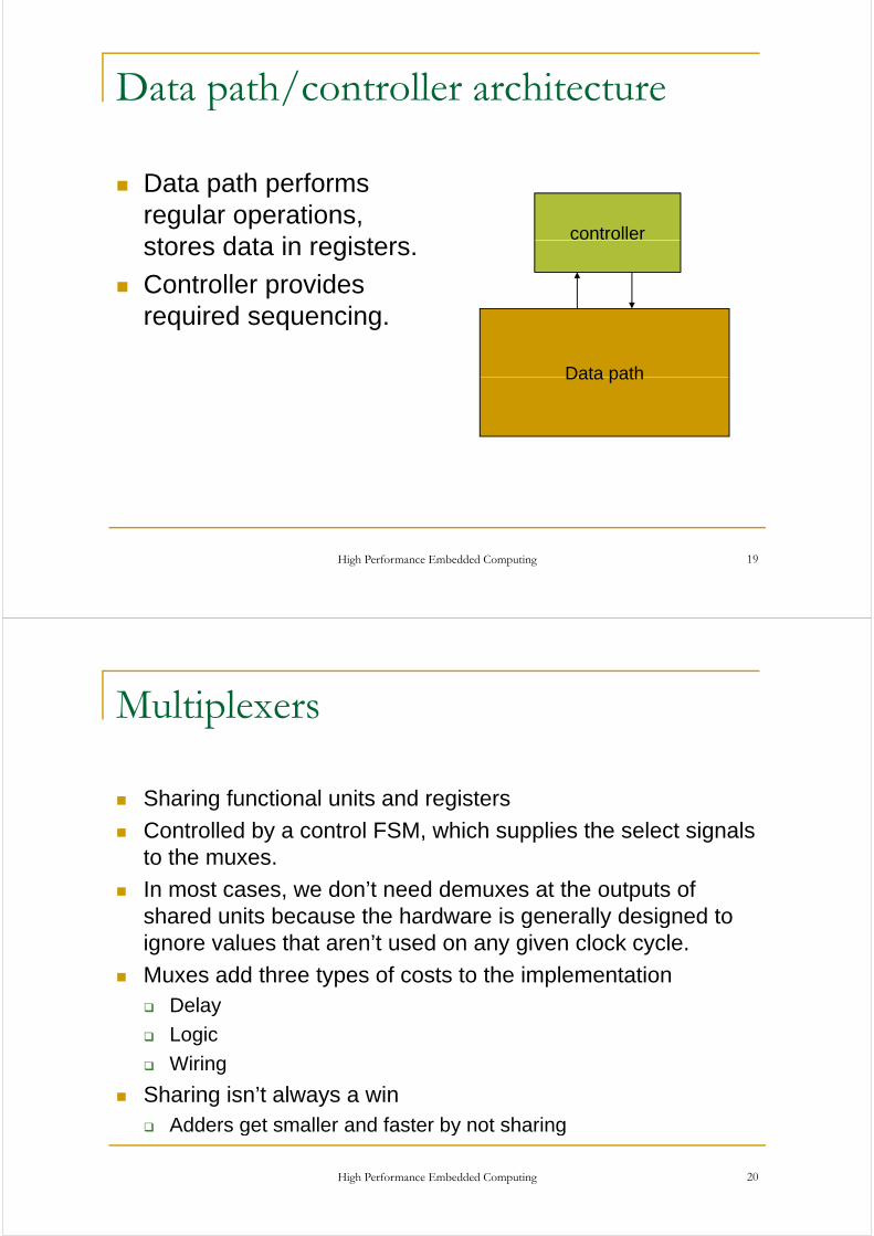
Data path/controller architecturep /
Data path performs regular operations, t d t i i t
controllerstores data in registers.
Controller provides i d irequired sequencing.
Data pathData path
High Performance Embedded Computing 19
Multiplexersp
S fSharing functional units and registers
Controlled by a control FSM, which supplies the select signals to the muxesto the muxes.
In most cases, we don’t need demuxes at the outputs of shared units because the hardware is generally designed to g y gignore values that aren’t used on any given clock cycle.
Muxes add three types of costs to the implementationDelay
Logic
WiringWiring
Sharing isn’t always a winAdders get smaller and faster by not sharing
High Performance Embedded Computing 20
Adders get smaller and faster by not sharing
Models
Model computation as a data flow graph.
Critical path is set of nodes on path that d t i h d ldetermines schedule length.
High Performance Embedded Computing 21
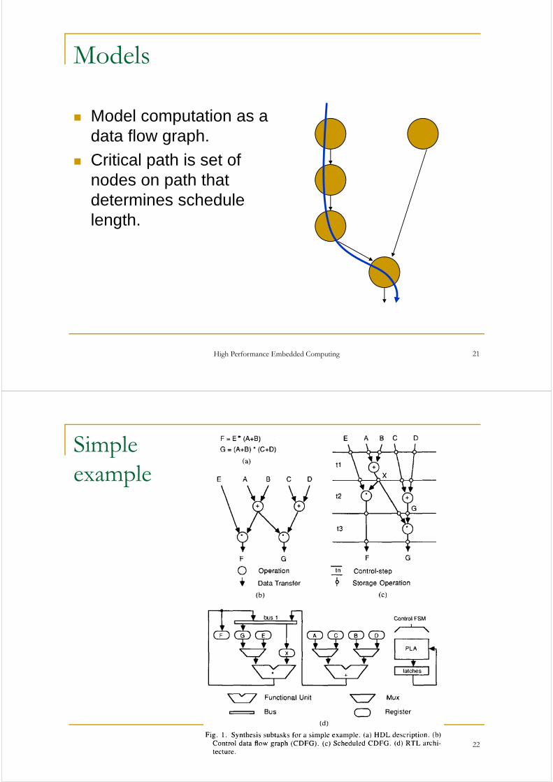
Simple pexample
High Performance Embedded Computing 22
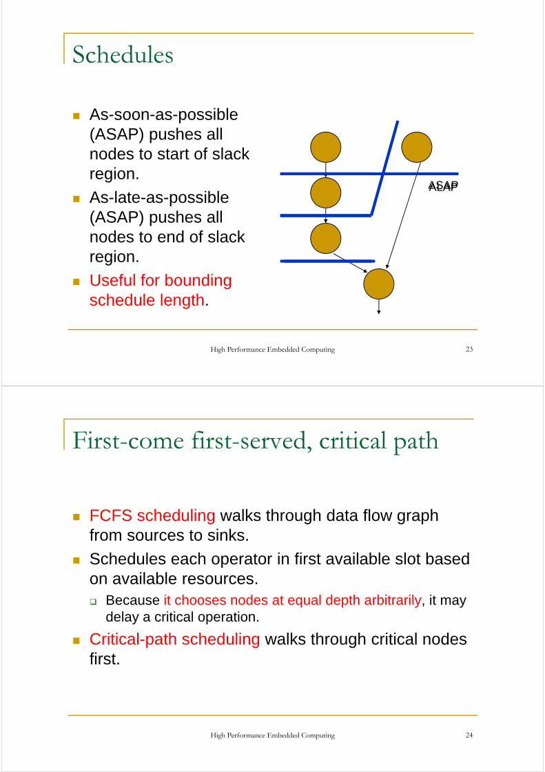
Schedules
As-soon-as-possible (ASAP) pushes all
d t t t f l knodes to start of slack region.
A l t iblASAPALAP
As-late-as-possible (ASAP) pushes all nodes to end of slacknodes to end of slack region.
Useful for boundingUseful for bounding schedule length.
High Performance Embedded Computing 23
First-come first-served, critical path, p
FCFS scheduling walks through data flow graph from sources to sinksfrom sources to sinks.
Schedules each operator in first available slot based on available resourceson available resources.
Because it chooses nodes at equal depth arbitrarily, it may delay a critical operation.delay a critical operation.
Critical-path scheduling walks through critical nodes first.first.
High Performance Embedded Computing 24
List schedulingg
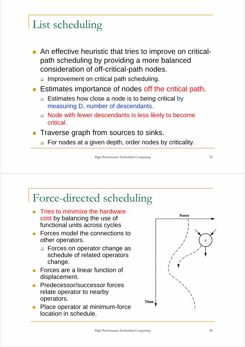
An effective heuristic that tries to improve on critical-path scheduling by providing a more balanced
id ti f ff iti l th dconsideration of off-critical-path nodes.Improvement on critical path scheduling.
E ti t i t f d ff th iti l thEstimates importance of nodes off the critical path.Estimates how close a node is to being critical by measuring D number of descendantsmeasuring D, number of descendants.
Node with fewer descendants is less likely to become critical.
Traverse graph from sources to sinks.For nodes at a given depth, order nodes by criticality.
High Performance Embedded Computing 25
For nodes at a given depth, order nodes by criticality.
Force-directed schedulinggTries to minimize the hardware cost by balancing the use of functional units across cyclesForces model the connections to other operatorsother operators.
Forces on operator change as schedule of related operators hchange.
Forces are a linear function of displacement.pPredecessor/successor forces relate operator to nearby operatorsoperators.Place operator at minimum-force location in schedule.
High Performance Embedded Computing 26

Distribution graphg p
Bound schedule using ASAP, ALAP.
Count number of operators of a given t t h i t itype at each point in the schedule.
W i ht b h lik lWeight by how likely each operator is to be at that time in the schedule.
High Performance Embedded Computing 27
Distribution graphg p
High Performance Embedded Computing 28
Distribution graphg p
High Performance Embedded Computing 29
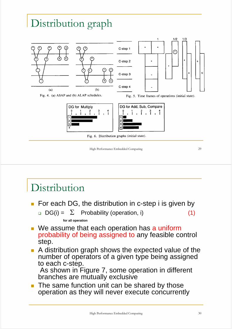
Distribution For each DG, the distribution in c-step i is given by
Σ DG(i) = Σ Probability (operation, i) (1)
We assume that each operation has a uniformfor all operation
We assume that each operation has a uniform probability of being assigned to any feasible control step.A distribution graph shows the expected value of the number of operators of a given type being assigned to each c-stepto each c step.As shown in Figure 7, some operation in different branches are mutually exclusiveTh f ti it b h d b thThe same function unit can be shared by those operation as they will never execute concurrently
High Performance Embedded Computing 30

Distribution graphg p
High Performance Embedded Computing 31
Calculation of self-forcesEach operation of the CDFG will have a self force associated with each c step i of its time frameassociated with each c-step i of its time frame.This is a quantity which reflects the effect of an attempted control step assignment on the overallattempted control step assignment on the overall operation concurrency.It is positive if the assignment causes an increase of p goperation concurrency, and negative for a decrease.The force is much like that exerted by a spring that obeys Hooke’s law.
Force = K * x, x: displacement
E h DG b t d i f iEach DG can be represented as a series of springs ( one for each c-step)
High Performance Embedded Computing 32
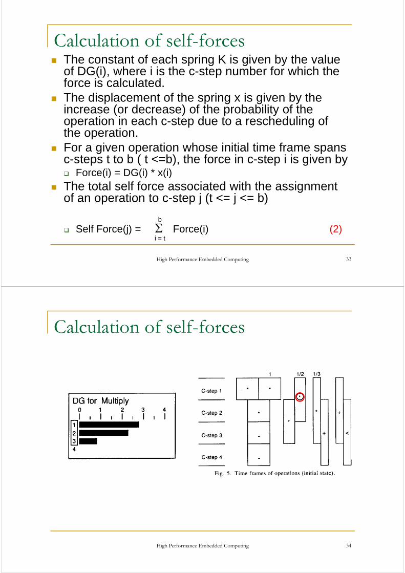
Calculation of self-forcesThe constant of each spring K is given by the value of DG(i), where i is the c-step number for which the f i l l t dforce is calculated.The displacement of the spring x is given by the increase (or decrease) of the probability of theincrease (or decrease) of the probability of the operation in each c-step due to a rescheduling of the operation.F i ti h i iti l ti fFor a given operation whose initial time frame spans c-steps t to b ( t <=b), the force in c-step i is given by
Force(i) = DG(i) * x(i)Force(i) DG(i) x(i)The total self force associated with the assignment of an operation to c-step j (t <= j <= b)
Self Force(j) = Σ Force(i) (2)i = t
b
High Performance Embedded Computing 33
i = t
Calculation of self-forces
High Performance Embedded Computing 34
Calculation of self-forces
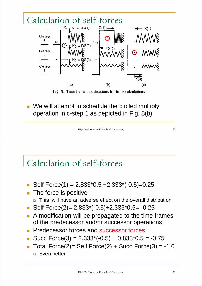
We will attempt to schedule the circled multiply operation in c-step 1 as depicted in Fig. 8(b)
High Performance Embedded Computing 35
Calculation of self-forces
S lf F (1) 2 833*0 5 2 333*( 0 5) 0 25Self Force(1) = 2.833*0.5 +2.333*(-0.5)=0.25The force is positive
Thi ill h d ff t th ll di t ib tiThis will have an adverse effect on the overall distribution
Self Force(2)= 2.833*(-0.5)+2.333*0.5= -0.25A modification ill be propagated to the time framesA modification will be propagated to the time frames of the predecessor and/or successor operationsPredecessor forces and successor forcesPredecessor forces and successor forcesSucc Force(3) = 2.333*(-0.5) + 0.833*0.5 = -0.75Total Force(2)= Self Force(2) + Succ Force(3) = 1 0Total Force(2)= Self Force(2) + Succ Force(3) = -1.0
Even better
High Performance Embedded Computing 36

Summary of force-directed schedulingy g
High Performance Embedded Computing 37
Path-based schedulinggMinimizes the number of control states in controller.
Schedules each path independently, then p p y,combines paths into a system schedule.
Schedule path combinations using minimumSchedule path combinations using minimum clique covering.
Al k f t ibl (AFAP)Also known as as-fast-as-possible (AFAP) scheduling
High Performance Embedded Computing 38

Path-based schedulingg
High Performance Embedded Computing 39
Path-based schedulingg
High Performance Embedded Computing 40

Path-based schedulingg
High Performance Embedded Computing 41
AFAP Schedulingg
High Performance Embedded Computing 42

AFAP scheduling of a pathg p
The ideaThe ideaFind all longest pathsThen compute the constraints for each pathe co pute t e co st a ts o eac patSchedule each path AFAP independently.
A path corresponds to one possible execution sequenceSo, the number of different paths is a measure of how many different functions a design can performhow many different functions a design can perform.Although the number of paths in a graph can grow worse than exponentially, in practice we have found
th d f 1000 th f th ti it fon the order of 1000 paths for the execution unit of a microprocessor.
High Performance Embedded Computing 43
Path
Path1 = {1 2 3 4 5 6 7 8 9 10}Path1 = {1,2,3,4,5,6,7,8,9,10}Path2 = {1,2,3,4,6,7,8,9,10}Path3 = {7 8 9 10}Path3 {7,8,9,10}Note that path that starts at loop beginning vF must also be considered.
High Performance Embedded Computing 44

Constraints
Variables can be assigned only once in one control t tstate.
IO ports can be read or written only once in one control statecontrol stateFunctional units can be used only once in a control stateThe maximal delay within one control state limits the number of operations that can be chained.The amount of storage and communication (busesThe amount of storage and communication (buses, muxes) is not constrained presently.Obviously storage and communication can beObviously storage and communication can be optimized during allocation.Constraints are kept as sets of operation {vi}
High Performance Embedded Computing 45
Constraints and Interval graphg pVariables can be assigned only once in one control state.IO ports can be read or written only once in one controlIO ports can be read or written only once in one control stateFunctional units can be used only once in a control stateFunctional units can be used only once in a control stateThe maximal delay within one control state limits the number of operations that can be chained.pThe amount of storage and communication (buses, muxes) is not constrained presently.Obviously storage and communication can be optimized during allocation.Constraints are kept as sets of operation {vi}
If any v in {vi} is the first operation in the next state, the constraint is met
High Performance Embedded Computing 46
constraint is met.

Interval graph and Clique g p q
Th i t l h f th t f t i t f hThe interval graph for the set of constraints of each path is formed
A d i i li i i dAnd a minimum clique covering is computed.
In the interval graph each node corresponds to an interval and edges indicate that the corresponding tow intervals overlaps. A clique is a complete
b h ith ll ibl dsubgraph with all possible edges.
A minimum clique covering (NP-complete in general) i i i l b f li th t h d iis a minimal number of cliques, so that each node is in one clique.
High Performance Embedded Computing 47
Constraints and Interval graphg p
High Performance Embedded Computing 48
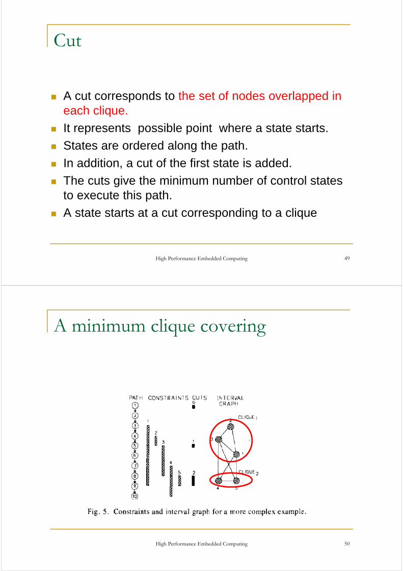
Cut
A cut corresponds to the set of nodes overlapped in each cliqueeach clique.
It represents possible point where a state starts.
St t d d l th thStates are ordered along the path.
In addition, a cut of the first state is added.
The cuts give the minimum number of control states to execute this path.
A state starts at a cut corresponding to a clique
High Performance Embedded Computing 49
A minimum clique coveringq g
High Performance Embedded Computing 50

Overlapping of paths pp g p
To find the minimum number of states for all paths, the schedule for each path must be overlappedthe schedule for each path must be overlapped.
Define another graphNodes: cutsNodes: cuts
Edges: join nods corresponding to overlapping cuts
Find a minim clique of this new graphFind a minim clique of this new graphGives the minimum set of cuts that fulfills the fastest schedule for each path and thus the minimum number ofschedule for each path, and thus the minimum number of control states.
High Performance Embedded Computing 51
Minimum number of control states
High Performance Embedded Computing 52
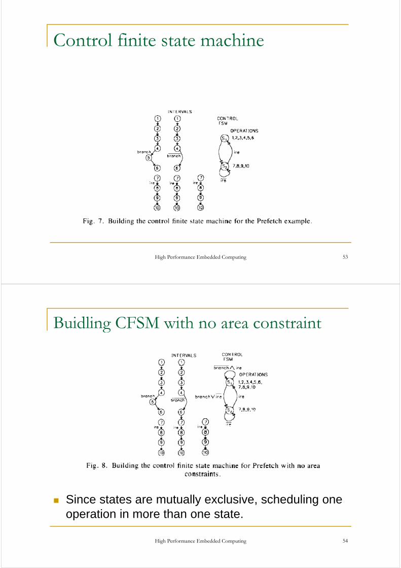
Control finite state machine
High Performance Embedded Computing 53
Buidling CFSM with no area constraintg
Since states are mutually exclusive, scheduling one operation in more than one state.
High Performance Embedded Computing 54
p

Accelerator estimation
E ti ti th h d t f l tEstimating the hardware cost of an accelerator requires balancing accuracy and efficiency.
E ti ti t b d h t idEstimation must be good enough to avoid misguiding the overall synthesis process.
B t th ti t t b t d i klBut the estimates must be generated quickly enough that co-synthesis can explore a large number of candidate designsnumber of candidate designs.
They just rely on scheduling and allocation to measure execution time and hardware sizemeasure execution time and hardware size.
High Performance Embedded Computing 55
Accelerator estimation
How do we use high-level synthesis, etc. to estimate the performance of an accelerator?the performance of an accelerator?
We have a behavioral description of the accelerator functionfunction.
Need an estimate of the number of clock cycles.
Need to evaluate a large number of candidateNeed to evaluate a large number of candidate accelerator designs.
Can’t afford to synthesize them allCan t afford to synthesize them all.
High Performance Embedded Computing 56

Estimation methods
Hermann et al. used numerical methods.Estimated incremental costs due to adding blocks gto the accelerator.
Henkel and Ernst used path-basedHenkel and Ernst used path based scheduling.
Cut CFDG into subgraphs: reduce loop iterationCut CFDG into subgraphs: reduce loop iteration count; cut at large joins; divide into equal-sized pieces.pieces.
Schedule each subgraph independently.
High Performance Embedded Computing 57
Single- vs. multi-threadedg
One critical factor is available parallelism:single-threaded/blocking: CPU waits for g gaccelerator;
multithreaded/non-blocking: CPU continues to gexecute along with accelerator.
To multithread, CPU must have useful workTo multithread, CPU must have useful work to do.
But software must also support multithreadingBut software must also support multithreading.
High Performance Embedded Computing 58

Total execution time
Single-threaded: Multi-threaded:
P1 P1
P2 A1 P2 A1
P3 P3
P4 P4
High Performance Embedded Computing 59
Execution time analysisy
Single-threaded:Count execution time of all component processes
Multi-threaded:Find longest path through executionall component processes. through execution.
High Performance Embedded Computing 60

Hardware-software partitioningp g
Partitioning methods usually allow more than one g yASIC.
Typically ignore CPU memory traffic in bus yp y g yutilization estimates.
Typically assume that CPU process blocks while yp y pwaiting for ASIC.
mem
CPU
ASIC
CPU
ASIC
High Performance Embedded Computing 61
Co-design activities gScheduling operations, including communication on the network and computation on the PEs: make surethe network and computation on the PEs: make sure that data is available when it is needed.Allocation computation to PE: make sure thatAllocation computation to PE: make sure that processes don’t compete for the PE.Partitioning functional description into computation g p punits: break operations into separate processes to increase parallelism; put serial operations in one
t d i tiprocess to reduce communication.Mapping: take abstract PEs and communication links onto specific components; mapping selectslinks onto specific components; mapping selects specific components that can be associated with more precise cost, performance, and power
High Performance Embedded Computing 62
p , p , p

Scheduling and allocation
Must schedule/allocate
P1P2
computation
communication
P1
P3communication
Performance may vary greatly withvary greatly with allocation choice.
P1 P3P1 P2 P3
CPU1ASIC1
High Performance Embedded Computing 63
/Problems in scheduling/allocationCan multiple processes execute concurrently?
Is the performance granularity of available components fine enough to allow efficient search of the solution space?
Do computation and communication requirements conflict?
How accurately can we estimate performance?software
custom ASICs
High Performance Embedded Computing 64

Partitioning example
r = p1(a,b);
r=p1(a,b); s=p2(c,d);
r p1(a,b);s = p2(c,d);
z = r + s;
z = r + s
beforeft
z r s
after
High Performance Embedded Computing 65
Problems in partitioning
At what level of granularity must partitioning be performed?
How well can you partition the system without an allocation?an allocation?
How does communication overhead figure into partitioning?into partitioning?
High Performance Embedded Computing 66

Problems in mapping
Mapping and allocation are strongly connected when the components vary widely in performance.
Software performance depends on busSoftware performance depends on bus configuration as well as CPU type.
Mappings of PEs and communication linksMappings of PEs and communication links are closely related.
High Performance Embedded Computing 67
Program representationsg p
CDFG: single-threaded, executable, can extract some parallelism.
Task graph: task-level parallelism, no operator-level detailoperator level detail.
TGFF (task graph for free) generates random task graphsgraphs.
UNITY: based on parallel programming llanguage.
High Performance Embedded Computing 68
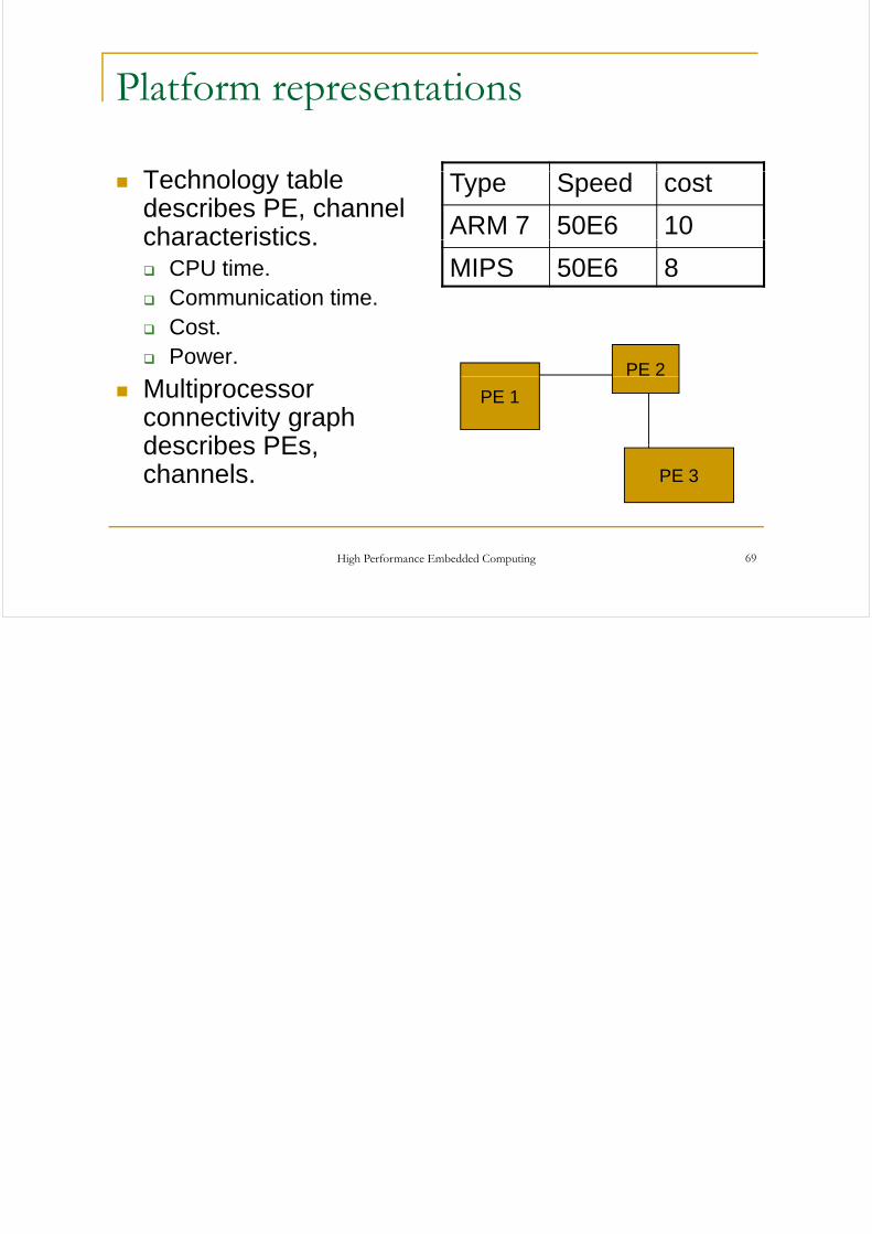
Platform representationsp
T h l t blTechnology table describes PE, channel characteristics
Type Speed cost
ARM 7 50E6 10characteristics.CPU time.Communication time.
MIPS 50E6 8
Cost.Power.
PE 2Multiprocessor connectivity graph describes PEs
PE 1
describes PEs, channels. PE 3
High Performance Embedded Computing 69