CHAPTER 6mfrs.govmu.org/English/Publications/Fire Code... · Chapter 6 - 9 EXPLANATIONS &...
130
Chapter 6 - 1 CHAPTER 6 6.1 PORTABLE EXTINGUISHERS 6.1.1 General (a) All Purpose Groups, except Purpose Groups I shall be provided with portable fire extinguishers. (b) Portable fire extinguishers where required to be provided shall be constructed in conformity with specifications stipulated under BS EN 3 Specifications for Portable Fire Extinguishers. (c) All portable fire extinguishers where required to be provided shall be charged, tested and maintained in fully operational conditions and properly tagged in conformity with requirements in BS EN 3 Code of Practice for Use and Maintenance of Portable Fire Extinguishers. EXPLANATIONS & ILLUSTRATIONS No illustration. Cl.6.1.1 (a) specifically precludes residential floors under purpose group I from the need to provide portable fire extinguishers. However, in a block of residential apartments, one would expect to find rooms or spaces designed for such use as electrical switch rooms, transformer rooms, generator rooms, lift motor rooms, general store rooms, etc. For such spaces or rooms, fire extinguishers of suitable type and capacity should be provided to take care of any outbreak of incipient fire. Although it is not a requirement that kitchen of each apartment or maisonette unit should be provided with a fire extinguisher, every owner should, for his family safety, install a multi-purpose 4 kg dry chemical type or 2 Kg carbon dioxide type fire extinguisher. Once a fire extinguisher has been installed in a building, it becomes the responsibility of the building owner to maintain it. (a) periodically inspecting each extinguisher; (b) recharging each extinguisher following discharge; and (c) performing hydrostatic tests as required. Maintenance of fire extinguisher shall only be carried out by approved servicing agency or company. Maintenance shall be carried out periodically, but at least once a year. A maintenance check covers the disassembling of the extinguisher, examine all its parts, cleaning and replacing any defective parts, and reassembling, recharging the extinguisher
Transcript of CHAPTER 6mfrs.govmu.org/English/Publications/Fire Code... · Chapter 6 - 9 EXPLANATIONS &...

Chapter 6 - 1
CHAPTER 6 6.1 PORTABLE EXTINGUISHERS
6.1.1 General
(a) All Purpose Groups, except Purpose Groups I shall be provided with portable fire
extinguishers. (b) Portable fire extinguishers where required to be provided shall be constructed in conformity
with specifications stipulated under BS EN 3 Specifications for Portable Fire Extinguishers. (c) All portable fire extinguishers where required to be provided shall be charged, tested and
maintained in fully operational conditions and properly tagged in conformity with
requirements in BS EN 3 Code of Practice for Use and Maintenance of Portable Fire
Extinguishers.
EXPLANATIONS & ILLUSTRATIONS
No illustration.
Cl.6.1.1 (a) specifically precludes residential floors under purpose group I from the need to provide portable
fire extinguishers. However, in a block of residential apartments, one would expect to find rooms or spaces
designed for such use as electrical switch rooms, transformer rooms, generator rooms, lift motor rooms,
general store rooms, etc. For such spaces or rooms, fire extinguishers of suitable type and capacity should be
provided to take care of any outbreak of incipient fire. Although it is not a requirement that kitchen of each apartment or maisonette unit should be provided with a
fire extinguisher, every owner should, for his family safety, install a multi-purpose 4 kg dry chemical type or 2
Kg carbon dioxide type fire extinguisher. Once a fire extinguisher has been installed in a building, it becomes the responsibility of the building owner to
maintain it. (a) periodically inspecting each extinguisher;
(b) recharging each extinguisher following discharge; and
(c) performing hydrostatic tests as required.
Maintenance of fire extinguisher shall only be carried out by approved servicing agency or company.
Maintenance shall be carried out periodically, but at least once a year. A maintenance check covers the
disassembling of the extinguisher, examine all its parts, cleaning and replacing any defective parts, and
reassembling, recharging the extinguisher

Chapter 6 - 2
CHAPTER 6
6.1 PORTABLE EXTINGUISHERS 6.1.2 Type, size and siting
Classification of portable fire extinguishers provided shall be selected in accordance with criteria
specified under BS EN 3 such that the nature of processes and contents within the building concerned
can be effectively protected. The size, quantity and siting of these portable fire extinguishers shall
comply with the requirements in BS EN3 under the respective class of occupancy hazard.
EXPLANATIONS & ILLUSTRATIONS
Diagram 6.1.2
The type, size, quantity and siting of the portable fire extinguishers shall comply with the requirements in BS
EN 3.
Chapter 6 - 3
EXPLANATIONS & ILLUSTRATIONS 6.1.2
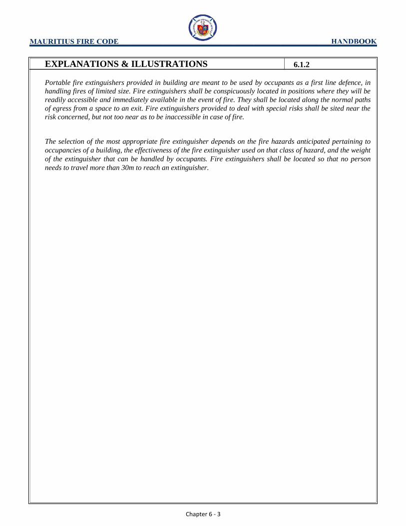
Portable fire extinguishers provided in building are meant to be used by occupants as a first line defence, in
handling fires of limited size. Fire extinguishers shall be conspicuously located in positions where they will be
readily accessible and immediately available in the event of fire. They shall be located along the normal paths
of egress from a space to an exit. Fire extinguishers provided to deal with special risks shall be sited near the
risk concerned, but not too near as to be inaccessible in case of fire.
The selection of the most appropriate fire extinguisher depends on the fire hazards anticipated pertaining to
occupancies of a building, the effectiveness of the fire extinguisher used on that class of hazard, and the weight
of the extinguisher that can be handled by occupants. Fire extinguishers shall be located so that no person
needs to travel more than 30m to reach an extinguisher.
Chapter 6 - 4
CHAPTER 6
6.1 PORTABLE EXTINGUISHERS
6.1.3 Installation, marking
Portable fire extinguishers provided shall be installed and conspicuously marked in accordance with
requirements by BS EN 3.
EXPLANATIONS & ILLUSTRATIONS
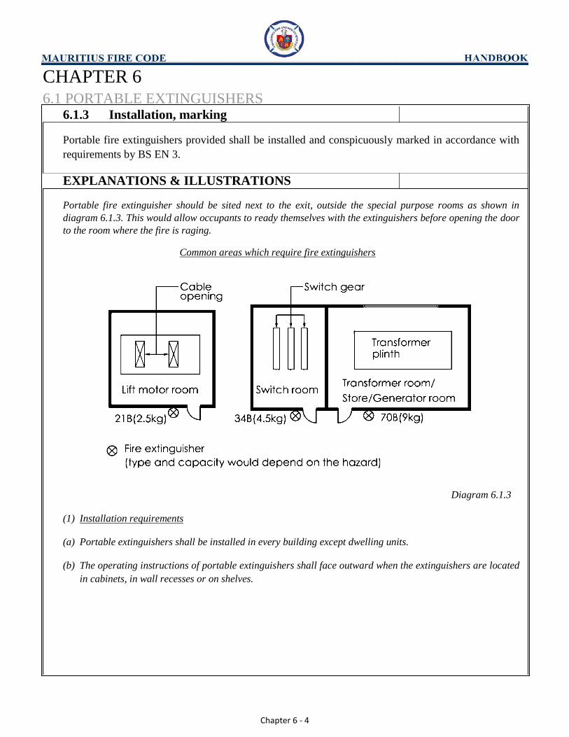
Portable fire extinguisher should be sited next to the exit, outside the special purpose rooms as shown in
diagram 6.1.3. This would allow occupants to ready themselves with the extinguishers before opening the door
to the room where the fire is raging.
Common areas which require fire extinguishers
Diagram 6.1.3
(1) Installation requirements
(a) Portable extinguishers shall be installed in every building except dwelling units.
(b) The operating instructions of portable extinguishers shall face outward when the extinguishers are located
in cabinets, in wall recesses or on shelves.
Chapter 6 - 5
CHAPTER 6
6.2 RISING MAIN AND HOSE REEL SYSTEM
6.2.1 Type of Rising Main
(a) The type of rising main system shall be provided appropriate to the building as follows:
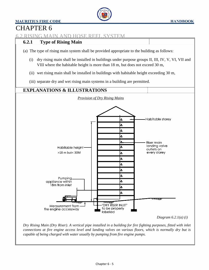
(i) dry rising main shall be installed in buildings under purpose groups II, III, IV, V, VI, VII and
VIII where the habitable height is more than 18 m, but does not exceed 30 m,
(ii) wet rising main shall be installed in buildings with habitable height exceeding 30 m, (iii) separate dry and wet rising main systems in a building are permitted.
EXPLANATIONS & ILLUSTRATIONS
Provision of Dry Rising Mains
Diagram 6.2.1(a) (i)
Dry Rising Main (Dry Riser). A vertical pipe installed in a building for fire fighting purposes, fitted with inlet
connections at fire engine access level and landing valves on various floors, which is normally dry but is
capable of being charged with water usually by pumping from fire engine pumps.
>18 m but< 30M

Chapter 6 - 6
EXPLANATIONS & ILLUSTRATIONS 6.2.1(a)
Dry rising mains are basically dry water pipes. The empty mains need to be charged with water through the breeching inlets by fire appliance. The dry rising mains should not exceed 30m to avoid excessive pumping pressure. Generally, building with a small foot print and the riser stack is located at the perimeter wall of the building,
there is no need to provide landing valve at 1st
storey level. However, if the riser stack is located deep inside
the building as shown in diagram 6.2.1(a)(i), then landing valve is required to be provided at 1st
storey level.

Chapter 6 - 7
EXPLANATIONS & ILLUSTRATIONS 6.2.1(a)(iii)
Separate dry and wet rising main system
Diagram 6.2.1(a) (iii)
Where a block of residential building has podium and tower blocks integrated
(1) Tower block exceeding 30m in habitable height shall be provided with wet rising main.
(2) Podium block needs to be provided with dry rising main only.
>30 M
>18 M

Chapter 6 - 8
(b) Notwithstanding the requirements in sub-clause (a), dry rising main conforming to BS 9990 shall
be provided to any part of a single or multiple level basements.
Diagram 6.2.1(b)-1
All basements except those under Purpose Group I are required to be covered by dry rising main, irrespective
of the depth and number of basements below ground level. Rising main would help to provide steady supply of
water required by fire fighters during emergency. The provision would eliminate the tedious process of laying
fire hoses from ground level into the basement floors to tackle any outbreak of fire.
Where breeching inlets are provided at the foot of the riser stack, landing valve for Purpose Group II is not
required to be provided at the 1st
storey level.
EXPLANATIONS & ILLUSTRATIONS 6.2.1

Chapter 6 - 9
EXPLANATIONS & ILLUSTRATIONS 6.2.1(b)
Rising main in basements
Diagram 6.2.1(b)-2
Diagram 6.2.1(b)-3
All basements except those under Purpose Group I are required to be covered by dry rising main, irrespective
of the depth and number of basements below ground level. Rising main would help to provide continuous
supply of water required by fire fighters during emergency. The provision would eliminate the tedious process
of laying fire hoses from ground level into the basement floors to tackle any outbreak of fire.
18M < Habitable height
<30M
18M < Habitable height
<30M

Chapter 6 - 10
(c) Where the building has access from more than one ground level or road level, the height measurements for the purpose of this code shall be taken from the level of access way or fire engine access road (applicable to buildings under purpose group II) provided.
EXPLANATIONS & ILLUSTRATIONS 6.2.1
Type of Rising Mains to be installed in high rise buildings
Diagram 6.2.1(c)
(1) For the purpose of determining the provision of rising main to an apartment or maisonette building, the
habitable height shall be taken from the level of the lowest fire engine access way or fire engine access
road where breeching inlets are provided. (2) Dry rising mains are basically dry water pipes. The empty mains need to be charged with water through
the breeching inlets by fire engines. The dry rising mains should not exceed 30m in height to avoid
excessive pumping pressure. (3) Wet rising mains are constantly charged with water that provide the required flow rate and pressure for
fire fighting and equipped with water storage capacity for a given duration of 60 mins. The breeching
inlets, usually provided at ground level, are meant for replenishing the water tank.
Hab
itab
le H
eigh
t ab
ove
30
M
Hab
itab
le H
eigh
t B
etw
een
18
M &
30
M
Chapter 6 - 11
CHAPTER 6
6.2 RISING MAIN AND HOSE REEL SYSTEM
6.2.2 Number, Location and Size of Rising Mains
(a) The number and distribution of rising mains shall comply with the requirements stipulated in BS
9990 Code of Practice for Fire Hydrant systems and Hose Reels.
EXPLANATIONS & ILLUSTRATIONS
Under normal circumstances, a building below 18m in habitable height would not require rising mains.
However, if such buildings have very large floor area or footprint, whereby its internal areas are outside the
coverage of a fire hose length of 25m from the fire-fighting access panels, it is recommended that the internal
rising mains to be incorporated to cover these areas. Otherwise, consultation with the MFRS ought to be
sought. The conditions for the number of rising mains required are:
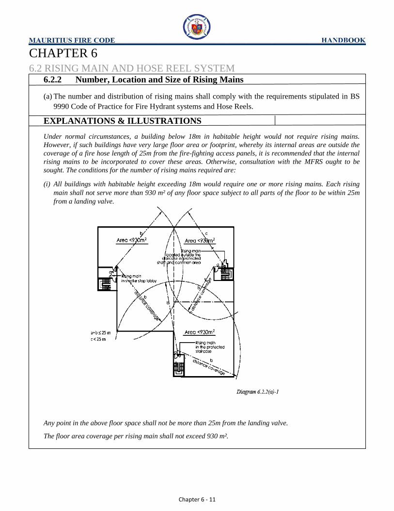
(i) All buildings with habitable height exceeding 18m would require one or more rising mains. Each rising
main shall not serve more than 930 m² of any floor space subject to all parts of the floor to be within 25m
from a landing valve.
Any point in the above floor space shall not be more than 25m from the landing valve. The floor area coverage per rising main shall not exceed 930 m².

Chapter 6 - 12
EXPLANATIONS & ILLUSTRATIONS 6.2.2(a)
Diagram 6.2.2(a)-2
The provision of rising main shall be such that all parts of any floor are within 25m from a landing valve,
measured along a route suitable for hose lines including any distance up or down a staircase.

Chapter 6 - 13
(b) Position of rising mains and the associated landing valves shall be kept free of obstruction both
physically and visually and located:
(i) within fire-fighting lobby, smoke-stop lobby or external corridor immediately outside the
door of the exit staircase; (ii) In the case where there are no fire-fighting lobby, smoke-stop lobby or external corridor, it
shall be located inside exit staircase, or in the common area and within a protected shaft,
immediately outside the door of the exit staircase.
Note: Where there are provisions of fire -fighting lobby or smoke-stop lobby within the building, the
position of rising mains and landing valves shall first be located inside fire-fighting lobby.
EXPLANATIONS & ILLUSTRATIONS 6.2.2
Siting of rising mains
(i) Rising main in fire fighting lobby or smoke stop lobby
Fire-fighting lobby or Smoke stop lobby
Diagram 6.2.2(b) (i)-1

Chapter 6 - 14
EXPLANATIONS & ILLUSTRATIONS 6.2.2(b)
Diagram 6.2.2(b)(i)-2
Diagram 6.2.2(b) (i)-3

Chapter 6 - 15
EXPLANATIONS & ILLUSTRATIONS 6.2.2(b)
Diagram 6.2.2(b)(i)-4
In the above situation (Diagram 6.2.2(b)(i) – 4) where the rising mains are located outside the staircases and
along external exit passageway/external corridor which are naturally ventilated, there is no need to protect the
rising main and landing valve separately, because the external exit passageway/external corridor is treated as
‘protected lobby’, for the purpose of interpretation and application of this requirement.
Chapter 6 - 16
EXPLANATIONS & ILLUSTRATIONS 6.2.2(b)
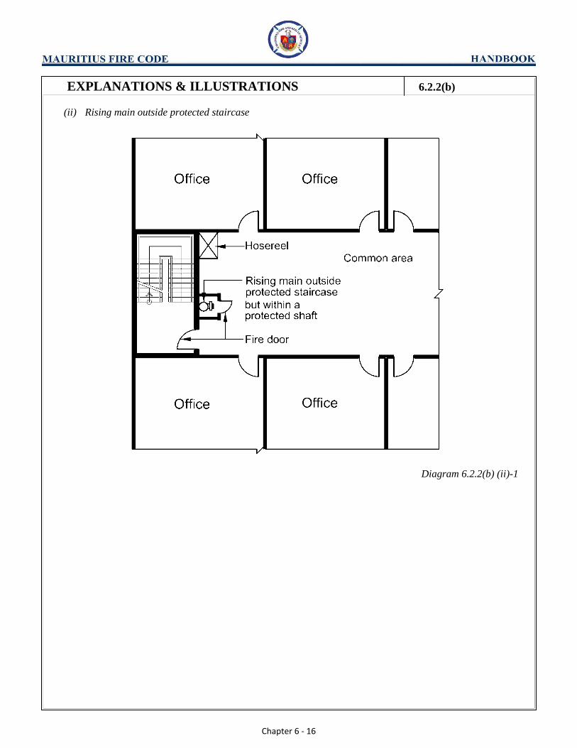
(ii) Rising main outside protected staircase
Diagram 6.2.2(b) (ii)-1

Chapter 6 - 17
EXPLANATIONS & ILLUSTRATIONS 6.2.2(b)
(iii) Rising main inside protected staircase
Diagram 6.2.2(b) (ii)-2
The location of the rising main should not cause obstruction to the escape path inside the staircase.
(iv) Rising mains situated at various positions within same building
Diagram 6.2.2(b) (I) & (ii)
As rising mains provide the ready water supply to fire fighters in the building, the main and its landing valve
should be protected from fire or mechanical damage.

Chapter 6 - 18
(c) Size of rising mains shall comply with BS 9990.
EXPLANATIONS & ILLUSTRATIONS 6.2.2
(i) Size of rising mains. The minimum nominal bore of a rising main shall be:
(a) 100mm where the rising main does not exceed 45m in height and only one landing valve is provided at
each floor.
Diagram 6.2.2(c) (i) (a) 100mm minimum nominal bore

Chapter 6 - 19
EXPLANATIONS & ILLUSTRATIONS 6.2.2(c)
(b) 150mm where the rising main either (I) exceeds 45m in height or (ii) is permitted to have two landing
valves on any floor.
Diagram 6.2.2(c) (i) (b) 150mm min. nominal bore rising main
The height of rising main is the habitable height measured from the fire engine access level to the finished
floor level of the topmost floor served by the rising main, irrespective whether or not the main is extended
above roof level. The above diagram shows two landing valves being installed in the top 2 floors though the
height of rising main does not exceed 45m, the minimum nominal bore of the rising main shall not be less than
150mm. See cl.2.4.12.2 of BS 9990 which allows that where “one rising main is permitted for a floor area
exceeding 930m², two landing valves shall be provided per floor, in which case the nominal bore of the rising
main shall be 150mm”. However, this requirement shall be not be applicable to any floor exceed 1400m².
Chapter 6 - 20
(d) Location and provision for landing valves shall comply with BS 9990.
(i) Landing valve is not required to be provided at the 1st
storey level to buildings under
Purpose Group II if the breeching inlets are installed in accordance with clause 6.2.3(c). (ii) Where all the exit staircases in a building under Purpose Groups III to VIII are installed with
rising mains and standby fire hoses, and yet part of a floor space is beyond the 25m
coverage of any landing valve, an additional standby fire hose shall be provided at the
landing valve nearest to this floor space.
EXPLANATIONS & ILLUSTRATIONS 6.2.2
(i) Location of rising mains
The entire pipework and landing valves comprising each rising main system inside the building shall be
confined:
(a) within a ventilated lobby of a protected lobby approach stairway, where this is provided, or (b) in such other protected areas as may be agreed with the MFRS.
(ii) Rising mains shall be so located that they are protected against mechanical and fire damage. (iii) No part of a rising main shall be placed in any shaft containing a gas, steam or fuel pipelines or
electrical cables and wirings. (iv) Where passing through other than protected area e.g. protected lobby shaft, pipe need to be encased or
protected by and fire rating material with 2-hour fire resistance rating.
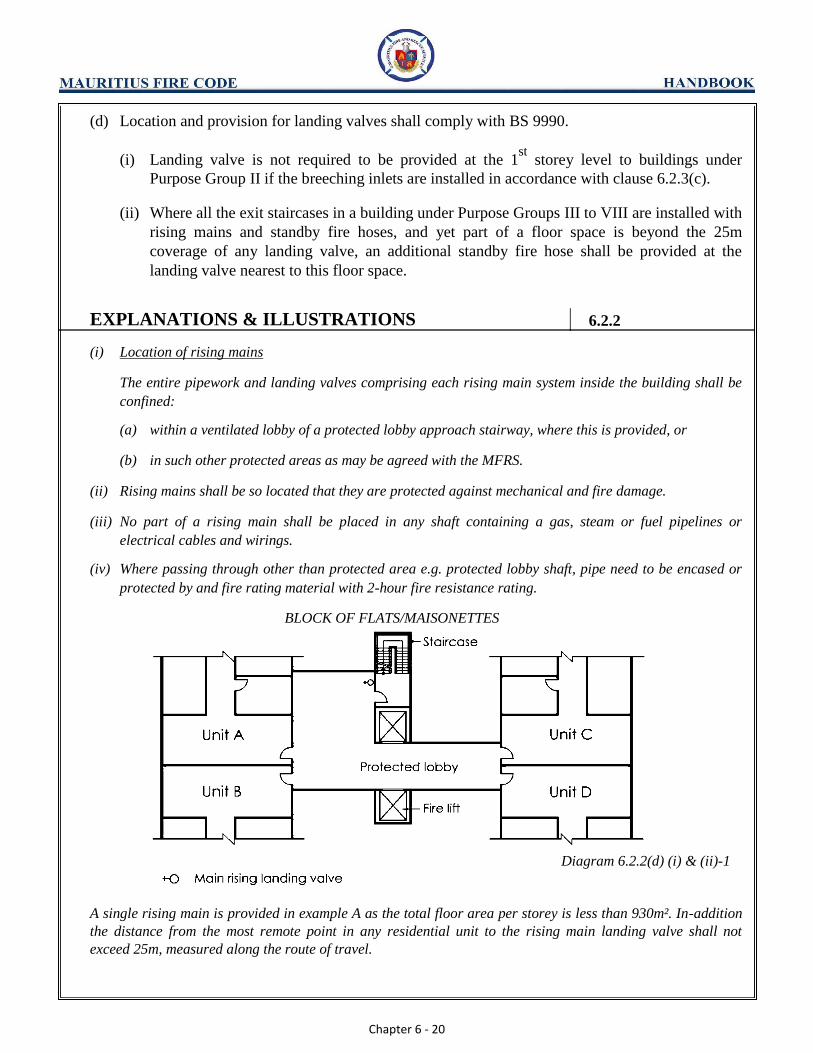
BLOCK OF FLATS/MAISONETTES
Diagram 6.2.2(d) (i) & (ii)-1
A single rising main is provided in example A as the total floor area per storey is less than 930m². In-addition
the distance from the most remote point in any residential unit to the rising main landing valve shall not
exceed 25m, measured along the route of travel.
Chapter 6 - 21
EXPLANATIONS & ILLUSTRATIONS 6.2.2(d)
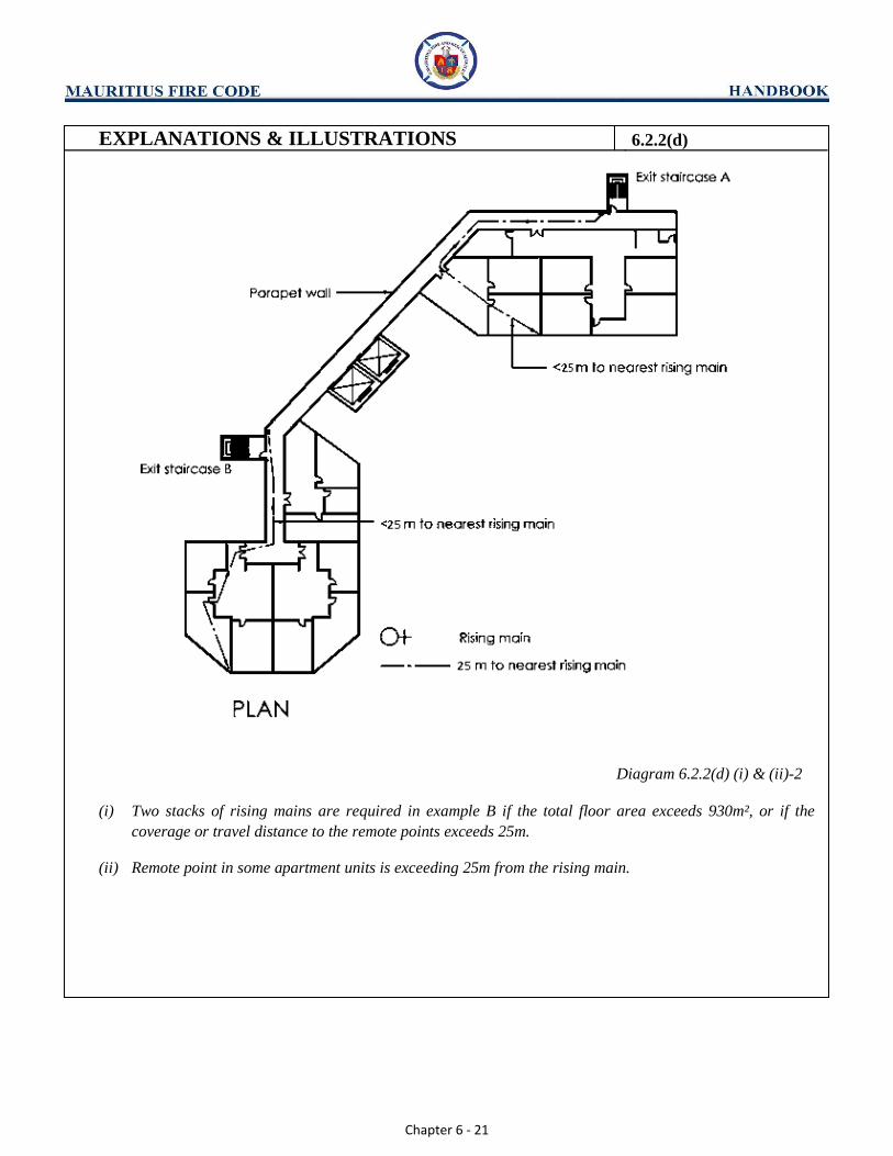
Diagram 6.2.2(d) (i) & (ii)-2
(i) Two stacks of rising mains are required in example B if the total floor area exceeds 930m², or if the
coverage or travel distance to the remote points exceeds 25m.
(ii) Remote point in some apartment units is exceeding 25m from the rising main.

Chapter 6 - 22
EXPLANATIONS & ILLUSTRATIONS 6.2.2(d)
Office/Factory/Warehouse block
A single rising main is provided in the above diagram as the total floor area per storey is less than 930m². In-
addition the distance from the most remote point in any unit to the rising main landing valve shall not exceed
25m, measured along the route of travel.
Chapter 6 - 23
EXPLANATIONS & ILLUSTRATIONS 6.2.2(d)
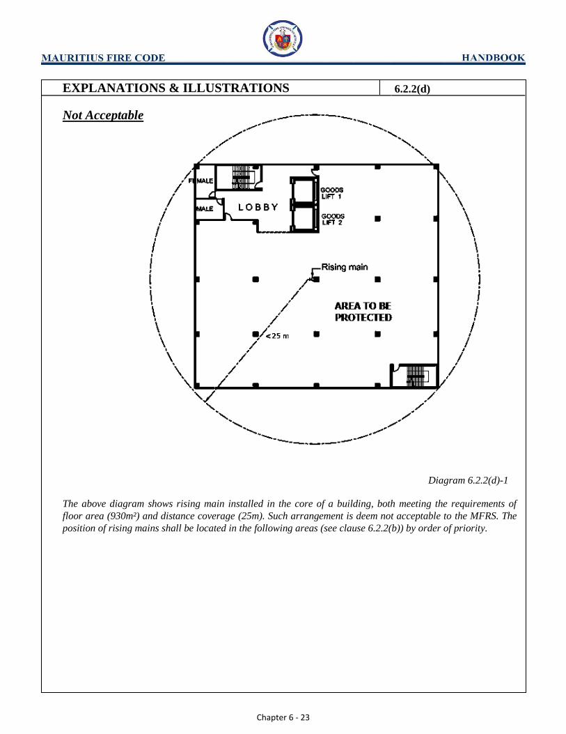
Not Acceptable
Diagram 6.2.2(d)-1
The above diagram shows rising main installed in the core of a building, both meeting the requirements of
floor area (930m²) and distance coverage (25m). Such arrangement is deem not acceptable to the MFRS. The
position of rising mains shall be located in the following areas (see clause 6.2.2(b)) by order of priority.

Chapter 6 - 24
EXPLANATIONS & ILLUSTRATIONS 6.2.2(d)
Acceptable
Diagram 6.2.2(d)-2
The above diagram is an acceptable arrangement of positioning rising mains in the order of priority. Two
stacks of rising main are required if the floor area exceeds 930m² and the distance exceeds 25m distance
measured from the landing valve to the remote points.
AREA TO BE PROTECTED
<25m
<25m
<25m
Chapter 6 - 25
EXPLANATIONS & ILLUSTRATIONS 6.2.2(d)
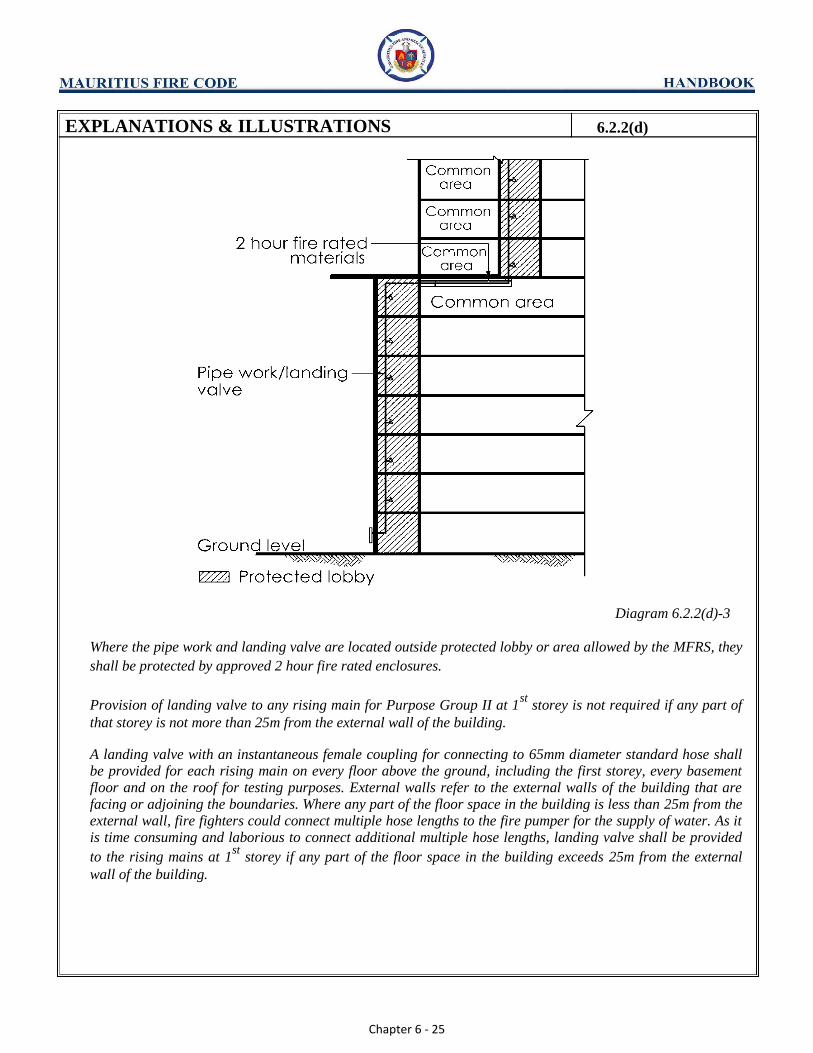
Diagram 6.2.2(d)-3
Where the pipe work and landing valve are located outside protected lobby or area allowed by the MFRS, they
shall be protected by approved 2 hour fire rated enclosures.
Provision of landing valve to any rising main for Purpose Group II at 1st
storey is not required if any part of
that storey is not more than 25m from the external wall of the building.
A landing valve with an instantaneous female coupling for connecting to 65mm diameter standard hose shall be provided for each rising main on every floor above the ground, including the first storey, every basement floor and on the roof for testing purposes. External walls refer to the external walls of the building that are facing or adjoining the boundaries. Where any part of the floor space in the building is less than 25m from the external wall, fire fighters could connect multiple hose lengths to the fire pumper for the supply of water. As it is time consuming and laborious to connect additional multiple hose lengths, landing valve shall be provided
to the rising mains at 1st
storey if any part of the floor space in the building exceeds 25m from the external
wall of the building.

Chapter 6 - 26
(e) Installation of rising main shall comply with BS 9990.
EXPLANATIONS & ILLUSTRATIONS 6.2.2 (e)
No illustration.

Chapter 6 - 27
CHAPTER 6
6.2 RISING MAIN AND HOSE REEL SYSTEMS
6.2.3 Breeching inlets and Access ways
(a) All buildings fitted with rising mains shall have access ways or fire engine access road (only
applicable to buildings under Purpose Group II) for pumping appliances within 18m of the
breeching inlet. The breeching inlets shall be visible from the access ways or fire engine access
road.
EXPLANATIONS & ILLUSTRATIONS
Distance between breeching inlets and pumping appliances
Diagram 6.2.3(a)
(i) The breeching inlets would be located on the external wall of the building and to be within 18m of the fire
engine access way or fire engine access road (only applicable for buildings under Purpose Group II). The
breeching inlets shall be visible from the adjacent access way.
(ii) Thus, an access way may serve more than one rising main to one or more buildings, provided (i) above is
complied with.
18m

Chapter 6 - 28
(b) Requirements and provisions for breeching inlets for the rising main system shall be in
accordance with the BS 9990 Code of Practice for Fire Hydrant systems and Hose Reels.
Connecting pipe between the inlets and the vertical run of the rising main, where applicable,
shall be kept as short as possible.
EXPLANATIONS & ILLUSTRATIONS 6.2.3
No illustration.
The inlets and the vertical run of the rising main shall be kept as short as possible. The total pressure loss of
the dry rising main shall not exceed 6 bar based on the design water flow rate. This is to correspond with the
maximum habitable height of 60m.
Chapter 6 - 29
CHAPTER 6
6.2 RISING MAIN AND HOSE REEL SYSTEMS
6.2.4 Wet Rising Main
(a) Capacity of the water supply from the public mains and the storage capacity for a wet rising
main system shall comply with the requirements in BS 9990 Code of Practice for Fire Hydrant
systems and Hose Reels.
EXPLANATIONS & ILLUSTRATIONS
No illustration.
(1) For wet rising mains it is essential that pressures and flows be adequate at all times to serve the required
number of jets likely to be used. (2) The water supply to the rising mains should be kept entirely independent of water supplies feeding other
installations including those for other fire fighting systems. (3) Means of supply for wet rising mains
(i) Each wet rising main shall be fed from a suction or storage tank having a minimum effective storage
capacity capable of supplying water at the rate of 27 l/s for a period of at least 30 minutes.
(ii) The storage tank(s) shall be automatically supplied either directly or indirectly via other tanks from a
public main(s). The pipe drawing water from public mains to the tank shall be at least 150mm in
diameter.
(iii) Break tanks not serving as storage tanks shall have an effective holding capacity of not less than
11.5m³ for each wet rising main.
(4) Water tanks for wet rising mains
Tanks supplying water for domestic purposes shall not be used as suction tanks for wet rising mains.

Chapter 6 - 30
(b) Flow
Flow requirements for wet rising main system shall comply with those stipulated in BS 9990.
EXPLANATIONS & ILLUSTRATIONS 6.2.4
No illustration.
(1) The minimum water supply flow rate shall be maintained in the wet rising system when 3 landing valves
within the system are in the fully open position:
(a) 27l/s for a residential bldg.
(b) 38 l/s for a non-residential and mixed occupancy bldg.
(2) When more than one wet rising main is required in any zone in a building, the minimum common water
supply shall be as stated below. Where the total maximum supply rate exceeds those stated in (a) and (b),
another common water supply system shall be used.
(a) For a residential building, 27 l/s for the first rising main and 13.5 l/s for each additional rising main,
subject to a total maximum supply rate of 135 l/s. (b) For a non-residential or any mixed occupancy building 38 l/s for the first rising main and 19 l/s for
each additional rising main, subject to a total maximum supply rate of 190 l/s.

Chapter 6 - 31
(c) Running pressure
Running pressure at each discharging landing valve on the wet rising main system shall be
maintained between the minimum and maximum values as stipulated in BS 9990.
EXPLANATIONS & ILLUSTRATIONS 6.2.4
No illustration.
A minimum running pressure of 3.5 bar and a maximum of 5.5 bar shall be maintained at each landing
valve when any number, up to three, are fully opened.

Chapter 6 - 32
(d) Static pressure
Static pressure in any line of hose connected to a landing valve in a wet rising main system shall
not exceed the specified value in BS 9990.
EXPLANATIONS & ILLUSTRATIONS 6.2.4
No illustration.
(i) To reduce the risk of hose bursting, arrangements shall be made in accordance with BS 5041: Pt 1 so that
when the water is shut off at the nozzle the static pressure in any line of hose connected to a landing valve
does not exceed 8 bars.
(ii) To dispose of excess flows and pressures over and above those required (i.e. when only one jet is in use) a
pressure control valve shall be incorporated in the body of the landing valve which is then permanently
connected into the relief pipe. This relief pipe should run throughout the length of the wet rising main
installation and should terminate either back into the suction tank or to drain.
Chapter 6 - 33
(e) The location of storage tank and capacity of break tank where required shall comply with the
requirements in BS 9990.
EXPLANATIONS & ILLUSTRATIONS 6.2.4
(For illustration see diagram 6.2.4(e) - 1)
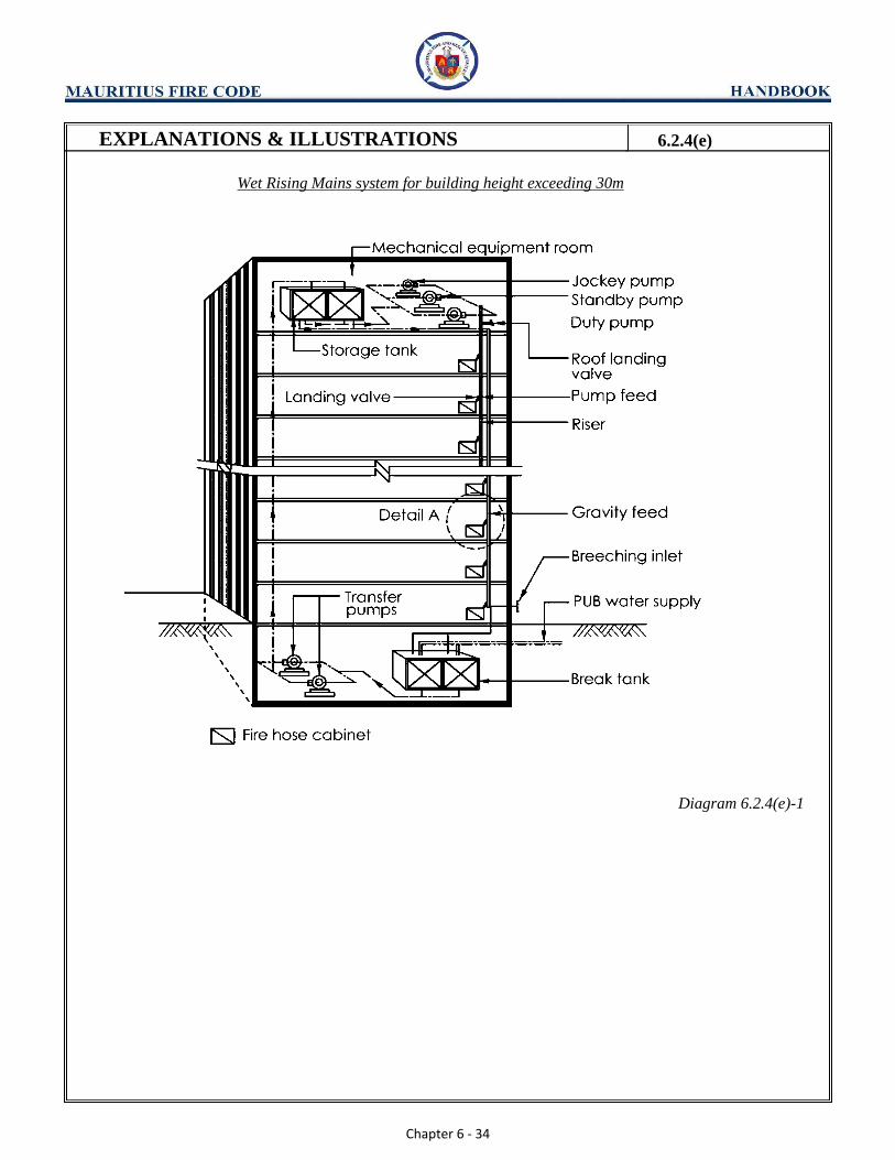
(1) The location and number of storage tank would be determined by the design of the wet rising main system
and the height of the building. BS 9990 should be fully complied with.
(2) It is important that at early design stage of the building, the type of design of the wet rising main system
should be drawn up to allow allocation of space for pumps and water tanks.
(3) Usually, storage tanks and pumps are located in mechanical service floor in upper storey and basement,
and on the roof of the building.
(4) The capacity of break tank shall have an effective holding capacity of not less than 11.5m³ for each wet
rising main.
Footnote:
(1) Storage tank is water tank having a minimum effective wet rising main storage capacity capable of
supplying water at a given rate for a period of at least 30 minutes.
(2) Break tank is either (a) a tank into which the incoming supply connection from the CWA water mains
discharge, or (b) an intermediate tank for limiting the system pressure.
(3) Suction tank is a tank from which a pump can draw water.
Chapter 6 - 34
EXPLANATIONS & ILLUSTRATIONS 6.2.4(e)
Wet Rising Mains system for building height exceeding 30m
Diagram 6.2.4(e)-1

Chapter 6 - 35
EXPLANATIONS & ILLUSTRATIONS 6.2.4(e)
Diagram 6.2.4(e)-2
Wet rising mains system
(1) “Wet rising mains” function similarly to dry rising mains. However, the pipes are permanently charged
with water from a pressurised supply, and fitted with landing valves on various floors. (2) The breeching inlet act as an alternative means of supplying water to the rising mains system should the
incoming public water supply pipes be damaged or the water supply is inadequate.
Chapter 6 - 36
(f) Installation of fire pumps for wet rising main system shall comply with requirements of BS 9990.
Wet riser pumps shall be installed within a fire compartmented fire pump room, whose fire rating
shall be in accordance with Table 6.4A. The fire pump room floor level shall not be lower than
the main floor level.
EXPLANATIONS & ILLUSTRATIONS 6.2.4
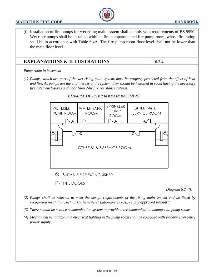
Pump room in basement
(1) Pumps, which are part of the wet rising main system, must be properly protected from the effect of heat
and fire. As pumps are the vital nerves of the system, they should be installed in room having the necessary
fire rated enclosures and door (min 2-hr fire resistance rating).
EXAMPLE OF PUMP ROOM IN BASEMENT
Diagram 6.2.4(f)
(2) Pumps shall be selected to meet the design requirements of the rising main system and be listed by
recognised institution such as Underwriters’ Laboratories (UL) or any approved standard. (3) There should be a voice communication system to provide intercommunication amongst all pump rooms. (4) Mechanical ventilation and electrical lighting in the pump room shall be equipped with standby emergency
power supply.

Chapter 6 - 37
CHAPTER 6
6.2 RISING MAIN AND HOSE REEL SYSTEM
6.2.5 Standby Fire Hose For Rising Main
(a) Standby fire hose shall be provided for every rising main. The following requirements shall be
complied with:
Type and Folding Method
(i) The standby fire hose shall be of 65mm nominal internal diameter in order to ensure that the
hose coupling will fit existing coupling tail pieces. The hose shall be rugged and capable of
carrying water under substantive pressure in accordance with BS 6391. The fire hose shall
be Type 3 as stipulated in the BS 6391. (ii) The fire hose couplings shall be manufactured to BS specification or equivalent and of light
alloy or gunmetal. The coupling shall be of type 65mm and be of the instantaneous type
with standard (double-pull) release mechanism. The couplings shall be tied in by binding
with galvanized mild steel wire and applied over a hose guard of synthetic fibre. It shall be
able to withstand a minimum working pressure of 15 bars. (iii) Each hose shall have a standard length of 25m and shall be kept stowed in a Dutch Rolled
position and housed in a glass fronted cabinet. The Dutch Roll shall be rolled in the manner
shown in Diagram 6.2.5(a).

Chapter 6 - 38
EXPLANATIONS & ILLUSTRATIONS 6.2.5(a)
Standby hose provides the fire fighter greater hose length connection in situation where the floor space is extensive.
The hose from other floors could be transferred to fire floor quickly when required by fire fighters. Standby hose
shall be kept locked in a cabinet, when placed along escape corridor, in common area and circulation space. The
hose is allowed to be left mounted on hook or cradle inside the riser main shaft.
Diagram 6.2.5(a)

Chapter 6 - 39
(b) Position
(i) The fire hose shall be installed just next to, but not more than 2m from the landing valve as
shown in Diagram 6.2.5(b).
(ii) The entire fire hose and cabinet shall be out of direct sunlight.
EXPLANATIONS & ILLUSTRATIONS 6.2.5
Diagram 6.2.5(b)

Chapter 6 - 40
(c) Mounting
The wall mounted fire hose and cabinet shall be as follows:
(i) The cabinet shall be firmly mounted on the wall and rigid to take either one or two fire
hose weight. (ii) The cabinet shall be constructed of non-combustible material and maintenance free.
(iii) The cabinet lock, if provided, shall be one of the type that could be operated manually from
the inside without the use of a key when the front plain glass/plastic (minimum 300mm x
300mm) is broken by the fire-fighter. (iv) The cabinet swing door shall be made openable such that it will not obstruct the retrieving
of the fire hose by the fire-fighter. (v) The depth of the cabinet shall not exceed 250mm for one fire hose or 350mm for two fire
hoses. (vi) The cabinet shall be painted in a contrasting colour such that it is conspicuous and easily
identified. (vii) The wording, “FIRE HOSE”, with letter height of at least 50mm and shown in contrasting
colour, shall be painted directly on the front panel as shown in Diagram 6.2.5(b). (viii) In lieu of the cabinet, simple wall mounted cradle for the fire hose can be provided, but
only in the riser main shaft. The cradle shall be constructed and positioned to facilitate the
retrieving of fire hose by the fire-fighter. (ix) The cradle (in lieu of the cabinet) shall be maintenance free. The fire hose installation
height shall be limited as indicated in Diagram 6.2.5(b).
EXPLANATIONS & ILLUSTRATIONS 6.2.5
No illustration.

Chapter 6 - 41
(d) General
(i) Only clean, dry and compact rolled (Rolled from female coupling) and hose shall be placed
in the cabinet.
(ii) BS 6391 stipulates the technical requirements for quality acceptance standards of the fire
hose. In addition, the abovementioned requirements shall be applicable for acceptance of the
standby fire hose.
EXPLANATIONS & ILLUSTRATIONS 6.2.5
No illustration.

Chapter 6 - 42
CHAPTER 6
6.2 RISING MAIN AND HOSE REEL SYSTEMS
6.2.6 Building under construction
When a building in pursuance of Cl.6.2.1, is required to be equipped with rising mains, such rising
mains shall be installed progressively as the building attains height during the course of construction.
All outlets, landing valves and inlets, water tanks and pumps, and hydrants as may be required for the
system, shall be properly installed as directed by the MFRS so as to be readily operational in case of
fire. Please see Appendix (3) on fire safety requirements for buildings under construction.
EXPLANATIONS & ILLUSTRATIONS
Building under construction
Provision of wet rising main is required when building exceeds a habitable height of 30m
Diagram 6.2.6-1
<30M

Chapter 6 - 43
EXPLANATIONS & ILLUSTRATIONS 6.2.6
Rising main is dry type before the habitable height of 30m is reached
Diagram 6.2.6-2
Rising main is converted to wet type with the installation of pump and water tank
(a) Breeching inlets Breeching inlets (2-way or 4-way) should be provided as per approved building plan.
(b) Fire lift
As it is not feasible to provide fire lift for use by fire fighters, a passenger hoist, which is usually
installed at site could be used. The hoist need not serve the topmost 3 floors, until the roof is being
completed. (c) Electrical power supply
Supply from power grid or generator set could be acceptable.
>30M
Chapter 6 - 44
EXPLANATIONS & ILLUSTRATIONS 6.2.6
(d) Fire engine access road
During construction stage, there could be other works involving laying of services, excavation work etc.
that would prevent provision of access road and the space available would not permit the manoeuvrability
of fire engine.
However, every opportunity should be taken to put in the access road in place. This is necessary for the
purpose of conducting effective firefighting operations should a fire occur at any time. In view of the
above, additional portable fire extinguishers should be provided at each floor level instead.
(e) Rising main landing valve
Rising main and landing valve shall be provided to every floor, except the topmost 3 floors as the building
gains height, and made operational. (f) Rising main pressure & flow
As it is not feasible to provide a full-sized water tank and pump to meet the flow and pressure required for
45mins of firefighting, a break tank of minimum 11.5m³ should be provided, instead for firefighting of
5mins duration. Upon the arrival of fire engine the tank could be replenished via the public hydrant. The
break tank must be constructed before the building reaches the 30m height.
(g) Responsibility/Accountability
The main contractor for the project shall be responsible and accountable for the provision and
maintenance of the rising main in the building under construction.

Chapter 6 - 45
EXPLANATIONS & ILLUSTRATIONS 6.2.6
(h) Checklist
Inspection and testing checklists of rising mains are attached for ease of reference.
INSPECTION CHECKLIST FOR BUILDING UNDER CONSTRUCTION
S/No Description Yes If no, remedy
action / comment
PART A
1 Dry rising mains shall be installed progressively
during the course of construction as per approved plan
and made operational for all storeys except the
uppermost 3 storeys, for building exceeding 18m.
2 Wet rising mains shall be installed progressively
during the course of construction as per approved plan
and made operational for all storeys except the
uppermost 3 storeys, for building exceeding 30m.
The following shall be provided:
a. Break tank with minimum water capacity of 11.5
cubic metre; and
b. Fire pumps which are operational and supplied
with emergency power supply.
3 Provision of breeching inlets. (2-way / 4-
way)*provided as per approved plan. The following
shall be complied with:
a. Breeching inlets made operational and housed in
protective enclosure; and
b. Labelled and numbered accordingly.
4 Riser stacks labelled and numbered accordingly:
a. Earthing to be provided; and
b. Air relief valve provided.
5 Landing valves provided with blank caps and are
strapped and padlocked (with key box holding
appropriate key) in closed position.
6 Dry rising mains are hydrostatically tested to constant
pressure of 13.8 bars for at least 2 hours.
Date inspected: ____________by______________________Signature_____________
*Delete as appropriate

Chapter 6 - 46
EXPLANATIONS & ILLUSTRATIONS 6.2.6
S/No Description Yes If no, remedy
action/comments
PART B : CHECKLIST FOR THE TESTING OF RISING MAINS
BREECHING INLET
In -Order
Not In -
Order Remarks
1 Inlet housed in protective enclosure
2 Rigidly Support
3 Labelled “dry/ Wet Riser” and numbered
accordingly
4 Clear of obstruction
RISER
5
Air relief valve provided
6
Labelled & numbered accordingly
7
Earthing provided
LANDING VALVE
8 Blank Cap provided
9
Strapped and padlock in closed position
10
Clear of obstruction
TESTING OF PRESSURE/FLOW
11
Dry rising mains
a. Pressure constant at 300
psi (20.7 bar) for 30 mins.
b. Regularly tested
12
Wet rising mains
a. Static pressure shall not be less
than 8 bar
b. Topmost landing valve
Fully opened (under
pump/gravity feed) with flow
rate at 27 L/S
c. Provide break tank with Minimum water
capacity of 11.5 m
Date inspected: by: Signature:
*Delete as appropriate
Chapter 6 - 47
CHAPTER 6
6.2 RISING MAIN AND HOSE REEL SYSTEMS
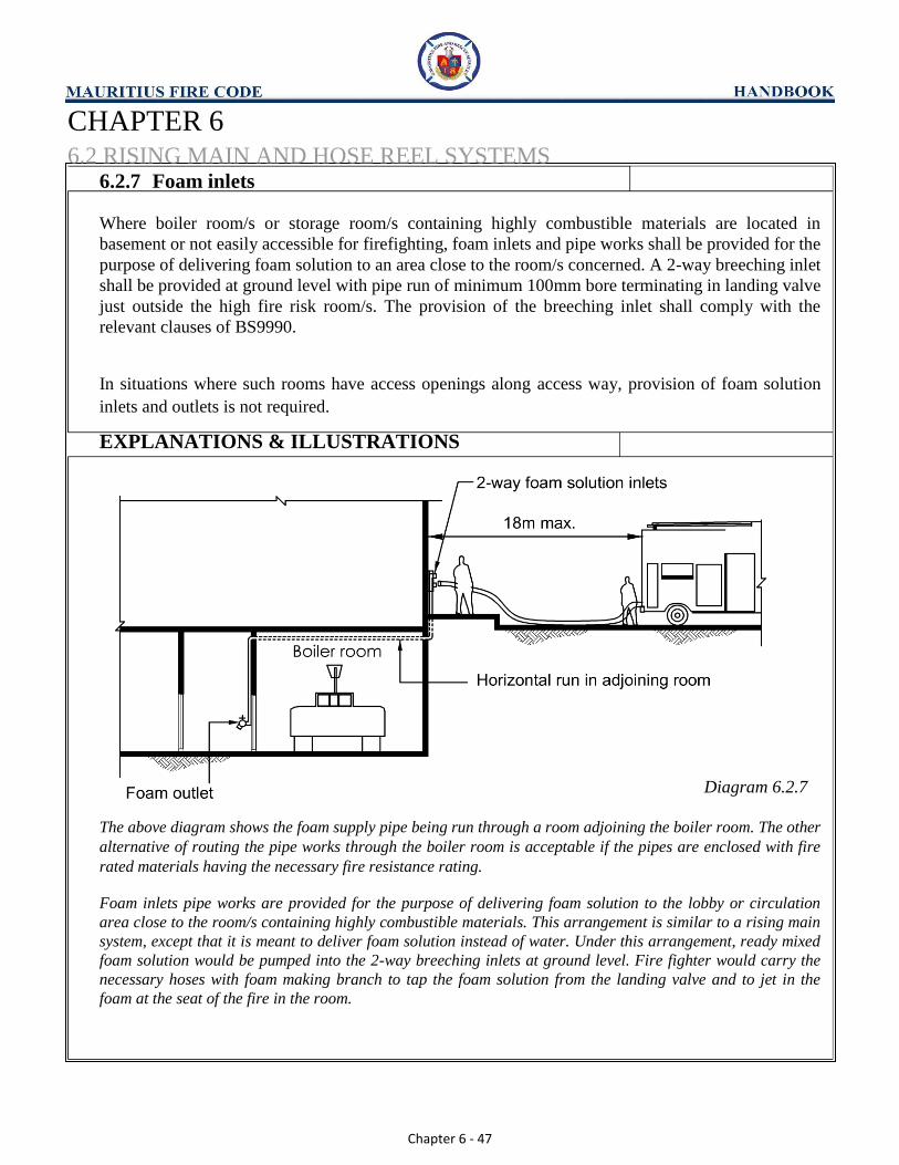
6.2.7 Foam inlets
Where boiler room/s or storage room/s containing highly combustible materials are located in
basement or not easily accessible for firefighting, foam inlets and pipe works shall be provided for the
purpose of delivering foam solution to an area close to the room/s concerned. A 2-way breeching inlet
shall be provided at ground level with pipe run of minimum 100mm bore terminating in landing valve
just outside the high fire risk room/s. The provision of the breeching inlet shall comply with the
relevant clauses of BS9990.
In situations where such rooms have access openings along access way, provision of foam solution
inlets and outlets is not required.
EXPLANATIONS & ILLUSTRATIONS
Diagram 6.2.7
The above diagram shows the foam supply pipe being run through a room adjoining the boiler room. The other
alternative of routing the pipe works through the boiler room is acceptable if the pipes are enclosed with fire
rated materials having the necessary fire resistance rating.
Foam inlets pipe works are provided for the purpose of delivering foam solution to the lobby or circulation
area close to the room/s containing highly combustible materials. This arrangement is similar to a rising main
system, except that it is meant to deliver foam solution instead of water. Under this arrangement, ready mixed
foam solution would be pumped into the 2-way breeching inlets at ground level. Fire fighter would carry the
necessary hoses with foam making branch to tap the foam solution from the landing valve and to jet in the
foam at the seat of the fire in the room.

Chapter 6 - 48
CHAPTER 6
6.2 RISING MAIN AND HOSE REEL SYSTEM
6.2.8 Hose Reels
(a) Hydraulic hose reel conforming to the requirements in BS9990. Code of Practice for Fire
Hydrant Systems and Hose Reels shall be provided in every storey of every building regardless
of building height, except the following:
(i) Purpose Group I buildings; (ii) Non- residential occupancy at the 1st storey of a residential building, and fulfilling the
following conditions:
(1) Floor area of the shop or office unit does not exceed 150m²;
(2) Compartmented from the residential floors and other parts of the building;
(3) Not being used as an eating establishment, storage of flammable materials;
(4) Not being used as public entertainment outlet;
(5) Not belonging to Purpose Group VI & VIII.
(iii) Any other small stand-alone single-storey guardhouse, bin centre, electrical sub-station and
open-sided shed not exceeding 200m² (excluding those in Purpose Group VI & VIII).
(iv) Subject to compliance with Cl.2.6.2, provision of hose reel on the mezzanine floor of
factory unit is not required provided the coverage distance of the nearest hose reel at the
main floor to the most remote point of the mezzanine floor shall not exceed 36m.
EXPLANATIONS & ILLUSTRATIONS
Diagram 6.2.8(a)-ii
The staircase serving the upper storey living quarters shall be compartmented from the shop area by minimum 1-hour fire
rated enclosures. The communicating side access door between the staircase and shop area at 1st
storey level shall be
minimum ½-hour fire rated and fitted with self-closer. This door shall always be kept in the closed position to prevent smoke and fire from spreading to the living quarters if there is a fire in the shop area.

Chapter 6 - 49
EXPLANATIONS & ILLUSTRATIONS 6.2.8(a)
Small buildings refer to detached and standalone buildings, such as guardhouse, pump house, bin centre,
electrical substation. These would not be required to be provided with hydraulic hose reel. However, suitable
type of fire extinguisher should be provided instead. For other types of small building, Qualified Persons
should consult the MFRS before making building plan submission.
Diagram 6.2.8(a) (iv)
*Distance is to be measured along a route suitable for the hose line having regard to any obstruction.
Chapter 6 - 50
(b) Size and type
The hose shall be of 20mm or 25mm nominal diameter and conform to BS EN 694, not
exceeding 30m in length and terminating in ‘shut-off’ branches with 4mm or 6mm nozzles.
EXPLANATIONS & ILLUSTRATIONS 6.2.8
No illustration.
(1) The reel or drum should be of adequate size to wind up the 30m length hose.
(2) The length of the hose should not exceed 30m. The main reasons are:
(a) An occupant using the hose reel to fight an incipient fire need not traverse more than 30m.
Consideration must be given that the occupant needs to retrace his path to a safe exit if the incipient
fire could not be put out. Thus, the aggregate travel distance to and from the incipient fire should not
be excessive; (b) Longer than 30m hose would require a bigger reel which would create some difficulties in running out
the hose and that jamming of tubing could occur when in use. (3) An operating instruction notice plate should be provided next to the stop valve. The hose reel operating
instructions shall be:
“Turn on the inlet valve before running out the hose”
(4) All hose reels should be tested at least once a year. The test is to ensure that they are maintained in
working order and able produce a jet of water with a minimum of 6m throw. (5) Hose reels located in recesses or cabinets shall bear the appropriate sign in accordance with BS ISO
3864-1
(6) Hose reels are now required to be type tested by a recognised testing laboratory to meet the standard of
EN 671 – 1 or any approved standard.
Chapter 6 - 51
(c) Water supply
Water supply for hose reels in terms of flow rate and minimum running pressure shall comply
with the requirements in BS 9990.
EXPLANATIONS & ILLUSTRATIONS 6.2.8
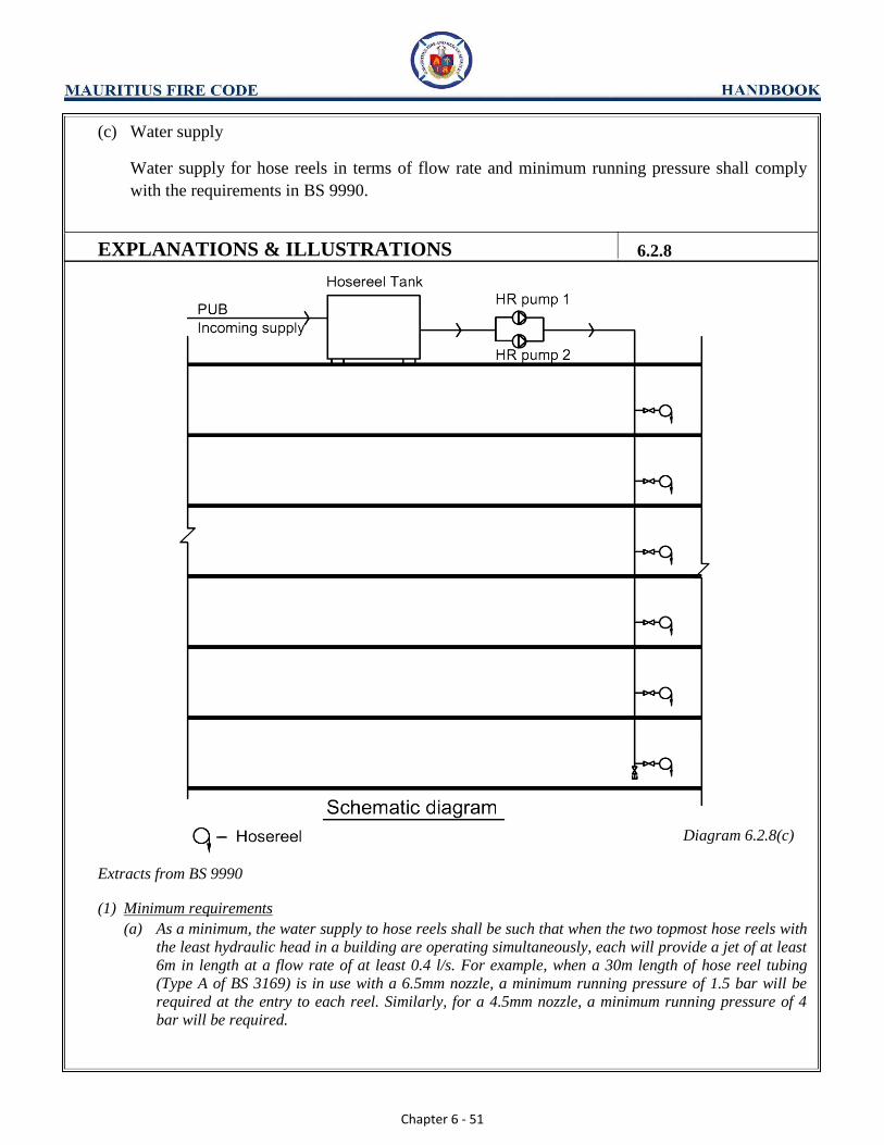
Diagram 6.2.8(c)
Extracts from BS 9990
(1) Minimum requirements (a) As a minimum, the water supply to hose reels shall be such that when the two topmost hose reels with
the least hydraulic head in a building are operating simultaneously, each will provide a jet of at least
6m in length at a flow rate of at least 0.4 l/s. For example, when a 30m length of hose reel tubing
(Type A of BS 3169) is in use with a 6.5mm nozzle, a minimum running pressure of 1.5 bar will be
required at the entry to each reel. Similarly, for a 4.5mm nozzle, a minimum running pressure of 4
bar will be required.

Chapter 6 - 52
EXPLANATIONS & ILLUSTRATIONS 6.2.8(c)
(b) Pipework shall not be less than 50mm nominal bore and feeds to individual hose reels shall be at least
25mm nominal bore.
(2) Hose reel pumps (a) Where the water pressure in hose reel main needs to be boosted, the provision of an electrically
driven pump is usually a convenient method. A duplicate standby pump shall also be provided. (b) Both motors and pumps shall be sited in positions where they are protected against tampering and
physical and fire damage and the electrical supply to them shall be by an exclusive circuit with the
cables following a route of negligible fire risk or be provided with adequate protection.
(c) The hose reel pumps system shall come into operation automatically with a drop in pressure or a flow
of water. Both pumps shall be automatically primed at all times.
(d) All pumps shall also be capable of being started or stopped manually. The standby pump shall be so
arranged that it will operate automatically on failure of the duty pump. Where more than one source
of electrical supply is available, the duty and standby pump shall be connected to the different
sources. (e) Connection for boosted supplies - pumps shall be fed from a suction tank or inter-connected tanks
having a minimum capacity of 1100 l. The tanks shall be automatically supplied from a town main or
a reliable source, controlled by a ball valve of minimum diameter 50mm. (f) Use of domestic water tank - tanks supplying water for domestic purposes shall not be used as
suctions for hose reel installations unless arrangements have been made for domestic supplies to be
drawn off in such a manner that the requisite reserve of water for the hose reel installation is always
preserved.
(3) Connection for boosted supplies.
Pumps shall be fed from a suction tank or inter-connected tanks having a min. capacity of 1100 l. The
tank(s) shall be automatically supplied from a town main or a reliable source, controlled by a ball valve
of minimum diameter 50mm.
(4) Use of Domestic Water Tanks. Tanks supplying water for domestic purposes shall not be used as suctions for hose reel installations
unless arrangements have been made for domestic supplies to be drawn off in such a manner that the
requisite reserve of water for the hose reel installation is always preserved. There shall not be any risk of
contamination of water due to stagnation in the tank.
Footnote: Hose reel and sprinkler systems can share the same water tank under the conditions stipulated in BS
EN 12845.

Chapter 6 - 53
(d) Siting & installation
Siting and details of installation for hose reels shall comply with the requirements in BS 9990.
EXPLANATIONS & ILLUSTRATIONS 6.2.8
Not Acceptable
Diagram 6.2.8(d)-1
The distribution of hydraulic hose reels as shown above is not acceptable as there is a pocket of area that is
beyond the coverage of the hose reels

Chapter 6 - 54
EXPLANATIONS & ILLUSTRATIONS 6.2.8(d)
Not Acceptable
Diagram 6.2.8(d)-2
Distribution of hydraulic hose reel
(1) Siting (a) Hose reels shall be sited in prominent and accessible positions adjacent to exits, preferably just outside
protected corridors, lobbies or staircases on exit routes, but not inside staircases.
(b) In planning the location of hose reels, consideration should be given to the following points:
(i) Access to hose reels should not be obstructed by the parking, loading and unloading of vehicles or
by the location of furniture, equipment or other material. (ii) Protection of hose reels from mechanical damage and unauthorised use
(iii) The location of internal walls, partitions, doorways, storage racking, stored heights of goods and
other obstructions, which could restrict normal hose coverage through the building. (2) Installation of hose reels
References shall be made to BS 9990 for details on installation of the hose reel
Chapter 6 - 55
(e) The use of copper or stainless steel piping is permissible for the connection of the hose reel to the
CWA mains.
EXPLANATIONS & ILLUSTRATIONS 6.2.8
No illustration.
(1) Pipework for hose reel system shall not be less than 50mm nominal bore and feeds to individual hose reels
shall be at least 25mm nominal bore. (2) Copper or stainless steel pipes may be incorporated in the pipe works supplying water to the hose reels.
The above sub-clause allows the flexibility of using alternative material for the water supply pipe of the hose
reel system.
Chapter 6 - 56
CHAPTER 6
6.2 RISING MAIN AND HOSE REEL SYSTEM
6.2.9 Graphical Symbol
Graphical symbols to depict fire safety equipment are allowed for use in buildings provided the signs
comply with BS ISO 3864. The Table below shows the different size of the graphical symbol with
respect to the viewing distance.
Table 6.2.9A
Viewing
Distance 0m to 6m >6m to 9m >9m to 12m 12m or more
Z=100 min. 60mm min. 90mm min. 120mm min. 150mm
Note: The luminous factor (Z) from BS 5266 is used to determine the size of the sign. It essentially
dictates the size of the sign that varies with distance. The graphical symbol for fire-fighting
equipment shall be sized such that the height and width are same. The size of symbol is not inclusive
of borders.
EXPLANATIONS & ILLUSTRATIONS
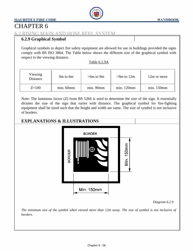
Diagram 6.2.9
The minimum size of the symbol when viewed more than 12m away. The size of symbol is not inclusive of
borders.

Chapter 6 - 57
CHAPTER 6
6.3 ELECTRICAL FIRE ALARM SYSTEM
6.3.1 General
(a) Every building or part of a building, except that of purpose group I or II (residential floors),
having a total floor area of more than that specified in Column B of Table 6.3A having regard to
the purpose group of the building or part of the building, shall be installed with a fire alarm
system, either of the automatic or manual type as indicated in Column C, which shall be an
electrically supervised system complying with the requirements of the BS 5839 and shall be
connected to a fire station through an approved alarm monitoring station if required under Cl
6.3.7.
EXPLANATIONS & ILLUSTRATIONS
Diagram 6.3.1(a)-1
Based on the floor area of 1st
storey, the above building is required to be provided with manual fire alarm
system to 1st
, 2nd
and 3rd
storey, which are for commercial usage. The bells of the alarm system shall be
extended to the common areas (lobbies, corridors, staircases, etc.) of the residential floor at 4th
storey.
Chapter 6 - 58
EXPLANATIONS & ILLUSTRATIONS 6.3.1(a)
Warehouse
Single storey warehouse not exceeding 2000m² is not required to be provided with fire alarm system unless
otherwise specified by the MFRS. The main reason is that the building is small; hence escape to the exterior
via exit doors would be straight- forward.
Warehouse building of 2 to 4 storeys and having a total floor area (per storey) of greater than 1000m² is
required to provide manual type of fire alarm system. This manual fire alarm system (break glass type) is not
required to be connected to an approved alarm monitoring station.
Warehouse building which is more than 4 storeys is required to be provided with automatic fire alarm system
such as smoke or heat detection types, irrespective of the floor area per storey.
Factory
Single storey factory building not exceeding 400m² is not required to be provided with fire alarm system unless
otherwise specified by the MFRS. The main reason is that the building is small; hence escape to the exterior
via exit doors would be straight- forward.
Factory building of 2 to 4 storeys and having a total floor area (per storey) of greater than 200m² is required
to be provided with manual type of fire alarm system. This manual fire alarm system (break glass type) is not
required to be connected to an approved alarm monitoring station.
Factory building which is more than 4 storeys is required to be provided with automatic fire alarm system
such as smoke or heat detection system, irrespective of the floor area per storey.
Chapter 6 - 59
EXPLANATIONS & ILLUSTRATIONS 6.3.1(a)
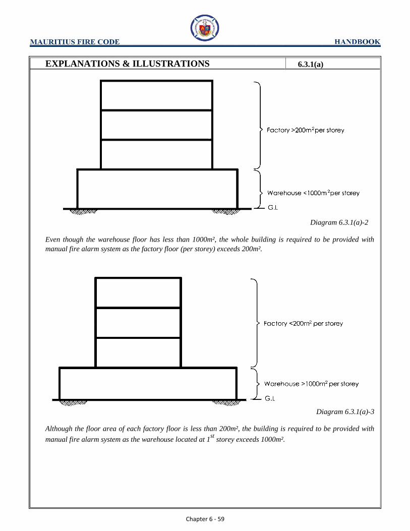
Diagram 6.3.1(a)-2
Even though the warehouse floor has less than 1000m², the whole building is required to be provided with
manual fire alarm system as the factory floor (per storey) exceeds 200m².
Diagram 6.3.1(a)-3
Although the floor area of each factory floor is less than 200m², the building is required to be provided with
manual fire alarm system as the warehouse located at 1st
storey exceeds 1000m².

Chapter 6 - 60
EXPLANATIONS & ILLUSTRATIONS 6.3.1(a)
Diagram 6.3.1(a)-4
Factory or Warehouse
As the factory floor area per storey is less than 200m² and the warehouse floor area is less than 1000m² there
is no need to provide fire alarm system unless requested by the MFRS. It should be noted that if in the event
that warehouse floor is granted change of use to factory, a manual fire alarm system will be required to be
provided to the whole building. The main reasons for the difference in floor area between factory and
warehouse are:
a) occupants load of factory is higher than warehouse;
b) occupants would be working for long hours in factory as compared to warehouse where workers would
only be involved when there is movement of goods in/out of the building.
Owners of factory or warehouse installed with manual fire system could opt for connection to the approved
alarm monitoring station. Approved alarm monitoring stations are private monitoring companies.

Chapter 6 - 61
EXPLANATIONS & ILLUSTRATIONS 6.3.1(a)
Office/ Shop
Single storey shop or office building not exceeding 400m2 is not required to be provided with fire alarm system
unless otherwise specified by MFRS. The main reason is that the buildings are small; hence escape to the
exterior via exit doors would be straight- forward.
Building of 2 to 4 storeys and having a total floor area (per storey) of greater than 200m2 is required to be
provided with manual type of fire alarm system. This manual fire alarm system (break glass type) is not
required to be connected to an approved alarm monitoring station.
Building which is more than 4 storeys is required to be provided with both automatic fire alarm system such as
smoke or heat detection system and manual fire alarm system, regardless of the floor area per storey.
Place of Public Resort
(i) With stay-in facilities:
Single storey building used as a place of public resort with stay-in facilities shall be provided with
manual type of fire alarm system, regardless of the floor area.
Building of 2 or more storeys shall be provided with both automatic fire alarm system such as smoke or heat
detector system and manual fire alarm system, regardless of the floor area per storey.
The main reason for having more stringent requirement in respect of the provision of fire alarm system is
the presence of sleeping risk involving guests.
(ii) Without stay-in facilities:
Single storey building used as a place of public resort without stay-in facilities and having a floor area
not greater than 400m2 is not required to be provided with fire alarm system unless otherwise specified
by the MFRS. The main reason is that the building is small, hence escape to the exterior via exit doors would be straight-forward.
Building of 2 to 4 storeys and having a total floor area (per storey) of greater than 200m2 shall be provided
with manual fire alarm system. This alarm system is not required to be connected to an approved alarm
monitoring station. Building which is more than 4 storeys is required to be provided with both automatic fire
alarm system such as smoke or heat detection system and manual fire alarm system, regardless of the floor
area per storey. This is in compliance with column C of Table 6.3A. The complementary manual fire alarm
system would allow occupants to activate the system before the automatic smoke or heat detection system is
set-off by the smoke or heat from the fire.
Note: Any reference to “a” under column c (Type of fire alarm) of Table 6.3A means both automatic &
manual fire alarm systems.
Mixed Occupancy
When there are two or more purpose groups in a building, the strictest requirement for any one of the purpose
groups shall be applicable to the whole building.
Chapter 6 - 62
EXPLANATIONS & ILLUSTRATIONS 6.3.1(a)
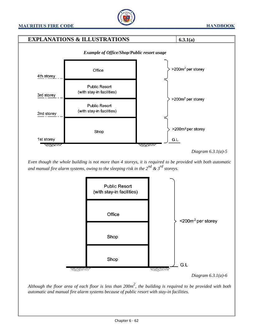
Example of Office/Shop/Public resort usage
Diagram 6.3.1(a)-5
Even though the whole building is not more than 4 storeys, it is required to be provided with both automatic
and manual fire alarm systems, owing to the sleeping risk in the 2nd
& 3rd
storeys.
Diagram 6.3.1(a)-6
Although the floor area of each floor is less than 200m2, the building is required to be provided with both
automatic and manual fire alarm systems because of public resort with stay-in facilities.

Chapter 6 - 63
EXPLANATIONS & ILLUSTRATIONS 6.3.1(a)
Diagram 6.3.1(a)-7
As the area per storey is less than 200m2 and the public resort does not have stay-in facilities, there is no need
to provide fire alarm system unless otherwise required by the MFRS.
Chapter 6 - 64
EXPLANATIONS & ILLUSTRATIONS 6.3.1(a)
School (i) Single storey school building is not required to be provided with fire alarm system unless otherwise specified
by the MFS. The main reason is that the building is single storey without sleeping accommodation; hence
escape to the exterior via exit doors would be straight- forward. (ii) Building of 2 to 4 storeys without sleeping accommodation and having a total floor area (per storey) of greater
than 400m2 is required to be provided with automatic type of fire alarm system. This automatic fire alarm
system is not required to be connected to an approved alarm monitoring station. If the total floor area per storey exceeds 4000m², then both automatic and manual fire alarm system are required to be provided under cl.6.3.1(c)
(iii) Building of 2 to 4 storeys with sleeping accommodation shall be provided with both automatic and manual fire
alarm system. (iv) Building which are more than 4 storeys but less than 24m in habitable height without sleeping accommodation
shall be provided with automatic type fire alarm system. If the total floor area per storey exceeds 4000m², then
both automatic and manual fire alarm system shall be provided under cl.6.3.1(c). (v) Building which are more than 4 storeys but less than 24m in habitable height with sleeping accommodation
shall be provided with both automatic and manual fire alarm system. Health care occupancy (i) With stay-in facilities:
Single storey building used as health care occupancy e.g. hospital, old folk home etc., with stay-in facilities
shall be provided with manual fire alarm system, regardless of the floor area.
Building of 2 or more storeys shall be provided with both automatic fire alarm system such as smoke or heat
detector system and manual fire alarm system, regardless of the floor area per storey.
The main reason for having more stringent requirement in respect of the provision of fire alarm system for
such premises is to address the concerns of sleeping risk. (ii) Without stay-in facilities:
Single storey building used as health care occupancy without stay-in facilities and regardless of the floor area
is not required to be provided with fire alarm system unless otherwise specified by the MFRS. The main reason
is that the building is single storey without sleeping accommodation, hence escape to the exterior via exit
doors would be straight-forward.
Building of 2 to 4 storeys and having a total floor area (per storey) of greater than 200m2 shall be provided
with manual fire alarm system. This alarm system is not required to be connected to an approved alarm
monitoring station. The total floor area per storey of a 2 to 4 storeys building shall not exceed 4000m² unless automatic and manual fire alarm system are provided. See cl.6.3.1(c).
Building of more than 4 storeys is required to be provided with both automatic fire alarm system such as
smoke or heat detection system and manual fire alarm system, regardless of the floor area per storey. This is
in compliance with column C of Table 6.3A. The complementary manual fire alarm system would allow
occupants to activate the system before the automatic smoke or heat detection system is set-off by the smoke or
heat from the fire.

Chapter 6 - 65
EXPLANATIONS & ILLUSTRATIONS 6.3.1(a)
(iii) Dormitories/Hostels:
Building of single storey to 4 storeys used as dormitory/hostel shall be provided with manual fire alarm
regardless of the floor area subject to cl.6.3.1(c), which stipulates that the total floor area per storey of 2
to 4 storeys buildings shall not exceed 4000m² unless both automatic and manual fire alarm system are
provided.
Building of more than 4 storeys used as dormitory/hostel shall be provided with both automatic and
manual fire alarm system.
School building of 2 to 4 storeys with floor area per storey more than 400m²
Diagram 6.3.1(a)-8
School buildings exceeding 4 storeys but not exceeding 24m in habitable height shall be provided with
automatic fire alarm system. If the above 4 storey building is provided with sleeping accommodation, then
both automatic and manual fire alarm system shall be provided, regardless of the floor area per storey.

Chapter 6 - 66
EXPLANATIONS & ILLUSTRATIONS 6.3.1(a)
Diagram 6.3.1(a)-9
School buildings exceeding 4 storeys but not exceeding 24m in habitable height shall be provided with
automatic fire alarm system. If the building is provided with sleeping accommodation, both automatic and
manual types of fire alarm system shall be provided.

Chapter 6 - 67
EXPLANATIONS & ILLUSTRATIONS 6.3.1(a)
Mixed Occupancy
Diagram 6.3.1(a)-10
Even the whole building is not more than 4 storeys, it is required to be provided with both automatic fire alarm
system and manual fire alarm system, owing to the sleeping risk in the homes.
Diagram 6.3.1(a)-11
Although the floor area of each floor is less than 200m2, the building is required to be provided with both
automatic fire alarm system and manual fire alarm system because of clinic with stay-in facilities and old folk
homes.
Chapter 6 - 68
EXPLANATIONS & ILLUSTRATIONS 6.3.1(a)
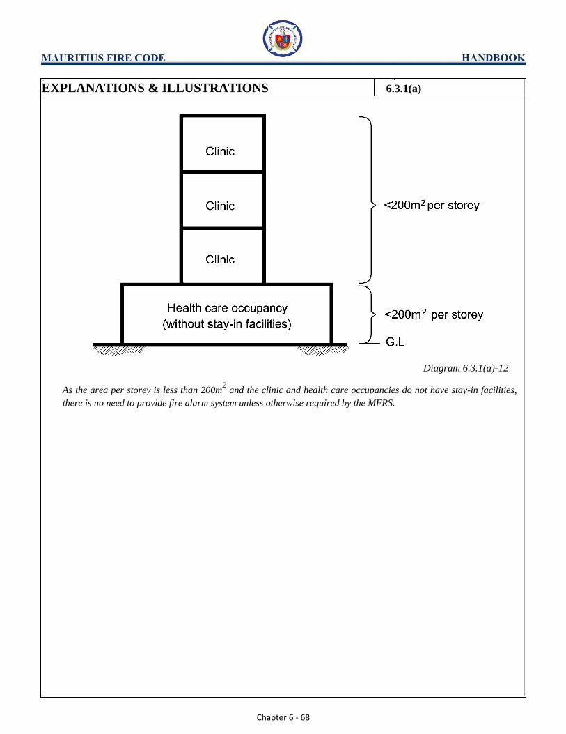
Diagram 6.3.1(a)-12
As the area per storey is less than 200m2 and the clinic and health care occupancies do not have stay-in facilities,
there is no need to provide fire alarm system unless otherwise required by the MFRS.
Chapter 6 - 69
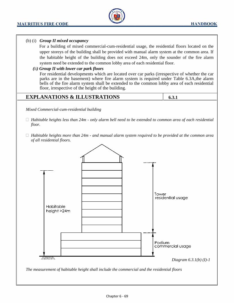
(b) (i) Group II mixed occupancy
For a building of mixed commercial-cum-residential usage, the residential floors located on the
upper storeys of the building shall be provided with manual alarm system at the common area. If
the habitable height of the building does not exceed 24m, only the sounder of the fire alarm
system need be extended to the common lobby area of each residential floor.
(ii) Group II with lower car park floors
For residential developments which are located over car parks (irrespective of whether the car parks are in the basement) where fire alarm system is required under Table 6.3A,the alarm bells of the fire alarm system shall be extended to the common lobby area of each residential floor, irrespective of the height of the building.
EXPLANATIONS & ILLUSTRATIONS 6.3.1
Mixed Commercial-cum-residential building
Habitable heights less than 24m - only alarm bell need to be extended to common area of each residential floor.
Habitable heights more than 24m - and manual alarm system required to be provided at the common area of all residential floors.
Diagram 6.3.1(b) (I)-1
The measurement of habitable height shall include the commercial and the residential floors

Chapter 6 - 70
EXPLANATIONS & ILLUSTRATIONS 6.3.1(b)
Residential building with only first storey shops
- alarm provision exempted
Diagram 6.3.1(b)(i)-2
(1) Where habitable height of building exceeds 24m, manual alarm system is to be provided at the common
area such as lobby and corridor of each residential floor of the resident tower block. The “break the
glass” call point shall be provided in the manner that no occupant needs to run more than 30m to
activate the call point, measured from the entrance door of the unit to the call point. (2) If the habitable height of the building is less than 24m, only the alarm bell of the fire alarm system of the
podium block need be extended to the common area of each residential floor. The sounding level of the
alarm bells shall be above the expected ambient level in each unit. (3) Total fire separation (horizontal) shall be provided between residential floors and commercial floors.
(4) The discharge routes of residential floors shall not go through commercial floors. They shall be
segregated and discharged to the exterior at grade level. (5) Residential slab blocks of habitable heights less than 24m, with only first storey shop usage are not
required to be provided with fire alarm system, subject to:
(i) the footprint of the 1st
storey shop is the same as the residential blocks; and
(ii) The 1st
storey comprises shop units which are individually fire compartmentalised.

Chapter 6 - 71
EXPLANATIONS & ILLUSTRATIONS 6.3.1(b)
Residential block located over car park floors
Diagram 6.3.1(b)(ii)-1&2
Diagram 6.3.1(b)(ii)-3
(1) Alarm bell of the fire alarm system for the car park floors shall be extended to the common area of every
upper residential floor. (2) The sounding level of the alarm bells shall be above the expected ambient level in each residential unit.

Chapter 6 - 72
(c) Notwithstanding (a) above, if the total floor area per storey of a 2 to 4 storey building of any of
the Purpose Group III to VIII exceeds the sizes as stipulated in Column (2) of Table 3.2A , the
building shall be provided with an automatic fire alarm system.
EXPLANATIONS & ILLUSTRATIONS 6.3.1
Diagram 6.3.1(c)
The above diagram shows a typical floor area exceeding 5000m²; accordingly it requires sprinkler protection
for such excessive floor area. By compartmentalising the floor area with each compartment not exceeding
4000m², sprinkler installation will be waived. In its place, automatic fire alarm system is required to be
provided. Therefore, notwithstanding the provision of compartmentation, if the total floor area per storey of a
2 to 4 storey building exceeds 4000m², the building shall be provided with automatic fire alarm system. This
requirement will not apply to a single storey building. The automatic fire alarm system serves to provide early
detection to the occupants. Hence, it allows more time for occupants to evacuate.

Chapter 6 - 73
(d) For dormitories, including workers' dormitories, electrical fire alarm system shall be provided as
follows:
(i) dormitories not exceeding 4-storey, manual fire alarm system is to be provided to comply
with BS 5839;
(ii) dormitories exceeding 4-storey, automatic fire alarm system shall be provided to comply
with BS 5839.
EXPLANATIONS & ILLUSTRATIONS 6.3.1
No illustration
Please refer to Table 6.3A for more details.

Chapter 6 - 74
CHAPTER 6
6.3 ELECTRICAL FIRE ALARM SYSTEM
6.3.2 Fire alarm panel
(a) An electrical fire alarm system of the automatic or manual type shall be provided with a fire alarm
panel to indicate the location of the alarm which has been actuated or operated. Such alarm panel
of location shall be accurate to the maximum allowed alarm group area limitations specified in BS
5839.
EXPLANATIONS & ILLUSTRATIONS
No illustration.
(1) Fire fighters responding to a fire call would first, on arrival at the scene, need to check the fire indicator
board to confirm the location of the alarm, which has been actuated or operated before proceeding to the
fire site. (2) The Fire alarm panel monitors the actuation of detectors, call-points and sprinkler flow switch.
(3) A permanent fire zone chart or mimic panel shall be displayed at the Fire alarm panel location to provide
information on originality of the alarm. The fire zone chart or mimic panel shall be installed in
accordance with the floor or building orientation. All the alarm zones and Fire alarm panel zones if
provided should be clearly depicted on the fire zone chart/mimic panel. Additional information such as,
fire engine access way, location of breeching inlets, fire hydrant, sprinkler control valve, hose reel and fire
extinguisher should be provided on the fire zone chart/mimic panel where applicable. This would help the
fire fighters to identify the location of fire engine access way, breeching inlets etc, when they arrived at the
fire site. (4) Where addressable fire alarm system is used, fire alarm panel shall be provided additional to the
programmable message on display.
Chapter 6 - 75
(b) The associated control and supervisory equipment, indicating equipment, wiring and
arrangement of power supplies for the fire alarm panel shall comply with the requirements in BS
5839. (c) All automatic systems which are activated via the general building alarm shall be connected
directly to the fire alarm panel. (d) The fire alarm panel should be located near the main entrance of the building, in the fire
command centre, in the guardhouse or in the firefighting lobby, if provided, or as may be
required by the MFRS. (e) Sub-fire alarm panel, where provided, shall comply with the requirements in BS 5839 be located
at the fire-fighting lobby, smoke-stop lobby, protected staircase in that order of priority or at the
main point of entry into the area covered by the alarm zone.
EXPLANATIONS & ILLUSTRATIONS 6.3.2
No illustration.
Where fire command centre is not provided, the Fire alarm panel is usually near the main entrance of the
building or in the guardhouse.
Where sub- Fire alarm panels are provided, they shall be located at the fire lift lobby, smoke stop lobby,
protected staircase in that order of priority or at the main point of entry into the area covered by the alarm
zone.

Chapter 6 - 76
CHAPTER 6
6.3 ELECTRICAL FIRE ALARM SYSTEM
6.3.3 Manual Alarm Call Point
(a) In a manual alarm system, except as otherwise exempted in Cl. 6.3.1, the manual call points shall
be provided on every storey of the building or part of the building and shall be so located that no
person need travel more than 30m from any position within the building to activate the alarm. (b) Manual call points should be located on exit routes preferably next to hose reels and in particular
on the floor landings of exit staircases and at exits to the street. In the case where an automatic
fire alarm system is provided, grouping for indication of location of the manual call points shall
comply with the requirements in BS 5839.
(c) Manual call points should be fixed at a height of 1.4m above the floor and shall be located at
easily accessible and conspicuous positions free from obstructions. The installation of the
sounding device shall be in accordance with BS 5839.
(d) Manual break-glass alarm call points can be omitted in carparks, irrespective whether the parking
facility is stand-alone type or forms part of a building.
(e) Subject to compliance with Cl.2.6.2, provision of manual call point on the mezzanine floor of
factory unit is not required provided no person on the mezzanine floor need to travel more than
30m to activate the nearest manual call point located on the main floor.
EXPLANATIONS & ILLUSTRATIONS
(1) Manual call points should be located on: (a) Along exit routes leading to exit staircase;
(b) Adjacent to hose reels; (c) At floor landing of exit staircases; and (d) At exits to the street.
(2) Manual call points shall be so located such that no occupant needs to run more than 30m, measured from
the entrance door of the unit to the manual call point.
Chapter 6 - 77
CHAPTER 6
6.3 ELECTRICAL FIRE ALARM SYSTEM
6.3.4 Automatic fire alarm
Where an automatic fire alarm system is required by this Code, the type, location, spacing and
installation of the detectors shall comply with the requirements in BS 5839.
EXPLANATIONS & ILLUSTRATIONS
No illustration.
Automatic alarm system would not normally be provided to solely Purpose Group II buildings. However, there
is an advantage of providing smoke detectors, as the detectors could detect the generation of smoke from even
incipient fires, hence providing occupants early warning and adequate lead-time in evacuation. Automatic fire
alarm system is required in buildings of more than 4 storeys having commercial cum residential mix, for
example, shops with apartment/maisonette units above.
When selecting the type of detectors, the likely fire behaviour of the contents of each part of the building, the
processes taking place and the design of the building should be considered. The effective coverage of each type
of detectors differs from each other. The location of placing the detectors and the spacing between detectors
shall apply with the requirements in BS 5839. Detectors shall be zoned into alarm group and be properly
wired to achieve electrical supervision of the alarm circuit.

Chapter 6 - 78
CHAPTER 6
6.3 ELECTRICAL FIRE ALARM SYSTEM
6.3.5 Alarm Device
(a) The alarm device, which should normally issue an audible signal unless specifically allowed or
required otherwise by the MFRS, shall be actuated if the electrical fire alarm system is activated
or operated. The type, number and location of the alarm device shall comply with the
requirements in BS 5839.
(b) The fire alarm sounder shall have a sound that is readily distinguishable from any other alarm
system.
(c) All sounders in the building should be actuated simultaneously in the event of activation.
However, in cases permitted or required by the MFRS where the operation of alarm sounders are
grouped or activated in stages, the arrangement shall comply with the requirements in BS 5839.
(d) (i) In discos, night clubs, other places of entertainment outlets or areas where audible alarms
may be ineffective (background noise is excessive), visual alarm signals shall be provided.
In general, visual signals shall not be used in place of audible alarms. The intensity of the
light shall be sufficient to draw the attention of people in the vicinity, or
(ii) The sound system in discos, night clubs and other places of entertainment shall be
electrically interlocked with the fire alarm system to enable the sound to be automatically
cut-off in the event that the fire alarm system is activated.
EXPLANATIONS & ILLUSTRATIONS
No illustration.
It is important that the sounding from the electrical fire alarm system, for example, installed in the
office/shop/places of public resort, should be audible and readily distinguishable to all occupants.
All fire alarm sounders must generate the continuous ringing tone of the bell. In special environment where the
use of bell tone is impractical or in area of high background noise level, other tone may be used, in which case
the MFRS permission must be sought.
The number of fire alarm sounders used should be sufficient to produce a minimum sound level of either 65 db,
or 5 db above any other noise likely to persist for a period longer than 30 seconds, whichever is greater, in all
parts of the buildings which are normally occupied.
Chapter 6 - 79
EXPLANATIONS & ILLUSTRATIONS 6.3.5
In areas where a normal type of sounder may be ineffective, e.g. where the background noise is excessive,
where the occupants are deaf or where hearing protection is likely to be worn, visual signals shall be
provided. In general, visual signals shall not be used in place of audible alarms. The intensity of the light shall
be sufficient to draw the attention of people in the vicinity.
In discos, night-club and other places of entertainment, it is recommended that the sound system be electrically
interlocked with the fire alarm system to enable the sound system to be automatically cut-off in the event that
the fire alarm is activated.

Chapter 6 - 80
CHAPTER 6
6.3 ELECTRICAL FIRE ALARM SYSTEM
6.3.6 Alarm system for cinema
A theatre or cinema shall be provided with an electrical fire alarm system of the manual type
complying with the following:
(a) The manual alarm system shall be installed in the lobbies and other areas adjoining the hall and
shall be connected to a fire station through an approved alarm monitoring station, and
EXPLANATIONS & ILLUSTRATIONS
No illustration.
Manual alarm call points are required to be provided in the lobbies and other areas adjoining the cinema hall.
Occupants escaping from a fire in the hall could break the glass of the call point to activate the alarm.
Manual alarm call points and sounding devices are not allowed to be installed in the hall owing to the nature
of the occupancy, the lighting level and seating arrangement. The sounding of any alarm bells in the cinema
hall when a show is in progress would cause confusion and panic to the occupants.
Chapter 6 - 81
(b) Visual and audible alarm indicators shall be installed in the projection room and in another room
where a responsible person is readily available to alert the audience in case of a fire, and
EXPLANATIONS & ILLUSTRATIONS 6.3.6
No illustration.
In place of general sounding alarm, visual alarm indicator such as beacon lights and audible alarm indicator,
instead of alarm bells are required to be installed in the projection room and cinema manager office to alert
both the projectionists and the manager immediately, so that occupants in the cinema hall would be advised
through the projection screen and or public address system to evacuate the hall in an orderly and calm
manner.

Chapter 6 - 82
(c) The provision of the fire protection system in cinema which forms part of the building shall be
similar to that of the building.
EXPLANATIONS & ILLUSTRATIONS 6.3.6
No illustration.
In situations where the cinema hall or halls are located within a commercial building, the fire protection
system of the commercial building such as sprinkler system, would be required to be extended to cover the
cinema hall, lobbies, projection room and other ancillary areas.

Chapter 6 - 83
CHAPTER 6
6.3 ELECTRICAL FIRE ALARM SYSTEM
6.3.7 Connection to fire station
The electrical fire alarm system required to be installed in a building or premises under this clause
shall be connected to a fire station through an approved alarm monitoring station when the building
or premises is-
(a) Health care occupancy, hotel or other such like occupancy,
(b) An oil refinery, oil depot, general warehouse, chemical plant or other high hazard factory or
premises,
(c) A theatre, cinema or concert hall as specified in Cl.6.3.6, or
(d) (i) A building required under the provisions of this code to be protected by an automatic fire
alarm or fire extinguishing system. (ii) Notwithstanding the provision in Cl.6.3.3 (d) if a car park in a building is provided with both
manual and automatic fire alarm system, then the manual fire alarm need not be connected to
the fire station through an approved alarm monitoring company.
EXPLANATIONS & ILLUSTRATIONS
(1) Buildings under purpose group II are usually not provided with automatic fire alarm system or automatic
sprinkler system except in basement car parking.
(2) In situations where automatic sprinkler system is proposed to meet the fire safety requirements, for
example, travel distances, then sub-clause (d) above would be applicable.

Chapter 6 - 84
EXPLANATIONS & ILLUSTRATIONS 6.3.7(d)
Diagram 6.3.7(d)
General warehouse refers to general storage other than explosive or flammable storage. In the above building,
which is only provided with manual fire alarm system, the system is to be connected through an approved
alarm monitoring company. Where a building is not the abovementioned premises, the owner can opt to
connect the alarm system to the approved alarm monitoring station.
Relaxation is only granted to carpark building where both manual and automatic fire alarm system are
provided, the manual fire alarm need not be connected to the fire station through an approved alarm
monitoring company.
Under Cl. 6.3.3(d) manual call point is not required to be provided in carpark, irrespective whether it is a
stand alone or forms part of a building.
The main reasons for the above relaxation are that carparks are only used when people need to park or
retrieve their cars. The occupant load in carparks would be very low and normally transient in nature. If there
is a fire in a carpark, there might not be any occupant around to activate the fire alarm call point. In addition,
in many carparks, fire alarm call points were frequently activated by mischievous people during the night.
Chapter 6 - 85
CHAPTER 6
6.3 ELECTRICAL FIRE ALARM SYSTEM
6.3.8 Sprinkler protected building
Where sprinkler system is required by this Code, provision of automatic thermal/smoke detectors in
sprinkler protected premises will be exempted except where such detectors are required to activate or
operate the sprinkler or other systems.
EXPLANATIONS & ILLUSTRATIONS
No illustration.
Where sprinkler system is provided in any building, there is no necessity to provide automatic fire alarm
system (heat or smoke detection system). Exception is for electrical rooms, AHU room, lift motor room, battery
room, MDF room, PABX room where sprinkler system is replaced by electrical fire alarm system. Smoke
detectors are also required to be installed in sprinkler protected buildings to operate the smoke control system
in atria, smoke purging system or control system in basement occupancies.

Chapter 6 - 86
CHAPTER 6
6.4 SPRINKLER INSTALLATION
6.4.1 General
The following shall be provided with an automatic sprinkler system:
(a) Whenever compartmentation requirements under Chapter 3 of this Code cannot be complied
with.
EXPLANATIONS & ILLUSTRATIONS
The provision of automatic sprinkler system is required in residential buildings under purpose group II under
the following conditions:
(1) Compartmentation requirements under chapter 3 of the Fire Code cannot be complied with, for example, a
building exceeding 24m in habitable height having 3-levels maisonette or penthouse units, or (2) Residential apartment/maisonette or penthouse unit being located within a commercial tower block
exceeding 24m in habitable height.
Diagram 6.4.1(a)-1 Residential building exceeding 24m habitable height
Clause 3.2.4 of the fire code permits only residential maisonette or penthouse to have maximum 2-storey levels
above 24m habitable height. In designing 3 floors per unit, it would be contravening the compartmentation
requirement under Table 3.2A of Chapter 3. To overcome the problem, automatic sprinkler system should be
provided to the whole building.
Chapter 6 - 87
EXPLANATIONS & ILLUSTRATIONS 6.4.1(a)
The provision of automatic sprinkler system is required in factory or warehouse under the following
conditions:
(1) Compartmentation requirements under Chapter 3 of the Fire Code cannot be complied with, a building not
exceeding 24m in habitable height having more than 3 –levels or excessive cubical extent or floor area. (2) Engineered smoke control system is required to be installed. (3) High bay storage warehouse
Clause 3.2.4(a) of the fire code permits max. 3 storeys to form a single compartment up to a habitable height
of 24m. In designing more than 3 floors per compartment, it would be a breaching the compartmentation
requirement. To overcome the problem, automatic sprinkler system should be provided to the whole building.
However, building owners are at liberty to provide the sprinkler system to their buildings as an added fire
safety. The system could be used as a trade-off for extended travel distances.
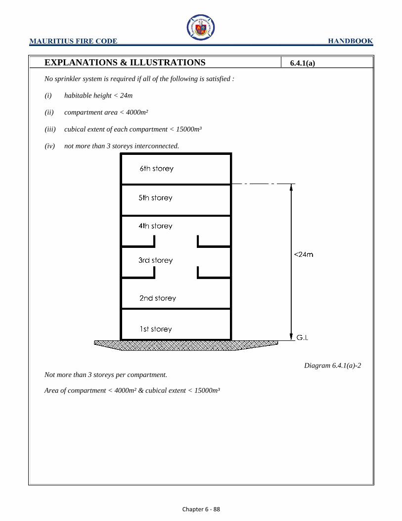
Chapter 6 - 88
EXPLANATIONS & ILLUSTRATIONS 6.4.1(a)
No sprinkler system is required if all of the following is satisfied :
(i) habitable height < 24m
(ii) compartment area < 4000m²
(iii) cubical extent of each compartment < 15000m³
(iv) not more than 3 storeys interconnected.
Diagram 6.4.1(a)-2 Not more than 3 storeys per compartment.
Area of compartment < 4000m² & cubical extent < 15000m³
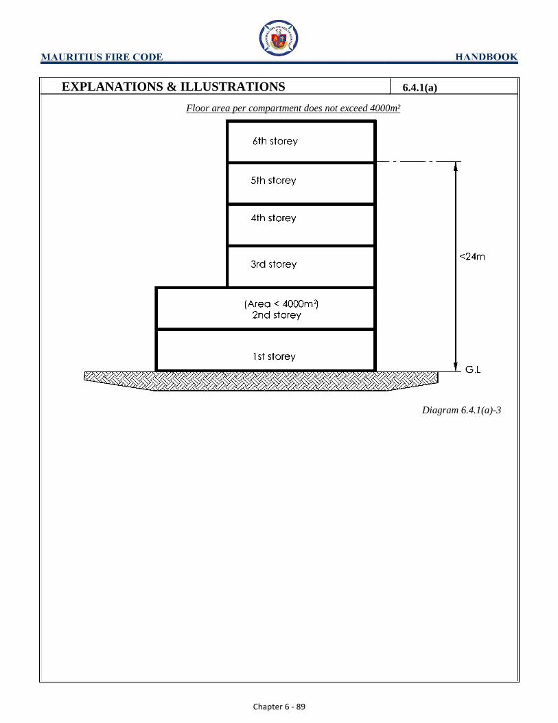
Chapter 6 - 89
EXPLANATIONS & ILLUSTRATIONS 6.4.1(a)
Floor area per compartment does not exceed 4000m²
Diagram 6.4.1(a)-3

Chapter 6 - 90
EXPLANATIONS & ILLUSTRATIONS 6.4.1(a)
Cubical extent per compartment does not exceed 15000m³
Diagram 6.4.1(a)-4
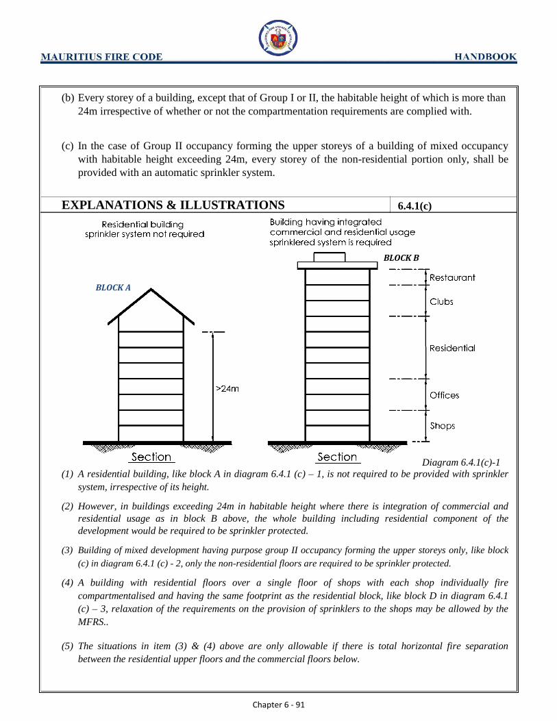
Chapter 6 - 91
(b) Every storey of a building, except that of Group I or II, the habitable height of which is more than
24m irrespective of whether or not the compartmentation requirements are complied with.
(c) In the case of Group II occupancy forming the upper storeys of a building of mixed occupancy
with habitable height exceeding 24m, every storey of the non-residential portion only, shall be
provided with an automatic sprinkler system.
EXPLANATIONS & ILLUSTRATIONS 6.4.1(c)
BLOCK B
BLOCK A
Diagram 6.4.1(c)-1
(1) A residential building, like block A in diagram 6.4.1 (c) – 1, is not required to be provided with sprinkler
system, irrespective of its height. (2) However, in buildings exceeding 24m in habitable height where there is integration of commercial and
residential usage as in block B above, the whole building including residential component of the
development would be required to be sprinkler protected. (3) Building of mixed development having purpose group II occupancy forming the upper storeys only, like block
(c) in diagram 6.4.1 (c) - 2, only the non-residential floors are required to be sprinkler protected. (4) A building with residential floors over a single floor of shops with each shop individually fire
compartmentalised and having the same footprint as the residential block, like block D in diagram 6.4.1
(c) – 3, relaxation of the requirements on the provision of sprinklers to the shops may be allowed by the
MFRS..
(5) The situations in item (3) & (4) above are only allowable if there is total horizontal fire separation
between the residential upper floors and the commercial floors below.

Chapter 6 - 92
EXPLANATIONS & ILLUSTRATIONS 6.4.1(c)
Residential Block Over Shopping Podium
BLOCK C
Diagram 6.4.1(c)-2
Residential floors over Single Shopping Floor
BLOCK D
Diagram 6.4.1(c)-3
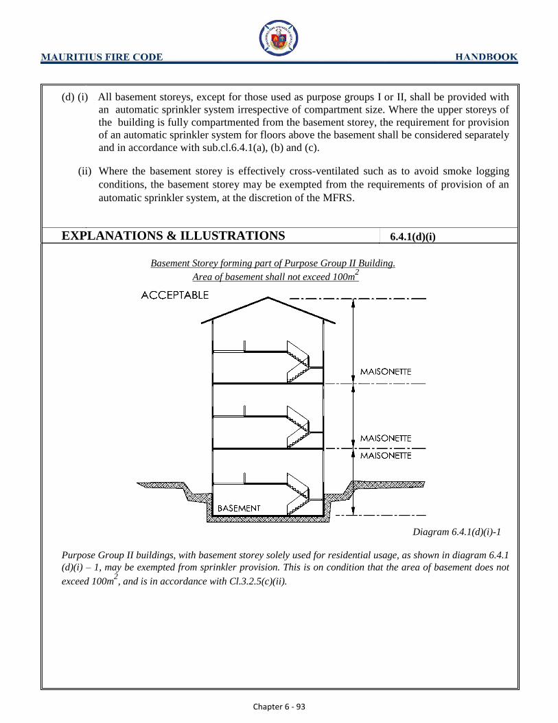
Chapter 6 - 93
(d) (i) All basement storeys, except for those used as purpose groups I or II, shall be provided with
an automatic sprinkler system irrespective of compartment size. Where the upper storeys of
the building is fully compartmented from the basement storey, the requirement for provision
of an automatic sprinkler system for floors above the basement shall be considered separately
and in accordance with sub.cl.6.4.1(a), (b) and (c).
(ii) Where the basement storey is effectively cross-ventilated such as to avoid smoke logging
conditions, the basement storey may be exempted from the requirements of provision of an
automatic sprinkler system, at the discretion of the MFRS.
EXPLANATIONS & ILLUSTRATIONS 6.4.1(d)(i)
Basement Storey forming part of Purpose Group II Building.
Area of basement shall not exceed 100m2
Diagram 6.4.1(d)(i)-1
Purpose Group II buildings, with basement storey solely used for residential usage, as shown in diagram 6.4.1
(d)(i) – 1, may be exempted from sprinkler provision. This is on condition that the area of basement does not
exceed 100m2, and is in accordance with Cl.3.2.5(c)(ii).

Chapter 6 - 94
EXPLANATIONS & ILLUSTRATIONS 6.4.1(d)(i)
Diagram 6.4.1(d) (I)-2
However a residential building with 2 basements and 1st
storey forming one residential compartment (diagram 6.4.1 (d)(i) –2), is unacceptable, regardless of sprinkler provision. Cl.3.2.5(c)(ii) and 3.2.5(d) stipulate that for
any compartment below pavement level, no compartment shall exceed 100m2 and comprise more than one
storey respectively.

Chapter 6 - 95
(d) (iii) In the case of residential development located over basement carpark, relaxation on the
provision of these sprinkler system and smoke purging systems to the basement carpark may
be granted by the MFRS if the following conditions are satisfactorily fulfilled:
(1) basement car parking shall consist of one level only;
EXPLANATIONS & ILLUSTRATIONS 6.4.1
Diagram 6.4.1(d) (iii) (1)
Waiver for sprinkler and smoke purging system in this situation can be considered.
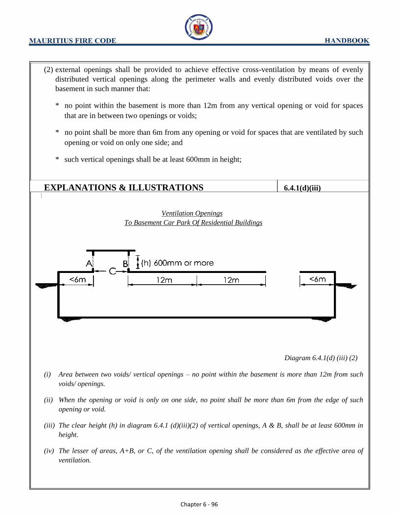
Chapter 6 - 96
(2) external openings shall be provided to achieve effective cross-ventilation by means of evenly
distributed vertical openings along the perimeter walls and evenly distributed voids over the
basement in such manner that:
* no point within the basement is more than 12m from any vertical opening or void for spaces
that are in between two openings or voids;
* no point shall be more than 6m from any opening or void for spaces that are ventilated by such
opening or void on only one side; and
* such vertical openings shall be at least 600mm in height;
EXPLANATIONS & ILLUSTRATIONS 6.4.1(d)(iii)
Ventilation Openings To Basement Car Park Of Residential Buildings
Diagram 6.4.1(d) (iii) (2)
(i) Area between two voids/ vertical openings – no point within the basement is more than 12m from such
voids/ openings.
(ii) When the opening or void is only on one side, no point shall be more than 6m from the edge of such
opening or void.
(iii) The clear height (h) in diagram 6.4.1 (d)(iii)(2) of vertical openings, A & B, shall be at least 600mm in
height.
(iv) The lesser of areas, A+B, or C, of the ventilation opening shall be considered as the effective area of
ventilation.

Chapter 6 - 97
(e) total aggregate area of these voids and vertical openings shall be not less than 20% of the total
basement floor area;
EXPLANATIONS & ILLUSTRATIONS 6.4.1(d)(iii)(c)
Diagram 6.4.1(d) (iii) (c)
Total aggregate area of voids and vertical openings shall not be less than 20% of the floor area.
i.e. 20% of A > A1 + { lesser of (A2 + A3) or A6 }+ A4 + A5
(Where A is the area of basement, and A1 to A6 are areas of ventilation openings)

Chapter 6 - 98
(f) Automatic fire alarm system shall be provided to the basement carparks with extension of alarm
bells to the common/lobby areas of the upper storeys in accordance with cl.6.3.1 (a) and (b) (ii).
EXPLANATIONS & ILLUSTRATIONS 6.4.1(d) (iii) (d)
Diagram 6.4.1(d) (iii) (d)-1
Basement shall be provided with automatic fire alarm system. The alarm bells of the system shall be extended
to the common / lobby areas of the upper storeys.

Chapter 6 - 99
EXPLANATIONS & ILLUSTRATIONS 6.4.1(d) (iii) (d)
Diagram 6.4.1(d) (iii) (d)-2
All basement storeys shall be provided with automatic sprinkler system irrespective of the compartment size.
(a) floor area and cubical extent of each storey do not exceed 4000m² and 15000m³ respectively;
(b) Habitable height of the highest floor does not exceed 24m.
(c) Upper storeys are fully compartmented from the basement storey.

Chapter 6 - 100
(g) Exemption of sprinkler protection
With the exception of industrial buildings, such as factories (purpose group VI), warehouses and
storage depots (purpose group VIII), the following areas are exempted from sprinkler protection
in a sprinklered building:
(i) Canopies/Car porches (1) Such areas are used solely for the purpose of passengers pick-up and drop-off point; and
(2) There shall be no commercial activities or storage within these areas; and
(3) Cut-off sprinklers and fire rated wall are not required to be provided to separate the
sprinklered and non-sprinklered areas.
(ii) External corridors not exceeding 4m in width provided there are no commercial activities or
storage within these areas. (iii) Atrium ceilings which exceed the height of 12m, measured from the finished floor level of
the atrium floor to the ceilings of the atrium roof or to the level of half the vertical height of
the ceilings of the atrium roof in the case of irregular roof profile. In lieu of the provision of
sprinklers, approved effective detectors (e.g. smoke, infra-red, etc) shall be installed in
accordance with the approved standards and there shall be no commercial activities or
storage within the floor spaces below the atrium roofs. (iv) External open-sided link ways not exceeding 5m in width provided there are no commercial
activities or storage within these areas.
EXPLANATIONS & ILLUSTRATIONS 6.4.1
Diagram 6.4.1(e) (ii)
The width of the external corridor shall not exceed 4m, measured from the external wall of the building to the
edge of the roof cover of the corridor.

Chapter 6 - 101
EXPLANATIONS & ILLUSTRATIONS 6.4.1(e)
Diagram 6.4.1(e)(iii)-1
Diagram 6.4.1(e)(iii)-2
In the above diagram, h1 and h2 represents the height of the Atrium Roof.

Chapter 6 - 102
CHAPTER 6
6.4 SPRINKLER INSTALLATION
6.4.2 Installation
Installation of the sprinkler system and its associated water supply, control and testing requirements
shall comply with the BS EN 12845.
EXPLANATIONS & ILLUSTRATIONS
No illustration.
(a) Sprinkler system to maisonette or apartment units under purpose group II is not a requirement. However,
where basement carpark cannot comply with the requirements of Cl.6.4.1 and Cl.3.2.5, sprinkler system
shall be provided as illustrated under Purpose Group VIII.
(b) Building owners are also at liberty to provide the sprinkler system as an added fire safety. The system
could be used as a trade-off for extended travel distances and other fire safety requirements at the
discretion of the MFRS.

Chapter 6 - 103
CHAPTER 6
6.4 SPRINKLER INSTALLATION
6.4.3 Connection to fire station
(a) The sprinkler system shall be electrically monitored so that on the operation of any sprinkler
head, the fire signal is automatically transmitted to a fire station through an approved alarm
monitoring station.
(b) Installation of fire pumps for sprinkler system shall comply with requirements of BS EN 12845.
Sprinkler pumps shall be installed within a fire compartmented fire pump room, whose fire rating
shall be in accordance with Table 6.4A. The sprinkler pump room floor level shall not be lower
than the main floor level.
Sprinkler control valve(s) shall be located in the following order of priority:
(i) facing external within close proximity to Fire Command Centre;
(ii) within fire-fighting lobby/smoke-stop lobby; and
(iii) within sprinkler pump room that has proper access; and
(iv) within fire compartmented enclosure located near to fire-fighting stair and readily accessible
from the common areas.
EXPLANATIONS & ILLUSTRATIONS
No illustration.
Where the provision of the sprinkler system to a building is a requirement under the fire code or at the
direction of the MFRS, the system shall be linked to an approved alarm monitoring station. All transmitting
equipment shall be approved by the telecommunication authority. The transmitting equipment shall have at
least the following features:
(a) Transmission of signal via “leased-line”
(b) Alternative transmission path via telephone which serve as back-up
(c) Indications for status of “leased-line”, phone line, system test, alarm, power supply, and unauthorised
opening of the panel box
“Leased- line” shall be the primary means of signal transmission with an automatic switch over to normal
telephone line upon leased-line failure.

Chapter 6 - 104
CHAPTER 6
6.4 SPRINKLER INSTALLATION
6.4.4 Special Purpose Rooms
(a) Where a building is required to be provided with an automatic sprinkler system under this Code,
parts of the building which are used for purposes stipulated in Table 6.4A shall be compartmented
in accordance with columns 3(a) and 3(b) of the table. Exemptions of sprinkler provision for such
rooms or spaces are indicated (Ex) in column 3(c) of the table.
EXPLANATIONS & ILLUSTRATIONS
No illustration.
See Table 6.4A.
Table 6.4A is attached. Openings of these special purpose rooms for example lift motor room at the roof top
need not to be provided with fire resistance door as stipulated in Table 6.4A. This arrangement is allowed only
if the door is located at the external wall and opened directly to the exterior and subject to compliance with
Clause 3.5 to be unprotected opening. In addition there is no possible fire risk to other room usage.
Compartmentation and door rating of the special purpose rooms shall not be less than the fire resistance of the
elements of structure of the building where the room is located. For storeroom, kitchen, emergency lighting
battery room and fire command centre, the fire resistance for the compartment walls, floors/ceilings and doors
shall have the min. periods specified in Table 6.4A.
Chapter 6 - 105
(b) Where a building is not required to be provided with an automatic sprinkler system under this
Code, special purpose rooms stipulated in Table 6.4A shall be compartmented in accordance with
columns 2(a) and 2(b).
EXPLANATIONS & ILLUSTRATIONS 6.4.4
No illustration.
See Table 6.4A.
See Table 6.4A. Columns 2(a) and 2(b) spell out the minimum periods of fire resistance rating for storeroom,
kitchen, emergency lighting battery room and fire command centre. Actual period may be higher, and shall
comply with the elements of structure of the building where the room is located.

Chapter 6 - 106
(c) Where automatic sprinklers are to be replaced by an automatic fire extinguishing system to protect
special purpose rooms for the use as communication nerve centres, data process centres and
process control rooms composing of high value computers or telecommunication equipment, the
enclosure to the hazard or occupancy shall comply with the following:
(i) it shall be constructed to have minimum 1-hour fire resistance rating;
(ii) any door opening shall be protected with minimum 1-hour fire door;
(iii) it shall not be provided with more than 2 exits;
(iv) the direct travel distance to any exit door of the enclosure shall not exceed 15m; and
(v) The fire extinguishing system using clean agent shall conform to Cl.6.5.2
EXPLANATIONS & ILLUSTRATIONS 6.4.4
Diagram 6.4.4(c)
Since the sprinkler heads in the room would be omitted, it is necessary to use the direct one-way travel
distance requirement to limit the room size, hence the direct one-way travel distance of maximum 15m shall be
strictly complied with.

Chapter 6 - 107
CHAPTER 6
6.4 SPRINKLER INSTALLATION
6.4.5 Water mist system
Water mist system may be permitted as a substitute of automatic sprinklers in sprinkler protected
buildings provided that the following requirements are complied with:
(a) Water mist system shall be a propriety design that has been tested to meet the performance
requirements of a standard acceptable to the MFRS;
(b) Design and installation of water mist system shall conform to BS 8458; and
(c) Components of water mist system shall be listed by a recognised testing laboratory.
EXPLANATIONS & ILLUSTRATIONS
No illustration.

Chapter 6 - 108
CHAPTER 6
6.4 SPRINKLER INSTALLATION
6.4.6
In multi-storey buildings under Purpose groups II, III, IV, V, VI, VII & VIII not exceeding 24m in
habitable height, where any car parking area above ground is provided with natural ventilation in
accordance with Cl.3.2.8(c), the provision of automatic sprinkler to the car parking area is not
required provided:
(a) An automatic fire alarm system shall be provided to the car parking area under Purpose Groups
III, IV, V & VII; and
(b) Manual fire alarm system shall be provided to the car parking area under Purpose Group II
subject to Table 6.3A.
EXPLANATIONS & ILLUSTRATIONS
Diagram 6.4.6
In the above situation where car parking checks form part of the multi storey development, having a habitable
height greater than 24m, automatic sprinkler system is required to be provided to cover the whole building
including the car parking decks.
Chapter 6 - 109
CHAPTER 6
6.4 SPRINKLER INSTALLATION
6.4.7
The “Guidelines on Reduced Water Storage for Automatic Fire Sprinkler System in Buildings” are
given in Appendix (9). It provides an acceptable design approach for the installation of sprinkler
systems in both new and existing buildings under ordinary hazard category classification under BS
EN 12845:
EXPLANATIONS & ILLUSTRATIONS
No illustration.
Please see the guidelines under Appendix (9).
Chapter 6 - 110
CHAPTER 6
6.5 FIXED AUTOMATIC FIRE EXTINGUISHING SYSTEMS
6.5.1 Installation
Installation of any fixed automatic fire extinguishing systems which are not deemed to be required by
this Code shall not be accepted as substitute of any provision stipulated in this Code unless otherwise
approved as such by the MFRS. Such systems will be considered as additional protection for property
safety and their installation shall not adversely affect the performance of the stipulated systems.
EXPLANATIONS & ILLUSTRATIONS
No illustration.
Chapter 6 - 111
CHAPTER 6
6.5 FIXED AUTOMATIC FIRE EXTINGUISHING SYSTEM
6.5.2
Design and installation of such automatic fire extinguishing systems shall comply with corresponding
Code of Practice acceptable by the MFRS.
EXPLANATIONS & ILLUSTRATIONS
No illustration.
Fixed automatic fire extinguisher systems include, fixed water spray, gas flooding system & wet chemical
suppression system for kitchen hood etc.
Where a building is provided with automatic sprinkler system, the provision of any of the above system for
added protection to property shall not affect the operation and performance of the sprinkler system in the
building. For example, a computer room is provided with gas flooding system, in-addition to the sprinkler
system.
Any fixed automatic fire extinguishing system such as gas flooding system which is not deemed to be a
requirement under the fire code for a particular building shall not be accepted as replacement or substitute of
any system required by the fire code unless approved by MFRS.
Such automatic fire extinguishing systems if not properly installed or incorrectly maintained could pose
additional hazard to the occupants. Warning signs are to be visibly displaced at strategic position. Features
such as stopping of air handling units or other safety features are needed to be incorporated in the installing of
the above. QPs are to seek clarification/consultation with MFRS before carrying out any such installation in
their development.

Chapter 6 - 112
CHAPTER 6
6.6 LIFTS
A set of requirements using lifts for building evacuation during emergency is drawn up at Appendix 18 &
Appendix 19. These requirements are applicable to all buildings except residential developments
6.6.1 Hoist way Ventilation
Lift hoist ways shall be vented in accordance with the BS EN 81-20
EXPLANATIONS & ILLUSTRATIONS
Diagram 6.6.1-1
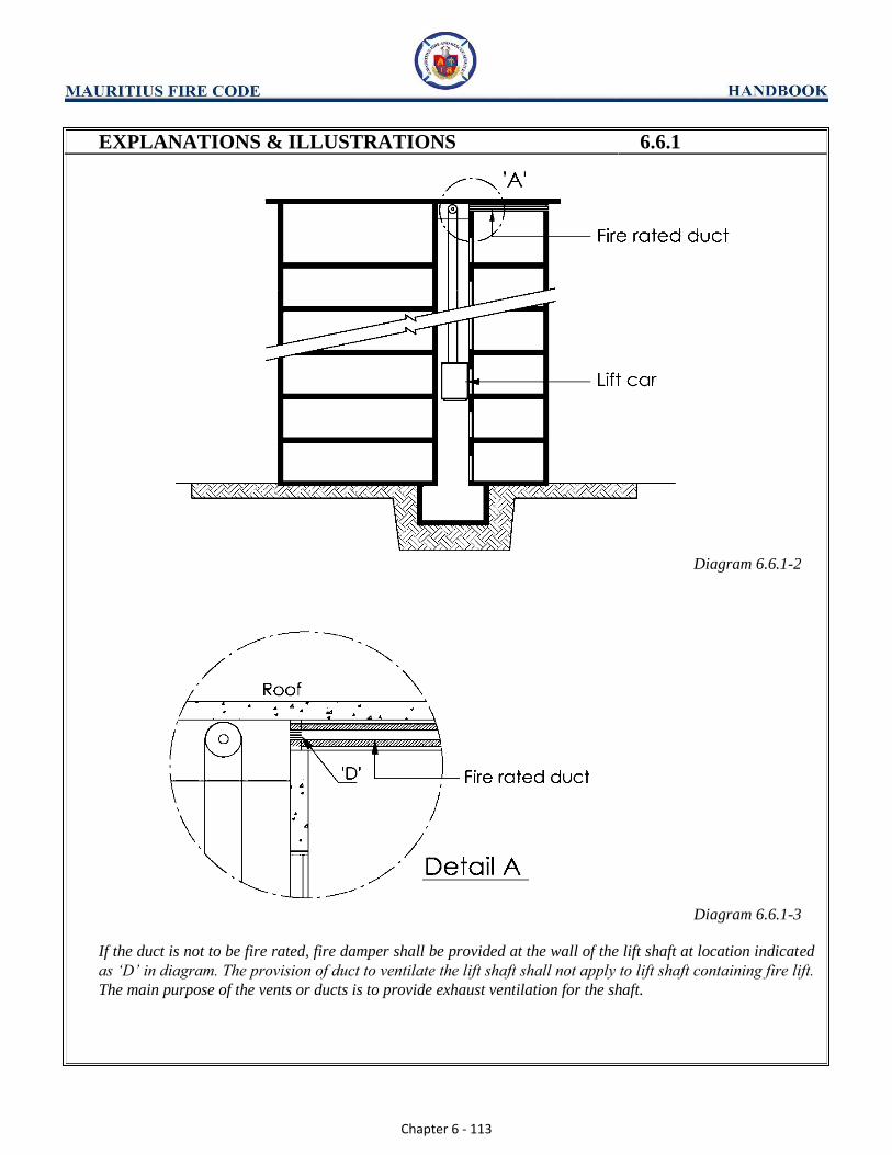
Chapter 6 - 113
EXPLANATIONS & ILLUSTRATIONS 6.6.1
Diagram 6.6.1-2
Diagram 6.6.1-3
If the duct is not to be fire rated, fire damper shall be provided at the wall of the lift shaft at location indicated
as ‘D’ in diagram. The provision of duct to ventilate the lift shaft shall not apply to lift shaft containing fire lift.
The main purpose of the vents or ducts is to provide exhaust ventilation for the shaft.

Chapter 6 - 114
CHAPTER 6
6.6 LIFTS
6.6.2 Emergency power supply
(a) Emergency power supply for lighting, ventilation and alarm systems for all passenger lifts shall
comply with the requirements in BS EN 81-20.
EXPLANATIONS & ILLUSTRATIONS
No illustration.
Emergency power supply (EPS) from a separate rechargeable source shall be provided for all passenger lifts.
This emergency supply shall comply with BS EN 81-20. EPS for lighting, ventilation, ventilation and alarm
system for the lift cars is to allow the passengers in the lift car to activate the alarm bell for help, and to ensure
adequate lighting/ventilation while they wait for rescue during a power failure.
Emergency Operation of Lift
1. Lifts that are commonly found in buildings under Purpose Group VI and VIII are electrical passenger lifts,
fire lifts and good lifts.
2. Although the current BS EN 81-20 does not specifically require the installation of generator set to provide
secondary power supply to the above lifts, however in the case of multi-storey industrial buildings exceeding
24m in habitable height, it is recommended that the generator set be provided to operate the lifts during
emergency. If emergency generator is not available, power supply to passenger lift and fire lift shall be
provided via a sub-main circuit to enhance reliability.
3. For lifts not powered by emergency generator, an Automatic Rescue Device (ARD) should be incorporated
in the lift system to bring the lifts to the nearest lift landing and open its door upon power failure.
4. Where an automatic mains failure standby generating system is installed, it shall have sufficient capacity to
cover the special emergency operations of passenger lifts, such as:
(a) In the event of power failure in buildings
In the event of power failure or power interruption, the supply to the lift(s) shall be automatically
switched over to emergency power supply and the lift(s) shall be brought to the designated floor
commencing with the fire lift(s), and park there with their door(s) remaining open until all lift(s) have
been brought down to the designated floor. Thereafter, one or more lift may resume operation
depending on the capacity of the emergency generating plant. In addition to the fire lift, normal
operation of the lift shall be automatically reset on the return of normal power supply.
Chapter 6 - 115
EXPLANATIONS & ILLUSTRATIONS 6.6.2(a)
(b) In the event of fire in buildings
In the event of fire when any one of the fire detection devices is activated, the lift(s) shall be brought to
the designated floor and shall park there with door(s) remaining open. In the event there is fire on the
designated floor, the lift will be brought to the second designated floor. The lift(s) shall automatically
be rendered inoperative after it has been brought to the designated floor or where applicable, the
second designated floor. Normal operation of the lift(s) shall be automatically reset after the
deactivation of the fire detectors and the resetting of the fire alarm panel or by the operation of a key
switch, if such a switch is provided.
(c) In the event of power failure and fire in buildings
In the event of power failure and fire, the operation of the lift(s) shall be in accordance with para4 (b)
and the power supply shall be from the “mains failure” generating plant.
Footnote: where lifts serve basement occupancies, homing of lifts to designated floor by generator supply is
required.

Chapter 6 - 116
(b) Buildings which require the provision of standby generating plant for special emergency
operations. Provision for special emergency operation for lifts shall comply with the requirements in BS EN 81 –
20 for the following:
(i) Public buildings;
(ii) Buildings under Purpose Group II exceeding the habitable height of 60m;
(iii) Buildings under Purpose Group II where the passenger lifts serve the upper storey residential
floors and the non-residential basement;
(iv) Mixed developments where the passenger lifts serve both the residential and non-residential
floors;
(v) Industrial buildings under Purpose Group VI and VIII, which are multi-storey.
(vi) All basement occupancies.
EXPLANATIONS & ILLUSTRATIONS 6.6.2
No illustration.
(1) Lifts that are commonly found in buildings under Purpose Group IV, V and VII are electrical passenger
lifts, fire lifts and good lifts.
(2) The current BS EN 81-20 requires the installation of generator set to provide secondary power supply to
passenger lifts and fire lifts.
(3) Where an automatic “mains failure” generating plant is installed, it shall have sufficient capacity to cover
the special emergency operations of passenger lifts, such as:
(a) In the event of power failure in buildings
In the event of power failure or power interruption, the supply to the lift(s) shall be automatically switched
over to emergency power supply and the lift(s) shall be brought to the designated floor commencing with
the fire lift(s), and shall park there with their door(s) remaining open until all lift(s) have been brought
down to the designated floor. Thereafter, one or more lift may resume operation depending on the capacity
of the emergency generating plant. In addition to the fire lift, normal operation of the lift shall be
automatically reset on the return of normal power supply.

Chapter 6 - 117
EXPLANATIONS & ILLUSTRATIONS 6.6.2(b)
(b) In the event of fire in buildings
In the event of fire when any one of the fire detection devices is activated, the lift(s) shall be brought to
the designated floor and shall park there with door(s) remaining open. In the event there is fire on the
designated floor, the lift will be brought to the second designated floor. The lift(s) shall automatically be
rendered inoperative after it has been brought to the designated floor or where applicable, the second
designated floor. Normal operation of the lift(s) shall be automatically reset after the deactivation of the
fire detectors and the resetting of the fire alarm panel or by the operation of a key switch, if such a switch
is provided.
(c) In the event of power failure and fire in buildings
In the event of power failure and fire, the operation of the lift(s) shall be in accordance with para 3(b)
and the power supply shall be from the “mains failure” generating plant.
Chapter 6 - 118
(c) The power supply to the lift shall be connected to a sub-main circuit exclusive to the lift and
independent of any other main or sub-main circuit. The power cables serving the lift installation
shall be routed through an area of negligible fire risk.
EXPLANATIONS & ILLUSTRATIONS 6.6.2
No illustration

Chapter 6 - 119
CHAPTER 6
6.6 LIFTS
6.6.3 Fire lift
(a) With the exception of Purpose Group I and II buildings, all other buildings shall be provided with
at least two fire lifts if the habitable height exceeds 24m. See appendix 19 on the design details.
For Purpose Group II buildings, at least one fire lift shall be provided if the habitable height
exceeds 24m.
All buildings shall also be provided with at least two fire lift if the depth of the basement exceeds
9m below the average ground level.
The fire lift(s) shall be contained within a separate protected shaft or a common protected shaft
containing other lifts subject to such other lifts being served at each storey by the fire fighting
lobby, which is required by the provisions of Cl.2.2.13 (b) of this Code.
EXPLANATIONS & ILLUSTRATIONS
Diagram 6.6.3(a)-1
Fire lift is required as the habitable height exceeded 24m.

Chapter 6 - 120
EXPLANATIONS & ILLUSTRATIONS 6.6.3(a)
Situations requiring fire lift
Diagram 6.6.3(a)-2 Diagram 6.6.3(a)-3
(1) In diagram 6.6.3(a)-2, fire lift is required to serve the basement floors as the depth of the basement is more
than 9m below the average ground level.
(2) In diagram 6.6.3(a)-3, the fire lift is required to serve the basement, even though it is less than 9m in
depth. Where a building is required to be provided with a fire lift, the lift shall serve all floors, upper
storeys and basement(s), in a vertical shaft running through the entire building.

Chapter 6 - 121
(b) A fire lift shall be adjacent and accessible to an exit staircase and be approached by a fire-
fighting lobby at each storey. The fire lift shaft shall be continuous throughout the building and
serve every storey.
EXPLANATIONS & ILLUSTRATIONS 6.6.3
Diagram 6.6.3(b)-1
Fire lift is located in a protected shaft.
The fire fighting lobby as shown above shall be served by a protected staircase located adjacent to it, and
directly accessible from it.
Where a fire lift is provided to the upper storeys of a building with basement storey(s), the lift shall be
extended to serve the basement storey(s).

Chapter 6 - 122
EXPLANATIONS & ILLUSTRATIONS 6.6.3(b)
Fire lift is located in a protected shaft.
Diagram 6.6.3(b)-2
Diagram 6.6.3(b)-3
The fire fighting lobby as shown in the two situations above shall be served by a protected staircase located
adjacent to it, and directly accessible from it. In the second situation in diagram 6.6.3(b)–3, the lift shaft is shared with other passenger lifts as a relaxation,
provided that the common lobby must be protected at every level and the floor area shall be more than 6m2 but
shall not exceed 10m2. If the floor area of the lobby exceeds 10m
2, the Qualified Person shall consult the
MFRS before submission of building plans.

Chapter 6 - 123
(c) Fire lift shall be provided with an operational feature that would enable firemen to cancel first or
earlier call which had been inadvertently made to the fire lift during an emergency. This
operational feature could be built into the lift control system or alternatively a separate by-pass
switch could be provided. If the operational feature is built into the lift control, it is not
mandatory to provide a separate by-pass switch.
EXPLANATIONS & ILLUSTRATIONS 6.6.3
No illustration.
The operational feature is to allow a fire fighter to have full control of the fire lift in a fire emergency to
convey fire fighters and equipment to any floor level as would be required of their operations in mitigating the
fire incident.
By-pass switch
Clause 6.6.3(c) of the Fire Code requires the lift to be provided with an operational feature to enable fire
fighter to cancel first or earlier call which had been inadvertently made to the fire-lift during an emergency.
This operational feature could be built into the lift control system or alternatively a separate by-pass switch
could be provided. Therefore, if the operational feature is built into the lift control, it is not mandatory to
provide a separate by-pass switch.
Telephone hand-set
Clause 8.2.1(b)(v) of the Fire Code requires two-way emergency voice communication system to be provided
between the Fire Command Centre and the fire lift.
Fire lift is a normal passenger lift arranged to be available for the exclusive use of firemen during an
emergency, by providing at ground level, immediately adjacent to the lift opening, a switch in a glass-frosted
box marked “FIRE SWITCH” which operates a control, whereby fireman can obtain the use of lift without
interference from the landing call points.
When the fire switch is turned on, the fire lift shall be disconnected from its attendant operator and/ or group
supervisory system, and shall proceed to the designated floor without stopping for car or halt calls, and park
at the designated floor with its door open.
The above clause required an additional feature to be provided in the fire lift, to enable firefighter full control
of the fire lift as he could cancel a wrong call made earlier. If the operating feature is built into the lift control,
it is not mandatory to provide a separate by-pass switch.

Chapter 6 - 124
(d) A lift mainly intended for the transport of goods shall not be designated as a fire lift.
EXPLANATIONS & ILLUSTRATIONS 6.6.3
No illustration.
It is common to find goods being stacked in lobby outside goods lifts. This would affect the fire fighters while
carrying out fire fighting operations during emergencies.

Chapter 6 - 125
(e) The installation of the fire lift shall be in accordance with BS EN 81-20.
EXPLANATIONS & ILLUSTRATIONS 6.6.3
No illustration.
The above clause serves to remind code users that BS EN 81-20 Code of Practice shall be complied with to
ensure that reliability and performance standards being achieved.
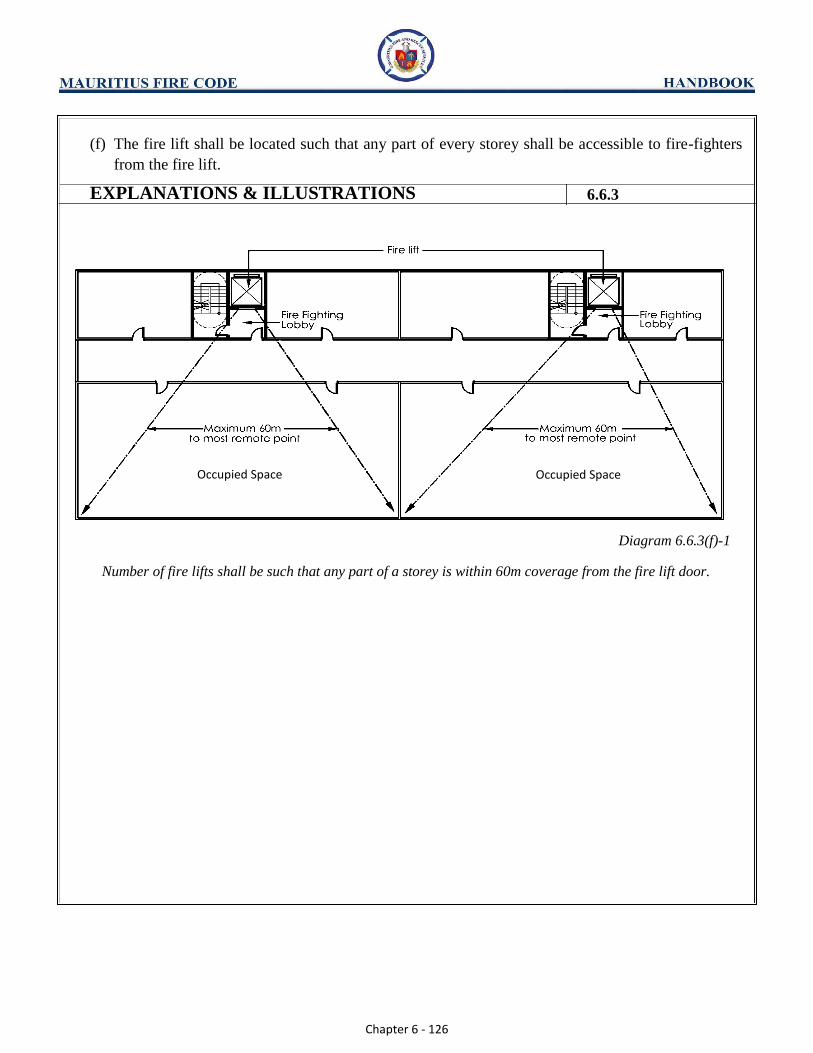
Chapter 6 - 126
(f) The fire lift shall be located such that any part of every storey shall be accessible to fire-fighters
from the fire lift.
Diagram 6.6.3(f)-1
Number of fire lifts shall be such that any part of a storey is within 60m coverage from the fire lift door.
EXPLANATIONS & ILLUSTRATIONS 6.6.3
Occupied Space Occupied Space
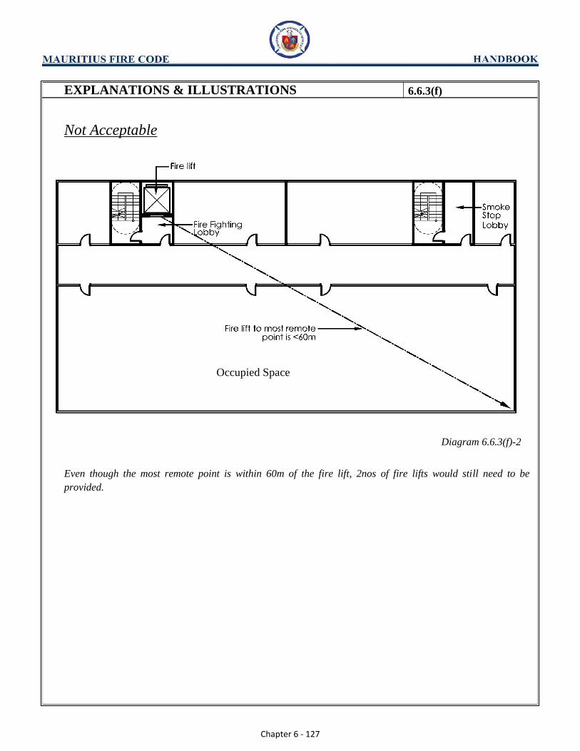
Chapter 6 - 127
EXPLANATIONS & ILLUSTRATIONS 6.6.3(f)
Not Acceptable
Occupied Space
Diagram 6.6.3(f)-2
Even though the most remote point is within 60m of the fire lift, 2nos of fire lifts would still need to be
provided.

Chapter 6 - 128
EXPLANATIONS & ILLUSTRATIONS 6.6.3(f)
Not Acceptable
Diagram 6.6.3(f)-3
There are some areas that are beyond 60m of the fire lifts, see shaded. As such, a 3rd fire lift is required.
Chapter 6 - 129
CHAPTER 6
6.6 LIFTS
6.6.4 Homing of lifts
(a) Homing of lifts for buildings which are required to be provided with fire alarm system.
In a fire emergency when any one of the fire detection devices or fire alarm systems is activated,
all the passenger lifts shall be brought to the designated floor (usually1st
storey) and park there
with the lift landing doors remaining opened.
(b) Homing of lifts for buildings which are required to have standby generating plant.
In the event of power failure or power interruption in the building, the supply to the lifts shall be
automatically switched over to the emergency power supply from the generating plant and the
lifts shall be brought to the designated floor and park there with the lift landing doors remaining
open until all the lifts have been brought down to the designated floor. Thereafter, one or more
lifts may resume operation depending on the capacity of the emergency generating plant, in
addition to the fire lift. Normal operation of the lift shall be automatically reset on the return of
normal power supply.
(c) Homing of lifts for buildings which are not required to have standby generating plant.
All passenger lifts, including hydraulic lifts, shall be provided with Automatic Rescue Device
(ARD). The ARD shall permit the lifts to move and park at the nearest lift landing floor with the
lift/landing doors in the opened position in the event of power failure. Homing any of the lifts to
a basement storey is not permitted.
(d) Homing of lifts for Mixed developments comprising residential and non-residential components
(i) All passenger lifts which serve the residential and non-residential floors shall be required to
home to the designated or alternative designated floor in the event of power failure and/or
fire. The lifts shall be provided with secondary power supplies from standby generating
plant of sufficient capacity. (ii) Where the passenger lifts serve only the residential floors and by-pass the non-residential
floors in a protected shaft, the lifts shall be required to be installed with Automatic Rescue
Device (ARD), provided the habitable height of the highest floor does not exceed 60m. (iii) Where the passenger lifts serve the upper residential floors and the basement non-residential
floor/s, including car parks, the lifts shall be provided with emergency power supply from
standby generating plant for homing to the designated floor when there is a power failure in
the building. In a fire emergency, the passenger lifts shall be brought to the designated floor
when any of the fire alarm system in the basement non-residential floor/s is activated.

Chapter 6 - 130
(e) Alternative designated floor
(i) Where the lifts open directly into an occupancy area in a designated floor, for example, a
shopping floor or an office floor, an alternative designated floor (e.g. 2nd
storey) shall also
be identified. The lifts shall be brought to the alternative floor in the event that there is a fire
in the designated floor, in close vicinity of the lift landing door. The activation of any
detector or sprinkler head covering the lift landing space at the designated floor would cause
the lift to be re-directed to home to the alternative floor. (ii) The alternative floor shall have minimum fire hazard and pre-selected for the homing of
passenger lifts, and where people can escape to safety in an exit staircase or other exit from
the lift landing door. (iii) In building under (e)(i) which are not provided with sprinkler or automatic fire alarm
system, suitable sensors shall be provided at ceiling level to cover the lift landing space. The
activation of any sensor would cause the lifts to be re-directed to home to the alternative
floor. (iv) The above requirements on homing of lifts to an alternative floor need not be applied to
standalone open-sided car park and residential buildings under Purpose Group I.
EXPLANATIONS & ILLUSTRATIONS 6.6.4
No illustration.