CHAPTER 6 Space Trusses · 2013-03-28 · INTRODUCTION •A space truss consists of members joined...
43
CHAPTER 6 Space Trusses
Transcript of CHAPTER 6 Space Trusses · 2013-03-28 · INTRODUCTION •A space truss consists of members joined...

CHAPTER 6 Space Trusses

INTRODUCTION
• A space truss consists of members joined together at their ends to form a stable three-dimensional structures
• A stable simple space truss can be built from the basic tetrahedral, formed by connecting six members with four joints

INTRODUCTION
• To determine the stability and determinacy of space trusses
• To determine member forces of space trusses using tension coefficient analysis
OBJECTIVES

1. Simple Space Truss
This truss is constructed from a tetrahedron. The truss can be enlarged by adding three members.
TYPE OF SPACE TRUSSES

2. Compound Space Truss This truss is constructed by combining two or more simple truss.
TYPE OF SPACE TRUSSES
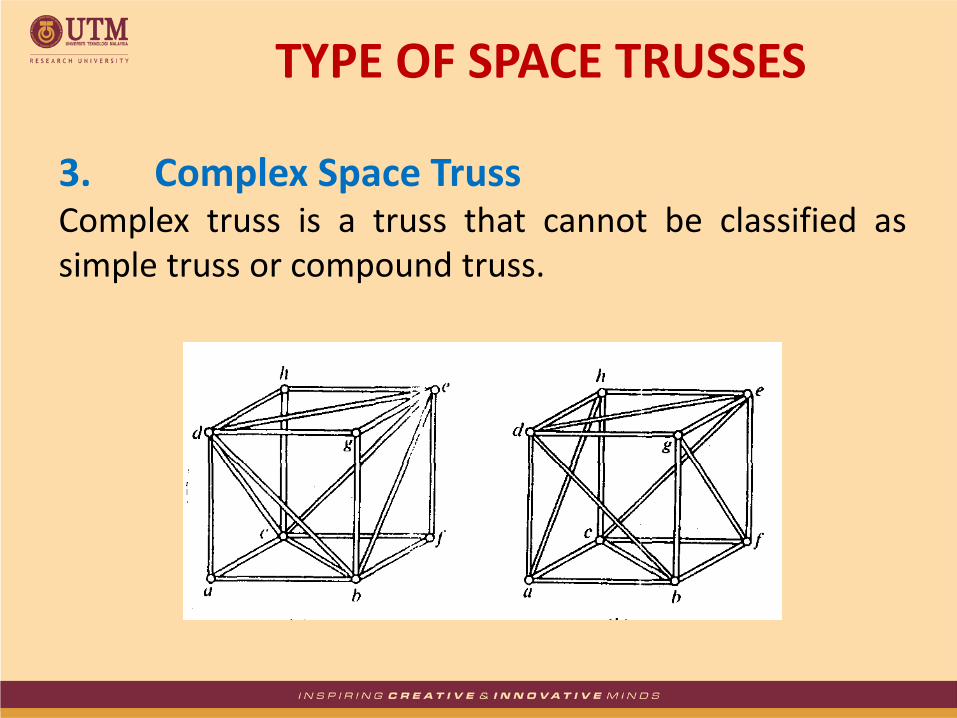
3. Complex Space Truss Complex truss is a truss that cannot be classified as simple truss or compound truss.
TYPE OF SPACE TRUSSES
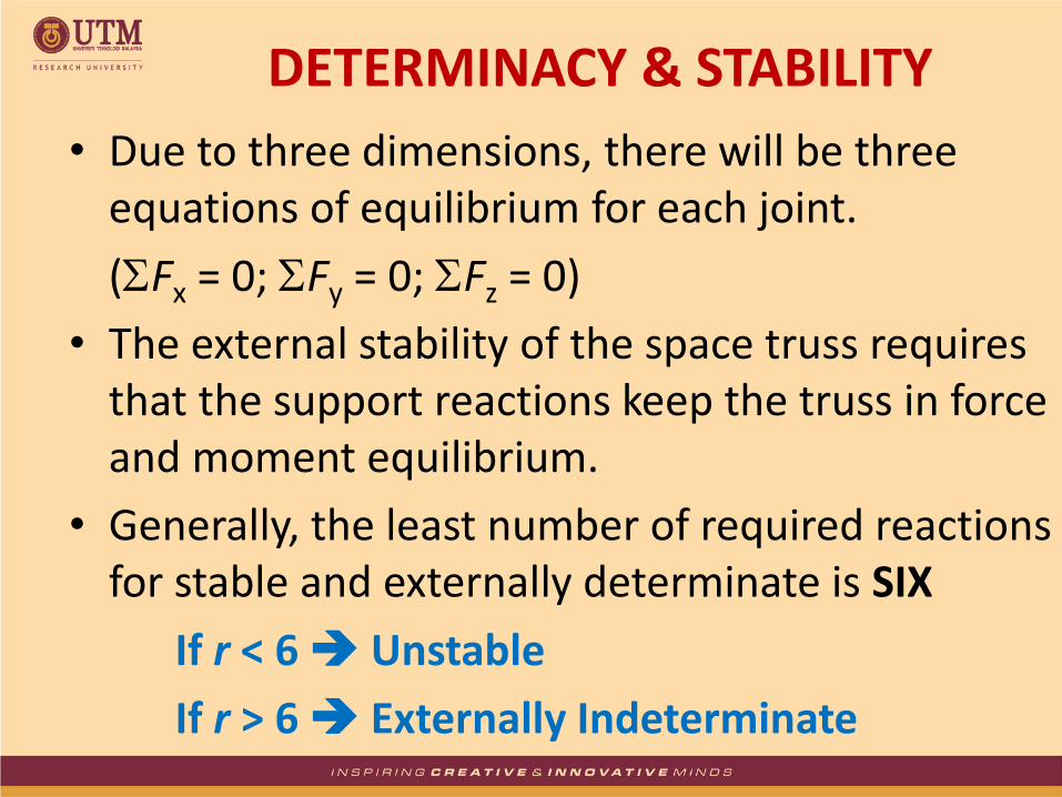
• Due to three dimensions, there will be three equations of equilibrium for each joint.
(Fx = 0; Fy = 0; Fz = 0)
• The external stability of the space truss requires that the support reactions keep the truss in force and moment equilibrium.
• Generally, the least number of required reactions for stable and externally determinate is SIX
If r < 6 Unstable
If r > 6 Externally Indeterminate
DETERMINACY & STABILITY

• For internal determinacy, if m = number of members; j = number of joints; r = number of supports; therefore:
If m = 3j + r Stable and Internally Determinate
If m < 3j + r Unstable
If m > 3j + r Internally Indeterminate
• Internal stability can sometimes be checked by careful inspection of the member arrangement.
DETERMINACY & STABILITY
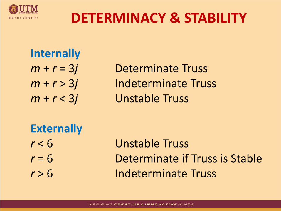
Internally m + r = 3j Determinate Truss m + r > 3j Indeterminate Truss m + r < 3j Unstable Truss Externally r < 6 Unstable Truss r = 6 Determinate if Truss is Stable r > 6 Indeterminate Truss
DETERMINACY & STABILITY

TYPES OF SUPPORT

EXAMPLE 1
Ball & Socket
m = 3, j = 4, r = 9 m + r = 12 3j = 12 m + r = 3j Determinate Truss

EXAMPLE 2
m = 15, j = 10, r = 15 m + r = 30 3j = 30 m + r = 3j Determinate Truss
Ball & Socket

EXAMPLE 3
Ball & Socket
m = 13, j = 8, r = 12 m + r = 25 3j = 24 m + r = 25 3j = 24 Indeterminate Truss in the First Degree
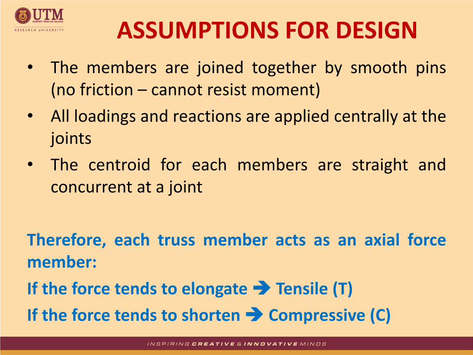
• The members are joined together by smooth pins (no friction – cannot resist moment)
• All loadings and reactions are applied centrally at the joints
• The centroid for each members are straight and concurrent at a joint
Therefore, each truss member acts as an axial force member:
If the force tends to elongate Tensile (T)
If the force tends to shorten Compressive (C)
ASSUMPTIONS FOR DESIGN
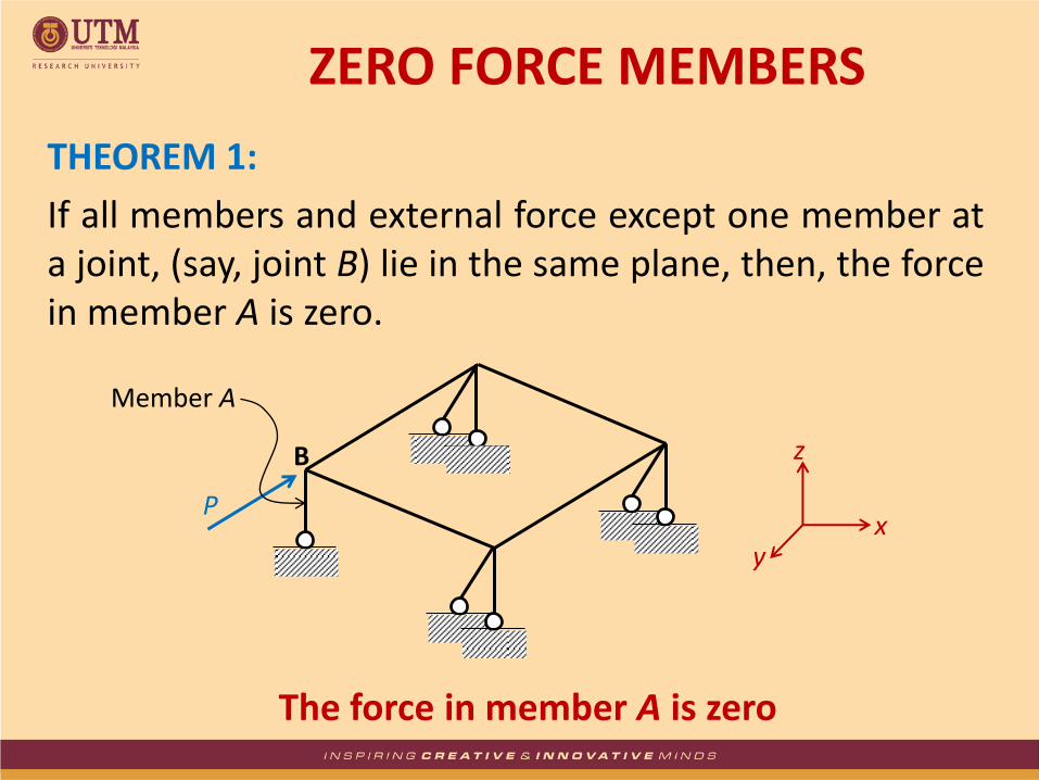
THEOREM 1:
If all members and external force except one member at a joint, (say, joint B) lie in the same plane, then, the force in member A is zero.
The force in member A is zero
ZERO FORCE MEMBERS
P
Member A
x y
z B
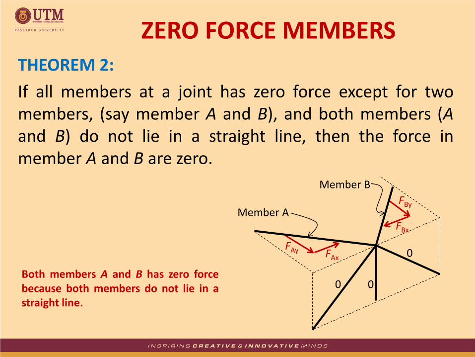
THEOREM 2:
If all members at a joint has zero force except for two members, (say member A and B), and both members (A and B) do not lie in a straight line, then the force in member A and B are zero.
Both members A and B has zero force because both members do not lie in a straight line.
ZERO FORCE MEMBERS
FAy FAx
Member A
Member B
FBx
FBy
0 0
0

If members A and B lie in a straight line, then, the forces in these members MIGHT NOT be zero. In fact, referring to the example below:
FAx = -FBx
FAy = -FBy
ZERO FORCE MEMBERS
FAy FAx
Member A
Member B
FBx FBy
0 0
0

THEOREM 3:
If three members at a joint do not lie in the same plane and there is no external force at that joint, then the force in the three members is zero.
Three members connected at a
joint has zero force. A plane can
consists of two members, say
member A and B. Thus, no force
can balance the component of
member C that is normal to the
plane.
ZERO FORCE MEMBERS
Member B
Member C
Member A
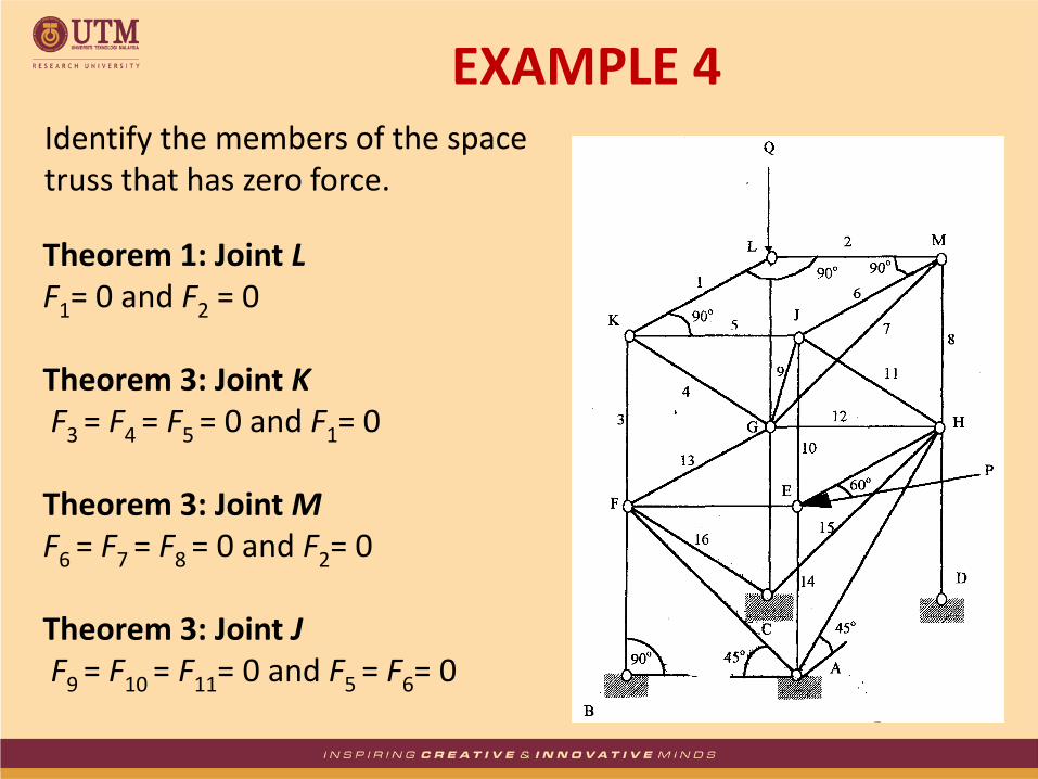
Identify the members of the space truss that has zero force.
Theorem 1: Joint L F1= 0 and F2 = 0 Theorem 3: Joint K F3 = F4 = F5 = 0 and F1= 0 Theorem 3: Joint M F6 = F7 = F8 = 0 and F2= 0 Theorem 3: Joint J F9 = F10 = F11= 0 and F5 = F6= 0
EXAMPLE 4
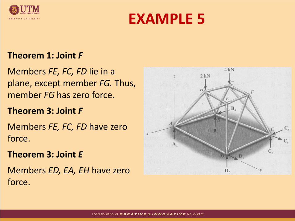
Theorem 1: Joint F
Members FE, FC, FD lie in a plane, except member FG. Thus, member FG has zero force.
Theorem 3: Joint F
Members FE, FC, FD have zero force.
Theorem 3: Joint E
Members ED, EA, EH have zero force.
EXAMPLE 5
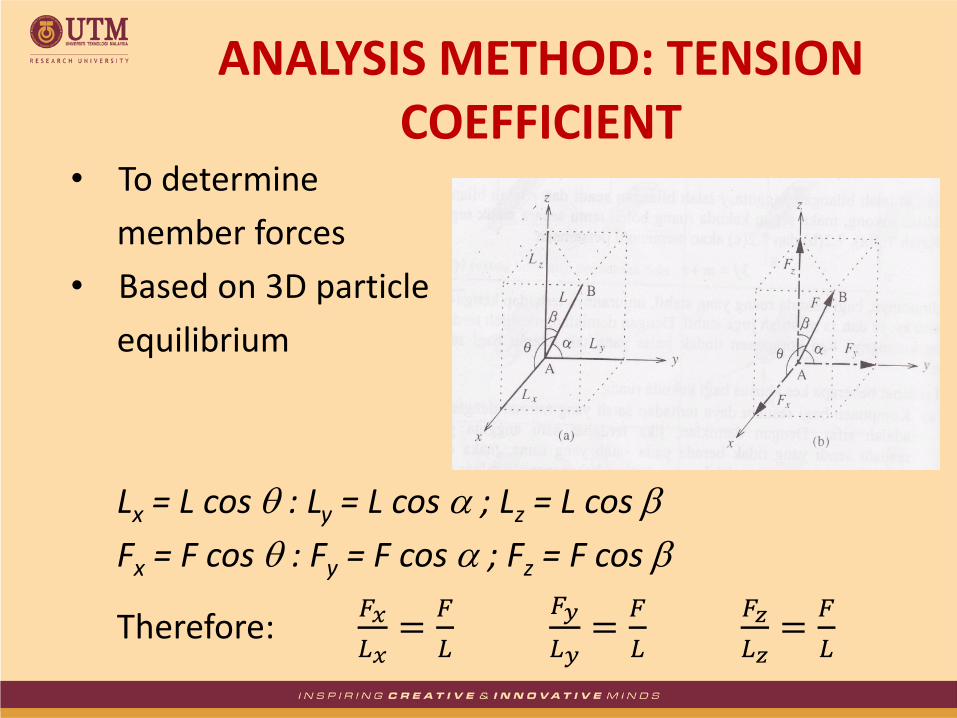
• To determine
member forces
• Based on 3D particle
equilibrium
Lx = L cos : Ly = L cos ; Lz = L cos
Fx = F cos : Fy = F cos ; Fz = F cos
Therefore: 𝐹𝑥
𝐿𝑥=
𝐹
𝐿
𝐹𝑦
𝐿𝑦=
𝐹
𝐿
𝐹𝑧
𝐿𝑧=
𝐹
𝐿
ANALYSIS METHOD: TENSION COEFFICIENT

• Tension Coefficient: t = F/L
Fx = tLx ; Fy = tLy ; Fz = tLz
• If t positive (tension), if t negative (compression)
• The actual force and length are given from:
𝐿 = 𝐿𝑥2 + 𝐿𝑦
2+ 𝐿𝑧2 𝐹 = 𝐹𝑥
2 + 𝐹𝑦2+ 𝐹𝑧
2
• For 3D equilibrium:
Fx = 0 ; Fy = 0 ; Fz = 0
tLx = 0 ; tLy = 0 ; tLz = 0
ANALYSIS METHOD: TENSION COEFFICIENT

The component of length, L, and force, F in the x, y, z direction
ANALYSIS METHOD: TENSION COEFFICIENT
y
x
z
Ly , Fy
Lz , Fz
A
L, F
Lx , Fx

Where t = F/L
t = tension coefficient
ANALYSIS METHOD: TENSION COEFFICIENT
𝐹𝑥 = 𝐹𝑐𝑜𝑠𝜃𝑥
𝐹𝑥 = 𝐹𝐿𝑥
𝐿=
𝐹
𝐿𝐿𝑥
𝐹𝑥 = 𝑡 ∙ 𝐿𝑥
y
x
z
Fx
Fy
Fz
C E
D
A
B
O
F
X
ANALYSIS METHOD: TENSION COEFFICIENT
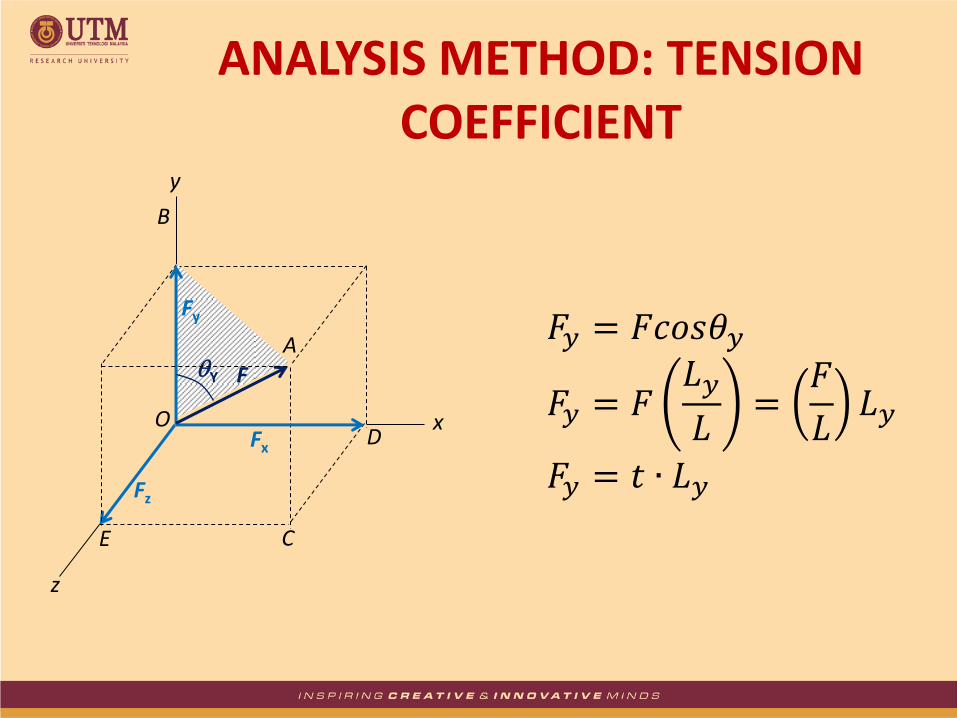
𝐹𝑦 = 𝐹𝑐𝑜𝑠𝜃𝑦
𝐹𝑦 = 𝐹𝐿𝑦
𝐿=
𝐹
𝐿𝐿𝑦
𝐹𝑦 = 𝑡 ∙ 𝐿𝑦
y
x
z
Fz
C E
D
B
O Fx
Fy
A Y F

ANALYSIS METHOD: TENSION COEFFICIENT
𝐹𝑧 = 𝐹𝑐𝑜𝑠𝜃𝑧
𝐹𝑧 = 𝐹𝐿𝑧
𝐿=
𝐹
𝐿𝐿𝑧
𝐹𝑧 = 𝑡 ∙ 𝐿𝑧
y
x
z
C
D
B
Fx
Fy
A
Fz
E
O
F
Z
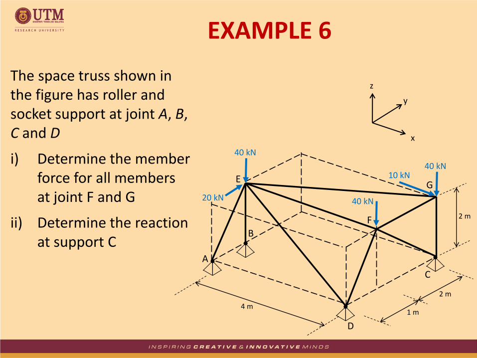
The space truss shown in the figure has roller and socket support at joint A, B, C and D
i) Determine the member force for all members at joint F and G
ii) Determine the reaction at support C
EXAMPLE 6
y
40 kN 10 kN
40 kN
20 kN
4 m 1 m
2 m
2 m
A
B
E
D
C
F
G
40 kN
x
z

1. Start at Joint G
Member Lx (m) Ly (m) Lz (m) L (m) t (kN/m) F (kN)
GC 0 0 -2 2 -20 -40 GE -4 -2 0 4.47 2.5 11.18 GF 0 -2 0 2 -2.5 -5
Force (kN) 10 0 -40
Fx = 0: -4tGE + 10 = 0 tGE= 2.5 kN/m
Fz = 0: -2tGC – 40 = 0 tGC = -20 kN/m
Fy = 0: -2tGE – 2tGF = 0
-2(2.5) – 2tGF = 0 tGF = -2.5 kN/m
EXAMPLE 6 – Solution

2. Move to Joint F
Member Lx (m) Ly (m) Lz (m) L (m) t (kN/m) F (kN)
FC 0 2 -2 2.83 -5 -14.14 FD 0 -1 -2 2.24 -15 -33.6 FE -4 0 0 4 0 0 FG 0 2 0 -2.5
Force (kN) 0 0 -40
Fx = 0: -4tFE = 0 tFE = 0 kN/m
Fy = 0: 2tFC – tFD + 2tFG = 0 2tFC – tFD – 5 = 0 ....... (i)
Fz = 0: -2tFC – 2tFD – 40 = 0 .......(ii)
(i) + (ii): -3tFD -45 = 0 tFD = -15 kN/m
From (i): -2tFC – (-15) – 5 = 0 tFC = -5 kN/m
EXAMPLE 6 – Solution
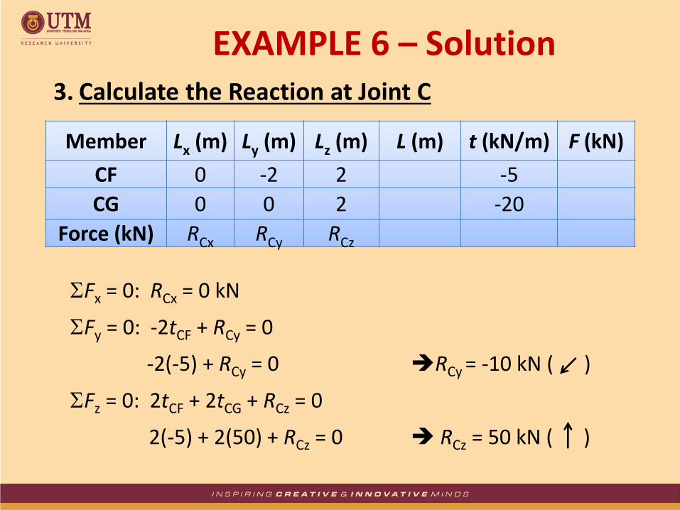
3. Calculate the Reaction at Joint C
Member Lx (m) Ly (m) Lz (m) L (m) t (kN/m) F (kN)
CF 0 -2 2 -5
CG 0 0 2 -20
Force (kN) RCx RCy RCz
Fx = 0: RCx = 0 kN
Fy = 0: -2tCF + RCy = 0
-2(-5) + RCy = 0 RCy = -10 kN ( )
Fz = 0: 2tCF + 2tCG + RCz = 0
2(-5) + 2(50) + RCz = 0 RCz = 50 kN ( )
EXAMPLE 6 – Solution
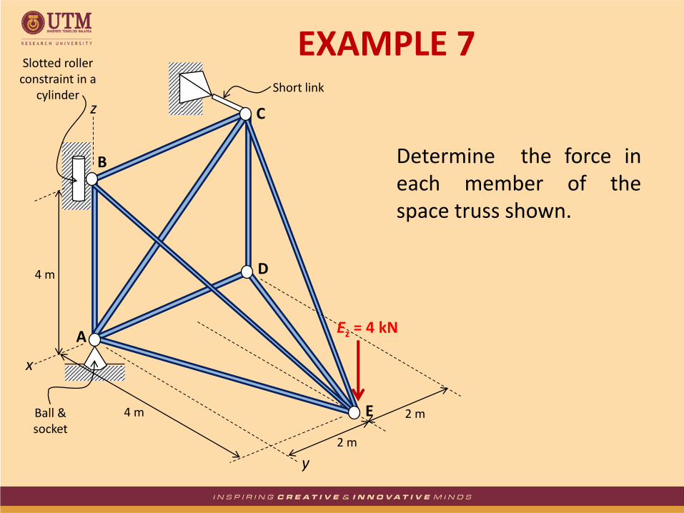
Determine the force in each member of the space truss shown.
EXAMPLE 7
4 m
x
z
4 m
2 m
2 m
y
A
C
D
E
Ez = 4 kN
B
Short link
Ball & socket
Slotted roller constraint in a
cylinder
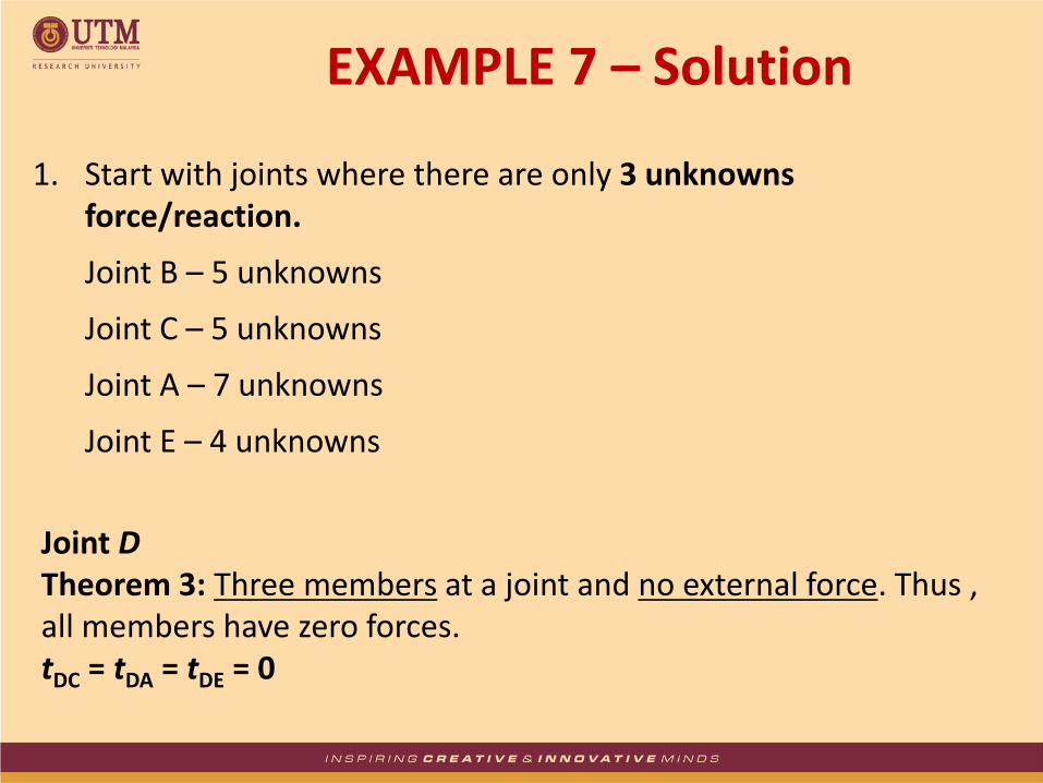
1. Start with joints where there are only 3 unknowns force/reaction.
Joint B – 5 unknowns
Joint C – 5 unknowns
Joint A – 7 unknowns
Joint E – 4 unknowns
Joint D Theorem 3: Three members at a joint and no external force. Thus , all members have zero forces. tDC = tDA = tDE = 0
EXAMPLE 7 – Solution

EXAMPLE 7 – Solution Joint E
Member Lx (m) Ly (m) Lz (m) L (m) t (kN/m) F (kN)
EC -2 -4 4 4.47 0 0 EB 2 -4 4 6 1 6 ED -2 -4 0 4.47 0 0 EA 2 -4 0 4.47 -1 -4.47
Force (kN) 0 0 -4
Fz = 0: 4tEB + 4tEC – 4 = 0 .......(i)
Fx = 0: -2tEC + 2tEB – 2tED + 2tEA = 0 ....... (ii) where tED = 0
Fy = 0: -4tEC – 4tEB – 4tED – 4tEA = 0 .......(iii) where tED = 0
Solve Eq. (i), (ii) & (iii): tEC = 0 kN/m, tEA = -1 kN/m and tEB = 1 kN/m

EXAMPLE 7 – Solution Joint C
Joint C has three (3) unknowns, as tCE = tCD = 0
Therefore, by Theorem 3:
tCB = tCA = RCy = 0
x
z
y
A
C
D
E
Ez = 4 kN
B
RCy
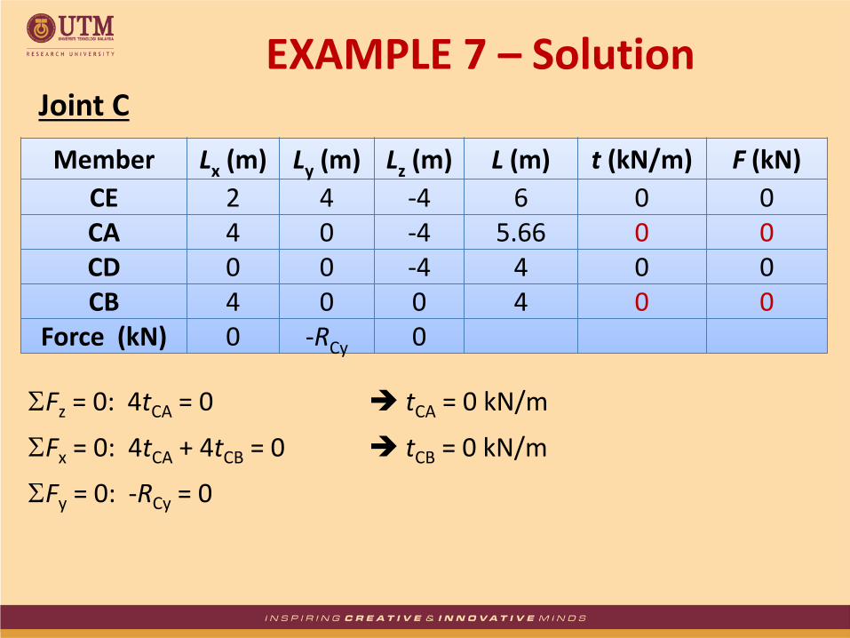
EXAMPLE 7 – Solution Joint C
Member Lx (m) Ly (m) Lz (m) L (m) t (kN/m) F (kN)
CE 2 4 -4 6 0 0 CA 4 0 -4 5.66 0 0 CD 0 0 -4 4 0 0 CB 4 0 0 4 0 0
Force (kN) 0 -RCy 0
Fz = 0: 4tCA = 0 tCA = 0 kN/m
Fx = 0: 4tCA + 4tCB = 0 tCB = 0 kN/m
Fy = 0: -RCy = 0
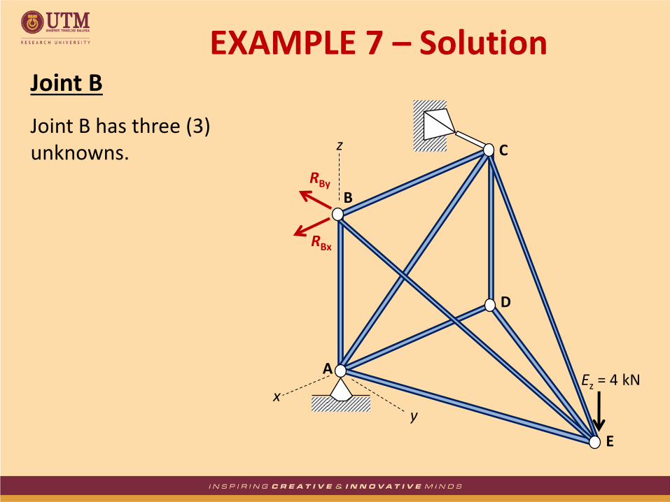
EXAMPLE 7 – Solution Joint B
Joint B has three (3) unknowns.
x
z
y
A
C
D
E
Ez = 4 kN
B RBy
RBx

EXAMPLE 7 – Solution Joint B
Member Lx (m) Ly (m) Lz (m) L (m) t (kN/m) F (kN)
BC -4 0 0 4 0 0 BA 0 0 -4 4 -1 -4 BE -2 -4 -4 6 1 6
Force (kN) RBx -RBy 0
Fx = 0: -4tBC – 2tBE + RBx = 0 RBx = 2 kN
Fy = 0: -4tBE – RBy = 0 RBy = -4 kN
Fz = 0: -4tBA – 4tBE = 0 tBA = -1 kN/m

EXAMPLE 7 – Solution Joint A
x
z
y
A
C
D
E
Ez = 4 kN
B
RAy
RAx
RAz

EXAMPLE 7 – Solution Joint A
Member Lx (m) Ly (m) Lz (m) L (m) t (kN/m) F (kN)
AB 0 0 4 4 -1 -4 AC -4 0 4 5.66 0 0 AD -4 0 0 4 0 0 AE -2 4 0 4.47 -1 -4.47
Force (kN) -RAx RAy RAz
Fx = 0: -4tAC – 4tAD – 2tAE – RAx = 0 RAx = -2 kN
Fy = 0: 4tAE + RAy = 0 RAy = -4 kN
Fz = 0: 4tAB + 4tAC + RAz = 0 RAz = 4 kN

EXAMPLE 7 – Solution Method 2
Reactions at A, B and C can also be obtained from Method 2
x
z
y
A
C
D
E
Ez = 4 kN
B
RAy
RAx
RAz
RBy
RBx
RCy

EXAMPLE 7 – Solution Method 2
My = 0
-4(2) + RBx (4) = 0
RBx = 2 kN
Mz = 0
RCy = 0 kN
Mx = 0
RBy (4) – 4(4) = 0
RBy = 4 kN
Fx = 0
2 – RAx = 0
RAx = 2 kN
Fy = 0
RAy – 4 = 0
RAy = 4 kN
Fz = 0
RAz – 4 = 0
RAz = 4 kN
A
B
C
D
x
y
z
O
2 m
3 m
7 m
2 m
1800 N
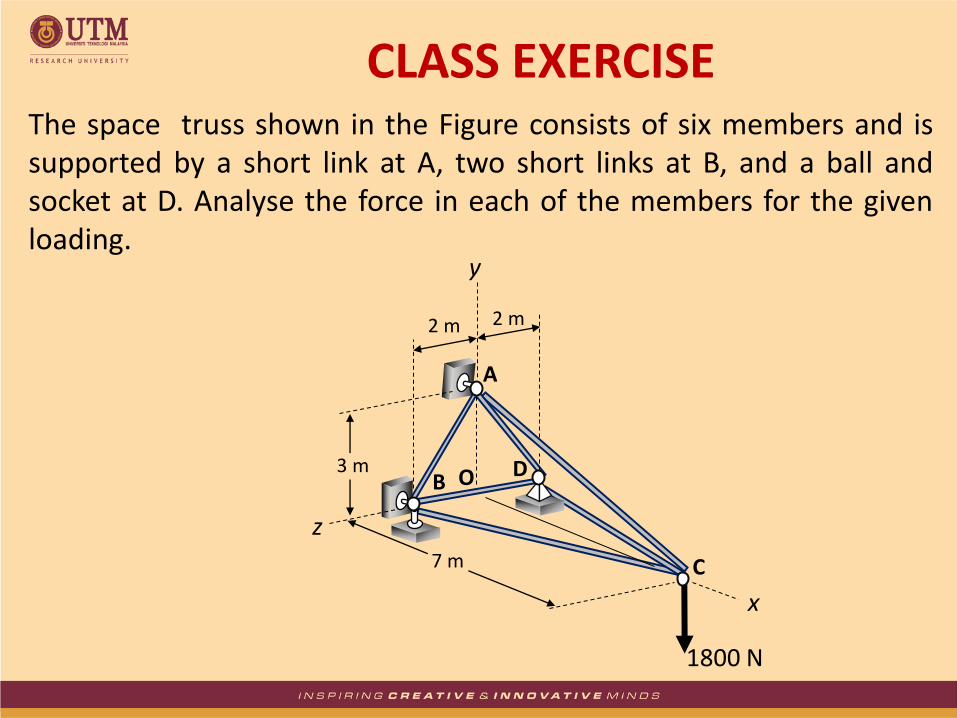
The space truss shown in the Figure consists of six members and is supported by a short link at A, two short links at B, and a ball and socket at D. Analyse the force in each of the members for the given loading.
CLASS EXERCISE