
Chapter 6 Polarization and Crystal Opticsfaculty.washington.edu/lylin/EE485W04/Ch6.pdf ·...
17
EE 485, Winter 2004, Lih Y. Lin 1 Chapter 6 Polarization and Crystal Optics - Polarization ↔ Time course of the direction of ) , ( t r * E E E E - Polarization affects: Amount of light reflected at material interfaces. Absorption in some materials. Scattering. Refractive index (thus velocity) of anisotropic materials. Optically active materials to rotate polarization. 6.1 Polarization of Light Consider ( ) { } c z t j t z − ω = ( exp Re ) , ( A E E E E (6.1-1) With complex envelope y x A ˆ ˆ y x A A + = (6.1-2) Trace the endpoint of ) , ( t z E E E E at each position z as a function of time. The polarization ellipse ) exp( , ) exp( y y y x x x j a A j a A ϕ = ϕ = y x ˆ ˆ ) , ( y x t z E E + = E E E E (6.1-3) ( ) [ ] x x x c z t a ϕ + − ω = cos E (6.1-4a) ( ) [ ] y y y c z t a ϕ + − ω = cos E (6.1-4b) ϕ = ϕ − + 2 2 2 2 2 sin cos 2 y x y x y y x x a a a a E E E E (6.1-5) → An ellipse. The shape of the ellipse depends on x y a a and ϕ . The size of the ellipse determines intensity η + = 2 2 2 y x a a I (η: impedance of the medium).
Transcript of Chapter 6 Polarization and Crystal Opticsfaculty.washington.edu/lylin/EE485W04/Ch6.pdf ·...

EE 485, Winter 2004, Lih Y. Lin
1
Chapter 6 Polarization and Crystal Optics
- Polarization ↔ Time course of the direction of ),( tr�EEEE - Polarization affects:
� Amount of light reflected at material interfaces. � Absorption in some materials. � Scattering. � Refractive index (thus velocity) of anisotropic materials. � Optically active materials to rotate polarization.
6.1 Polarization of Light Consider ( ){ }c
ztjtz −ω= (expRe),( AEEEE (6.1-1) With complex envelope yxA ˆˆ yx AA += (6.1-2) Trace the endpoint of ),( tzEEEE at each position z as a function of time. The polarization ellipse )exp( ,)exp( yyyxxx jaAjaA ϕ=ϕ= yx ˆˆ),( yxtz EE +=EEEE (6.1-3)
( )[ ]xxx czta ϕ+−ω= cosE (6.1-4a)
( )[ ]yyy czta ϕ+−ω= cosE (6.1-4b)
ϕ=ϕ−+ 22
2
2
2
sincos2yx
yx
y
y
x
x
aaaaEEEE (6.1-5)
→ An ellipse. The shape of the ellipse depends on x
ya
a and ϕ . The size
of the ellipse determines intensity η+
=2
22yx aa
I (η: impedance of the medium).
EE 485, Winter 2004, Lih Y. Lin
2
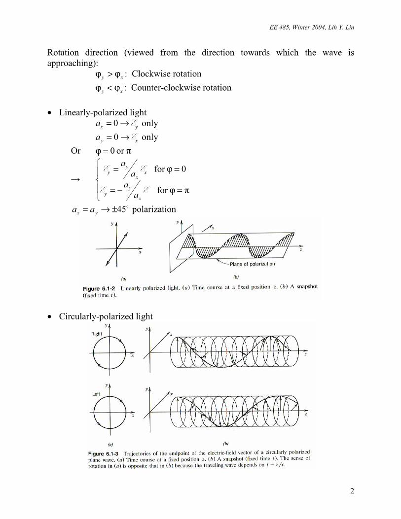
Rotation direction (viewed from the direction towards which the wave is approaching): xy ϕ>ϕ : Clockwise rotation xy ϕ<ϕ : Counter-clockwise rotation • Linearly-polarized light yxa E→= 0 only xya E→= 0 only Or π=ϕ or 0
→
π=ϕ−=
=ϕ=
for
0for
EE
EE
x
yy
xx
yy
aa
aa
�45±→= yx aa polarization
• Circularly-polarized light
EE 485, Winter 2004, Lih Y. Lin
3
0aaa yx ==
2π=ϕ → Right circularly-polarized
2π−=ϕ → Left circularly-polarized
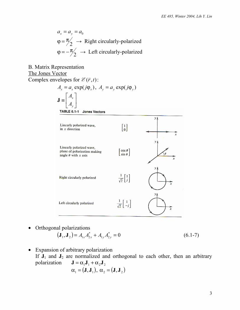
B. Matrix Representation The Jones Vector Complex envelopes for ),( tr�EEEE : )exp( xxx jaA ϕ= , )exp( yyy jaA ϕ=
≡
y
x
AA
J
• Orthogonal polarizations ( ) 0, *
21*2121 =+= yyxx AAAAJJ (6.1-7)
• Expansion of arbitrary polarization
If J1 and J2 are normalized and orthogonal to each other, then an arbitrary polarization 2211 JJJ α+α= ( )11 , JJ=α , ( )22 , JJ=α
EE 485, Winter 2004, Lih Y. Lin
4
Example:
−+
=
jj1
211
21
01
Matrix representation of polarization devices
Input:
y
x
AA
1
1 , Output:
y
x
AA
2
2
≡
=
y
x
y
x
y
x
AA
AA
TTTT
AA
1
1
1
1
2221
1211
2
2 T (6.1-9)
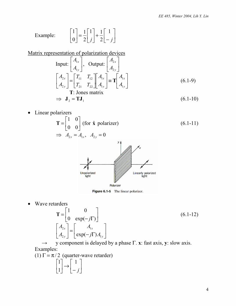
T: Jones matrix 12 TJJ =⇒ (6.1-10) • Linear polarizers
=
0001
T (for x polarizer) (6.1-11)
0 , 212 ==⇒ yxx AAA
• Wave retarders
Γ−=
)exp(001
jT (6.1-12)
Γ−=
y
x
y
x
AjA
AA
1
1
2
2
)exp(
→ y component is delayed by a phase Γ. x: fast axis, y: slow axis. Examples: (1) 2/π=Γ (quarter-wave retarder)
−→
j1
11

EE 485, Winter 2004, Lih Y. Lin
5
→
111
j
(2) π=Γ (half-wave retarder)
−→
11
11
−→
jj11
• Polarization rotators
θθθ−θ
=cossinsincos
T (6.1-13)
θ+θθ+θ
→
θθ
)sin()cos(
sincos
1
1
1
1
• Cascaded polarization devices
12... TTTT ⋅⋅⋅= M
Coordinate transformation JRJ )(' θ= (6.1-14)
θθ−θθ
=θcossinsincos
)(R (6.1-15)
)()(' θ−θ= TRRT (6.1-16)

EE 485, Winter 2004, Lih Y. Lin
6
)(')( θθ−= RTRT (6.1-17) Normal modes (of a polarization system) States of polarization that are not changed when the wave is transmitted through the optical system. JTJ µ= (6.1-19) µ: eigenvalue J: eigenvector If T is Hermitian, i.e., T12 = T21*, the normal modes are orthogonal to each other, and can be used as an expansion basis. The response to the system can be evaluated more easily if the input wave is decomposed into the two normal modes: 2211 JJJ α+α= 2221112211 )( JJJJTTJ µα+µα=α+α= Examples (Exercise 6.1-4): (a) The normal modes of the linear polarizer are linearly polarized waves. (b) The normal modes of the wave retarder are linearly polarized waves. (c) The normal modes of the polarization rotator are right and left circularly
polarized waves. 6.2 Reflection and Refraction
=
=
=
y
x
y
x
y
x
EE
EE
EE
3
33
2
22
1
11 , , JJJ
ttJJ ,12 = : 2×2 Jones matrix for transmission r rJJ ,13 = : 2×2 Jones matrix for reflection
=
=
y
x
y
x
rr
tt
00
,0
0rt
EE 485, Winter 2004, Lih Y. Lin
7
yyyxxx EtEEtE 1212 , == (6.2-2)
yyyxxx ErEErE 1313 , == (6.2-3) For transverse electric (TE) polarization, yHxE �HE == ,ˆ
2211
2211
coscoscoscos
θ+θθ−θ=
nnnnrx (6.2-4)
xx rt +=1 (6.2-5) For transverse magnetic (TM) polarization, xHyE ˆ , HE == �
2112
2112
coscoscoscos
θ+θθ−θ=
nnnnry (6.2-6)
)1(2
1yy r
nnt += (6.2-7)
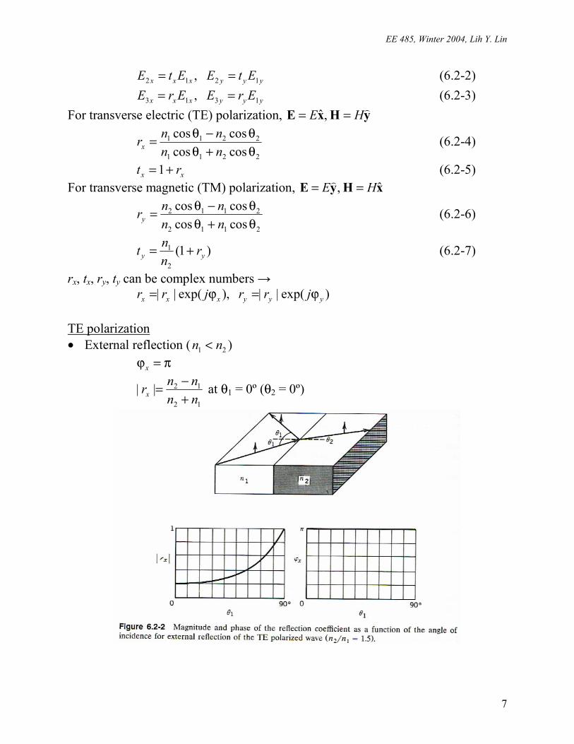
rx, tx, ry, ty can be complex numbers → )exp(|| ,)exp(|| yyyxxx jrrjrr ϕ=ϕ= TE polarization • External reflection ( 21 nn < )
π=ϕx
12
12||nnnnrx +
−= at θ1 = 0º (θ2 = 0º)
EE 485, Winter 2004, Lih Y. Lin
8
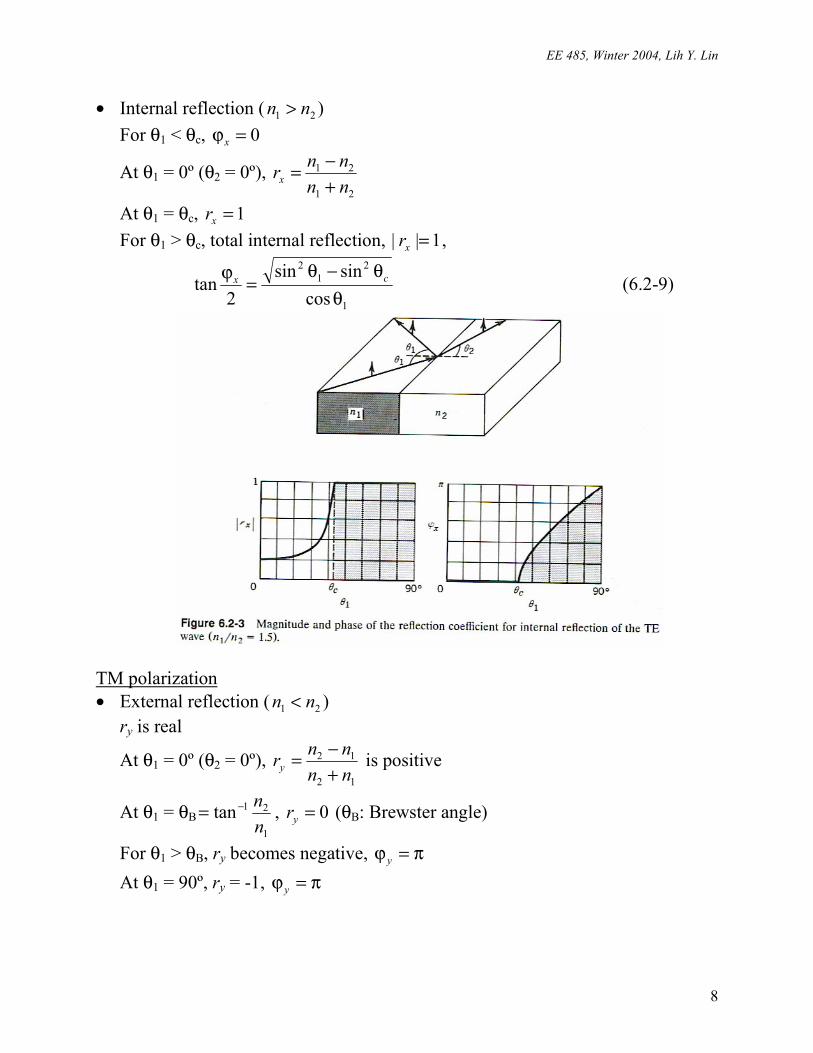
• Internal reflection ( 21 nn > ) For θ1 < θc, 0=ϕx
At θ1 = 0º (θ2 = 0º), 21
21
nnnnrx +
−=
At θ1 = θc, 1=xr For θ1 > θc, total internal reflection, 1|| =xr ,
1
21
2
cossinsin
2tan
θθ−θ
=ϕ cx (6.2-9)
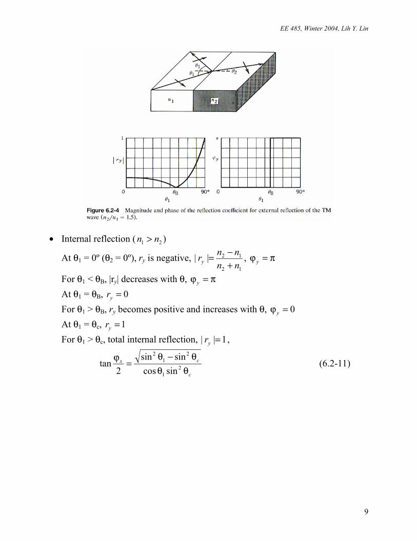
TM polarization • External reflection ( 21 nn < )
ry is real
At θ1 = 0º (θ2 = 0º), 12
12
nnnnry +
−= is positive
At θ1 = θB1
21tannn−= , 0=yr (θB: Brewster angle)
For θ1 > θB, ry becomes negative, π=ϕ y At θ1 = 90º, ry = -1, π=ϕ y
EE 485, Winter 2004, Lih Y. Lin
9
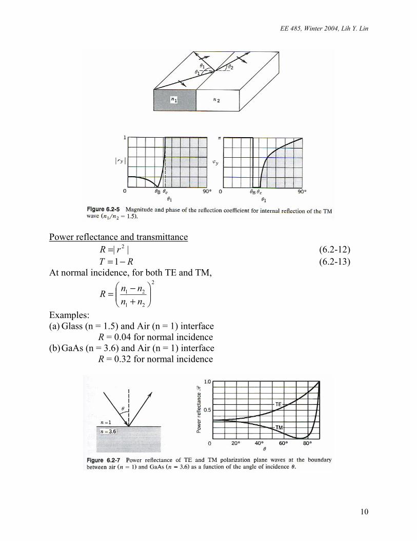
• Internal reflection ( 21 nn > )
At θ1 = 0º (θ2 = 0º), ry is negative, 12
12||nnnnry +
−= , π=ϕ y
For θ1 < θB, |ry| decreases with θ, π=ϕ y At θ1 = θB, 0=yr For θ1 > θB, ry becomes positive and increases with θ, 0=ϕ y At θ1 = θc, 1=yr For θ1 > θc, total internal reflection, 1|| =yr ,
c
cx
θθθ−θ
=ϕ2
1
21
2
sincossinsin
2tan (6.2-11)
EE 485, Winter 2004, Lih Y. Lin
10
Power reflectance and transmittance || 2rR = (6.2-12) RT −=1 (6.2-13) At normal incidence, for both TE and TM,
2
21
21
+−=
nnnnR
Examples: (a) Glass (n = 1.5) and Air (n = 1) interface R = 0.04 for normal incidence (b) GaAs (n = 3.6) and Air (n = 1) interface R = 0.32 for normal incidence
EE 485, Winter 2004, Lih Y. Lin
11
6.3 Optics of Anisotropic Media A. Refractive Indices Permittivity tensor ∑ε=
jjiji ED , i, j = 1, 2, 3 (6.3-1)
{ } ε≡εij : Electric permittivity tensor (3 × 3) εED = εεεε is symmetrical, jiij ε=ε → only 6 independent numbers. Principal axes and principal refractive indices Choose a coordinate system such that
εε
ε=
3
2
1
000000
ε
333222111 , , EDEDED ε=ε=ε= (6.3-2) → This coordinate system defines the “principal axes” of the crystal. Principal refractive indices:
0
33
0
22
0
11 , ,
εε=
εε=
εε= nnn (6.3-3)
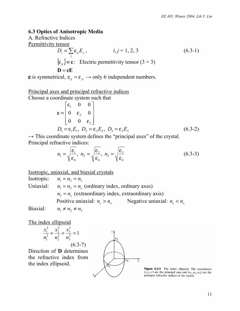
Isotropic, uniaxial, and biaxial crystals Isotropic: 321 nnn == Uniaxial: onnn == 21 (ordinary index, ordinary axes) enn =3 (extraordinary index, extraordinary axis) Positive uniaxial: oe nn > Negative uniaxial: oe nn < Biaxial: 321 nnn ≠≠ The index ellipsoid
123
23
22
22
21
21 =++
nx
nx
nx
(6.3-7) Direction of D determines the refractive index from the index ellipsoid.
EE 485, Winter 2004, Lih Y. Lin
12
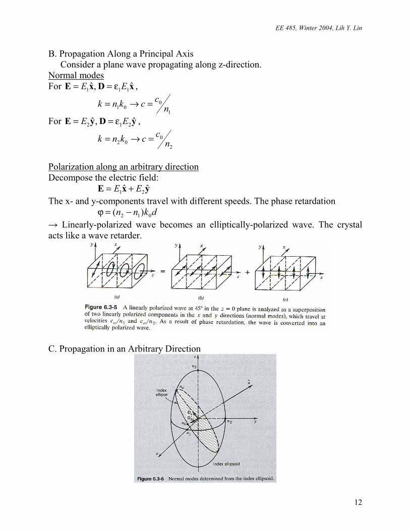
B. Propagation Along a Principal Axis Consider a plane wave propagating along z-direction.
Normal modes For xDxE ˆ ,ˆ 111 EE ε== ,
1
001 n
ccknk =→=
For yDyE ˆ ,ˆ 212 EE ε== ,
2
002 n
ccknk =→=
Polarization along an arbitrary direction Decompose the electric field: yxE ˆˆ 21 EE += The x- and y-components travel with different speeds. The phase retardation dknn 012 )( −=ϕ → Linearly-polarized wave becomes an elliptically-polarized wave. The crystal acts like a wave retarder.
C. Propagation in an Arbitrary Direction

EE 485, Winter 2004, Lih Y. Lin
13
Determine the polarizations and refractive indices an and bn of the normal modes of a wave traveling in u direction. (1) Draw a plane passing thru the origin of the index ellipsoid, normal to u . The
intersection of the plane with the ellipsoid is an ellipse, called the index ellipse.
(2) The half-width of the major and minor axes of the index ellipse are the refractive indices an and bn of the two normal modes.
(3) The directions of the major and minor axes of the index ellipse are the directions of the vectors aD and bD for the normal modes. These directions are orthogonal.
(4) The vectors aE and bE may be determined from aD and bD by εED = . DHk ω−=× (6.3-8) HEk 0ωµ=× (6.3-9)
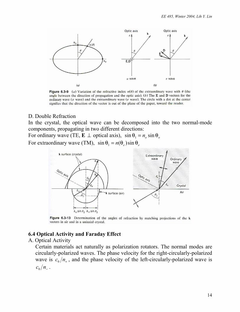
Example: Uniaxial crystal For a wave traveling at an angle θ with the optical axis (z-axis), the index ellipse has half-length on and )(θn .
2
2
2
2
2
sincos)(
1
eo nnnθ+θ=
θ (6.3-15)
The normal modes have refractive indices oa nn = for ordinary wave, and )(θ= nnb for extraordinary wave. onn =θ)( when θ = 0º, and enn =θ)( when θ =
90º. For ordinary wave, D is along the principal axis, D and E are parallel. D is perpendicular to k and z . For extraordinary wave, D and E are not parallel (unless D is along z ). D is in the k-z plane.
EE 485, Winter 2004, Lih Y. Lin
14
D. Double Refraction In the crystal, the optical wave can be decomposed into the two normal-mode components, propagating in two different directions: For ordinary wave (TE, E ⊥ optical axis), oon θ=θ sinsin 1 For extraordinary wave (TM), een θθ=θ sin)(sin 1
6.4 Optical Activity and Faraday Effect A. Optical Activity
Certain materials act naturally as polarization rotators. The normal modes are circularly-polarized waves. The phase velocity for the right-circularly-polarized wave is +nc0 , and the phase velocity of the left-circularly-polarized wave is
−nc0 .
EE 485, Winter 2004, Lih Y. Lin
15
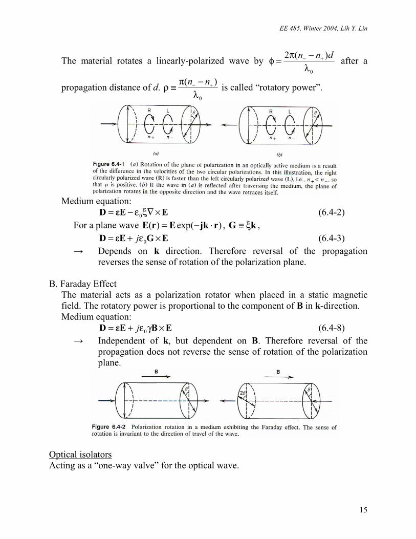
The material rotates a linearly-polarized wave by 0
)(2λ−π=φ +− dnn after a
propagation distance of d. 0
)(λ−π≡ρ +− nn is called “rotatory power”.
Medium equation: EεED ×∇ξε−= 0 (6.4-2) For a plane wave )(exp)( rjkErE ⋅−= , kG ξ≡ , EGεED ×ε+= 0j (6.4-3) → Depends on k direction. Therefore reversal of the propagation
reverses the sense of rotation of the polarization plane.
B. Faraday Effect The material acts as a polarization rotator when placed in a static magnetic field. The rotatory power is proportional to the component of B in k-direction. Medium equation: EBεED ×γε+= 0j (6.4-8) → Independent of k, but dependent on B. Therefore reversal of the
propagation does not reverse the sense of rotation of the polarization plane.
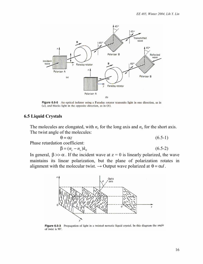
Optical isolators Acting as a “one-way valve” for the optical wave.
EE 485, Winter 2004, Lih Y. Lin
16
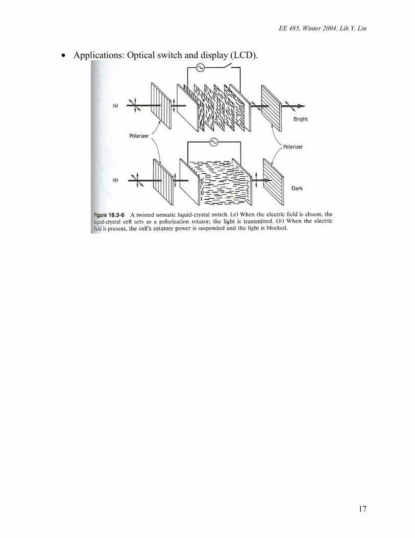
6.5 Liquid Crystals The molecules are elongated, with ne for the long axis and no for the short axis. The twist angle of the molecules: zα=θ (6.5-1) Phase retardation coefficient: 0)( knn oe −=β (6.5-2) In general, α>>β . If the incident wave at z = 0 is linearly polarized, the wave maintains its linear polarization, but the plane of polarization rotates in alignment with the molecular twist. → Output wave polarized at dα=θ .
EE 485, Winter 2004, Lih Y. Lin
17
• Applications: Optical switch and display (LCD).


