
Chapter 6 Passband Data Transmission
50
1 Chapter 6 Passband Data Transmission Passband Data Transmission concerns the Transmission of the Digital Data over the real Passband channel. © Po-Ning [email protected] Chapter 6-2 6.1 Introduction – Categories of digital communications (ASK/PSK/FSK) o Three basic signaling schemes in digital communications Amplitude-shift keying (ASK) Phase-shift keying (PSK) Frequency-shift keying (FSK)
Transcript of Chapter 6 Passband Data Transmission
1
Chapter 6 Passband Data Transmission
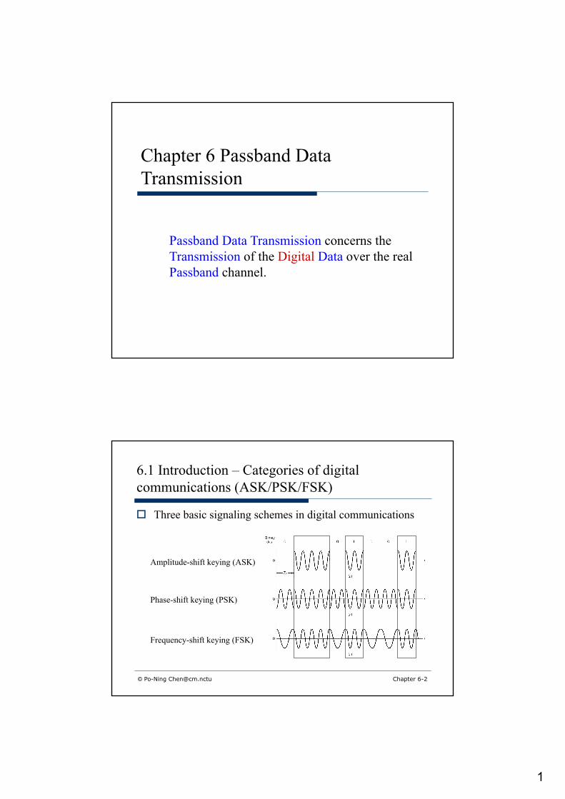
Passband Data Transmission concerns the Transmission of the Digital Data over the real Passband channel.
© Po-Ning [email protected] Chapter 6-2
6.1 Introduction – Categories of digital communications (ASK/PSK/FSK)
o Three basic signaling schemes in digital communications
Amplitude-shift keying (ASK)
Phase-shift keying (PSK)
Frequency-shift keying (FSK)

2
© Po-Ning [email protected] Chapter 6-3
Tb
0 0 1 1 0 0 0 1 1 0
4-ary Amplitude-shift keying (ASK)
4-ary Phase-shift keying (PSK)
4-ary Frequency-shift keying (FSK)
o Three basic signaling schemes in M-ary digital communications
6.1 Introduction – Categories of M-ary digital communications (ASK/PSK/FSK)
T
© Po-Ning [email protected] Chapter 6-4
6.1 Introduction – Categories of M-ary digital communications (Constant Envelope versus Non-Constant Envelope)
o Constant envelope: A necessity for non-linear channels
Non-constant envelope (ASK)
Constant envelope (PSK)
Constant evnelope (FSK)
0 0 1 1 0 0 0 1 1 0
Tb
T

3
© Po-Ning [email protected] Chapter 6-5
6.1 Introduction – Categories of digital communications (Coherent versus Non-Coherent)
o Coherent techniquen The transmitter and receiver are required to be
synchronized in both carrier phase and bit timing.o Non-Coherent technique
n The transmitter and receiver are not required to be synchronized in both carrier phase and bit timing.
© Po-Ning [email protected] Chapter 6-6
6.1 Introduction – Roadmap
o In this chapter, we will focus onn Power : A resource in communication
o Power Spectran The relation between passband signal and
baseband signal is easier to identify in spectra view
n Bandwidth: Another resource in communicationo Bandwidth efficiency : The ratio of data rate in bits
per second to the effectively utilized bandwidth. (Bits/Second/Hz)
n Probability of M-ary symbol error (Union bound)

4
© Po-Ning [email protected] Chapter 6-7
6.1 Introduction – Relation between passband and baseband signals
o Math relation between passband and baseband signals (spectrum view)
© Po-Ning [email protected] Chapter 6-8
6.1 Introduction – Relation between passband and baseband signals

5
© Po-Ning [email protected] Chapter 6-9
6.1 Introduction – Relation between passband and baseband signals
Signal Spectrum
© Po-Ning [email protected] Chapter 6-10
6.1 Introduction – Relation between passband and baseband signals
o Math relation between passband and baseband signals (power spectrum view subject to wise-sense stationarity)

6
© Po-Ning [email protected] Chapter 6-11
6.1 Introduction – Relation between passband and baseband signals
o Let
o
© Po-Ning [email protected] Chapter 6-12
6.1 Introduction – Relation between passband and baseband signals

7
© Po-Ning [email protected] Chapter 6-13
6.1 Introduction – Relation between passband signal and baseband signal
© Po-Ning [email protected] Chapter 6-14
6.1 Introduction – Relation between passband signal and baseband signal

8
© Po-Ning [email protected] Chapter 6-15
6.1 Introduction – Relation between passband signal and baseband signal
Power Spectral Density
© Po-Ning [email protected] Chapter 6-16
6.1 Introduction – Relation between passband signal and baseband signal
o Integration of the Power Spectral Density gives the Power.n Integration of the Prabability Density gives the
Prabability.

9
© Po-Ning [email protected] Chapter 6-17
6.2 Passband transmission model – Message source
© Po-Ning [email protected] Chapter 6-18
6.2 Passband transmission model – Signal space analysis
2-dimensional vector codeword (N=2) N-dimensional vector codeword
Recall Chapter 5: Signal Space Analysis

10
© Po-Ning [email protected] Chapter 6-19
6.2 Passband transmission model – Signal space analysis
Recall Chapter 5: Signal Space Analysis
© Po-Ning [email protected] Chapter 6-20
6.2 Passband transmission model – Signal space analysis
o
n What is an energy signal?

11
© Po-Ning [email protected] Chapter 6-21
6.2 Passband transmission model – Signal space analysis
© Po-Ning [email protected] Chapter 6-22
6.2 Passband transmission model – Signal space analysis
o

12
© Po-Ning [email protected] Chapter 6-23
6.2 Passband transmission model – Signal space analysis
o
© Po-Ning [email protected] Chapter 6-24
6.2 Passband transmission model –Communication channel
o Communication channeln Linear: Principle of superposition
n Sufficient bandwidth
n AWGN

13
© Po-Ning [email protected] Chapter 6-25
6.2 Passband transmission model – Signal space analysis
o Detector
© Po-Ning [email protected] Chapter 6-26
6.2 Passband transmission model – Decoder
o Signal transmission decoder
14
© Po-Ning [email protected] Chapter 6-27
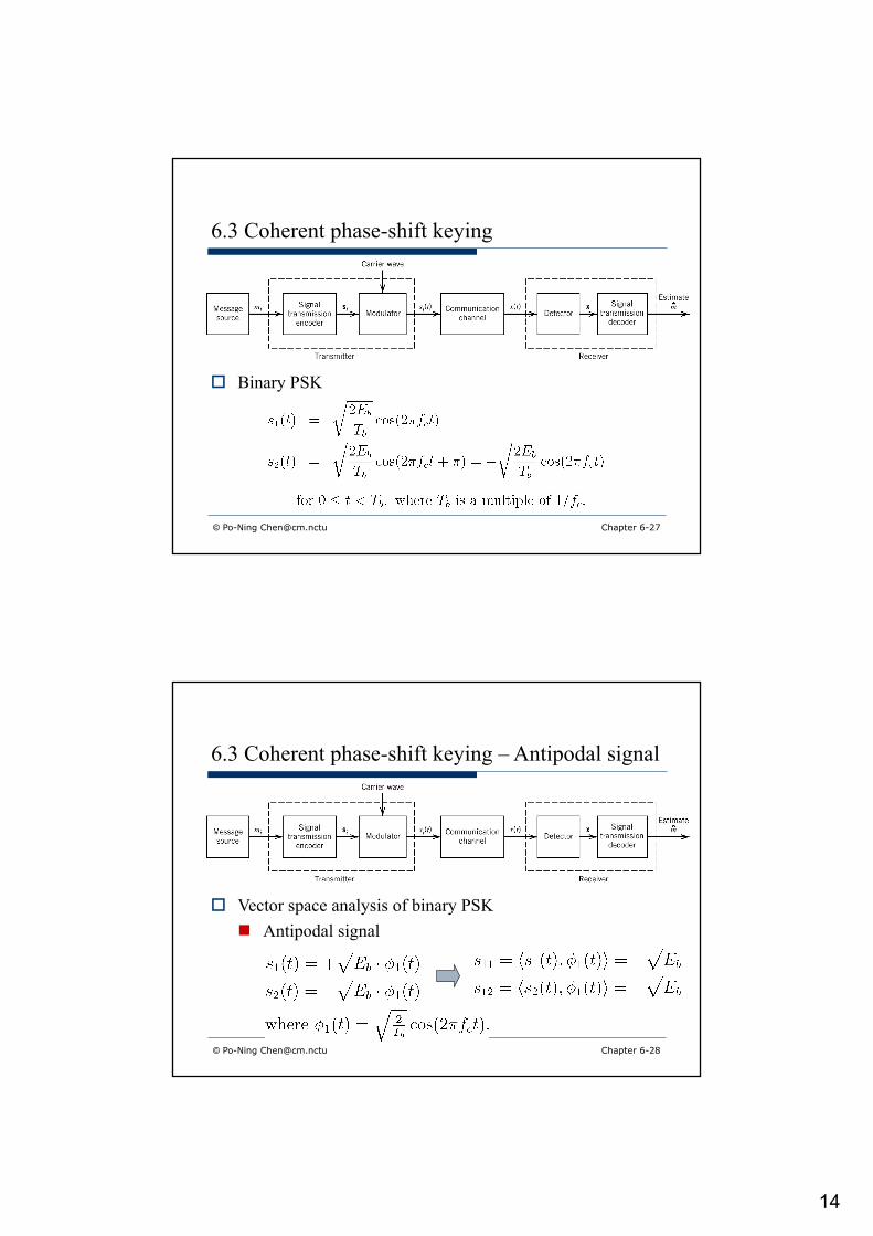
6.3 Coherent phase-shift keying
o Binary PSK
© Po-Ning [email protected] Chapter 6-28
6.3 Coherent phase-shift keying – Antipodal signal
o Vector space analysis of binary PSKn Antipodal signal
15
© Po-Ning [email protected] Chapter 6-29
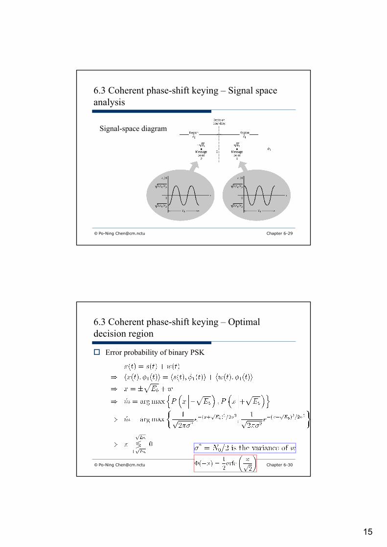
6.3 Coherent phase-shift keying – Signal space analysis
Signal-space diagram
© Po-Ning [email protected] Chapter 6-30
6.3 Coherent phase-shift keying – Optimal decision region
o Error probability of binary PSK

16
© Po-Ning [email protected] Chapter 6-31
Recall:
© Po-Ning [email protected] Chapter 6-32
6.3 Coherent phase-shift keying – Error probability
o Error probability of binary PSKn Based on the decision rule

17
© Po-Ning [email protected] Chapter 6-33
6.3 Coherent phase-shift keying – Block diagram
o Block diagram for PSK transmitter and (coherent) receiver
(coherent)
© Po-Ning [email protected] Chapter 6-34
6.3 Coherent phase-shift keying – Baseband signal
o (Complex) Baseband signal of binary PSK passband signal

18
© Po-Ning [email protected] Chapter 6-35
6.3 Coherent phase-shift keying – Sequential baseband signal
o Sequence of complex baseband signalsn No autocorrelation function for one-shot single random
variablen Calculation of autocorrelation function requires a
random process.
© Po-Ning [email protected] Chapter 6-36
6.3 Coherent phase-shift keying – Autocorrelation function

19
© Po-Ning [email protected] Chapter 6-37
© Po-Ning [email protected] Chapter 6-38
6.3 Coherent phase-shift keying – Autocorrelation function
o Power spectrum of binary PSK
20
© Po-Ning [email protected] Chapter 6-39
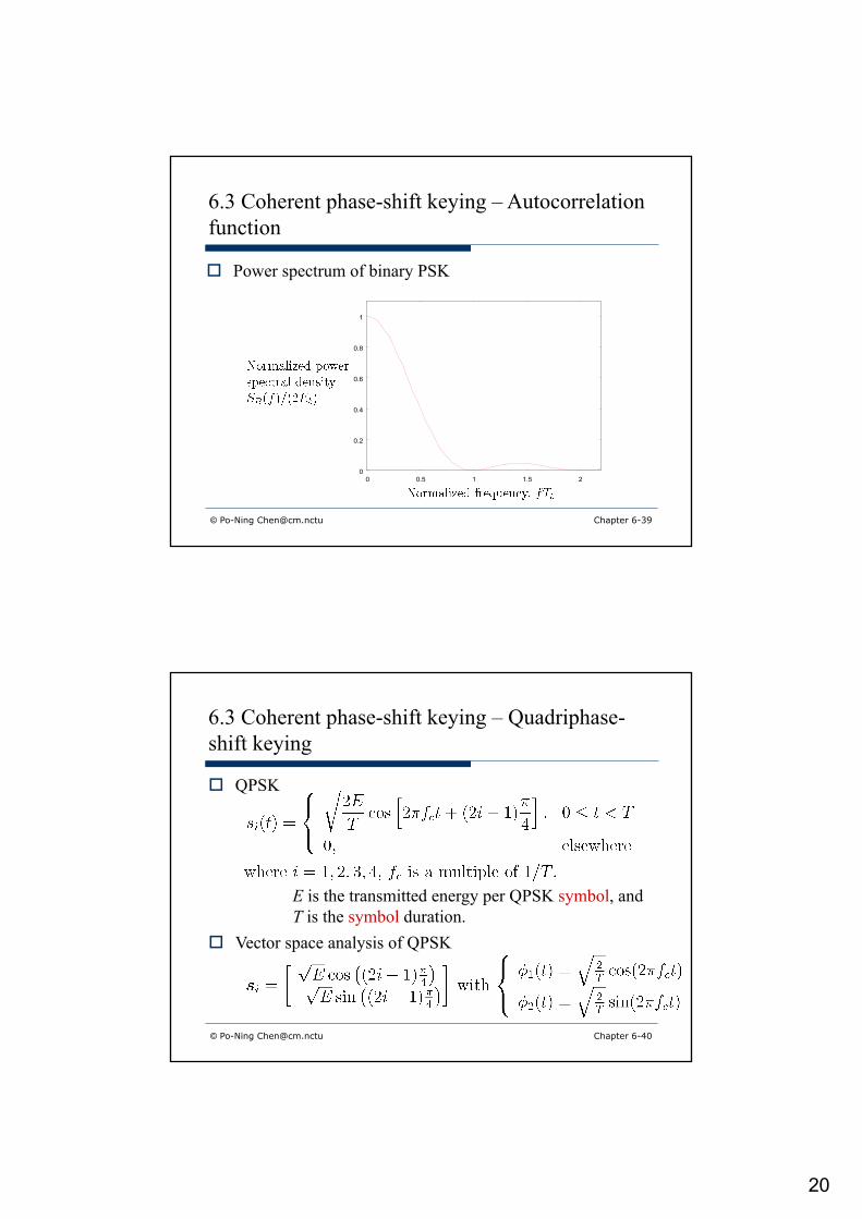
6.3 Coherent phase-shift keying – Autocorrelation function
o Power spectrum of binary PSK
0
0.2
0.4
0.6
0.8
1
0 0.5 1 1.5 2
© Po-Ning [email protected] Chapter 6-40
6.3 Coherent phase-shift keying – Quadriphase-shift keying
E is the transmitted energy per QPSK symbol, andT is the symbol duration.
o Vector space analysis of QPSK
o QPSK
21
© Po-Ning [email protected] Chapter 6-41
6.3 Coherent phase-shift keying – Quadriphase-shift keying
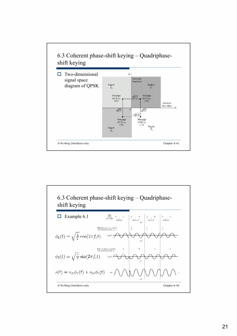
o Two-dimensional signal space diagram of QPSK
© Po-Ning [email protected] Chapter 6-42
6.3 Coherent phase-shift keying – Quadriphase-shift keying
o Example 6.1

22
o Error probability of QPSK
© Po-Ning [email protected] Chapter 6-43
© Po-Ning [email protected] Chapter 6-44
6.3 Coherent phase-shift keying – Error probability of QPSK
o Following the same derivation as that in Slide 6-32

23
© Po-Ning [email protected] Chapter 6-45
6.3 Coherent phase-shift keying – Error probability of QPSK
o Symbol error rate of QPSK
© Po-Ning [email protected] Chapter 6-46
6.3 Coherent phase-shift keying – Error probability of QPSK
o Alternative approach to derive the symbol error rate of QPSK
24
© Po-Ning [email protected] Chapter 6-47
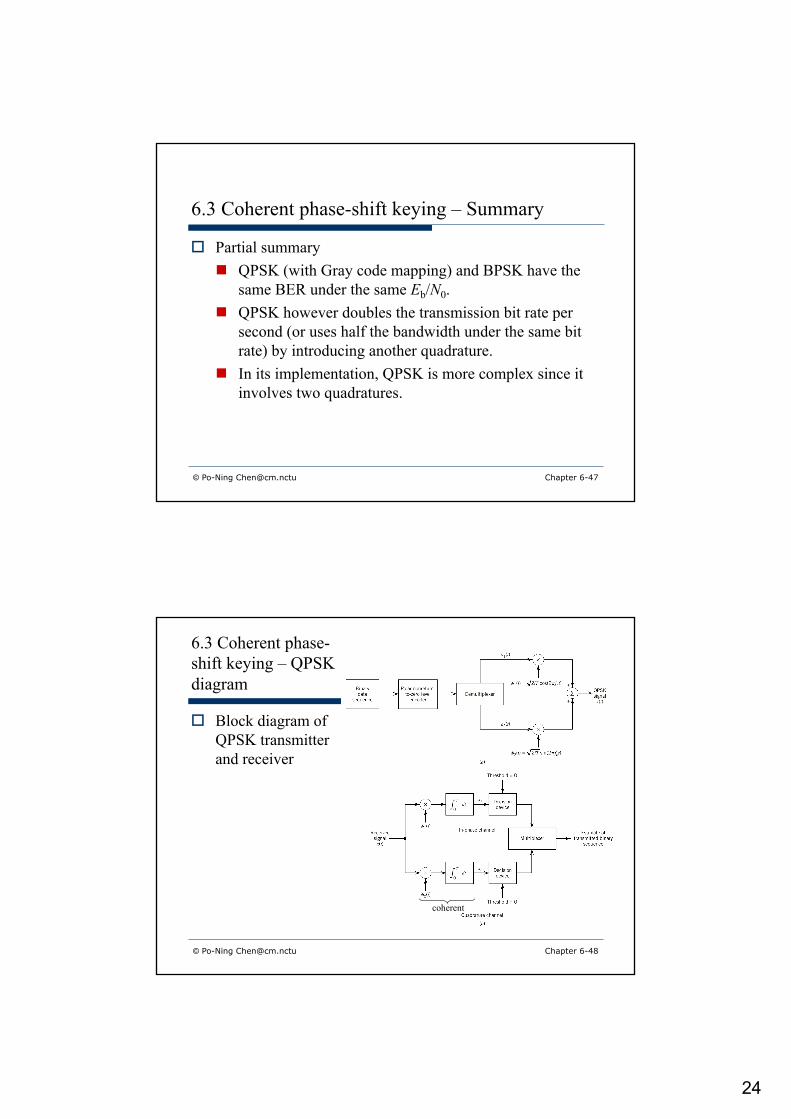
6.3 Coherent phase-shift keying – Summary
o Partial summaryn QPSK (with Gray code mapping) and BPSK have the
same BER under the same Eb/N0.n QPSK however doubles the transmission bit rate per
second (or uses half the bandwidth under the same bit rate) by introducing another quadrature.
n In its implementation, QPSK is more complex since it involves two quadratures.
© Po-Ning [email protected] Chapter 6-48
6.3 Coherent phase-shift keying – QPSK diagram
o Block diagram of QPSK transmitter and receiver
coherent

25
© Po-Ning [email protected] Chapter 6-49
6.3 Coherent phase-shift keying – Sequential baseband signal
o Sequence of complex baseband signalsn No autocorrelation function of one-shot (namely, single)
random variable.n Calculation of autocorrelation function requires a
random process.
© Po-Ning [email protected] Chapter 6-50
6.3 Coherent phase-shift keying – Sequential baseband signal

26
© Po-Ning [email protected] Chapter 6-51
6.3 Coherent phase-shift keying – Autocorrelation function
o Power spectrum of BPSK and QPSK under the same Eb and Tb
0
0.2
0.4
0.6
0.8
1
1.2
1.4
1.6
1.8
2
0 0.5 1 1.5 2
QPSK
BPSK
© Po-Ning [email protected] Chapter 6-52
6.3 Coherent phase-shift keying – Offset QPSK
90+90=180 degreephase shift
90+0=90 degreephase shift
90 degree
90 degree
90 degree
0 degree
o Example 6.1: n QPSK
Single sign change = 90 degree shiftDouble sign change = 180 degree shift

27
6.3 Coherent phase-shift keying – Offset QPSK
90 degreephase shift
90 degreephase shift
90 degreephase shift
o Example 6.1: n Offset QPSK
© Po-Ning [email protected] 6-53
© Po-Ning [email protected] Chapter 6-54
6.3 Coherent phase-shift keying – Offset QPSK
o Offset QPSKn By “offseting” the quadrature component by half a symbol interval
with respect to the in-phase component, Offset QPSK limits the amplitude fluctuation to 90 degree.
n The 90 degree phase transition in OQPSK occurs twice as frequently encountered in QPSK.o Personal comment: One 180 degree phase transition in QPSK
becomes two 90 degree phase transitions in OQPSK. Hence, “twice” is an over-estimate.
n Under AWGN and coherent receiver, the error rate of OQPSK is exactly the same as that of QPSK.

28
© Po-Ning [email protected] Chapter 6-55
o p/4-shifted DQPSK (D=Differential)n The input dibit does not determine the absolute phase,
but the phase change.
6.3 Coherent phase-shift keying – p/4-shifted DQPSK
© Po-Ning [email protected] Chapter 6-56
6.3 Coherent phase-shift keying – p/4-shifted DQPSK
o p/4-shifted DQPSKn The phase transition is restricted to either 45 or 135
degree. o No 0 degree phase transition occurs now!
n Noncoherent receiver is feasible.

29
© Po-Ning [email protected] Chapter 6-57
6.3 Coherent phase-shift keying – Detection of p/4-shifted DQPSK
o Noncoherent receivern Differential detector
© Po-Ning [email protected] Chapter 6-58
6.3 Coherent phase-shift keying – M-ary PSK
E is the transmitted energy per M-ary PSK symbol, andT is the symbol duration.
o Vector space analysis of M-ary PSK
o M-ary PSK

30
© Po-Ning [email protected] Chapter 6-59
6.3 Coherent phase-shift keying – M-ary PSK
o Example – 8PSK (Octaphase-shift keying)
© Po-Ning [email protected] Chapter 6-60
6.3 Coherent phase-shift keying – Union bound of M-ary PSK error

31
© Po-Ning [email protected] Chapter 6-61
6.3 Coherent phase-shift keying – Union bound of M-ary PSK error
o If the signal constellation is symmetric in the sense that
then
© Po-Ning [email protected] Chapter 6-62
6.3 Coherent phase-shift keying – Union bound of M-ary PSK error
o Example – 8PSK
32
© Po-Ning [email protected] Chapter 6-63
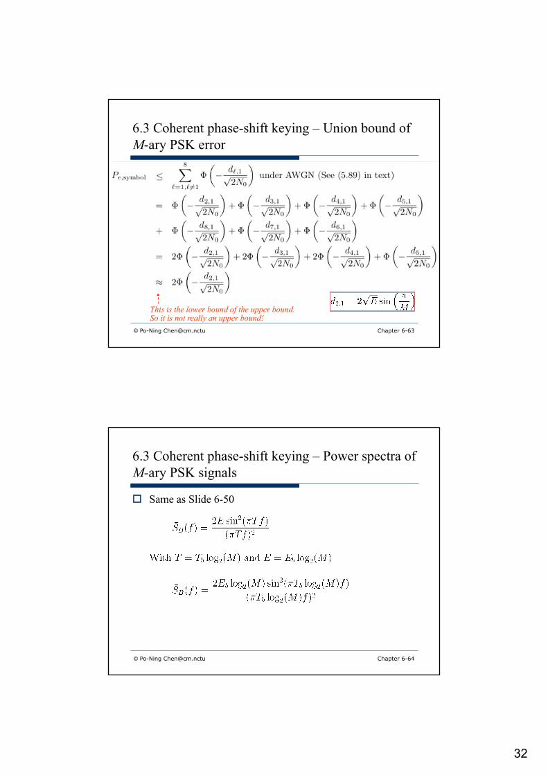
6.3 Coherent phase-shift keying – Union bound of M-ary PSK error
This is the lower bound of the upper bound.So it is not really an upper bound!
© Po-Ning [email protected] Chapter 6-64
6.3 Coherent phase-shift keying – Power spectra of M-ary PSK signals
o Same as Slide 6-50

33
© Po-Ning [email protected] Chapter 6-65
6.3 Coherent phase-shift keying – Power spectra of M-ary PSK signals
© Po-Ning [email protected] Chapter 6-66
6.3 Coherent phase-shift keying – Bandwidth efficiency
o Bandwidth efficiency of M-ary PSK signalsn Null-to-null bandwidth
n Bandwidth efficiency
34
Chapter 6-67
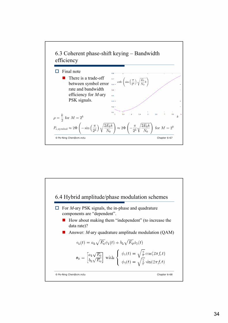
6.3 Coherent phase-shift keying – Bandwidth efficiency
o Final noten There is a trade-off
between symbol error rate and bandwidth efficiency for M-aryPSK signals.
© Po-Ning [email protected]
© Po-Ning [email protected] Chapter 6-68
6.4 Hybrid amplitude/phase modulation schemes
o For M-ary PSK signals, the in-phase and quadrature components are “dependent”.n How about making them “independent” (to increase the
data rate)?n Answer: M-ary quadrature amplitude modulation (QAM)

35
© Po-Ning [email protected] Chapter 6-69
6.4 Hybrid amplitude/phase modulation schemes
o Square constellation
n Gray-encoded quadbitso Gray-encode the first two
bits by quadrants (PSK)o Gray-encode the
remaining two bits within quadrants (ASK)
PSK
© Po-Ning [email protected] Chapter 6-70
6.4 Hybrid amplitude/phase modulation schemes
o Symbol error rate of square QAM
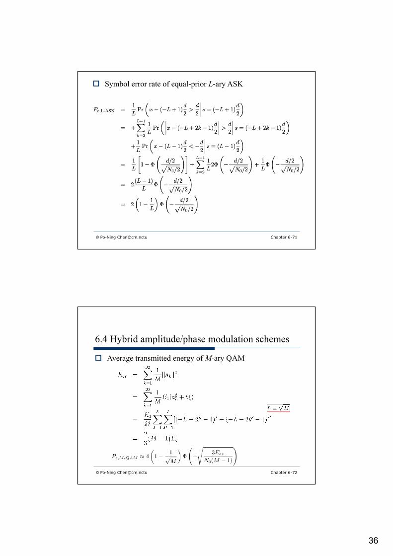
o Symbol error rate of equal-prior L-ary ASK
36
o Symbol error rate of equal-prior L-ary ASK
© Po-Ning [email protected] Chapter 6-71
© Po-Ning [email protected] Chapter 6-72
6.4 Hybrid amplitude/phase modulation schemes
o Average transmitted energy of M-ary QAM

37
© Po-Ning [email protected] Chapter 6-73
6.4 Hybrid amplitude/phase modulation schemes
o Square constellation QAMn M is usually even power of
two. n For example, M = 22, 24, 26,
28, … (in such case L = 2, 22, 23, 24, …)
o Question: How about M = 23, 25, 27, …n Answer: Cross
constellation QAM
© Po-Ning [email protected] Chapter 6-74
6.4 Hybrid amplitude/phase modulation schemes
o Symbol error rate of cross-constellation QAM
38
© Po-Ning [email protected] Chapter 6-75
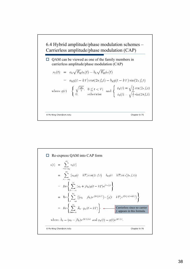
6.4 Hybrid amplitude/phase modulation schemes –Carrierless amplitude/phase modulation (CAP)
o QAM can be viewed as one of the family members in carrierless amplitude/phase modulation (CAP)
o Re-express QAM into CAP form
© Po-Ning [email protected] Chapter 6-76
Carrierless since no carrier fc appears in this formula.

39
© Po-Ning [email protected] Chapter 6-77
6.4 Hybrid amplitude/phase modulation schemes –Carrierless amplitude/phase modulation (CAP)
o Properties of the passband in-phase and quadrature pulses in CAP
n Property 1:
© Po-Ning [email protected] Chapter 6-78
6.4 Hybrid amplitude/phase modulation schemes –Carrierless amplitude/phase modulation (CAP)

40
© Po-Ning [email protected] Chapter 1-79
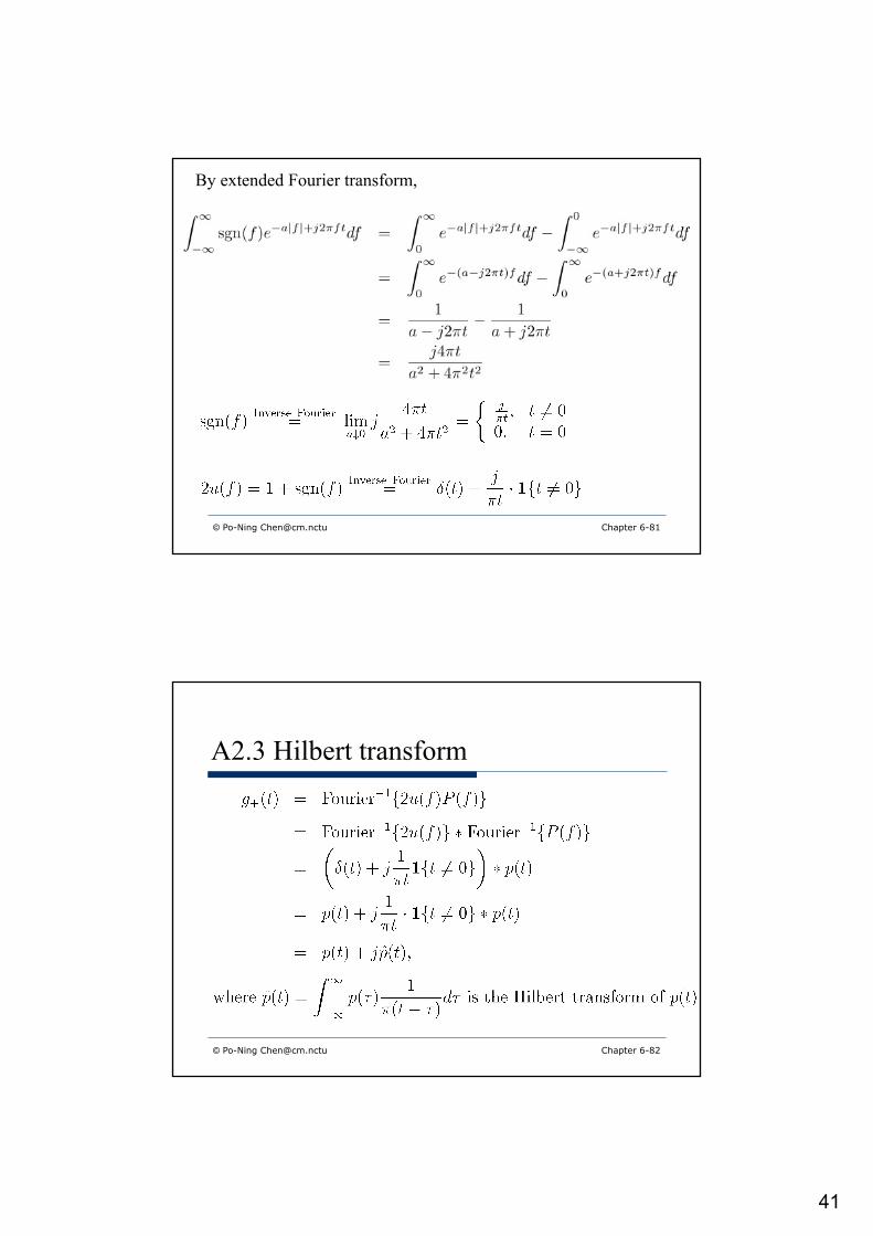
A2.3 Hilbert transform
o Let P(f) be the spectrum of a real function p(t).n By convention, denote by u(f) the unit step function,
i.e.,
o Put g+(t) to be the function corresponding to 2u(f)P(f).
Multiply by 2 to unchange the area.
Chapter 6-79
© Po-Ning [email protected] Chapter 1-80
A2.3 Hilbert transform
o How to obtain g+(t)?o Answer: Hilbert Transformer.
Proof: Observe that
Then by the next slide, we learn that
Chapter 6-80
41
© Po-Ning [email protected] Chapter 1-81
By extended Fourier transform,
Chapter 6-81
© Po-Ning [email protected] Chapter 1-82
A2.3 Hilbert transform
Chapter 6-82

42
© Po-Ning [email protected] Chapter 1-83
A2.3 Hilbert transform
ptt 1) =(h
Chapter 6-83
© Po-Ning [email protected] Chapter 1-84
6.4 Hybrid amplitude/phase modulation schemes –Carrierless amplitude/phase modulation (CAP)
Chapter 6-84

43
© Po-Ning [email protected] Chapter 1-85
A2.3 Hilbert transformn Hence, Hilbert
transform is basically a 90 degree phase shifter.
Chapter 6-85
© Po-Ning [email protected] Chapter 1-86
A2.3 Hilbert transform
ptt 1) =(h
ptt 1) =(h Ä
1-Chapter 6-86

44
© Po-Ning [email protected] Chapter 1-87
A2.3 Hilbert Transform
o An important property of Hilbert transform is that:
(Examples of Hilbert transform pairs can be found in Table A6.4.)
Chapter 6-87
© Po-Ning [email protected] Chapter 1-88Chapter 6-88

45
© Po-Ning [email protected] Chapter 6-89
6.4 Hybrid amplitude/phase modulation schemes –Carrierless amplitude/phase modulation (CAP)
o Properties of the passband in-phase and quadrature pulses in CAPn Property 2:
n Property 3:
o This is similar to use another pulse shaping function as g(t)*l(t).
o One is thus free to choose the pulse shaping function (to, e.g., improve the bandwidth efficiency) without affecting the orthogonality of two quadratures.
o Example 6.4: Bandwidth-efficient spectral shapingn a = 0.2
© Po-Ning [email protected] 6-90
46
© Po-Ning [email protected] Chapter 6-91
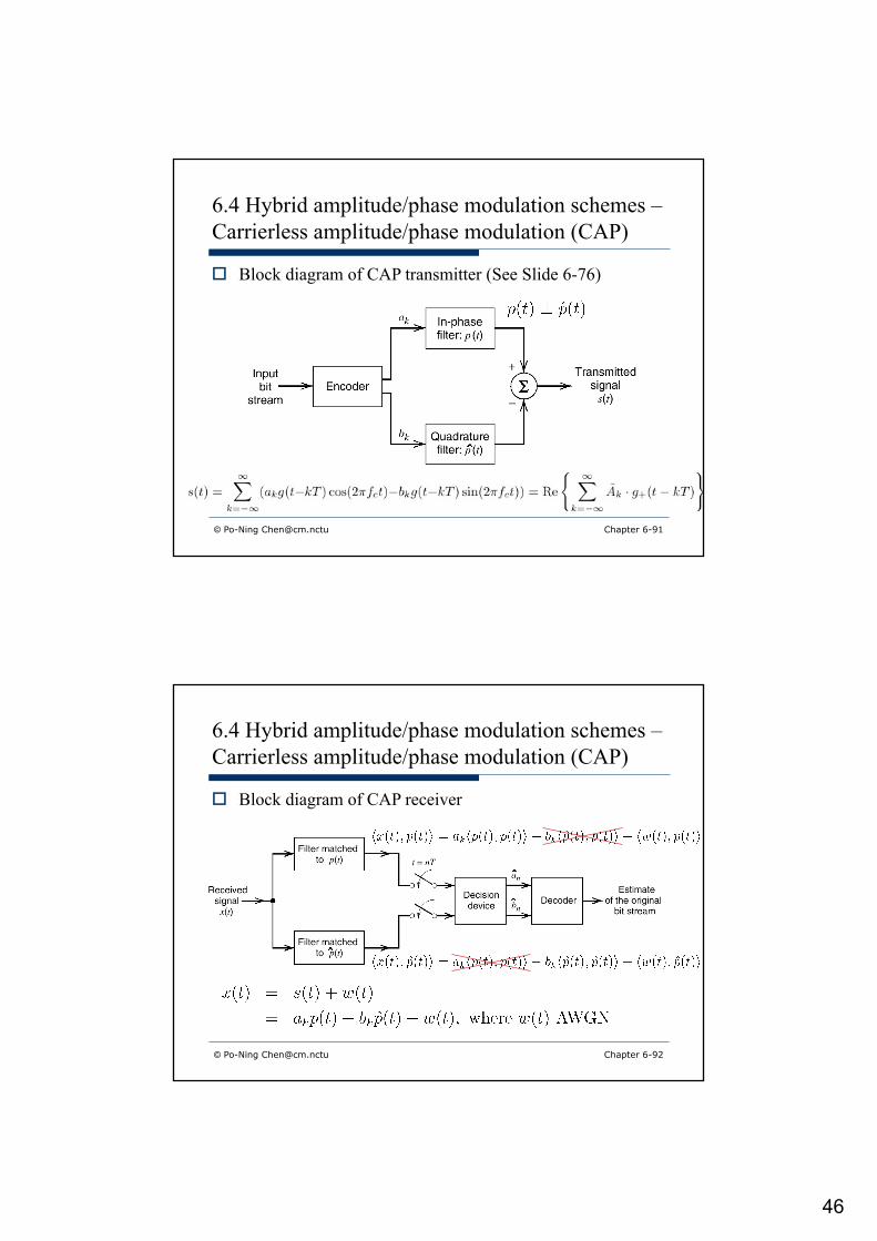
6.4 Hybrid amplitude/phase modulation schemes –Carrierless amplitude/phase modulation (CAP)
o Block diagram of CAP transmitter (See Slide 6-76)
© Po-Ning [email protected] Chapter 6-92
6.4 Hybrid amplitude/phase modulation schemes –Carrierless amplitude/phase modulation (CAP)
o Block diagram of CAP receiver

47
© Po-Ning [email protected] Chapter 6-93
6.4 Hybrid amplitude/phase modulation schemes –Carrierless amplitude/phase modulation (CAP)
o How about channels with intersymbol interferences, in addition to AWGN?
Lineartime-variant
filter h(t)
Channel w(t)
s(t) x(t)+
o Recall in Section 4.9: Optimum linear receiver.
n Design of receiver c(t) as an MMSE equalizer
© Po-Ning [email protected] Chapter 6-94
Recall the below terms:1. Zero-forcing equalizer2. Nyquist criterion/ISI3. Noise enhancement4. MMSE equalizer

48
© Po-Ning [email protected] Chapter 6-95
6.4 Hybrid amplitude/phase modulation schemes –Carrierless amplitude/phase modulation (CAP)
o This leads to Fig. 6.23 in text.
o Can we implement the above structure in “digital” form?
© Po-Ning [email protected] Chapter 6-96
6.4 Hybrid amplitude/phase modulation schemes –Carrierless amplitude/phase modulation (CAP)
Combine into one FIR filter
May be adaptive when required

49
© Po-Ning [email protected] Chapter 6-97
6.4 Hybrid amplitude/phase modulation schemes –Carrierless amplitude/phase modulation (CAP)
o Applications of CAPn Passband transmission of digital data over twisted-pair
wiring of lengths less than 100m.n Data rates may range from 51 upto 155 Mbps with
bandwidth being strictly limited to 30 MHz.
© Po-Ning [email protected] Chapter 6-98
6.5 Coherent frequency-shift keying
o (M-ary) ASK, (M-ary) PSK and (M-ary) FSK are three major categories of digital modulations, in which QAM can be viewed/analyzed similarly to (M-ary) PSK.
o In this section, the last one, i.e., (M-ary) FSK, will be introduced and discussed.

50
© Po-Ning [email protected] Chapter 6-99
6.5 Coherent frequency-shift keying
Eb is the transmitted energy per bit, andTb is the bit duration.
o Vector space analysis of binary FSK
o Binary FSK
© Po-Ning [email protected] Chapter 6-100
With this multiple-(1/Tb) restriction, it becomes “continuous-phase” in every inter-bit transition. Such kind of forced “continuous-phase” signals, known as Sunde’s FSK, surely belongs to the general continuous-phase FSK (CPFSK) family.
E. D. Sunde, "Ideal binary pulse transmission by AM and FM," Bell Labs Technical Journal, 38, pp. 1357-1426, November 1959.


![Stepped-impedance lowpass filters with spurious passband ... 2004.pdf · formulas [7]), and by using a commercial transmission line calculator (Agilent LineCalc) the geometry of](https://static.fdocuments.us/doc/165x107/5e04fb70efb0494d2a43ee50/stepped-impedance-lowpass-ilters-with-spurious-passband-2004pdf-formulas.jpg)
