Chapter 6 Engineering Approach - openjicareport.jica.go.jp
144
Data Collection Survey on Thankot Area Road Improvement in Nepal Final Report 6-1 Chapter 6 Engineering Approach 6.1 Geological and Hydrological Investigations 6.1.1 Geological Investigation The result of geological investigation conducted on the optimum route, the Alternative-C is briefly discussed in this section. (1) Geological Reconnaissance Survey Surface geological reconnaissance survey was conducted along the earthen section (approach road L=approx.2.225km) of the proposed road using a 1:25,000 scale topography map. The result of the survey is shown in the geological plan and profile Figure 6-1 1) Approach Road The geology along the approach road consists of lacustrine soil and debris sediment which covers the lacustrine soil layer. Furthermore, soft clay layer is found distributed along the river bed. ・ Lacustrine soil has been reported to be up to 125m or more in the vicinity of the study area. This layer is assumed to consist of alternate layers of gravel, clay layer and organic clay layer including a portion of soft soil, where high embankment may encounter potential land subsidence. In addition, discharge of groundwater has also been confirmed from existing boreholes. ・ The debris flow is mainly carried down from the Chandragiri Mountain on the east side and the debris flow consists of gravel containing withered or unconsolidated rock mass. The thickness of the layer is assumed to be 10-30m and the material is suitable to be used as fill material. ・ The river bed sediment is formed from unconsolidated clay and the layer thickness is assumed to be within several meters. 2) Bridge site There are three locations where bridges are proposed. Out of the three, the geology of the first two locations near to the divergence point from existing road at Kisipindi, about 4.8km from Kalanki, consists of consolidated sandy soil and the bearing layer at these locations are considered to be relatively shallow. The other bridge located on the bottom of the basin, has its surface composed of bed sediment containing clay or gravel. The geology deep below the surface is unknown and drilling is unavoidable to confirm the bearing layer.
Transcript of Chapter 6 Engineering Approach - openjicareport.jica.go.jp

Data Collection Survey on Thankot Area Road Improvement in Nepal Final Report
6-1
Chapter 6 Engineering Approach
6.1 Geological and Hydrological Investigations
6.1.1 Geological Investigation The result of geological investigation conducted on the optimum route, the Alternative-C is briefly discussed in this section.
(1) Geological Reconnaissance Survey Surface geological reconnaissance survey was conducted along the earthen section (approach road L=approx.2.225km) of the proposed road using a 1:25,000 scale topography map. The result of the survey is shown in the geological plan and profile Figure 6-1
1) Approach Road The geology along the approach road consists of lacustrine soil and debris sediment which covers the lacustrine soil layer. Furthermore, soft clay layer is found distributed along the river bed.
・ Lacustrine soil has been reported to be up to 125m or more in the vicinity of the study area. This layer is assumed to consist of alternate layers of gravel, clay layer and organic clay layer including a portion of soft soil, where high embankment may encounter potential land subsidence. In addition, discharge of groundwater has also been confirmed from existing boreholes.
・ The debris flow is mainly carried down from the Chandragiri Mountain on the east side and the debris flow consists of gravel containing withered or unconsolidated rock mass. The thickness of the layer is assumed to be 10-30m and the material is suitable to be used as fill material.
・ The river bed sediment is formed from unconsolidated clay and the layer thickness is assumed to be within several meters.
2) Bridge site There are three locations where bridges are proposed. Out of the three, the geology of the first two locations near to the divergence point from existing road at Kisipindi, about 4.8km from Kalanki, consists of consolidated sandy soil and the bearing layer at these locations are considered to be relatively shallow. The other bridge located on the bottom of the basin, has its surface composed of bed sediment containing clay or gravel. The geology deep below the surface is unknown and drilling is unavoidable to confirm the bearing layer.

Data C
ollection Survey on Thankot Area Road Improvem
ent in Nepal
Final Report
6-2
TE-1
TC-1
TD-1
Bed Rock Lacustrine soil
Debri
River deposit
Debri
Bed Rock River deposit
Lacustrine soil
Lacustrine soil
Source: JICA Study Team
Figure 6-1 Geological Plan and Geological Profile along C route

Data Collection Survey on Thankot Area Road Improvement in Nepal Final Report
6-3
3) Tunnel Section The geology along the tunnel section is as follows;
・ The earth at the east side tunnel portal is made of colluvial soil from the surrounding mountain.
・ Large portion of the section including the west side tunnel portal consists of interbedded sandstone/phyllite. The inclination of the strata is in the same direction of the tunnel, which is about 50-70 degrees sloped to the south.
・ The thickness of sandstone is about 5-30cm, and interbedded phyllite is 1-10cm.
4) Fracture Zone and Faults According to the previous geological survey, Existence of an active fault (Kathmandu South Fault) in the southeast direction has been reported in previous geological survey report (Gekkan Chikyu No. 31,200). Similarly, linear pattern of fault through Dahachowk and BadBhanjyang has also been reported (Engineering and Environment Geology).
Fractured zone was confirmed at the west ridge of east side (Kathmandu side) tunnel portal during the field survey. However the direction and length of the fault is unknown at present and further needs a detailed geological survey.
5) Groundwater There are several settlement areas along the proposed route. The source of water for drinking as well as for other domestic use for these areas is basically a well dug in front of a house. Also, surface runoff is used for irrigation water for paddy fields around the area. Therefore, ground water is a very valuable asset. Tunnel for the proposed route is planned at the north side of the valley (basin). The west side tunnel portal is about 80-100m lower than that of the elevation of this basin. The leakage of groundwater from the tunnel is anticipated to have an impact on the groundwater of the above-mentioned settlement areas and even contribute in decreasing the groundwater level. Therefore, a detailed groundwater survey and management plan will be required in the further studies.
Photo 6-1 Outcrop at Tunnel Exit

Data Collection Survey on Thankot Area Road Improvement in Nepal Final Report
6-4
(2) Drilling and Laboratory Test Drillings were carried out at tunnel portals (east side and west side) on all proposed alternatives to identify and confirm the topographic condition of the area. An additional drilling was conducted on the east side tunnel portal on Alternative-C due to the fact that the core samplings were not properly extracted as the bedrock was highly weathered. As a result, altogether drilling was conducted at 5 locations as depicted in Figure 6-2. The total length of drilling was
120m. By TC-1, permeability test was conducted three times. k = 2.26E-6 ~ 1.69E-7 m/sec is obtained that the permeability of the ground normal.
Log tables in Figure 6-3 show the results of drilling. The details are attached in the appendix. Laboratory soil tests were also conducted on the core samples collected. The results of the tests are summarized in Table 6-1. Both the unit weight and water content showed an average value. However, the unconfined compressive strength one of the indicators for performance of tunnel excavation showed a maximum value of 135kg/cm3. Incapability to extract rock samples properly or development of the bedding plane in 20-30 degrees with respect to vertical direction is possible reasons. In normal condition, the value is expected to be larger.
Table 6-1 Laboratory Test Results
Source: JICA Study Team
Figure 6-2 Drilling Locations Source: JICA Study Team

Data Collection Survey on Thankot Area Road Improvement in Nepal Final Report
6-5
Colluivial Soil
Colluivial Soil
Clay Gravel Clay
Sand stone and Phyllite
Sand stone and Phyllite
Sand stone and Phyllite
Sand stone and Phyllite
Gravel ClayGravel
Figu
re 6
-3
Sim
ple
Bor
ing
Log
s
Sour
ce: J
ICA
Stu
dy T
eam

Data Collection Survey on Thankot Area Road Improvement in Nepal Final Report
6-6
(3) Further Necessary Investigations From the result of drilling at the east side tunnel portal, distribution of hard rock was not confirmed. Therefore, the distribution is judged to be heavily weathered and softened bedrock. Even though the consideration was taken to shift the alignment towards the north so that the tunnel section will pass through bed rock foundation, the geological distribution of the basin at the west of the portal is unknown. Therefore, the Study Team recommends reviewing the alignment after confirming the location of the bed rock foundation by conducting more detailed (highly accurate) drilling together with reference to the results of the electrical resistivity tomography test performed by DOR during its Feasibility Study in 2013. A set of tests such as seismic refraction tomography, electrical resistivity, advanced drilling also are considered to be inevitable.
Furthermore, a detailed hydrological investigation is also deemed necessary to avoid the potential impact on the groundwater of the surrounding areas during excavation of the tunnel. This will include continuous observation of groundwater level in wells and the overflow of the discharges of the rivers into the surrounding areas.
Data Collection Survey on Thankot Area Road Improvement in Nepal Final Report
6-7
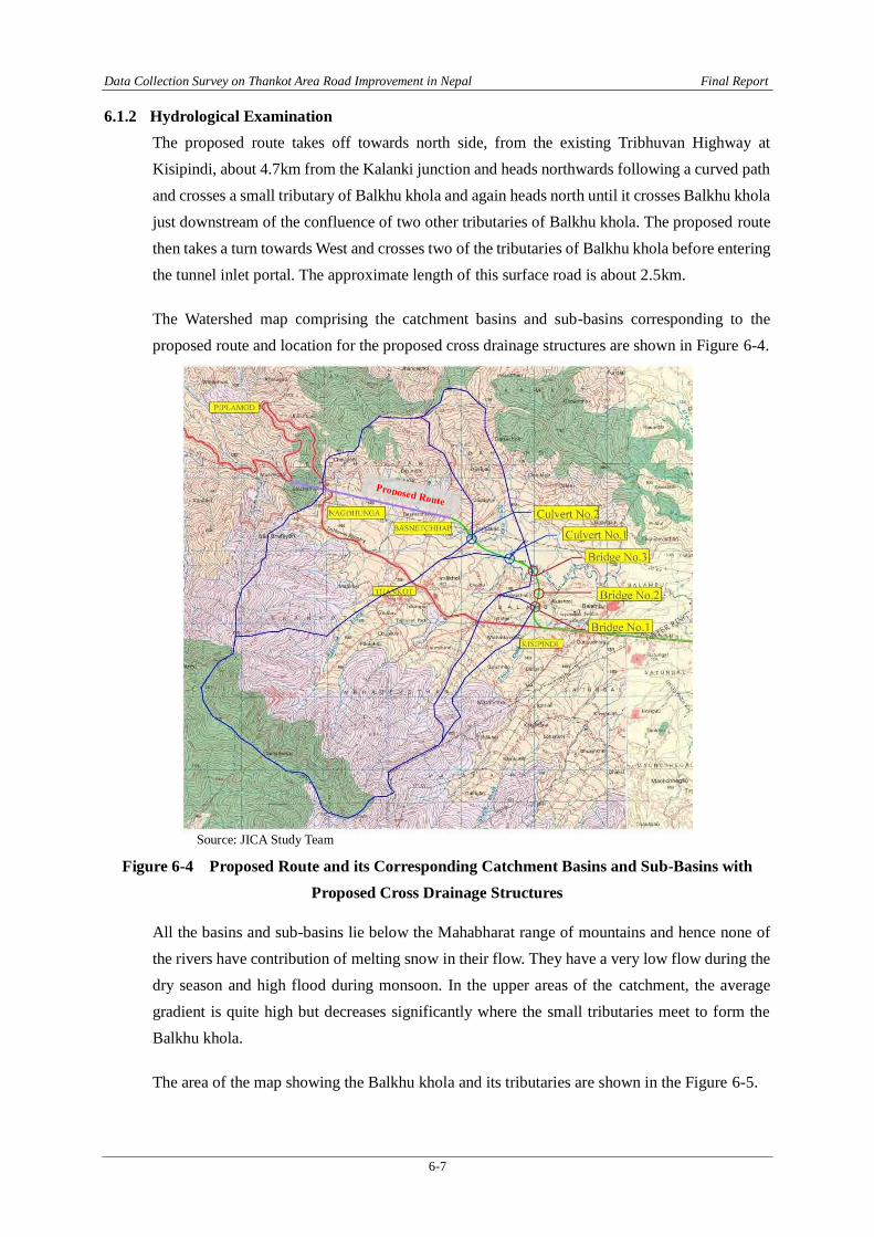
6.1.2 Hydrological Examination The proposed route takes off towards north side, from the existing Tribhuvan Highway at Kisipindi, about 4.7km from the Kalanki junction and heads northwards following a curved path and crosses a small tributary of Balkhu khola and again heads north until it crosses Balkhu khola just downstream of the confluence of two other tributaries of Balkhu khola. The proposed route then takes a turn towards West and crosses two of the tributaries of Balkhu khola before entering the tunnel inlet portal. The approximate length of this surface road is about 2.5km.
The Watershed map comprising the catchment basins and sub-basins corresponding to the proposed route and location for the proposed cross drainage structures are shown in Figure 6-4.
Source: JICA Study Team
Figure 6-4 Proposed Route and its Corresponding Catchment Basins and Sub-Basins with Proposed Cross Drainage Structures
All the basins and sub-basins lie below the Mahabharat range of mountains and hence none of the rivers have contribution of melting snow in their flow. They have a very low flow during the dry season and high flood during monsoon. In the upper areas of the catchment, the average gradient is quite high but decreases significantly where the small tributaries meet to form the Balkhu khola.
The area of the map showing the Balkhu khola and its tributaries are shown in the Figure 6-5.

Data Collection Survey on Thankot Area Road Improvement in Nepal Final Report
6-8
Source: JICA Study Team
Figure 6-5 Topographic Map showing Balkhu khola and its Tributaries near the Proposed Route
At one of the tributary of Balkhu khola that the route crosses, a deep gorge of about 15m exists and a bridge has been proposed (Bridge No.1). Likewise, another bridge is proposed at a land depression area of about 10m and is approximately 25m wide (Bridge No.2).
In the present sites, the road geometric requirement has become the dominant parameter in deciding the sizes of the cross drainage structure, both in span and height rather than that hydrological requirements. Thus, because of the road gradient requirements, the height of bridges/culverts has becomes more deciding than that is required from hydrological consideration.
(1) Study of Major Crossings within the Proposed Route
1) Proposed Bridge Site for Bridge No.1 The proposed bridge site for Bridge No.1 is over a small tributary of Balkhu Khola. The stream is in a deep gorge of about 15m. At this site, in the dry season, the waterway of the stream is narrow, about 7m only and the depth of water is shallow. By contrast, the width of the stream at the formation level of the proposed road is about 40m. Hence, the length of bridge has been estimated as 20m at this site.
Source: JICA Study Team Photo 6-2 Proposed Bridge Site for Bridge No.1
Proposed Route
Towards Tunnel
Flow Direction
Towards Tribhuvan Highway

Data Collection Survey on Thankot Area Road Improvement in Nepal Final Report
6-9
Moreover, a lot of vegetation covers the drainage line of the stream and also on the adjacent terraces many trees are present as seen in Photo 6-2. Land, on the right bank of the stream, has been used for mushroom farming and on the left bank there is a stone paved road. As per the local residents of the area, during monsoon season the water level in the stream rises to about 2m from the stream bed level. Therefore, the proposed deck level of the bridge is at a very safe height. Also, in this case, the geometrical requirement of the road design has acted as a dominant factor in setting the profile of the road.
2) Proposed Bridge Site for Bridge No.2 The proposed bridge site for Bridge No.2 is not a stream, it is a valley. However, very small surface discharge is observed during monsoon as a result of water draining from the surrounding. The depression is about 10m deep and 30m wide. This patch of land is usually used for grazing purpose by the locals. Also, at certain intervals in the depression, projection of manhole covers could be seen which confirms the existence of underground drainage system, which ultimately drains into the Balkhu Khola.
A dry bridge of about 10m has been proposed at this site. Since it is a dry bridge, the HFL determination is not needed. The upstream section of the bridge site is shown in Photos 6-3.
(a) Proposed Bridge Site (b) Up Stream View
Source: JICA Study Team
Photos 6-3 Proposed Bridge Site for Bridge No.2
3) Proposed Bridge Site for Bridge No.3 The proposed bridge site for Bridge No.3 is over the main Balkhu Khola. The proposed bridge axis lies in the meander of the stream. The river is shallow during the dry period with very little flow but at the time of flood, the river spreads laterally and linear waterway reaches almost 50m, inundating the nearby flood plain, which in dry season is used for cultivation. The lateral spread of the flood is more prominent on the right bank than on the left as the elevation of right bank is lower than that of the left bank.
In addition, river bank cutting is also prevalent in this river near the bridge site. The bridge axis, being in the meander of the river, needs special protection as the concave banks are prone to erosion. Bridge of about 50m has been proposed at this site and associated river
Towards Tunnel
Towards Highway

Data Collection Survey on Thankot Area Road Improvement in Nepal Final Report
6-10
training works are also needed for the safe passage of flood. According to the local people the rise in water level is about 2.5m from the bed level, during flood. Hence the proposed deck level should be well above this elevation including adequate room for freeboard.
(a) Proposed Bridge Site (b) Bird’s Eye View Source: JICA Study Team
Photos 6-4 Proposed Bridge Site for Bridge No.3
4) Culvert No.1 The stream is one of the tributaries of Balkhu Khola draining from the north of the watershed of Balkhu Khola. A little upstream of the proposed culvert site, there exists a slab culvert of about 5m length and having an opening of approximately 2m depth. Just upstream of the bridge site the stream takes a sharp curved path and also the stream has been heavily channelized to approximately 50-60m upstream.
At this section of the stream, the flood has not exceeded the banks, according to the local residents. However, the increasing trend of channelizing the stream into a narrower width and encroachment of the nearby lands fuelled with increased surface flow due to rapid urbanization could significantly raise the water levels in the stream during flood time. Therefore the design level should be adequately high such that passage of flood is safe. Consequently, high flood level, at least 1.5m higher from the current stream bed level is suggested for this stream. Also, standard freeboard height should be provided for the culvert.
(a) Proposed Culvert Site (b) Upstream Channelized Section Source: JICA Study Team
Photos 6-5 Proposed Culvert Site No.1
Towards Tunnel
Towards Highway
Towards Tunnel
Towards Highway
Balkhu Khola Flow
Towards Tunnel
Towards Highway

Data Collection Survey on Thankot Area Road Improvement in Nepal Final Report
6-11
5) Culvert No.2 This stream is also one of the tributaries of Balkhu Khola. The proposed section is about 5m wide and the stream has a low flow during dry season. The stream is extremely polluted with stagnant heaps of garbage in the waterway. Either banks are used for cultivation. It is suggested to keep the HFL at least 1.5m above the current bed level at the proposed site.
(2) Discharge Estimation For the present phase of the study, discharge in the streams where cross drainage structures are required, has been calculated using two methods, namely, WECS/DHM method and Rational Method. The former is a local empirical formula widely used in Nepal. Brief description of each method is given below.
1) Water and Energy Commission Secretariat (WECS/DHM) Method The WECS/DHM method, based on flood frequency analysis, is recommended for the context of Nepal after performing few case studies. In this method, the most significant independent variable is the area of the basin below 3000m elevation. This area represents the portion of the basin that is influenced by monsoon precipitation. The results of this method are not applicable to basins located entirely above 3000m elevation. Also, even if the proportion of a basin lying below 3000m is very small, the results of this method will not be particularly reliable.
As per the recommendation of the Water and Energy Commission Secretariat / Department of Hydrology and Meteorology (WECS/DHM) of Nepal, the flood flows of any river of catchment area A (km²) lying below 3000m elevation are given by:
Instantaneous Peak flood for a return period of 2 years, Q2 = 1.8767 (A + 1)0.8783 Instantaneous Peak flood for a return period of 100 years, Q100 = 14.63 (A + 1)0.7342 The flood flow for any other return period, T years, can be found as:
QT = exp (ln Q2 + sσ) Where,
A = area below 3000m elevation σ = standard deviation of natural logarithms of annual floods = ln (Q100 / Q2) / 2.326 s = Standardised normal variate from a particular return period
= 0, 0.842, 1.282, 1.645, 2.054, 2.326, and 2.576 for T = 2, 5, 10, 20, 50, 100, and 200 years, respectively.
Photo 6-6 Proposed Culvert Site No.2 Source: JICA Study Team
Towards Tunnel
Towards Highway

Data Collection Survey on Thankot Area Road Improvement in Nepal Final Report
6-12
2) Rational Method The design intensity of rainfall corresponding to the time of concentration is determined from IDF curve. The time of concentration is determined using Kirpich equation. Most of the catchment area lies in hilly terrain and covered by vegetation. So the average coefficient of runoff is taken as 0.4 for the application of Rational method.
𝐐𝐭 =𝐂 ∗ 𝐈𝐂𝐭 ∗ 𝐀
𝟑. 𝟔
Where, Qt= discharge at return period t years in m3/s C = Average Runoff coefficient Ict= Intensity of rainfall corresponds to t years return period in mm/hr A = Catchment area in sq. Km
3) Results of the Estimated Discharge In Nepal, for the design of major bridge, 100 year return period flood value is taken as the design discharge and for the culverts 50 year return period flood is taken as the design discharge. Therefore, for all the basins, 50 year and 100 year return period flood has been computed and presented in the following table.
Table 6-2 Results of Estimated Discharge for Each Basin
Hydrologic element
Basin area (km2)
100 years return period flood (m3/s)
50 years return period flood (m3/s)
Recommended Design Discharge (m3/s)
WECS method Rational WECS
method Rational
Bridge 1 0.72 21.81 10.52 17.31 9.39 10.52
Bridge 3 15.03 112.24 146.88 92.50 131.08 146.88
Culvert 1 7.2 68.61 84.19 55.91 75.14 75.14
Culvert 2 5.65 58.83 71.08 47.77 63.44 63.44 Note: Site for Bridge No.2 is not a stream Source: JICA Study Team
The discharge calculated using Rational Formula has been recommended because; this method takes into account the rainfall data in the vicinity/or of the watershed. Also it considers the runoff coefficient accounting for all differences between the rainfall intensity and the flood peak which gives a more reliable result.
(3) High Flood Level Estimation For the present phase of the study, High Flood Level (HFL) was estimated by inquiring the knowledgeable local people at the site. In Bridge No. 1 and Bridge No. 3, where there is water flow, the proposed road alignment profile significantly exceeds the assumed HFL. Also, in case of the Culvert Nos. 1 and 2, the proposed profile is in embankment, rising approximately 10m

Data Collection Survey on Thankot Area Road Improvement in Nepal Final Report
6-13
from the current ground level, which further reassures that the alignment is at a safe height, markedly exceeding the hydrological requirement.
However, for the proposed Bridge No. 2, there is no water flow and is only a dry bridge, thus HFL consideration is not relevant.
Schematic cross sections of the bridge sites are shown below.
(A) Schematic Cross-Section at Bridge Site No.1
(B) Schematic Cross-Section at Bridge Site No.2
(C) Schematic Cross-Section at Bridge Site No.3 Source: JICA Study Team
Figure 6-6 Schematic Cross-Section at Bridges

Data Collection Survey on Thankot Area Road Improvement in Nepal Final Report
6-14
(4) Limitations and Future Recommendation The main objective of the above hydrological study was to verify the different locations of major river crossings along the proposed route. The hydrological study is concentrated in estimating the approximate High Flood Levels (HFL) at the stream crossings for the judgment of bridge deck levels. However, there are no gauging stations in any of the streams within the Project Area. In the absence of flood data of the rivers the flood determination has been estimated by empirical methods and Rational Method only. For the present phase of the study, HFL was also verified by inquiring the knowledgeable local people at the site. However, in the higher stages of the study, different methods of rainfall-runoff analysis is recommended to be carried out to determine flood of various frequencies and based on the actual cross-sectional surveys of the waterway corridor.
(5) Ground-WaterInfiltration into the Tunnel The proposed route of the Thankot tunnel is seen passing through highly weathered metasandstone and partly through soft ground of valley fills material or colluvium materials. There are total five number of drill holes (TA-1, TB-2, TC-1, TE-1 and TD-1) has been drilled along the alignment or nearby proposed tunnel route.
The ground water table measured during the drilling in the drill holes is observed at the surface in drill hole TA-1, TB-2, TC-1 and at 2.20m in TE-2, similarly there was no ground water table encountered in the drill hole TD-1 (Outlet portal side). Pizometric Level reading on the Standing Pipes and the results of the falling head permeability test is shown in the Table below.
Table 6-3 Ground Water Table , Permeability and Pizometric Level Readings of Boreholes Borehole No. Borehole Depth Ground Water Table Pizometric Level Average Permeability
TA – 1 0.00m NP NP
TB – 1 0.00m NP NP TD – 1 Dry NP NP
TE – 1 2.20m NP NP
TC –1
0.00m 11.1m +0.4m 1.69 x 10⁻⁷ m/sec 18.0m +1.92m 8.2 x 10⁻⁷ m/sec 30m +3.00m 2.26 x 10⁻⁶ m/sec
NP: Not Performed Source: JICA Study Team
The information of ground water condition obtained during the drilling is clearly indicating that the beginning section (from Kathmandu Valley side) of tunnel route is passing through below the ground water table. The topography of the alignment is along the toe of the mountain which is the groundwater recharge line of the valley therefore the ground water inflow inside tunnel can be assumed relatively high. Hence the vertical grade of the tunnel alignment is downwards (-3.5%) from valley side (Inlet) to the outlet (other side of the valley). In this condition the possibility of ground water drainage towards outside the valley is very high.

Data Collection Survey on Thankot Area Road Improvement in Nepal Final Report
6-15
It is generally very difficult to predict the location and quantity of the potential water leakage in a planned underground excavation. Permeability testing may give certain indication. A technique is developed by Tokheim and Janbu (1984) for the leakage analysis along the tunnel alignment is called Tokheim and Janbu (1984) method. The method is based on the flow theory and consists of input parameters; i.e., rock mass permeability, geometric factor, hydraulic water head, etc. (equation 1).
It is interesting to note that the estimation of hydraulic conductivity is crucial in this method since the hydraulic conductivity values are mostly estimated in power of 10(-x). An increase in power value by one the leakage will increase by almost 10 times. Therefore, leakage analysis is very sensitive with the use of this method. Still, this approach of leakage estimate is used so that it is possible to see the sensitivity of the method.
Qw = 2π x K x L x p / μw x G (equation 1)
Where Qw = inflow rate (m3/s) K = Specific Permeability (m2) L = Length of tunnel (m) P = potential (active head (Pa)
μw = dynamic viscosity of water (KG/m) = density x cinematic viscosity G = Geometry factor
The Geometry factor (G) describes the flow pattern relatively to the geometry of the tunnel or cavern, and is given
G = ln (2D – r)(L + 2r) / r (L + 2 (2D - r)) (equation 2)
Where D = distance between the center line of the excavation and the ground water table r = “equivalent radius” of idealized geometry, i.e., the radius of a cylinder with a surface area equal to the that of actual excavation
As indicated by the inflow equation, information about permeability is needed for Tokheim and Janbu’s method to be applied. Hence, to be obtained reliable input, permeability testing in boreholes has to be carried out.
The main uncertainty when applying this method is generally represented by the geometry factor (G). The question presented by Tokheim and Janbu were designed originally for a three dimensional flow pattern. In rock mass however, one single joint set often completely dominates the water flow. To compensate the potential error due to anisotropy a L >> r should always be used when evaluating the geometry factor.

Data Collection Survey on Thankot Area Road Improvement in Nepal Final Report
6-16
The water infiltration into tunnel and underground openings can greatly affect the stability, working condition inside the tunnel and environmental impact on the surface. Close to the surface the rock mass is more jointed and weathered and the joints are generally more open then deeper in the rock mass. Most infiltration therefore occurs in the part of the tunnel which is closest to the surface. However the most serious water leakages are often experienced in the deeper part of the tunnel where water may inflow into the tunnel under high pressure.
Presently there is very limited permeability test data (data from only one drill hole TC1 about K = 1.6 x 10⁻⁷ to 2.26 x 10⁻⁶ m/sec) (refer to Table 6-3 above) along the proposed route of the tunnel to calculate the possible groundwater inflow inside the tunnel.
Therefore during the detail investigation in the future it should carried out several test and obtained more data along the tunnel alignment to calculate the possible ground water inflow inside the tunnel. But the preliminary information indicating that there might be significant ground water inflow inside the tunnel particularly around the valley side and possibility of the drainage outside of valley might be a serious issue.
Tunnels below the ground water table can be either sealed or drained. The hydrostatic pressure can be relieved if the tunnel is drained. Drainage can influence the surrounding ground water considerably. The drainage effect the distribution of hydraulic head by attracting by ground water flow path. Sealed tunnels do not influence the ground water but their lining has to be supported the full water pressure.
At present, the density of human dwellings around the proposed tunnel alignment is not too dense. However, the sparse settlement at present all basically depend on shallow wells for everyday water use. The construction of tunnel excavation, especially in the inlet areas, is likely to cause draining of underground water into the tunnel and thus lowering the natural water table.
A detailed study and mapping of the underground water level and its possible underground water movement during construction and after the sealed tunnel is constructed need to be modelled and analyzed. A year-long pizometric water levels data at several locations would be necessary, along with water conductivity recordings. These data can be started to be recorded during the borehole drilling for tunneling works.

Data Collection Survey on Thankot Area Road Improvement in Nepal Final Report
6-17
6.2 Road Plan The optimum plan, Alternative C has an approach road, which is approximately 2.2km long. The approach road begins at the Tribhuvan Highway near a place called Kisipindi, about 4.8 kms from Kalanki Intersection. This section covers the classification and engineering approach such as determination of cross section, pavement type and composition, ancillary facilities etc.
6.2.1 Road Classification The Study Road will be a part of Tribhuwan Highway. In this regard, the newly proposed route is recommended to be classified administratively into National Highway. For design purpose, the functional classification of the road is recommended as Class II based on its ADT.
6.2.2 Standard Cross Section
(1) Design Criteria The design criteria to be applied for the design of the objective road are summarized in Table 6-4. This is the reviewed version of the design criteria of the DOR.
Table 6-4 Proposed Design Criteria for Highway Design
Note: Please refer the above table with Table 4-4 of Chapter 4. Source: JICA Study Team
SN Parameters Reference Remarks
1 National Highway Class II2 60.0 5000-20000 PCU/day
No of lane 2.0Formation Width (m) 12.0Lane Width (m) 7.0Outer Shoulder Pavement Width (m) 1.5Outer Shoulder Earthern Width (m) 1.0Camber/ Crossfall (%) 2.5Slope of Earthwork
Fill V:H = 1:1.5 JRACut V:H = 1:1.2 to 1.8 JRA
3 Sight Distance Stopping Sight Distance (m) 65 NRS4 Overtaking Overtaking Distance (m) 300
Minimum Radius of Horizontal Curve (m)Desirable Minimum (m) 150Absolute Minimum (m) 100Unavoidable condition (m) 90Maximum superelevation (%) 6Minimum Length of Transitonal Curve (m) 50 JRAMaximum Average vertical grade (%) section 4 NRSMaximum Average vertical grade (%) in limitedlength 6 NRSCritical Length of grade (m)For less than equal maximum average NRSFor greater than maximum average 210 NRSMinimum Radius of Vertical Curve (m)Crest / Summit Curve 1000Sag / Valley Curve (m) 1200
Items
Highway Classification
Cro
ss s
ectio
n
No limit
Design Speed (km/h)
5
Hor
izon
tal A
lignm
ent
6
Ver
tical
Alig
nmen
t

Data Collection Survey on Thankot Area Road Improvement in Nepal Final Report
6-18
(2) Right-of-Way (ROW) The ROW for the proposed approach road is 50m as according to the standards of Nepal.
(3) Standard Cross Section The standard cross section to be applied to the Study Road is shown in Figure 6-7 (A). However, considering the fact that there are vehicles often stranded on the road due to failure of engines or other problems, provision of an additional lane on the inbound side, as shown in Figure 6-7 (B), is desirable near the tunnel and where or if the vertical grade is higher than 3.5%.
The standard cross section is based on the NRS-2070. It will have lanes 3.5m wide with a hard shoulder of 1.5m wide and an earthen shoulder 1m wide. Side ditch is provided at the cut sections. However, in urban areas, it is suggested to be provided on both sides of the road. The cross-fall of 2.5% has been applied for the paved section.
The slopes for fill and cut will be as shown in the figure. These slopes have been referred from the Japanese Standard. A slope of 1.5H:1V is recommended for fill sections and a slope of 1.0H:1V is recommended for cut slopes. The slopes will be essentially provided with berms, if the vertical height exceeds 5m.
Source: JICA Study Team
Figure 6-7 Standard Cross Sections
(A) Two-lane Road
(B) Two-lane Road with Additional
Lane in Inbound Direction

Data Collection Survey on Thankot Area Road Improvement in Nepal Final Report
6-19
6.2.3 Alignment The Minimum horizontal curves and the minimum length of horizontal curvature will be as mentioned in the design criteria shown in Table 6-4.
Vertical grades have significant effect on heavy vehicles. The vertical grades are desirable to limit to the possible smallest value given that it is practical from the topography. Particularly, in case of the Study Road, the length of tunnel and road will be proportional with the vertical grade; the steeper the grade, the longer the tunnel and the road.
But, there are many old and heavily loaded vehicles presently plying on the Study Road. The number of such vehicles is expected to increase, if nothing changes for a period of time in the future. Therefore, in order to allow the comfort of smoother driving for these vehicles, use of low grades is desirable. Also, smaller vertical grades are preferred inside tunnels from ventilation point of view. As stated earlier, both AASHTO and NRS mention that the maximum grade for tunnels is 4%. But according to the standards for Tunnel in Japan, the maximum vertical grade is around 3%. Therefore, a vertical grade of 3.5%, in consideration to secure smooth flow inside the tunnel and also to minimize the effect from the emission of gas, has been applied in the optimum alternative route.
6.2.4 Pavement Design
(1) Design Guideline Method of pavement design for roads had not been the same in Nepal due to the fact that most roads were constructed under the assistance of donors applying pavement design method on its own convenience.
However, now a pavement guide is available in Nepal. “Pavement Design Guideline (Flexible Pavement)” prepared under Planning, Monitoring and evaluation Unit, DOR, in 2013 is awaiting final approval from the concerned authorities. This guideline incorporates the design procedures of various standards such as the AASHTO’s Pavement Design Guidelines, Indian Road Committee (IRC 37-2001) Guidelines, Transportation Research Board (TRB), Federal Highway Administration Publication (FHWA), Pavement Structural Design of the AUSTROADS and Road Note 31 (UK). However, the method is close to the AASHTO procedure. It is therefore recommended that further studies in the pavement design should be conducted based on the above Nepali guideline or its equivalent.
(2) Pavement of the Study Road Design of pavement essentially requires various data such as the traffic volume including the expected growth rate of vehicles, soil strengths of sub-grade, drainage condition, availability of the material etc. The detailed design of pavement is not under the scope of this Study. However,

Data Collection Survey on Thankot Area Road Improvement in Nepal Final Report
6-20
taking into consideration that most of the paved roads in Nepal use flexible pavement (asphalt concrete), it is recommended that the study road be equipped with flexible pavement as well. This does not include the single or double bituminous surface treatment (SBST or DBST). In order to conduct a pavement design, it is recommended to conduct all surveys and investigation that are required for understanding the above requirements. These surveys include, traffic count for future demand forecast, CBR tests of the road bed and fill and base material.
6.2.5 Intersection Design There are two locations where the study road will form an at-grade intersection with the existing Tribhuvan Highway.
(1) Start Point of Study Road The starting point of the study road diverges from the existing Tribhuvan Highway near Sagarmatha Satellite Center, at about 4.8km from Kalanki. Considering that the study road after construction will have the main flow of traffic, it is suitable to modify the alignment of the existing road so that it intersects perpendicularly with the study road. Three types of control system can be applied; i) Traffic signal type, ii) Roundabout type, and iii) Yield type (traffic on existing road will yield to traffic on main road).
Application of control system needs to be determined during the next stage taking into account the traffic volume on each road, availability of land and impact to abutting properties.
(2) End Point of Study Road The study road will merge with the existing road near the west side tunnel portal. A traffic signal intersection is recommended at this intersection for the following reasons;
The distance from the tunnel portal to the intersection is short (only about 100m) which is not enough for the drivers on the existing road to notice the vehicles coming out from the tunnel,
Increasing distance of intersection from the tunnel portal is difficult as this will require modification of the existing road alignment, which is not practical as that would increase the already steep grade (change of grade from present 6% to about 10%) of the existing road.
There is no sufficient and suitable space for providing a roundabout,
6.2.6 Ancillary Facilities Ancillary facilities of a road refer to facilities for protection and maintenance of the road as well as for streamlining and safe guarding smooth and safe transportation. The study road is a

Data Collection Survey on Thankot Area Road Improvement in Nepal Final Report
6-21
highway, which emphasize the mobility function of a road. Therefore, the road should be necessarily provided with the ancillary facilities and road safety facilities. Some of the major facilities are;
i) Ancillary facilities Bus lay-bys (bus bays), bus stand, information signs, guide post, side ditch, cross-drainage culverts/pipes etc.
ii) Road safety facilities Guardrails/safety barriers, guard posts, traffic signs, traffic lights, traffic signals, road markings
6.2.7 Road Safety facilities Facilities for road safety such as guard rails, safety barriers, delineators, guide blocks, crush barrier, road traffic signs and markings, in accordance with the existing traffic and safety manual and the road safety notes of the DOR.
6.2.8 Slope Protection As have been mentioned in Chapter 4, most part of landslides and collapses along the road can be found along the road to Naubise from Nagdhunga pass. Landslide or collapsed occur during the rainy season mainly, causing road closures for certain days and interrupting the traffic. As a measure for protection of collapse, gabions are observed to be placed at the bottom of the slope. However, it is limited at the bottom part only and is not provided up in the slopes. In order to establish proper measures against collapse of slopes, detailed investigation including survey of the geological conditions and topography of the site is indispensable. But if/where large scaled slope measures are required, road widening by using land bridge at the valley side can be effective and economical in the long run.
In the section from 9km ~ 12km, in addition to sediment collapse, the sandstone rock failure is also anticipated as shown in the geological map in Figure 6-1. At other locations, it is judged from the facts that as the slopes consist of thin alternating layers of sandstone and significantly weathered phyllite bedrock, collapsed soil will not contain a large mass of rock. Therefore, in order to prevent the collapse accident, it is necessary to make or assign a small mass of rock that is exposed to the mountain slope at 9km ~ 12km, to stabilize, with the use of rope (wire) or concrete.
Also, at other locations, free frame of engineering, which can be constructed in any kind of slope, is recommended for stabilization of collapsed slope. Sustainable management of slopes is required for both methods. Therefore, as already mentioned, it is rather desirable to provide land bridge at the valley side, if the road needs to be widened.

Data Collection Survey on Thankot Area Road Improvement in Nepal Final Report
6-22
6.2.9 Other Considerations Further discussions with concerned authorities are deemed necessary to determine on the following facilities.
(1) Check Posts There are points designated as check posts for checking vehicles coming into and going out of Kathmandu. Recently it exists in Nagdhunga crossing. After construction of the study road, almost all traffic is expected to use this road, which will necessitate provision of similar location for the said purpose. Provision of such location at Naubise side is difficult unless it is provided near Khanekhola or Naubise where the topography is relatively flat. Candidate location is available at the Kathmandu Valley on the approach road. However, consideration is required to avoid any possible adverse effect inside the tunnel section.
(2) Weighing Scales At present, there are no weighing scales used for checking and controlling the loads of a vehicle. Checks, mostly manually by police are conducted but irregularly. This needs to be intensified to preserve and maintain the roads. Particularly, it is important to control such vehicles from passing the tunnel section. Therefore, provision of weighing scales and its location should be considered in the next study.

Data Collection Survey on Thankot Area Road Improvement in Nepal Final Report
6-23
6.3 Tunnel Plan
6.3.1 Tunnel Cross Section Cross section of tunnel section is dependent on the method of operation after its construction. The alternative route that has been proposed can function as a bypass for the existing road. Once this route is constructed, then in reality there will be two roads within this section. In such case, there are seven possible different methods that could be applied for operation of the proposed road in combination with the existing road. They are;
Method-1: Two-way use of proposed route and two-way use of existing road
Method-2: One-way inbound use of proposed route and two-way use of existing road
Method-3: One-way outbound use of proposed route and two-way use of existing road
Method-4: One-way inbound use of proposed route and one-way outbound use of existing road
Method-5: One-way outbound use of proposed route and one-way inbound use of existing road
Method-6: Two-way use of proposed route and one-way inbound use of existing road
Method-7: Two-way use of proposed route and one-way outbound use of existing road
However, it is clear that the bottom four methods (Method-4 to Method-7) are impractical as the use of existing road is limited to one-way traffic only. If the road is regulated as one-way road, then it will be very inconvenient for the community people living in this area as they will have to take a long detour to access to their houses. Therefore, the methods that limit the existing road to one-way traffic are dropped out from the conceivable operation methods. The remaining three methods are selected for a comparative study. Table 6-5 shows the comparison of these operation methods.
According to the results, Method-1 has more merits in comparison to other methods. However, it is costly than other methods as it will have three lanes (an additional lane for slower vehicles and mal-functioned vehicles. The rough estimation of the construction cost is about 1.2 times higher than other methods. But, considering the number and the capacity of the vehicles plying this road, application of Method-1 is recommendable as it can;
retain its function even if vehicles occupy a lane due to mechanical mal-functioning, differentiate slower vehicles from faster ones using the additional lane for climbing lane, generate more revenue if toll fee is to be collected, and be enjoyed by all traffics, regardless of the direction, and the communities along the
existing road will have a better environment; clean and quiet.

Data C
ollection Survey on Thankot Area Road Improvem
ent in Nepal
Final Report
6-24
Table 6-5 Comparison of Operation Methods Method-3
Proposed Route : 1- way (Outbound) Existing Road: 2 - way
・Additional lane on proposed route for overtaking not required ・Gas emission is least. Ventilation is easy
・Toll revenue is lowest (vehicles may not use) ・No contribution in environment improvement
of abutting communities on existing road
Method-2 Proposed Route : 1- way (Inbound)
Existing Road: 2 - way
・ Benefits (smooth and safety travel, reduction of travel time and vehicle operating cost) can be enjoyed by inbound vehicles
・ Gas emission is less than Method-1. Ventilation easy.
・ Cost 1.2 times lower than Method-1.(additional lane on proposed route not required)
・ ・Emission of gas larger than Method-3 ・Access to new communities limited in inbound
direction only ・Toll revenue half of Method -1 ・Traffic accident risk at built-up areas remain
high
Methods-1 Proposed Route:2 - way Existing Road : 2 - way
・Benefits (smooth and safety travel, reduction of travel time and vehicle operating cost) can be enjoyed by both direction vehicles ・Improve access to communities along the route ・Improve environment of abutting communities
along existing road ・Toll revenue is highest if toll system is applied ・Traffic accidents at built-up areas be reduced
・Additional lane on inbound direction required on proposed route to facilitate overtaking and to secure space for stranded vehicles ・Construction cost and maintenance cost will be 1.2
times higher than other methods ・Ventilation is complicated than other methods
Methods
Schematic
Diagram
Merits
Demerits
Existing Road
Proposed Route
Source: JICA Study Team
Existing Road
Proposed Route
Existing Road
Proposed Route

Data Collection Survey on Thankot Area Road Improvement in Nepal Final Report
6-25
6.3.2 Section of the Roadway The section of the roadway within the tunnel of the proposed road is indicated in Figure 6-8. AASHTO recommends the minimum width and height for two-lane tunnels as 8.8m and 4.7m respectively. However, as explained in the previous section, the tunnel is recommended to have three lanes; two-lanes in the inbound direction (going towards Kathmandu) and one-lane in the outbound direction. Therefore, in this context, the minimum required width of the tunnel is 11m. This includes two 3.5m wide lanes, a 2.5m wide additional lane on the inbound direction (going towards Kathmandu) and a 0.5m wide shoulder on both sides of the road.
Source: JICA Study Team
Figure 6-8 Dual Carriageway Roadway Section
6.3.3 Cross Section of Tunnel The cross section of the tunnel is determined to satisfy the requirements mentioned above and NATM is applied for its construction. The NATM requires the minimum clearance from the critical points to the tunnel lining to be more than 50mm as it consists of the Shotcrete with bolts and steel support, the isolation and the lining concrete.
The cross section of the proposed tunnel is shown in Figure 6-9. Figure a) shows the cross section for an assumed geological distribution of medium-hard or hard rock. Figure b) on the other hand shows the cross section for a withered rock distribution. The type of rock was not able to confirm from the drilling conducted this time as the samples were not properly extracted. Therefore, the cross section to be applied should be determined in the next study after identifying the distribution of the rock bed. The excavation area required is about 111 m2.
The section with invert concrete for the weathered rock ground, shown in Figure 6-9 b) is also applicable to a water-tight lining. This can help avoid flowing of groundwater into the tunnel and minimize the impact to the wells of the surrounding areas (lowering the groundwater level).

Data Collection Survey on Thankot Area Road Improvement in Nepal Final Report
6-26
a) Medium-Hard/Hard Rock
b) Medium-Hard/Hard Rock Source: JICA Study Team
Figure 6-9 Cross Section of Proposed Tunnel

Data Collection Survey on Thankot Area Road Improvement in Nepal Final Report
6-27
6.3.4 Vertical Grade The vertical grade of 3.5% has been applied for the tunnel. The maximum longitudinal gradient of the tunnel is 4% in AASHTO, preferably 3% for Japanese Highway. When it exceeds 5%, the distance of the gradient is limited to about 250m. In the recent High Standard Highway Project by Ministry of Land Infrastructure and Transportation in Japan, a 4% longitudinal gradient has been adopted, though the tunnel is longer than 4km.
Application of a vertical grade of 4% will obviously shorten the tunnel length compared to 3.5%. However, as the east side portal has a sloped topography, the change in the grade will not shorten the tunnel length significantly. In the case of the proposed route (Alternative C), the difference in the tunnel length is only about 100m. Therefore, a vertical grade of 3.5% is recommended.
6.3.5 Minimum Coverage of tunnel at Flat Area The east side portal of the tunnel (Kathmandu-side) is located in flat area of the valley as shown in Photo 6-7. As the topography is relatively flat, the crown of the tunnel needs to be about 10m below the surface so that certain coverage (overburden) at the portal is secured.
Source: JICA Study Team
Photo 6-7 Location of Start Entrance of Tunnel
6.3.6 Tunnel Entrance The tunnel entrance is planned to have about 12m overburden to the surface at the entrance. Therefore, the slope on the tunnel at the entrance is about 10m high, and simpler structure of wall type entrance, as shown in Figure 6-10 is considered as suitable to both entrances.

Data Collection Survey on Thankot Area Road Improvement in Nepal Final Report
6-28
a) Plan
b) Front Elevation Source: JICA Study Team
Figure 6-10 Tunnel Entrance
Data Collection Survey on Thankot Area Road Improvement in Nepal Final Report
6-29
6.4 Plan of Bridges and Other Structures
6.4.1 Review of Design Standard Nepal Road Standards (NRS 2027) contained the standard design for various kinds of bridges in Nepal published in 1988. However, this is too old to adopt to design bridges in Nepal now. Department of Road (DOR) has formulated these standards with a view to establish a common procedure for design and construction of road and bridge in Nepal. It is called “Nepal Bridge Standards-2067 (2010)”.
However, the above standard is not practical enough for design all kinds of bridges at the construction site, therefore, IRC (Indian Roads Congress), AASHTO (Standard Specifications for Highway Bridges) and Japanese Standard shall be applied for the items not covered by the above NBS 2067.
6.4.2 Bridge Classification Classification of bridges shall be as follows:
- Culvert : Length up to 6m - Minor Bridge : When length ≤ 50m (with span ≤ 25m) - Major Bridge : When span > 25m or length >50m (with smaller spans) - Special Bridge : Bridge that require special design considerations, whose construction
features (e.g. concrete girder bridges with >50m span, steel truss >100m span, arch bridges, suspension bridges, cable-stayed bridges and other non-standard bridges).
6.4.3 Clearances
(1) Vertical Clearance The vertical clearance of structures shall be:
- For all roads not less than 4.75m for through structures. - Overhead wires, poles etc. shall be at least 7.0m above the highest point of the road
surface.
(2) Horizontal or Lateral Clearance The horizontal clearance is the clear width available for the passage of vehicles. For culverts, the full roadway width as well as width of shoulders shall be carried through.

Data Collection Survey on Thankot Area Road Improvement in Nepal Final Report
6-30
6.4.4 Minimum Free Board In case of bridges over water bodies, the free board from the design HFL (Highest Flood Level) with afflux to the lowest point of bridge superstructure shall not be less than 1.0m. The minimum freeboard shall be as shown on the following Table 6-6.
Table 6-6 Minimum Free Board
Discharge (m3/sec) Minimum Free Board (mm)
Less than 200 1,000
201-500 1,200
501-2,000 1,500
2,001-5,000 2,000
5,000 and above More than 2,000mm (depending on the reliability of the available data for the calculation of discharge)
Source: JICA Study Team
6.4.5 Bridge Loadings All permanent road bridges in Nepal shall be designed per IRC loadings or AASHTO loadings. All design shall be carried out in accordance to IRC standards for bridges unless otherwise specified in the project documents. There are various kinds of bridge loadings such as dead load, live load, impact friction, pre-stress, creep and shrinkage of concrete, dynamic water pressure, earth pressure, buoyancy, wind load, thermal effects and seismic force are considered in design of bridges and culverts.
6.4.6 Location of Structures There will be several structures along the proposed route. Bridges and culverts will be located on Figure 6-11 as typical bridges and culverts for the optimum rote. Tree bridges are shown on Figures 6-12 and 6-13 and two culverts are shown on Figures 6-14 and 6-15.
However, the above drawings of Figure 6-12 to Figure 6-15 are only assumptions, more detail drawings will be finalized in the course of the land survey.

Data C
ollection Survey on Thankot Area Road Improvem
ent in Nepal
Final Report
6-31
Source: JICA Study Team
Source: JICA Study Team Source: JICA Study Team Figure 6-11 Location of Structures

Data C
ollection Survey on Thankot Area Road Improvem
ent in Nepal
Final Report
6-32
Source: JICA Study Team
Figure 6-8 Bridge No.1 and No.2
Source: JICA Study Team Study TeamFigure 6-9 Bridge No.3

Data Collection Survey on Thankot Area Road Improvement in Nepal Final Report
6-33
Source: JICA Study Team
Figure 6-14 Culvert No.1
Source: JICA Study Team
Figure 6-15 Culvert No.2


Data Collection Survey on Thankot Area Road Improvement in Nepal Final Report
7-1
Chapter 7 Construction Plan and Cost Estimation
7.1 Construction Plan of Road Construction of a road is relatively simple compared to construction of a tunnel. Particularly, the Study
Road section is planned on relatively flat ground and is not in the steep mountains. In this regard, no
special technology, special equipment or material that will have substantial influence on the project cost
is deemed required. However, there are some rivers running near the proposed routes. Provision of
bridges to span the rivers will be required. Also, there is a possibility for a need to divert the existing
river. In such case, a simple construction plan including procurement methods of construction equipment
and material is required, which is briefly discussed hereunder.
7.1.1 Major Construction Material The basic construction material such as fill material, rocks, cement, reinforcement bars, asphalt material
and steel structures are basically available locally but are manufactured and imported from the
neighboring country India. There are sufficient amount of these materials at the wholesalers and need
not be imported by an individual. However, the steel structures and some large- sized pipes need to be
imported for a particular project. The list of major materials and its procurement condit ion is
summarized in Table 7-1.
Table 7-1 List of Major Construction Materials and its Procurement Conditions
No. Major Construction Material Specifications Local Procurement Import Remarks 1 Cement ○ ○ Low quality
2 Reinforced Bars ○ ○ 3 Steel Material(Sheet-piles) ○
4 Formworks Material ○ 5 Scaffolding/ Supporting ○
6 Aggregate, Sand, Borrow Soil ○ 7 Ready Mix Concrete 18N~24N/mm2 ○
8 Concrete Pipes φ600 to 900mm ○ 9 Bitumen ○ ○
Source: JICA Study Team
7.1.2 Major Construction Equipment Most of the major construction equipment used for the construction of roads except for piling rigs for
bridge construction is available locally. Asphalt paver is owned by some of the construction companies.
The list of major construction equipment and its procurement conditions are summarized in Table 7-2.
Data Collection Survey on Thankot Area Road Improvement in Nepal Final Report
7-2
Table 7-2 List of Major Construction Equipment and its Availability
Major Construction Machinery Specification Local
Procurement Import Remarks
1 Excavator (Back Hoe) 0.45, 0.8m3 bucket ○ 3 Bull Dozer 21ton ○ 4 Giant Breaker 1,300kg ○ 5 Dump Truck 4 ton, 10ton ○ 6 Truck Crane 4.9ton ○ 7 Motor grader W=3.1m ○ 8 Tire Roller 8-20ton ○ 9 Vibration Roller 10ton ○
10 Concrete Pump 90-110m3/hr ○ 11 Crawler Crane 50ton ○ 12 Generator 10-100KVA ○ 13 Asphalt paver ○ Local Contractors Source: JICA Study Team
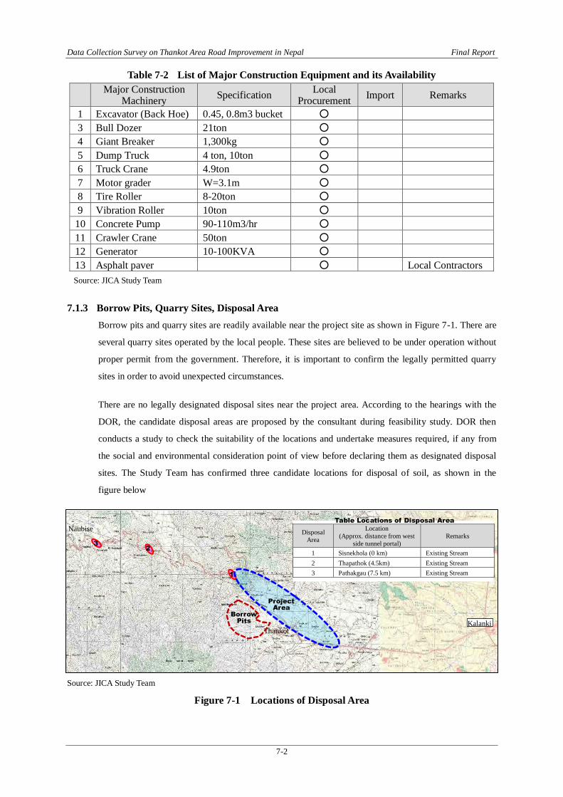
7.1.3 Borrow Pits, Quarry Sites, Disposal Area Borrow pits and quarry sites are readily available near the project site as shown in Figure 7-1. There are
several quarry sites operated by the local people. These sites are believed to be under operation without
proper permit from the government. Therefore, it is important to confirm the legally permitted quarry
sites in order to avoid unexpected circumstances.
There are no legally designated disposal sites near the project area. According to the hearings with the
DOR, the candidate disposal areas are proposed by the consultant during feasibility study. DOR then
conducts a study to check the suitability of the locations and undertake measures required, if any from
the social and environmental consideration point of view before declaring them as designated disposal
sites. The Study Team has confirmed three candidate locations for disposal of soil, as shown in the
figure below
Source: JICA Study Team
Figure 7-1 Locations of Disposal Area
Kalanki Thankot
Naubise Disposal Area
Location (Approx. distance from west
side tunnel portal) Remarks
1 Sisnekhola (0 km) Existing Stream 2 Thapathok (4.5km) Existing Stream 3 Pathakgau (7.5 km) Existing Stream
1
2 3
Table Locations of Disposal Area
Project Area
Borrow Pits

Data Collection Survey on Thankot Area Road Improvement in Nepal Final Report
7-3
7.1.4 Construction Method The construction works of the road sector will include excavation of earth, hauling, placement and
compaction of embankment materials, pavement, bridges, culverts, and other structural works and
installation of road facilities and traffic signals. To minimize the hauling of borrow materials, excavated
soil within the project shall be utilized as much as possible and the remaining volume will be hauled
from borrow pits close to the embankment site.
The proposed bridges and culverts are mostly reinforced concrete type of structures. They will be
constructed basically by cast-in-place with all staging method using falseworks and formworks. All
material, cement, reinforced bars, aggregates for concrete, bitumen, pipes etc. are available locally.
7.1.5 Capacity of Local Contractors In the last decade, considerable progress has been made in the construction of roads. Recently, there are
roads being constructed at many places. According to the Federation of Contractors Association of
Nepal, there are more than 250 contractors registered as members. Some of the contractors now have
sufficient knowledge, technology and equipment for construction of roads. However, maintaining
quality and schedule still remain as major concerns.
In 1974, The Industrial Enterprises Act, which is the first act to define ‘Contractor’ in Nepal. It made
provision for the classification and registration of contractors. According to this act all construction
firms must register themselves with the Ministry of Works and Transport in class A, B, or C contractors
depending upon the technical manpower, value and number of works done, machinery and liquid assets
available. The capacity of these contractors in terms of bidding limits is shown in Table 7-3.
Table 7-3 Bidding Limit by Classification
Classification Build Limit (1975) (Million Nepali Rupees)
Build Limit (1999) (Million Nepali Rupees)
A Above 10 Above 20
B Less than 10 Less than 20
C Less than 3 Less than 6
D Less than 1 Less than 3
Source: HP, Federation of Contractors Association of Nepal
Compared to international contractors, the level/capacity of these local contractors is relatively low. This is because the major works these contractors undertake are limited to repairs and rehabilitation and those do have experience in constructing new roads, in most cases they work as a sub-contractor.
This project is scheduled to be implemented under a consortium with a Japanese construction company. The local contractor(s) involved in this project can have technical transfer from the Japanese company in terms of quality control, schedule control and safety control and

Data Collection Survey on Thankot Area Road Improvement in Nepal Final Report
7-4
environmental mitigation measures. This will contribute in enhancing the capacity of the contractors which will be beneficial to the GON.
7.2 Construction Plan of Tunnel
7.2.1 Major Construction Material Construction material to be used for tunnel is basically concrete, shotcrete and rock bolt. However for
temporary support, H-beams will be required. The availability of the material is as shown in Table 7-1.
7.2.2 Special Construction Equipment Special equipment used for NATM is Rock Drilling Machine, Shotcrete mixing plant, Shotcreting
Machine, Side-dump Loader and Ventilation Fan. Photos 7-1 shows the equipment. These material are
neither available locally nor can be procured from India. Therefore, all these equipment are required to
be procured from Japan. The concrete lining equipment such as sliding form is also required to be
procured from Japan. In addition, the deficiency of power supply, which is evident from the everyday
load shedding in the Kathmandu Valley, necessitates some special engine air compressor also to be
procured from Japan.
(a) Rock Drilling Machine (b) Shotcrete Mixing Plant
(c) Shotcreting Machine (d) Side-dump Loader

Data Collection Survey on Thankot Area Road Improvement in Nepal Final Report
7-5
(e) Ventilation Fan
Source: JICA Study Team
Photos 7-1 Special Equipment for Tunnel Construction
7.2.3 Capacity of Contractors and Human Source Although there are a number of hydro-tunnels in Nepal, the number is nil when it comes to road tunnels.
Therefore, the contractors involved in hydro-tunnel projects might have some knowledge and experience
in the conventional method. But there are no contractors that have experience of NATM tunnels.
On the other hand, the workers involved in the construction of a tunnel needs to have knowledge and
skill to work in a narrow space and are also required to be familiar with the safety issues as it requires
blasting. Human resources with such skill and experience are hardly available in Nepal. Therefore, a
tunnel excavation team which consists of tunnel foremen, tunnel special worker, and tunnel regular
worker is desirable to be procured internationally. However, concrete lining team and other maintenance
specialists such as electrician, mechanics in addition to ordinary worker are available in Nepal.
As a mountainous country, needs for tunnels to ensure faster and safer transportation of people and
goods is expected to increase in the future. Implementation of this project can provide an opportunity to
enhance the capacity of local contractors in this field thru technical transfer on application of NATM,
quality, schedule and safety control including deformation check during tunnel excavation etc. from
Japanese contractors, which in a long run is deemed to be beneficial to Nepal.
7.2.4 Construction Yard and Water Treatment Plant An empty space available near the west side portal (exit toward Naubise) of the proposed tunnel is a
suitable candidate for construction yard. The location of the yard is shown in Photo 7-2 (a). The
treatment of drainage during excavation is easier if excavated from the west side portal. As such,
availability of a yard at this location is favorable for the construction. On the other hand, a muddy water
treatment plant is used to treat the muddy water discharged from the tunnel during construction. This
will remove the sediments and neutralize the discharged water. Photo 7-2 (b) shows the treatment plant.
Adding to the tunnel portal, about 2 ha of national forest in this area shall be cleared for the construction.

Data Collection Survey on Thankot Area Road Improvement in Nepal Final Report
7-6
(a) Location of Construction Yard (b) Muddy Water Treatment Plant
Source: JICA Study Team
Photos 7-2 Construction yard and Water Treatment Plant
7.2.5 Disposal Area Considering the excavation volume of rock material, the disposal area the volume of which is about
350,000m3 is required for the project. The disposal area of each project is indicated by DOR during the
design stage, before the start of the work.
In the region of the project, the environment team of DOR will indicate the location and appropriate
EIA is obtained when required. The candidate locations of disposal area are shown in Figure 7.1. These
areas after fill may be used for the additional lanes, for the control office of the tunnel and for the region
development program such as "Michino-Eki".
7.2.6 Lighting
The lighting of the tunnel is very important for securing traffic safety inside the tunnel. The lighting
must be planned such that both the initial cost and maintenance cost is economical. Recently, LED
lighting is in common use whose overall cost is less than the conventional lighting. Therefore, it is
recommended to use LED lightings inside the tunnel as far as possible.
7.2.7 Safety Facilities The tunnel length of 2.35km and the daily traffic of 7,500 classify the tunnel class B in Japanese road
tunnel safety standard. The class B tunnel requires provision of;
- Emergency telephone in the tunnel - Push button report facility in tunnel - Emergency alarm at the entrance of tunnel - Portable fire extinguisher in tunnel - Evacuation guide panel on tunnel wall
On the other hand, a class A tunnel that has low traffic volume, in addition to the above safety facilities,
the following facilities for safety reasons are required.
Candidate Construction Yard
Tunnel Portal

Data Collection Survey on Thankot Area Road Improvement in Nepal Final Report
7-7
- fire hydrant - evacuation route or smoke removal equipment/system (ventilation system can be designed
that will function as smoke removal system)
7.2.8 Ventilation From the tunnel length (L) of 2.35km and the recent traffic volume (N) of 7,500 per day excluding
motorbikes, the limit of the natural wind ventilation estimated, in accordance with Japanese Road
Tunnel Ventilation Standard, is as follows:
1) Design Hourly Traffic Volume in City/Rural Area and Flat Topography N= 0.090 × 7,500 = 675 vehicles per hour
2) Two (2) directions Traffic Tunnel L・ N = 675 × 2.35 = 1,586 over 1,000 Hence, Natural Wind Ventilation is not applicable, and provision of ventilation system is required. The typical ventilation by the Jet Fans will be most simple and applicable among various ventilation systems.
3) One (1) direction traffic tunnel L・ N = 666~888 < 3,000 Hence, Natural Wind Ventilation is effective up to the maximum traffic volume of the project road.
7.2.9 Power Supply Facilities One of the prerequisites in connection to the implementation of this project is assurance of power supply
and backup system. Stable and continuous electricity supply will be critically required during operation
and maintenance, particularly inside the tunnel section to keep the ventilation and lights adequately
functioning.
The total electric power demand of the tunnel will reach to 1,000 kw. Supply of this power in a stable
and continuous manner can be made available from Nepal Electric Authority (NEA). However, a minute
of understanding (MOU) has to be signed between MOPIT and MOE for this provision. This is possible
if the project road is enlisted in the National Priority Project List. The power supply line to the tunnel
from the transmission line or directly from the nearby substation of NEA needs to be maintained as well
as the provision of power supply system inside the tunnel is required.
Data Collection Survey on Thankot Area Road Improvement in Nepal Final Report
7-8
7.3 Project Cost
7.3.1 Basic Assumptions The project cost is estimated under the following assumptions;
The consultant/engineering fee (detailed design fee and construction supervision fee) is taken as 25%
of the direct cost.
The contingency fee is taken as 15% of the construction cost.
The construction of approach road (length 2.25km) including the bridges, culverts and other
structures will be undertaken by a Japanese contractor.
The construction of the tunnel section (length 2.35km) will be undertaken by a joint venture
consortium between a Japanese contractor(s) and Nepali contractor(s).
The facilities to be provided inside the tunnel are also constructed by a Japanese contractor.
The maintenance cost of the tunnel is estimated mainly based on the repair or exchange of the
equipment of the such facilities as Lighting, Safety Facilities, Ventilation and Power Supply
Facilities
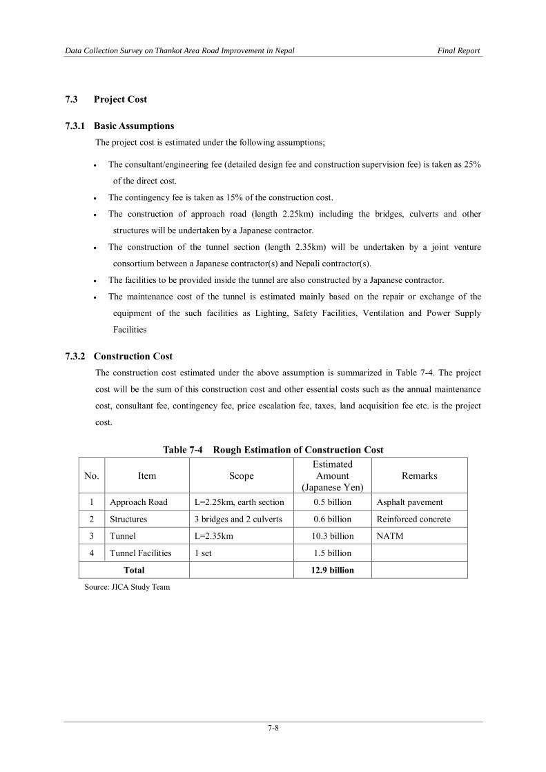
7.3.2 Construction Cost The construction cost estimated under the above assumption is summarized in Table 7-4. The project
cost will be the sum of this construction cost and other essential costs such as the annual maintenance
cost, consultant fee, contingency fee, price escalation fee, taxes, land acquisition fee etc. is the project
cost.
Table 7-4 Rough Estimation of Construction Cost
No. Item Scope Estimated Amount
(Japanese Yen) Remarks
1 Approach Road L=2.25km, earth section 0.5 billion Asphalt pavement
2 Structures 3 bridges and 2 culverts 0.6 billion Reinforced concrete
3 Tunnel L=2.35km 10.3 billion NATM
4 Tunnel Facilities 1 set 1.5 billion
Total 12.9 billion
Source: JICA Study Team
Data Collection Survey on Thankot Area Road Improvement in Nepal Final Report
7-9
7.4 Land Acquisition Cost
7.4.1 Target Area for Land Acquisition
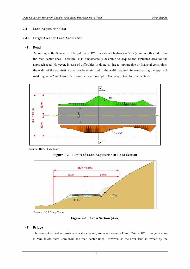
(1) Road According to the Standards of Nepal, the ROW of a national highway is 50m (25m on either side from
the road center line). Therefore, it is fundamentally desirable to acquire the stipulated area for the
approach road. However, in case of difficulties in doing so due to topographic or financial constraints,
the width of the acquisition area can be minimized to the width required for constructing the approach
road. Figure 7-2 and Figure 7-3 show the basic concept of land acquisition for road sections.
Source: JICA Study Team
Figure 7-2 Limits of Land Acquisition at Road Section
Source: JICA Study Team
Figure 7-3 Cross Section (A-A)
(2) Bridge The concept of land acquisition at water channel, rivers is shown in Figure 7-4. ROW of bridge section
is 50m (Both sides 25m from the road center line). However, as the river land is owned by the

Data Collection Survey on Thankot Area Road Improvement in Nepal Final Report
7-10
government, it is not necessary to be acquired.
Source: JICA Study Team
Figure 7-4 Limits of Land Acquisition at Bridge Section
(3) Tunnel Considering the geological condition of the portal sites, the areas recommended for the land to be
acquired are;
until the overburden of 2 times the diameter of the tunnel is secured in longitudinal direction, and
for an area where the influence line (45°+φ/2, φ: internal friction angle of soil) from the edge of the excavation width meet with the surface. (However, when the earth surface is higher than the minimum overburden height, it should be up to the point where the influence line meets with the overburden line of twice the diameter of the tunnel from the crown of the tunnel.
Source: JICA Study Team
Figure 7-5 Limits of Land Acquisition at Tunnel Portals

Data Collection Survey on Thankot Area Road Improvement in Nepal Final Report
7-11
Source: JICA Study Team
Figure 7-6 Land Acquisition in Transverse Direction
7.4.2 Land Acquisition Area Based on the explanation of Section 7.4.1, land acquisition area was calculated. The location and land
acquisition area of Alternative-C are shown in the Figure7-7.
Source: JICA Study Team
Figure 7-7 Land Acquisition Area

Data Collection Survey on Thankot Area Road Improvement in Nepal Final Report
7-12
7.4.3 Preliminary Estimation of Land Acquisition Cost As explained in Section 3.5, the preliminary unit price of the land for the Project was set as Nepali
Rupees 9,430 per square meter, based on the unit price used in the DOR F/S Report 2013, and with
comparative study of prices in classified advertisements and the governmental minimum price published
by Land Revenue Office of Kathmandu District.
Table 7-5 Samples of land prices in the Project Area Source NRs./Aana NRs./m2 Location
Unit Price used in the DOR F/S Report
2013 (p. 83) - 9,430 Between Imakhel and Sisne Khola
Land Price in Classified Advertisement,
April 2014 500,000 15,725
Swarswatisthan height, Thankot
(Residential)
375,000 11,794 Thankot (Residential)
700,000 22,015 Balambu, Behind the Nepal Telecom Station
(Residential) Source: Feasibility Study of Tunnel Roads (Nagdhunga-Naubise Tunnel Road), DOR, 2013, http://www.nepalhomesearch.com/ (Retrieved on April 18, 2014)
Table 7-6 Governmental Minimum Price in the Project Area (Kathmandu District 2013/14) Access Road Maximum Price Minimum Price
NRs./Aana NRs./m2 NRs./Aana NRs./m2
1. Main Tribhuvan Highway 320,000.00 10,064 170,000.00 5,347
2. Black topped sub- road 170,000.00 5,347 60,000.00 1,887
3. Earthen Road 100,000.00 3,145 30,000.00 944
4. Trail only 88,000.00 1,384 15,000.00 472
5. Other (Out from road touch) 32,000.00 1,006 10,000.00 315
Source: Lowest land price evaluation booklet, Land Revenue Office, Kalanki, Kathmandu, Department of Land Reform and Management, Ministry of Land Reform and Management, 2013/2014
Using the Unit Cost, the Land Acquisition Cost is calculated as follows.
Table 7-7 Preliminary Estimation of Land Acquisition Cost for 50 m ROW Area for Acquisition
m2 Unit Price
NRs. Land Cost Total
NRs. Approach Road and Tunnel Portal 120,000 9,430 1,132,000,000
Soil Disposal Area 15,000 9,430 141,450,000
Total 1,273,450,000
Source: JICA Study Team

Data Collection Survey on Thankot Area Road Improvement in Nepal Final Report
7-13
Source: JICA Study Team
Locations of Disposal Area (Already shown on Figure 7-1)
7.5 Preliminary Estimation of Resettlement Impacts The 50 m ROW alignment affects structures in mainly 7 places as indicated in Figure 7-8.
Source: JICA Study Team
Figure 7-8 Locations of the Structures to be Affected within 50 m ROW
1 2
3
4 5
6
7
Kalanki Thankot
Naubise Disposal Area
Location (Approx. distance from west
side tunnel portal) Remarks
1 Sisnekhola (0 km) Existing Stream 2 Thapathok (4.5km) Existing Stream 3 Pathakgau (7.5 km) Existing Stream
1
2 3
Table Locations of Disposal Area
Project Area
Borrow Pits

Data Collection Survey on Thankot Area Road Improvement in Nepal Final Report
7-14
Preliminary count of the structures to be affected was conducted as shown on Table 7-8.
Table 7-8 Preliminary Count of the Structures to be Affected within 50 m ROW Date: February 2014.
Area: Within the 50 m ROW
Number of counted structures: 27 (out of 27, 3 are solely used for businesses)
Estimation method of the number of residents:
(1) 15 structures (15/27=56%) were interviewed to confirm the number of the residents.
(2) For the remaining 12 structures (44%), the number of the residents are estimated.
<Estimation method> 1) Household is defined as a group of people who shares one
cooking stove. 2) In a large house with more than two stories, different
household occupies each floor. 3) The average size of one household is 4.63 as the average of
Kathmandu District. Estimated number of the residents to be resettled
36 households, 160 persons. 5 business entities.
In summary, there are 27 structures within the 50 m ROW, 24 are residential, and the number of
households and people who may need to resettle is estimated as 36 households with 160 persons. Also, 5
structures are for business use, including one brick kiln management compound. These structures and
the number of residents is listed in Table 7-8, while the structures are depicted in Figure 7-9.
Other cost for asset compensations, including lighter structures and properties, and resettlement
assistances are to be surveyed. According to DOR/GESU, the cost for asset compensations and
resettlement assistances shall be smaller compared to the cost for land acquisition.
Potential impacts at the proposed disposal sites shall also be studied in the EIA Survey.
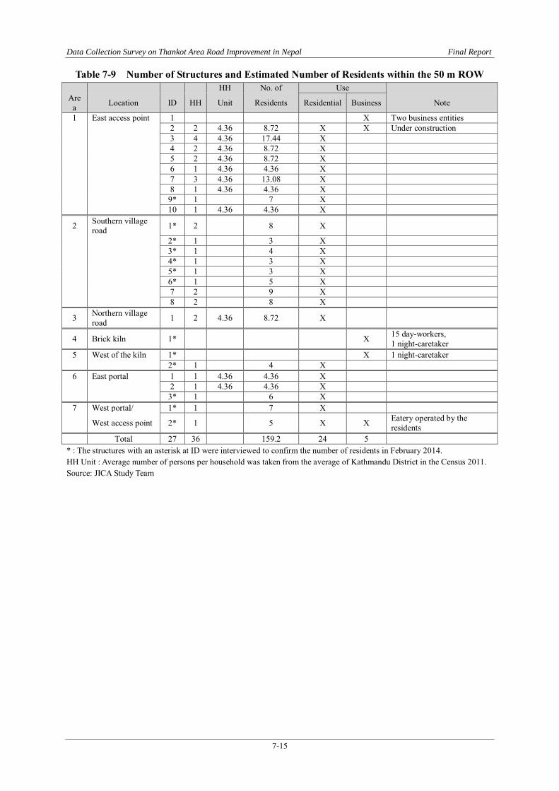
Data Collection Survey on Thankot Area Road Improvement in Nepal Final Report
7-15
Table 7-9 Number of Structures and Estimated Number of Residents within the 50 m ROW
HH No. of Use Area Location ID HH Unit Residents Residential Business Note
1 East access point 1 X Two business entities 2 2 4.36 8.72 X X Under construction 3 4 4.36 17.44 X 4 2 4.36 8.72 X 5 2 4.36 8.72 X 6 1 4.36 4.36 X 7 3 4.36 13.08 X 8 1 4.36 4.36 X 9* 1 7 X 10 1 4.36 4.36 X 2 Southern village
road 1* 2 8 X 2* 1 3 X 3* 1 4 X 4* 1 3 X 5* 1 3 X 6* 1 5 X 7 2 9 X 8 2 8 X 3 Northern village
road 1 2 4.36 8.72 X
4 Brick kiln 1* X 15 day-workers, 1 night-caretaker
5 West of the kiln 1* X 1 night-caretaker 2* 1 4 X 6 East portal 1 1 4.36 4.36 X 2 1 4.36 4.36 X 3* 1 6 X 7 West portal/ 1* 1 7 X West access point 2* 1 5 X X Eatery operated by the
residents Total 27 36 159.2 24 5
* : The structures with an asterisk at ID were interviewed to confirm the number of residents in February 2014. HH Unit : Average number of persons per household was taken from the average of Kathmandu District in the Census 2011. Source: JICA Study Team

Data Collection Survey on Thankot Area Road Improvement in Nepal Final Report
7-16
Figure 7-9 Residential Structures within the 50 m ROW Area/ Location ID Photo ID Photo
1 East access point 1
2
3
4
5
6
7
8
9
10

Data Collection Survey on Thankot Area Road Improvement in Nepal Final Report
7-17
Area/ Location ID Photo ID Photo
2 Southern village road 1
2
3
4
5
6
7 (No photo) 8 (No photo)
3 Northern village road 1
4 Brick kiln 1

Data Collection Survey on Thankot Area Road Improvement in Nepal Final Report
7-18
Area/ Location ID Photo ID Photo
5 West of the kiln 1
2
6 East portal
1
2
3
7 West portal/West access point 1
2
Source: JICA Study Team

Data Collection Survey on Thankot Area Road Improvement in Nepal Final Report
7-19
7.6 Legal and Administrative System Necessary for Tunnel Construction and Safeguard
7.6.1 Purpose Land use above the tunnels need to be monitored and restricted to safeguard the structures. For example,
a deep well boring or very heavy structure on soft or fragile soil may affect the stability of tunnel
structures.
7.6.2 Target Area In Japanese Design Standard, tunnel easement area is defined as follows.
In land use restriction areas, it covering a distance of 1D from the edge of the tunnel in all directions should be designated the protected area of tunnel.
The area where the height of the overburden is less than 10m is subject to acquisition.
Source: JICA Study Team
Figure 7-10 Tunnel Profile Showing the Section of Necessary Land Use Restriction
Source: JICA Study Team
Figure 7-11 Cross Section of Protected Area (A-A)
A
A

Data Collection Survey on Thankot Area Road Improvement in Nepal Final Report
7-20
7.6.3 Activities Necessary to be Restricted Land owner in the Tunnel Easement, public or private, shall be subject to following restriction in their
activities.
Table 7-10 Activities to be Restricted and not Restricted in the Tunnel Easement
Building Activities Excavation Activities
RESTRICTED
(Need monitoring)
1. New construction of building that exceed the existing size or design
2. Total or partial renewal of building to exceed the existing size or design
3. Boring, excavation, or clay collection that reach the depth of the PROTECTED AREA
NOT Restricted
4. Use of existing building
5. Total or partial renewal of building that does not exceed the existing size or design
6. Use of existing water wells
7. Boring new wells that does not reach the depth of the PROTECTED AREA
8. Excavation or clay collection that does not reach the depth of the PROTECTED AREA
Source: JICA Study Team
7.6.4 Legal and Administrative System Necessary
(1) Legal base In Nepal, land use restriction under the electricity transmission lines has already been made legal by the
Electricity Regulation 2050 (1993). It is desirable to prepare similar legal base for the land use
restriction in the Tunnel Easement.
Table 7-11 Linear Infrastructures and Safeguard Actions in Nepal Example Administration Easement/Restriction Legal Base
High Voltage Electricity Transmission Line
Nepal Electricity Authority
Height and width clearance from the center of the transmission line is defined.
Basically, the land under the line may be used for crop farming, but construction of structures shall be restricted.
The Compensation Determination Committee orders the NEA to pay certain percentage of the land value to be affected to the land owner.
The percentage differs depending on the severity of the impact, but in general between 10 to 25 % of the land value of the affected area.
Electricity Regulation 2050 (1993)1
Hydropower Plant Water Tunnel N/A
Most part of the water tunnels pass through national forests without road access.
No urban development is expected above the tunnels.
Therefore, no tunnel easement has been considered so far.
N/A
Source: JICA Study Team
1 Source : Nepal Electricity Authority, http://www.nea.org.np/images/supportive_docs/Electricity_ Regulation_2050-english.pdf (Retrieved on April 4, 2014) The contents of Schedule 12 differs from the results of the interview. The amended, newest version of the regulation must be cited in the later phase of the Project.

Data Collection Survey on Thankot Area Road Improvement in Nepal Final Report
7-21
In Japan, the area of tunnel easement is made public as a part of City Plan or Land Use Plan. Those who
apply for legally required construction permission are instructed by municipality staff about acceptable
and non-acceptable activities.
Since such land use plan or construction permission system do not exist in the Project Area, the control
power specific for road tunnels, at least in the starting phase, shall better be held by DOR or MOPIT.
In near future, similar legal safeguards shall become necessary for underground facilities related to
electricity, drinking water, and sewerage in Municipalities in Nepal.
Table 7-12 Excerpts of Electricity Regulation 2050 (1993)
CHAPTER 5 SAFETY MEASURES REGARDING ELECTRIC DEVICES
48. Minimum Distance from Ground to the Electric Wire: (1) Distance between the electric wire of different
volts of the distribution and transmission system and the ground shall not be less than as prescribed in
Schedule 12.
(2) In case where electric line is to be installed by the side of the road or along it, it shall be done by adopting
appropriate technological measures.
(3) If it is necessary to install electronic line of more than 33,000 volts, it shall have to be done by adding
0.305 meter for each 33,000 volts on the distance as prescribed for 33,000 volts in Schedule 12.
49. Regarding the Installation of Electric Line Across the Road: While installing electric line of more than
211,000 volt across the road in a densely populated area, the double insulator system shall have to be used.
50. Distance to be Maintained on either side of the Electric Line: (1) While installing electric line of
distribution and transmission system, it shall not be installed in a distance lower than the distance as
prescribed in Schedule 13 from the house or tree.
(2) If it is necessary to install electric line of more than 33,000 volt, it shall have to be done by adding 0.305
meter for each 33,000 volts on the distance as prescribed for 33,000 volts in Schedule 13.
Schedule 12 (Relating to Rule 48) Distance which ought to be from wire to the ground
S. No. Standard of voltage of electricity
While crossing the road (m)
On the side of the road (m)
In other places (m)
1 In between 230/400 and 11,000 5.8 5.5 4.6 2. In between 11,000 and 33,000 6.1 5.8 5.2
Schedule 13 (Relating to Rule 50) Minimum distance which ought to be from the wire to the house or
tree. S. No. Standard of Voltage of Electricity Minimum Distance to be from house or tree
1. Standard 230/400 to 11,000 1.25 meter 2. From 11,000 to 33,000 2.00 meter Note: While determining the minimum distance as above maximum deflection of wire
arising due to air pressure shall also have to be considered. Source: Nepal Electricity Authority, http://www.nea.org.np/acts-regulations.html (Retrieved May 9, 2014)

Data Collection Survey on Thankot Area Road Improvement in Nepal Final Report
7-22
(2) Monitoring The necessary tunnel easement and related restrictions must be explained to the related land owners and
other stakeholders well before the implementation of the restrictions.
In the operation phase of the tunnel, continuous patrol and monitoring activities are necessary to prevent
any breach of the restriction, until the system for building construction permit become popular in the
Project Area. Since the legal base is expected to reside with DOR or MOPIT, the responsibility of the
patrol and monitoring shall also be bore by those, most probably DOR Division Office, which is
currently hiring the daily maintenance workers on National Highways.
Kathmandu Metropolitan City is already administrating the building construction permit. In the long
term, such governmental control is expected to be popular and mandate for all the area in Kathmandu
District.
(3) With or without compensation The Japanese Land Acquisition Ordinance for Public Works states that when the use of underground
space restricts the surface use, the Project Owner shall compensate depending on the significance of the
restriction.
Therefore, when tunnel is very deep and no restriction is expected for the surface use, or when the area
is very remote and no urban development is expected, the Project Owner, with the consent from land
owners, shall be waived from compensation.
In Nepali condition, the land acquisition procedure led by the CDC is well known and generally
accepted by the society. Using this existing social system in the Project regarding the tunnel easement
may help smooth promotion of the Project.

Data Collection Survey on Thankot Area Road Improvement in Nepal Final Report
8-1
Chapter 8 Operation and Maintenance Plan
8.1 Operation and Maintenance Plan of Road
8.1.1 Existing Maintenance System
(1) Responsible Organization The organization responsible for maintenance of roads and bridges for the Strategic Road Network is the DOR. Other organizations are Municipalities for municipality roads and District Development Committees for district and agricultural roads. The maintenance of the study road is responsibility of the DOR. The organization responsible for financing is Roads Board Nepal (RBN) and DOR. RBN also conducts monitoring and evaluation of road maintenance works executed by road agencies through outsourcing to local consultant as it has limitations from the size of the RBN Secretariat.
1) Department of Roads The Department of Roads is the agency that is responsible for repair and maintenance of the roads in the SRN. These roads are consisted of highways and feeder roads. The Maintenance Branch directly under the DG undertakes the maintenance activities. However, the actual works are conducted by the Division Offices under the Regional Directorate. There are 5 regional directorates; i) Eastern, ii) Central, iii) Western, iv) Midwestern, and v) Far western, and 25 division offices.
The maintenance within the stretch of the study road (Kalanki to Naubise) is presently being undertaken by two divisional offices under the Central Regional Road Directorate (CRRD). The section within Kathmandu District (Kalanki to Nagdhunga) is looked after by Kathmandu Division and the stretch beyond that is looked after by Bharatpur Division.
2) Roads Board Nepal Roads Board Nepal (RBN) was established under the Roads Board Act 2058 (2002). It has been established to carry out the routine, recurrent, periodic and emergency repair and maintenance of the road and make arrangement for imposition on and collection of toll from the motor vehicles plying on the road for maintenance purpose. Its present source of revenue and other possible resources yet to be tapped are as follows;
Present Resources
・ Fuel levy on diesel and petrol for vehicles ・ Toll collections (collected at three stretches; Naubise-Mugling on Tirbhuvan Highway,
Narayanghat-Hetauda and Narayanghat-Butwal on East-west Highway)
・ Vehicle registration fees

Data Collection Survey on Thankot Area Road Improvement in Nepal Final Report
8-2
Resources to be tapped
・ Fee for vehicles registered abroad but used in Nepal, ・ Subsidies and grant from GoN and support from donors and internationals
The collected fund in RBN account is mobilized through DOR for maintenance of SRN and through DoLIDAR to concerned Municipalities and District Development Committees (DDC) for urban, district and agricultural roads. 70% of the fund is allocated to the maintenance of the SRN and remaining 30% to the maintenance of LRNs. However, the road agencies have to provide a minimum committed counterpart fund of 30% for Municipalities and 20% for the DDC’s from its portion.
The revenue collected from fuel levy and vehicle registration tax and the actual budget allocated to RBN from MoF for the last 5 years is listed in Table 8-1. Similarly, the toll collection for a period of fiscal year 2065/66 to 2067/68 is shown in Table 8-2.
Table 8-1 Budget of Roads Board Nepal for the previous 5 years (Figures in Thousand NRs.)
Fiscal Year
Collection from NOC & DOTM Sub-Total
(NOC+DOTM)
Actual Budget
Allocated (MoF)
Deficit as per collection
Fuel Levy Vehicle
Registration
2065/66 (2008/09) 741,108 688,439 1,429,547 664,500 765,047
2066/67 (2009/10) 926,556 1,458,641 2,385,197 1,314,500 1.070,697
2067/68 (2010/11) 1,758,821 1,597,623 3,356,444 2,518,000 838,444
2068/69 (2011/12) 2,097,860 1,439,784 3,537,644 2,768,000 769,644
2069/70 (2012/13) 2,332,714 2,572,775 4,905,490 2,573,700 2,331,790
Source: Roads Board Nepal (RBN)
Table 8-2 Amount of Toll Collected in the Period of 2065/66 – 2067/68
Toll Roads Collected Amount in Fiscal Years (in thousand NRs.)
2065/66 (2008/09) 2066/67 (2009/10) 2067/68 (2010/11)
Naubise-Mugling 28,937 36,274 36,817
Hetauda – Narayanghat 19,660 15,704 24,821
Narayanghat - Butwal 16,284 117,693 15,099
Total 64,881 69,671 76,737
Source: Annual Progress report 2067/068, Roads Board Nepal (RBN)
The figures in both the tables show increment every year. In connection with the budget, there was a significant increment fiscal years 2009/10 and the following year. Yet, there is no controversy that the budget for maintenance is not enough to address all the maintenance work required.

Data Collection Survey on Thankot Area Road Improvement in Nepal Final Report
8-3
(2) Types of Maintenance and Funding The maintenance of a roads and bridges is divided into the following categories.
1) Routine Maintenance Maintenance activities carried out routinely and continuously in order to prevent the damage to road pavement and other ancillary structures due to environmental effects.
2) Recurrent Maintenance All scale maintenance activities, which are carried out recurrently at different times in a year in damaged road surface/pavement due to traffic pressure/load from vehicles plying on roads.
3) Periodic Maintenance This is defined as large scale maintenance of road surface/pavement, which should be carried out at a given interval of defined number of years.
4) Emergency Those maintenance activities which are carried out in case the traffic is disrupted and road closed due to any type of unexpected damage on the roads.
5) Rehabilitation, Reconstruction and Upgrading These maintenance works are those works that have exceeded the limits of periodic maintenance. In other words, all those roads that are no more maintainable and needs an overall repair to revive the expected function is defined here.
Routine, recurrent, periodic and emergency repairs and maintenance is financed by RBN. However, limited financial grant is allocated for other higher category of maintenance works such as rehabilitation, reconstruction and upgrading. Only when the resource remains surplus after allocating funds for priority or pre-determined maintenance works will this category be considered. Other maintenance categories are financed by the responsible authorities.
(3) Maintenance Procedure A simplified maintenance procedure is shown in Figure 8-1 and summarized below.
i) Road agencies prepare and submit annual road maintenance plan to RBN. DOR prepares for highways and feeder roads in the SRN and DoLIDAR and VDCs prepare for local and agricultural roads.
ii) Upon receiving ARMPs from DoR and DOLIDAR, RBN prepares integrated annual plan by end of Shrawan, the first month of a fiscal year (mid-August).
iii) Regarding road rehabilitation, reconstruction, upgrading and road safety, RBN may

Data Collection Survey on Thankot Area Road Improvement in Nepal Final Report
8-4
prepare and implement a periodic integrated plan for either 3 or 5 year period. ( Provision of periodic annual plan)
iv) After reduction of administrative amount from the budget, 70% of the remaining budget is allocated to maintenance and 30% to other works related to maintenance.
v) Demand for allocation of emergency fund, if any be DOR to RBN..
vi) As a contribution to maintenance resource, concerned local agencies allocate certain amount. DDC minimum 20% and Municipalities minimum 30%
vii) Selection of roads for rehabilitation and reconstruction is made based on priorities. National highways and feeder roads have top priority.
viii) In case extra fund is available, upgrading of existing roads is funded but with the provision that allocation for such upgrading does not exceed 15% of total revenue
Source: JICA Study Team
Figure 8-1 Procedure of Maintenance
8.1.2 Proposed Maintenance Plan No new plans for establishing an organization or procedure for the maintenance of the road section including structures of the proposed route is required.
However, as the present maintenance system is not able to fully address the maintenance issues of entire roads of the country, it is necessary that the project road be classified into the top
Preparation of Annual Repair and Maintenance Plan (ARMP)
Road Agencies (DOR/DoLIDAR)
PLAN
ALLOCATE
IMPLEMENT
Provision of Periodic Annual Plan
Integrated Annual Plan
RBN
・ Rehabilitation, Reconstruction and Upgrading
・ Demand for Emergency Allocation
・ Counterpart Fund by Local Agencies (DDCs 20%, MU 30%)
・ Resource Allocation (maintenance 70%, others 30%)
・ Resource Allocation (selection for rehabilitation, reconstruction)
・ Upgrading not exceeding 15% of total amount
・ Implementation ・ Supervision
・ Reporting ・ Evaluation

Data Collection Survey on Thankot Area Road Improvement in Nepal Final Report
8-5
priority road so that the maintenance work of the road is more attentively addressed and emphasis is given to allocation of budget for sustainable maintenance.
8.2 Operation and Maintenance Plan of tunnel
8.2.1 Existing Organizations and Plans There are no road/highway tunnels in Nepal. Therefore, no organization has ever been established for any kind of work in connection with the road/highway tunnels.
8.2.2 Proposed Maintenance Plan
(1) Operation and Maintenance Organization The organization responsible for operation and maintenance of the tunnel is suggested to be a division office under Regional Road Directorate. Considering the location of the proposed route, Kathmandu Division Office under the Central Regional Road Directorate (CRRD) is deemed optimal candidate. Furthermore, being the first possible road tunnel in Nepal, which will require a new and different approach for operation and maintenance compared to that of a road, it is recommended the a special unit should be set up and entrusted all the task under stringent monitoring from the CRRD. The recommended aims and duties of the organization will be but not limited to;
1) Maintenance of the tunnel - monitoring the traffic - maintaining the tunnel facilities - maintaining the tunnel structure
2) Control the fire and accidents and to avoid disaster - recognizing the condition - communicating and cooperating rapidly with relative organizations (fire station, traffic
police) - announcing to the public
Although the main responsible organization for the operation and maintenance is the DOR, close coordination with the police, fire department, hospital etc. will be required during disasters. Therefore, the responsibility of each relevant authority should be made clear and a communication system between these authorities should be established when preparing the maintenance plan.
8.2.3 Operation and Maintenance Systems In order to operate and maintain the tunnel structures, facilities and safety, the following maintenance systems are required and recommended in the office of the organization;

Data Collection Survey on Thankot Area Road Improvement in Nepal Final Report
8-6
- Tunnel Operation and Monitoring System - CCD TV Monitoring System - Emergency Notification System
(1) Tunnel Operation and Monitoring System The system will consists of the data transfer equipment at tunnel entrance and the data monitoring equipment at the office of the organization. The data, which show how the lighting, ventilation and safety facilities are working, will basically be transferred to the receiver and monitored by the office of the organization by cell phone system. The emergency data, which come from the emergency telephone, emergency push button and emergency alarm signal, will also be transferred to the office by cell phone system in case of accident and/or fire, in order to enhance on time and speedy communication with relative organization to prevent a major disaster.
(2) CCD TV Monitoring System Provision of TV cameras for the purpose of safety inside the tunnel is not required by the Japanese Standard. However, this can enable visual monitoring of traffics for obtaining prompt and reliable information of traffic condition inside the tunnel. Being the first tunnel for DOR, Provision of such system is instrumental and is thus recommended to be installed.
(3) Emergency Notification System The emergent information such as accident and fire in the tunnel had better be notified to the public. In addition to the traffic condition in the tunnel, the emergent information can be provided to smart phones form web-site of the Operation and Maintenance Organization by this system.
8.2.4 Recommended Additional Support
(1) Disaster Prevention Program with Operation Training This program aims to contribute to the staffs of operation and maintenance organization (special unit) to recognize the significance of the disaster in and around the tunnel and to minimize the cause and effects of accident and fire in the tunnel, based on the past experiences and the prevention/minimization of the disaster methods practiced in Japan. This may also include the lecture of the actual activities which the staff of the Organization should take and the operations of the Systems above.
This support may be provided by the consultant as soft component to the organization responsible for maintenance of the tunnel in the after completion of installment of the maintenance and operation systems and prior to commencement of service to the public.
(2) Procurement of fire engine
Data Collection Survey on Thankot Area Road Improvement in Nepal Final Report
8-7
Fire stations exist only in the Municipalities. The nearest fire station from the project site is the one in Kathmandu or Lalitpur Municipality, both in an approximate distance of 10km. Accidents inside tunnels sometimes cause fire and could be very fatal. Therefore, it is very important to assure availability of fire engines in such cases. The Study Team recommends provision of a fire station near the proposed tunnel. As the proposed tunnel is about 2km long, it is desirable to have such facilities at both sides of the tunnel. One method to procure fire engines could be from the Japanese Assistance through a technical cooperation project.
This support may be achieved by provision of fire engine (new or used). The engines those are procurable from Nepal are suggested to be procured as a part of cooperation of Japan such as under a grass-root scheme and grant to the concerned organization for use during disasters.
8.3 Maintenance of Structures
8.3.1 General The maintenance of the structure needs to be operated in accordance with the maintenance guidelines established. The operation of the maintenance work should be performed in accordance with relative rules and laws, and the safety of the passengers and the workers must be well examined under careful consideration.
8.3.2 Cleaning The Cleaning of the tunnel needs to be operated effectively and efficiently as planned, considering the condition of the dirt and the traffic. The periodical cleaning should be performed in principal.
8.3.3 Road Surface The condition of the road surface needs to be constantly checked visually. When any unusual matters are observed, the appropriate prompt actions should be taken.
8.3.4 Lining The condition of the lining needs to be checked constantly. When unusual matters such as cracks, leakage of water or other disorders are observed, the appropriate prompt measures should be taken promptly and adequately.
8.3.5 Safety Facilities The safety facilities need to be checked and maintained in order to demonstrate the sufficient abilities to control the fire and accidents inside the tunnel.
8.3.6 Lighting Facilities The lighting facilities needs to be checked and maintained, in order to maintain the safe and smooth visibility in the tunnel, particularly during night time as the road has traffic volume at

Data Collection Survey on Thankot Area Road Improvement in Nepal Final Report
8-8
night time almost equal to the traffic volume of the day time. The maintenance of the lighting facilities will include checking, cleaning, repairing, replacing and recording.
8.3.7 Ventilation Facilities The ventilation facilities of the tunnel needs to be checked and maintained constantly, including the reactive function of the relative machines, meters and so on.
8.3.8 Electricity Supply The electricity for the tunnel facilities needs to be obtained from Nepal Electricity Authority (NEA). However, according to the results of the hearings conducted with the NEA official, it is necessary that the proposed road be designated as the National Priority Project and a memorandum of understanding (MOU) be signed between MOPIT and MOE, which will make DOR eligible for receiving stable and continuous electricity supply from NEA.
8.4 Maintenance Resource The maintenance cost is required for the periodic exchange and repair of the equipment of the electrical and mechanical facilities. As mentioned before, the routine, recurrent, periodic and emergency maintenance is financed by RBN. There is no controversy that the budget for maintenance is not sufficient. Under such circumstances and conditions, there is no guarantee that these works will be covered by the RBN budget. Therefore, one of the most important responsibilities of the newly established operation and maintenance organization (special unit) is to make arrangements and plan for allocation/securing of maintenance budget. It is also desirable that the organization make effort to ascertain that the proposed road is designated as the national priority project so that it could be entitled as top priority road for maintenance. Therefore, further study and investigation is deemed necessary on determining the specific method for allocation of the required budget.
8.5 Maintenance Cost (1) Routine maintenance cost
One main maintenance cost is required for the repair/change of the equipment of lighting and safety facilities as short/medium term periodic maintenance due to the lifetime of the equipment. This is estimated at about 4 million NRs in annual average.
(2) Periodic maintenance cost The other main maintenance cost is Periodic required for the renewal of the ventilation and electric supply systems as long term maintenance due to the lifetime of the system and for the pavement overlay. This is predicted about 400 million NRs in 50 years in total.

Data Collection Survey on Thankot Area Road Improvement in Nepal Final Report
9-1
Chapter 9 Environmental and Social Considerations
9.1 Summary of Scoping of Impacts based on the JICA Guideline
9.1.1 Title of the Project Thankot Area Road Improvement
9.1.2 Outline of the Project
Issue Condition Original Reference
Project Sector: Road, with short bridges
Scale of the project:
(1) Approach road (surface) : Length 2,250 m, width (ROW) 50 m.
(2) Tunnel road : Length 2,350 m, width (excavation) 13 m (3) Soil disposal : 350,000 m3
(1)(2) Table 5-4.
Alternative C
(3) 7.2.5
Cost for land acquisition
(1) Road : 1,132 million NRs. (2) Soil disposal : 141 million NRs. (15,000 m2) (3) The unit cost, 9,430 NRs/m2, was taken from the DOR
Feasibility Study Report, 2013. The number was authorized as realistic price for project formation.
7.4.3
Compensation Determination Committee, established based on Land Acquisition Act, shall conduct survey of recent transactions and determines the price of land. The project owner shall follow the decision.
The governmental minimum price in the Project Area varies between 315 to 10,064 NRs/m2, depending condition of road access.
Advertised prices on internet varied 11,794 to 22,015 NRs/m2 in April 2014.
The unit cost is considered rational because it is close to the advertised prices and far larger compared to the governmental minimum price.
Other cost for asset compensations and resettlement assistances
To be surveyed. DOR/GESU explained that the cost shall be smaller compared
to the cost for land acquisition. 7.5
Name of Project Execution Organization:
Department of Roads, Ministry of Physical Infrastructure and Transportation
Address of the project site:
Kathmandu District (Mahadevsthan, Dahachok, Thankot, Baad Bhanjyang VDCs) Dhading District (Naubise VDC)
Source: JICA Study Team
9.1.3 EIA status Issue Condition Additional Information
EIA Status Based on the Nepal Laws and Regulations Required (Under planning)
Full EIA and approval of MOSTE for new construction of National Highway
Status of other necessary environmental permit(s) Required but not obtained yet.
Name(s) of required permit(s):
Forest clearance permission from Ministry of Forest and Soil Conservation
Source: JICA Study Team

Data Collection Survey on Thankot Area Road Improvement in Nepal Final Report
9-2
9.1.4 Environmental Categorization According to the JICA Guideline and Reasoning
(1) Category Category B
(2) Reasoning The project is to construct about 5 km bypass of existing National Highway in the suburb of the Kathmandu Capital Area. The Project Area does not include or near the Protected Areas. The negative impacts during the construction and operation phases will be limited to the area in and along the work areas. The number of project affected people who are expected to resettle is 160. The other impacts are not to surpass the severity or size of what is observed along the existing Highway.
The bypass road will stay in the area permanently and its impacts will stay in the area. Therefore it is reasonable to categorize the Project in Category B.
Differences between Categories
Category Severity Uncertainty Size of the Impact Irreversibility Transboundary
A
The negative impacts are severe on environment and social condition.
The negative impacts are complicated or unprecedented, and the prediction and management of the impacts are difficult.
The negative impacts from the project affect large population or large area, or long period of time.
Most of the negative impacts are irreversible.
Negative impacts affect outside of the site, and work areas, and reaches far beyond.
B
Compared to the negative impacts from the Category A project, the impacts are not severe.
Negative impacts can be avoided, minimized, or mitigated using already known measures.
Compared to the negative impacts from the Category A project, they affect small population or small area, or short period of time.
Irreversible negative impacts are small.
Negative impacts affect only on site and neighboring area.
C No negative impacts or minimum negative impacts are expected for environment and society. Source: JICA Study Team

Data Collection Survey on Thankot Area Road Improvement in Nepal Final Report
9-3
9.1.5 Outline of the Project and Project Area
Issue Condition Additional Information Reference in this Report
Environmentally sensitive area in and around project site
(1) No protected forests and conservation areas are located within or near the Project Area. (2) During the interviews with MOSTE, MOFSC, Department of Forests, Kathmandu District Forest Office, and Forest Ranger Points in Kathmandu District, potential occurence of endangered species in the Project Area was denied except Simal trees (Bombax ceiba), which is located a few places along the existing highway, but not in the work areas of the Project.
(1) The distance to the nearest Conservation Area is more than 2 km, and it is located in different watershed. (2) Red List of Nepal (IUCN, 2012), CITES-List of Animals and Plants in Nepal (CITES, 2012), and the National Parks and Wildlife Conservation Act, 1973, either do not include information of habitat locations for the listed species, or states that Kathmandu Valley is included in the habitats of mammals such as Himalayan Black Bear and Leopard. During the field survey of the EIA Study of the Project, in future phase, it is expected to clarify the occurrence or non-occurrence of those listed species in the Project Area.
(1) Figure 3-24 (2) 3.5.3
Sensitive elements
(1) Involuntary resettlement : YES. Number of resettlers : 160 persons, 36 households.
(2) Pumping of groundwater : No (3) Land reclamation and/or
development : No (4) Deforestation : Clearance of
existing forest. about 2 ha
(1) 7.5 (4) 7.2.4
Socially and economically vulnerable population to be affected
To be surveyed in the next phase of the Study.
During this Study, DOR/GESU and MOSTE (EIA) confirmed that no significant accumulation of those population is expected in the Project Area.
DOR/GESU explained that the cost for assistance for those population shall be smaller compared to the cost for land acquisition.
In the next phase of the Study, 1) interviews to the affected VDC Secretaries, 2) public consultations, 3) census survey of the households within the ROW shall be conducted to clarify the existence and needs of socially and economically vulnerable population to be affected.
VDC-wise, about 30 % of the population belong to Dalit or indigenous group. The same is expected in the Project Area.
9.7
Source: JICA Study Team

Data Collection Survey on Thankot Area Road Improvement in Nepal Final Report
9-4
9.1.6 Gaps between JICA and GON Resettlement Policy Gaps listed in the M/M dated April 17, 2014
Key Policy Gaps
JICA Guideline (World Bank
O.P.4.12) Government Laws Typical operation of DOR based on
ESMF Remaining GAP and/or
survey
Compensation Principle
All the compensation is based on the principle of replacement cost
Compensation rate will be determined by CDC, consisting of CDO,(ii) representative from DDC (iii) Chief of Land Revenue Office (iv) Project Manager, (Land Acquisition Act Clause 13) The Land Acquisition Act 1977, also mention the need of considering periodic circulations issued by the GoN while fixing compensation for the affected assets (Land Acquisition Act Clause 16)
DPs are allowed to take salvaged materials. CDC will make final decision on the compensation rates after viewing and verification of affected.
1) Whether the provisions be made for the replacement cost for the loss of land, houses/ structures by CDC is under survey.
2) There is no official
license for real estate appraiser/valuer for land, houses/ structures. Most transactions are conducted face to face of selling and buying side. Real estate broker industry is not licensed without any common professional rules. How to determine rational replacement cost is under survey.
Compensation for
Non-titleholders
Squatters/ vulnerable encroachers/non- title holders are entitled to the payment for affected structures/ houses/ business/ crops, trees, and other assistance
Do not consider squatters/ encroachers/ non-titled land users for compensation
ESMF (p. 7-9, 10) provides encroacher/ squatter and non-registered tenant/renter/lease holder does not qualify for compensation for land losses; however they will be entitled to compensation for crops, and compensation for full or partial loss of house and other structures at full replacement cost of materials and labor according to house/structure type, with no deduction for depreciation. Every displaced household will receive transportation allowance on actual cost basis.
None. (Refer 9.3 of this report)
Relocation Assistance
A all the eligible DPs including tenants, employees are entitled to receive financial assistance to cover physical and economical displacement
LA Act Clause 16-2 provisions to consider extent of losses caused due to relocation/ shifting of Displaced people, while fixing the compensation rate (LA Act Clause 16-2.
ESMF (p. 7-11) provides Displacement Allowances; 1) each displaced household will receive equivalent to 2 months poverty line income, 2) Renters will receive 35 days notice or rental stipend equivalent to 0.5 month poverty line income plus transportation assistance; 3) every household of displaced businesses will be entitled to a business displacement allowance for loss of commercial establishment.
None. (Refer 9.3 of this report)
Income Restoration
Income restoration program such as training and other measures to restore and improve the standard of living of the displaced households of those having more than 10% of the total landholdings and income
Apparently, the Land Acquisition Act 1977, do not consider for income restoration.
ESMF (p. 7-11, 12) requires assistance with training in life skills, preferential access to road construction employment for 1) households/APs having significant impacts, 2) households of the vulnerable categories, 3) APs family members over 16 years of age.
None. (Refer 9.3 of this report)
Source: JICA Study Team

Data Collection Survey on Thankot Area Road Improvement in Nepal Final Report
9-5
9.2 Laws, Rules and Standards Following table is the list of laws, guidelines and reviewing institutions the Project need to consult with. For EIA review procedure, both the EPA/EPA of MOSTE and the ESMF of DOR/GESU shall be the legal base. For detailed technical guidance of EIA survey and review procedure, the ESMF shall be the main resource.
Table 9-1 National laws and others Related to Environmental and Social Impacts Control Topic Name of Laws and Regulations Reviewing Institution
Development review EIA/IEE Environmental Protection Act (1997)
Environmental Protection Rules (1997) MOSTE
and permission Environmental and Social Management Framework (2007) DOR/GESU
Power generation licensing Electricity Act (1993)
Ministry of Energy Nepal Electricity Authority
Pollution prevention
Environmental Standards
Nepal Gazette B.S. 2060/4/19 (4 August, 2003 ) (Air) Nepal Gazette, BS 2054-9-8 (Gas emission from vehicles)
MOSTE Ministry of Works and Transport
Soil disposal Environmental and Social Management Framework (2007)
DOR/GESU MOSTE District Village
Waste control Environmental and Social Management Framework (2007)
DOR/GESU MOSTE District Village
Natural environment
Forest clearance Biodiversity conservation
Nepal Forest Guidelines (2006) MOFSC
Underground water None Rivers None
Nature conservation National Parks and Wildlife Conservation Act (1973) MOFSC
Cultural heritage Ancient Monument Preservation Act, Ancient Monuments Preservation Rules 2046 (1989)
Ministry of Culture, Tourism and Civil Aviation
Social considerations Community forest Forest Act (1993)
MOFSC District Forest users’ group
Drinking water Water Resources Act (1992) District Irrigation Office
Indigenous groups National Foundation for Upliftment of Aadibasi/Janjati Act 2058 (2002) DOR/GESU
Dalit groups Caste-based Discrimination and Untouchability (Offence and Punishment) Act (2011)
DOR/GESU
Land acquisition and compensation Land Acquisition Act 2034 (1977) DOR
District
Additional assistances Environmental and Social Management Framework (2007) DOR/GESU
Underground property right None
Land use change (agriculture to urban) No governmental procedure is required. N/A
(Land owner’s consent)
Source: JICA Study Team
The Environmental and Social Management Framework (ESMF) (2007, DOR) was developed to implement the World Bank supported ‘Road Sector Development Project (RSDP)’. Then in

Data Collection Survey on Thankot Area Road Improvement in Nepal Final Report
9-6
2012, the ESMF was made as Ministry-approved policy and since then the ESMF is the guideline applied for all the DOR projects. The reviewing institution for the ESMF is the Geo-Environmental and Social Unit (GESU) of DOR. The English and Nepali versions of the ESMF are available at the web site of DOR.1
The EPA and the EPR went into practice in 1997. The EPR was amended in 1999. The electric files of English version of the 1997 EPA and the 1999 EPR are the only version available from the web site of the Nepal Law Commission. The EPA and the EPR are, however, have been amended 9 times in total, as shown in the next Table. The amended Section 14 of the EPA is in Annex-3. The amended Schedule 2 of the EPA is in Annex-4.
Table 9-2 History of Amendments of EPA and EPR
Amendments 1 2 3 4 5 6 7 8 9
Date 2007. Aug.20
2009. Feb.2
2009. Feb.16
2009. Mar.9
2009. May.4
2010. Jan.27
2010. Aug. 12
2010. Oct.14
2012. Oct.29
EPA Sec.14 Power to constitute Environment Protection Council X
Sec.15 Prevention and control of pollution X X X
EPR Schedule 1 (Re: Sec. 3)
IEE target project Under Rule Section 3 X X X X
Schedule 2 (Re: Sec. 3)
EIA target project Under Rule Section 3 X X X X
Source: JICA Study Team, Nepal Gazettes
(3) Projects required IEE and EIA review The list of the projects which are required impact review are summarized in the Schedule 1 (IEE) and Schedule 2 (EIA) of the Environmental Protection Rule.This Project is subjected to EIA study because it is a construction of new alignment of national highway, and because the investment shall surpass NRs. 250,000,000.
Also, the Project is required to apply for MOFSC Project Approval since the western portal of the proposed tunnel is located in national forest. It is not yet known whether the clearance of the national forest is more than 5 hectares.
1 http://www.dor.gov.np/documents/8.%20Environmental%20and%20Social%20Management%20Framework.pdf http://www.dor.gov.np/publication/index_category.php?cat=ESMF Nepali

Data Collection Survey on Thankot Area Road Improvement in Nepal Final Report
9-7
Table 9-3 Eligibility of This Project for EIA Review Target Project Eligibility of this Project
A. Forest Sector: 12. Proposal implementing through other organization
instead of forest related government agencies clearing more than 5 hectares of forest.
Yes (national forest) Unknown (area of clearance)
D. Road Sector: 1. Construction of the following roads: (a) National highways. Yes
L.1.
Operation of any plan, project or programme relating to any developmental work physical activity or change in land use except the proposals mentioned in Clause (a) to Clause (K), and those below the standards of such proposals, as well as the proposals below the standards of those mentioned in schedule -1, with a cost of more than Two Hundred Fifty millions Nepali Rupees (Rs. 250,000,000.).
Yes
Source: Schedule 2, Environmental Protection Rule (2012)
9.3 Gap between Local System and the Requirements of JICA Guidelines The compensation and assistance requirements of the ESMF are prepared for the WB-assisted project, the Road Sector Development Project, in 2007, and are used for all the projects of DOR since 2011.
The DOR projects, therefore, are implemented according to the framework which is equivalent to the requirements of the JICA guidelines, including in the area such as calculation of compensation amount, additional assistances for resettlement of residents without legal ownership of lands, and assistances for business losses. Such conditions are confirmed by interviews with DOR/GESU, and by the existing reports listed in the following Table. The Entitlement Policy Matrix in the Resettlement Action Plan, Narayanghat- Mugling Road, Nepal India
Trade and Transport Facilitation Project (NITTFP), January 2013, is shown in Table 9-5.
Table 9-4 Recent Cases of the ESMF-Applied Projects Project Report Title Dated
Nepal India Trade and Transport Facilitation Project(NITTFP)
Vulnerable Community Development Plan, Narayanghat- Mugling Road
January, 2013
Resettlement Action Plan, Narayanghat- Mugling Road
January, 2013
Road Sector Development Project (New Project Preparation and Supervision Services) (IDA grant NO: H339 – NEP)
(Draft) Review and update of initial environmental examination study report for upgrading of Gokuleswor to Thaktholi (chainage: km 54+000 – km 92+400)
August 2010
(Draft) Initial Environmental Examination Study Report for Upgrading of Thaktholi to Darchula (Chainage: km 92+400 – km 126+000)
August 2010
Road Sector Development Project (AF) (IDA GRANT NO: H629 – NEP) (IDA CREDIT NO: 4832 – NEP) (New Project Preparation and Supervision Services)
Resettlement Action Plan, Gokuleshwor- Thaktholi- Darchula Road
January 2011
All the above reports were prepared by; MMM Group ltd. (Canada), in JV with Sai Consulting Engineers (p) Ltd. (India), in association with Iteco Nepal (p) Ltd. (Nepal) & Total Management Services (Nepal)
Source: http://www.dor.gov.np/publication/index_category.php?cat=RSDP-RESETTLEMENT ACTION PLAN
http://www.dor.gov.np/publication/index_category.php?cat=Nepal India Regional Trade and Transport Project NIRTTP http://www.dor.gov.np/publication/index_category.php?cat=Supplementary Resettlement Action Plan SRAP http://www.dor.gov.np/publication/index_category.php?cat=ADB reports http://www.dor.gov.np/publication/index_category.php?cat=Updated ESMF

Data Collection Survey on Thankot Area Road Improvement in Nepal Final Report
9-8
Table 9-5 The Entitlement Policy Matrix in the RAP, Narayanghat- Mugling Road, NITTFP
Source: Resettlement Action Plan, Narayanghat- Mugling Road, Nepal India Trade and Transport Facilitation Project
(NITTFP), January 2013

Data Collection Survey on Thankot Area Road Improvement in Nepal Final Report
9-9
Table 9-6 The Entitlement Policy Matrix in the Resettlement Action Plan, Narayanghat- Mugling Road, NITTFP (Contd.)
Source: Resettlement Action Plan, Narayanghat- Mugling Road, Nepal India Trade and Transport Facilitation Project
(NITTFP), January 2013
Compensations and assistances in the following cases are paid by cash. In Nepal, so far, there is no practices of land-for-land type compensation nor provision of resettlement housing.
In terms of environmental impacts during the construction phase, governmental agencies may not have proper monitoring capacity, and most part of responsibility shall be on the contractor. Further study is necessary for the standard operation as well as the capacity of quantitative monitoring by private consultants.
9.4 Steps and Schedule of EIA Approval Procedure Based on the EPR, the ESMF, and interviews with DOR/GESU, MOSTE, MOFSC, and local consultants, the steps necessary in the Nepali EIA approval procedure are summarized in Table 9-7, 9-8 and Figure 9-1.

Data Collection Survey on Thankot Area Road Improvement in Nepal Final Report
9-10
Table 9-7 EIA Approval Procedure (1) CONSULTANCY WORK ADMINISTRATIVE DURATION
No. Activities Duration Month
1. MOFSC Permission 2. Document preparation for MOFSC approval 3. Permission to start the EIA study is required from the Ministry of Forest and Soil
Conservation (MOFSC) before executing Environmental Assessment 2 months
4. Scoping and TOR 5. Publication of 15 days Scoping Notice (EPR, 2054- Rule 4.3) 0.5 month 6. Preliminary field survey and investigation. Scoping Notice affix and collection of deeds
of notice affix at local institutions 0.5 month
7. Preparation and Submission of Scoping Report and TOR (In the format of EPR, 2054-Schedule 4) to DOR 1-1.5 month
8. Review of the Reports by DOR 0.5 month 9. Incorporation of suggestions and recommendations provided by the DOR and
submission to MOPIT through DOR 0.5 month
10. Review of Scoping and TOR by MOPIT 1 month 11. PP Presentation of Scoping and TOR at MOPIT 1 day 12. Incorporation of suggestions and recommendations provided during presentation in
Scoping and TOR and submit to MOPIT through DOR 0.5 month
13. Forward of Scoping and TOR to MOSTE from MOPIT 0.5 month 14. Review of Scoping and TOR by MOSTE 0.5 month 15. PP Presentation of Scoping and TOR at MOSTE 1 day 16. Incorporation of suggestions and recommendations in Scoping and TOR provided by
MOSTE and its resubmission 0.5 month
17. Approval of Scoping and TOR from MOSTE 1 month 18. EIA Study 19. Study Team Mobilization, Interaction with stakeholders and meetings at local level 0.5 month 20. RAP Study, Cadastral Survey, Census Survey, Data Enumeration 1 month 21. Literature Review, Review of Acts, Policies, Legislations and Guidelines and Analysis
and prediction of impacts 0.5 months
22. Propose Mitigation and Augmentation Measures and Preparation of Environmental Management Plan; Vulnerable Community Development Plan; Acquisition, Compensation and Resettlement Action Plan
1 month
23. Preparation of Draft EIA Report as per Schedule 6 of EPR, 2054 2 months 24. Publication of Notice for Public Hearing and Public Hearing as per EPR, Rule 7.2 at field
sites 0.5 month
25. Submission of Draft EIA Report to DOR with the incorporation of opinions and suggestions collected from Public Hearing and Recommendation Letters from affected VDCs.
0.5 month
26. Review of the Draft EIA Report by DOR 0.5 month 27. Incorporation of Suggestions and Recommendations provided by DOR in Draft EIA
Report and Submission 10 copies to MOPIT through DOR 0.5 month
28. Review of the Draft EIA Report by MOPIT 0.5 month 29. Incorporation of Suggestions provided by MOPIT in Draft EIA Report and Submission
of 10 copies to MOSTE through DOR and MOPIT
0.5 month 30. Review of the Draft Final EIA Report by MOSTE 0.5 month 31. PP Presentation of Draft Final EIA Report at MOSTE 1 day 32. Incorporation of Suggestions provided by MOSTE during presentation in Draft Final EIA
Report and Re-Submission to MOSTE through DOR and MOPIT 0.5 month
33. Issuance of 30 day public notice in daily newspaper for public opinions and suggestions by MOSTE and Approval of EIA report by MOSTE as per EPR, Rule 11.2, 11.4, 11.5 and 11.6)
3 to 4 months
Source: JICA Study Team

Data Collection Survey on Thankot Area Road Improvement in Nepal Final Report
9-11
Examination of project application by MOFSC
Preparation of application document
Preparation of advertisement
EIA Scoping Notice on
major news papers
Survey for Scoping
Document
Public Consultation
Commencement of
literature survey Examination of Scoping
Document and EIA TOR;
Preparation of EIA TOR
and preliminary field survey
by DOR Revision/correction by MOPIT
of documents upon by MOSTE
the comments from each reviewing body
Approval by MOSTE
Detail field survey, Census survey, etc.
Public Consultation
Examination of Draft EIA;
Preparation of Draft EIA with RAP and
VCDP
by DOR Revision/correction by MOPIT
of documents upon by MOSTE
the comments from each reviewing body
30 days public inspection
period by MOSTE
Public Consultation held
by MOSTE
Revision/correction of documents upon the comments from
public
Approval by MOSTE Source: JICA Study Team
Figure 9-1 EIA Approval Procedure (2)

Data Collection Survey on Thankot Area Road Improvement in Nepal Final Report
9-12
Table 9-8-1 EIA Approval Schedule with Priority Status of the Project June July Aug. Sep. Oct. Nov. Dec.
1. Project approval application to MOFSC. 2. Project notification on major papers. 4. Public meeting for Scoping Document (SD). 5. Obtaining VDC Chairs’ approval letters. Meeting and 6. Presentation of SD and EIA/TOR to DOR. coordination 10. Record of Item 4 (First Public Meeting) 13. Presentation of the SD and EIA/TOR to MOPIT. 14. Presentation of the SD and EIA/TOR to MOSTE. 23. Second public meeting. 24. Presentation of the Project to CDC. 31. Record of Item 23 (Second Public Meeting) 34. Presentation of the Draft EIA to DOR. 39. Presentation of the Draft EIA to MOPIT. 42. Presentation of the Draft EIA to MOSTE. 43. DOR to receive the EIA approval from MOSTE. 3. General observation of the Project Area. Survey 7. Literature survey. 8. General observation survey. 9. Cadastral survey. 15. Preparation of interview sheets 16. Field test of the interview sheets and amendment. 17. Field survey of air, noise, water quality etc.. 22. Submission of reports and photos of Item 17 25. Commencement of the detailed field survey. 26. Land Survey (determination of the location of the
public (road) / private boundary, determination of the severity of impacts of private land loss) .
27. Census survey, Property survey, Livelihood survey, and determination of the Cut-off Date.
33. Submission of reports and photos of Items 26, 27. Assessment 28. Environmental Impact Assessment.
Planning 29. Formulation of Environmental Management Plan,
including mitigation plan and monitoring plan.
30. Formulation of Resettlement Action Plan (RAP) and Vulnerable Community Development Plan (VCDP).
11. Preparation of the SD and the EIA/TOR. 12. Submission of the SD and the EIA/TOR to DOR. 18. Update of SD & EIA/TOR based on DOR comments. 19. Obtaining DOR approval and submission to MOPIT.
Documenting 20. Update of SD & EIA/TOR based on MOPIT
comments.
21. Obtaining MOPIT approval and submission to MOSTE.
32. Finalization of SD and EIA/TOR based on MOSTE comments.
32.5 Obtaining MOSTE approval of SD & EIA/TOR. 35. Submission of the Draft EIA Report with RAP and
VCDP to DOR.
36. Submission of the E-files of Item 35 and other data collected and produced for the Project.
37. Update of the Draft EIA Report with RAP and VCDP
based on DOR comments
38. Submission of the Draft EIA Report with RAP and
VCDP to MOPIT.
40. Update of the Draft EIA Report with RAP and VCDP based on MOPIT comments.
41. Submission of the Draft EIA Report with RAP and VCDP to MOSTE.
41.5 Obtaining MOSTE approval of the Draft EIA Report with RAP and VCDP
Items in Italic are the critical passes of the schedule.

Data Collection Survey on Thankot Area Road Improvement in Nepal Final Report
9-13
Table 9-8-2 EIA Approval Schedule without Priority Status (preferred fast track procedure) June July Aug. Sep. Oct. Nov. Dec. Jan. Feb. Mar. Apr.
1. Project approval application to MOFSC. 2. Project notification on major papers. 4. Public meeting for Scoping Document (SD). 5. Obtaining VDC Chairs’ approval letters. Meeting and 6. Presentation of SD and EIA/TOR to DOR. coordination 10. Record of Item 4 (First Public Meeting) 13. Presentation of the SD and EIA/TOR to MOPIT. 14. Presentation of the SD and EIA/TOR to MOSTE. 23. Second public meeting. 24. Presentation of the Project to CDC. 31. Record of Item 23 (Second Public Meeting) 34. Presentation of the Draft EIA to DOR. 39. Presentation of the Draft EIA to MOPIT. 42. Presentation of the Draft EIA to MOSTE. 43. DOR to receive the EIA approval from MOSTE. 3. General observation of the Project Area. Survey 7. Literature survey. 8. General observation survey. 9. Cadastral survey. 15. Preparation of interview sheets 16. Field test of the interview sheets and amendment. 17. Field survey of air, noise, water quality etc.. 22. Submission of reports and photos of Item 17 25. Commencement of the detailed field survey. 26. Land Survey (determination of the location of the public (road) / private boundary, determination of the severity of impacts of private
land loss) .
27. Census, Property, Livelihood surveys, and determination of the Cut-off Date. 33. Submission of reports and photos of Items 26, 27. Assessment 28. Environmental Impact Assessment. Planning 29. Formulation of Environmental Management Plan, including mitigation plan and monitoring plan. 30. Formulation of Resettlement Action Plan (RAP) and Vulnerable Community Development Plan (VCDP). 11. Preparation of the SD and the EIA/TOR. 12. Submission of the SD and the EIA/TOR to DOR. 18. Update of SD & EIA/TOR based on DOR comments. 19. Obtaining DOR approval and submission to MOPIT. Documenting 20. Update of SD & EIA/TOR based on MOPIT comments. 21. Obtaining MOPIT approval and submission to MOSTE. 32. Finalization of SD and EIA/TOR based on MOSTE comments. 32.5 Obtaining MOSTE approval of SD & EIA/TOR. 35. Submission of the Draft EIA Report with RAP and VCDP to DOR. 36. Submission of the E-files of Item 35 and other data collected and produced for the Project. 37. Update of the Draft EIA Report with RAP and VCDP based on DOR comments 38. Submission of the Draft EIA Report with RAP and VCDP to MOPIT. 40. Update of the Draft EIA Report with RAP and VCDP based on MOPIT comments. 41. Submission of the Draft EIA Report with RAP and VCDP to MOSTE. 41.5 Obtaining MOSTE approval of the Draft EIA Report with RAP and VCDP Nepali holidays or unexpected governmental holidays are not considered in the above chart.

Data Collection Survey on Thankot Area Road Improvement in Nepal Final Report
9-14
In the WB assisted RSDP project, the budget for EIA approval procedure is allocated by WB to DOR for the whole project period of 5 years. DOR/GESU hires a team of consultants and the payment is made at each phase of achievement, first at the MOSTE approval of the Scoping and TOR documents, second at the submission of draft EIA to MOSTE, and final upon the approval of the EIA report by MOSTE.
Samples of table of contents of MOFSC Project Approval Request, EIA Scoping Document, and EIA Terms of Reference Document are shown in Annex-5, Annex-6, and Annex-7 respectively.
9.5 Organizational Framework for RAP Implementation In the WB supported Narayanghat - Mugling Road project, the organizational framework in Figure 9-2 is proposed for RAP implementation.
Source: Resettlement Action Plan, Narayanghat - Mugling Road, Nepal India Trade and Transport Facilitation Project (NITTFP), January 2013
Figure 9-2 Organizational Framework for RAP Implementation

Data Collection Survey on Thankot Area Road Improvement in Nepal Final Report
9-15
9.6 Monitoring In the Draft Review and Update of Initial Environmental Examination Study Report for Upgrading of Gokuleswor to Thaktholi, costs for environmental and social monitoring, mainly the costs of hiring experts, are estimated and listed as shown in Table 9-9.
In terms of environmental impacts during the construction phase, governmental agencies may not have proper monitoring capacity, and much part of responsibility shall be on the contractor. Further study is necessary for the standard operation as well as the capacity of quantitative monitoring by private consultants.
Table 9-9 Costs for Environmental and Social Monitoring
Source: (Draft) Review and Update of Initial Environmental Examination Study Report for Upgrading of Gokuleswor to Thaktholi (chainage: km 54+000 – km 92+400), August 2010
Another recent example lists the cost items included in the expert fees in Table 9-10.
Table 9-10 Cost Estimate for RAP Implementation
Source: Resettlement Action Plan, Gokuleshwor- Thaktholi- Darchula Road, January 2011, Road Sector Development Project (AF) (IDA GRANT NO: H629 – NEP) (IDA CREDIT NO: 4832 – NEP) (New Project Preparation and Supervision Services)

Data Collection Survey on Thankot Area Road Improvement in Nepal Final Report
9-16
Table 9-11 shows a sample monitoring plan, both internal and external, for RAP implementation in a DOR project.
Table 9-11 Sample Monitoring Plan for RAP Implementation
Source: Resettlement Action Plan, Narayanghat- Mugling Road, Nepal India Trade and Transport Facilitation Project (NITTFP), January 2013
9.7 Detailed Information on Social Conditions in the Project Area
9.7.1 VDCs and Wards of the Project Affected Area The Project Affected Area, including 500 m ‘indirectly affected area,’ includes lands in 7 VDCs in 2 Districts.

Data Collection Survey on Thankot Area Road Improvement in Nepal Final Report
9-17
Table 9-12 The VDCs included in the Project Area
Type of Impacts
1) Planned alignment 2)
Existing road
Region Zone District VDC Ward 1)-1
Surface road
1)-2 Tunnel
road
1)-3 Potential
soil disposal
2)-1 Section
of existing
road to be bypassed
Central Bagmati Kathmandu Balambu 1 * 7 * Mahadevsthan 1 X Y 5 Y
7 * Y 8 * 9 X Dahachok 1 * 2 * 3 X 4 X 8 * Thankot 2 Y
3 Y 6 Y 7 Y 8 X Y 9 Y Baad 1 * Bhanjyang 2 * Y 3 X 4 X 5 X Y 6 * Y 7 * Y 8 * 9 X Y Dhading Naubise 3 X 4 X 7 X Chhatre 1 X Y Dyaurali 3 Y
Type of Impacts : See Table 9-12. X : 50 m ROW for surface road, and tunnel alignment. Defined as ‘directly affected area.’ * : Within 500 m from the boundary of the ROW. Defined as ‘indirectly affected area.’ Source: JICA Study Team
Table 9-13 Type of Impacts
1) Area related to new bypass road 1)-1 Area to be trespassed by the new surface road 1)-2 Area to be trespassed by the tunnel road 1)-3 Area where soil disposal may be considered
2) Area related to existing road 2)-1 Area along the section of existing road which shall
be bypassed, and may receive less traffic volume. Source: JICA Study Team
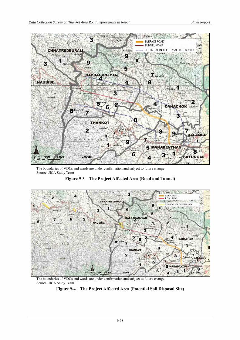
Data Collection Survey on Thankot Area Road Improvement in Nepal Final Report
9-18
The boundaries of VDCs and wards are under confirmation and subject to future change Source: JICA Study Team
Figure 9-3 The Project Affected Area (Road and Tunnel)
The boundaries of VDCs and wards are under confirmation and subject to future change Source: JICA Study Team
Figure 9-4 The Project Affected Area (Potential Soil Disposal Site)

Data Collection Survey on Thankot Area Road Improvement in Nepal Final Report
9-19
9.7.2 Population and Ethnicity/Caste
(1) Population The information of Ward-wise number of population and households in the Project Affected Area was collected from the National Population Census 2011.
There is possibility that the number in the following table does not include population and households who are renting rooms and houses. In the EIA Census Survey, it is necessary to include those tenants as stakeholder of the Project.
Table 9-14 Ward-Wise Number of Population and Households in the Project Affected Area Type of Impacts Population
1) Planned alignment 2)
Existing road
District VDC Ward 1)-1
Surface road
1)-2 Tunnel
road
1)-3 Potential
soil disposal
2)-1 Section
of existing
road to be bypassed
House Hold Total Male Female
Kathmandu Balambu 1 * 287 1,202 604 598 7 * 204 901 441 460 Mahadevsthan 1 X Y 541 2,265 1,133 1,132 5 Y 407 1,595 813 782 7 * Y 775 3,193 1,617 1,576 8 * 238 967 477 490 9 X 87 478 236 242 Dahachok 1 * 88 431 213 218 2 * 274 1,306 631 675 3 X 148 712 343 369 4 X 111 534 279 255 8 * 65 261 140 121 Thankot 2 Y 216 948 492 456 3 Y 197 943 466 477 6 Y 164 735 374 361 7 Y 328 1,356 684 672 8 X Y 1,126 4,615 2,396 2,219 9 Y 137 604 300 304 Baad 1 * 127 580 282 298 Bhanjyang 2 * Y 122 525 268 257 3 X 101 481 241 240 4 X 42 195 99 96 5 X Y 108 479 241 238 6 * Y 50 245 118 127 7 * Y 153 685 337 348 8 * 28 133 65 68 9 X Y 86 456 222 234
Dhading Naubise 3 X 225 955 461 494 4 X 350 1,606 763 843 7 X 512 2,437 1,254 1,183 Chhatre 1 X Y 147 627 301 326 Dyaurali 3 Y 180 771 352 419
Type of Impacts : See Table 9-12. X : 50 m ROW for surface road, and tunnel alignment. Defined as ‘directly affected area.’ * : Within 500 m from the boundary of the ROW. Defined as ‘indirectly affected area.’ Source: National Population Census 2011, Household and Population by Sex, Ward Level, Central Bureau of Statistics,
November 2012

Data Collection Survey on Thankot Area Road Improvement in Nepal Final Report
9-20
(2) Household Size Calculated from ward-wise number of population and households, the average size of one household in the Project Affected Area is 4.36, as shown in Table 9-15.
Table 9-15 Average Household Size in the Project Affected Area District VDC Ward Household Population Average HH Size
Kathmandu 436,344 1,744,240 4.00 Balambu 1 287 1,202 4.19 7 204 901 4.42 Mahadevsthan 1 541 2,265 4.19 5 407 1,595 3.92 7 775 3,193 4.12 8 238 967 4.06 9 87 478 5.49 Dahachok 1 88 431 4.90 2 274 1,306 4.77 3 148 712 4.81 4 111 534 4.81 8 65 261 4.02 Thankot 2 216 948 4.39 3 197 943 4.79 6 164 735 4.48 7 328 1,356 4.13 8 1,126 4,615 4.10 9 137 604 4.41 Baad 1 127 580 4.57 Bhanjyang 2 122 525 4.30 3 101 481 4.76 4 42 195 4.64 5 108 479 4.44 6 50 245 4.90 7 153 685 4.48 8 28 133 4.75 9 86 456 5.30
Dhading 73,851 336,067 4.55 Naubise 3 225 955 4.24 4 350 1,606 4.59 7 512 2,437 4.76 Chhatre 1 147 627 4.27 Dyaurali 3 180 771 4.28
Project Affected Area Total 7,624 33,221 4.36 Source: National Population Census 2011, Household and Population by Sex, Ward Level, Central
Bureau of Statistics, November 2012 District : National Population and Housing Census 2011 (Table 12), Volume 01, Central Bureau
of Statistics, November 2012 VDC : National Population Census 2011, Household and Population by Sex, Ward Level,
Central Bureau of Statistics, November 2012
(3) Ethnicity/Caste The information of Ward-wise number of population and households by Caste/Ethnicity in the Project Area was collected from the VDC Profile documents of each VDC.

Data Collection Survey on Thankot Area Road Improvement in Nepal Final Report
9-21
VDC Profile of Balambu and 2 others in Dhading District were not yet collected.
In the Project Affected Area in 3 VDCs shown in Table 9-16, population who belong to Dalit community consisted of 5.9%. In the Project Affected Area in Baad Bhanjyang shown in Table 9-17, households that belong to Dalit community consisted of 10.6%.
During this Study, DOR/GESU and MOSTE (EIA) confirmed that no significant accumulation of those population is expected in the Project Area.
In the next phase of the Study, 1) interviews to the affected VDC Secretaries, 2) public consultations, 3) census survey of the households within the ROW shall be conducted to clarify the existence and needs of socially and economically vulnerable population to be affected.
Table 9-16 Ward-Wise Number of Population and Households by Caste/Ethnicity
Population by Ethnicity
VDC Ward Brahmin Chhatre Newar Dalit Others
(Including indigenous group and others)
Total
Mahadevsthan 1 118 154 1,031 60 144 1,507
5 139 140 436 100 90 905
8 58 319 44 5 292 718
9 18 139 172 82 191 602 Dahachok 1 79 505 20 3 82 689
2 78 82 19 0 1,125 1,304
3 46 402 14 185 13 660
4 29 460 30 5 0 524
8 86 66 0 0 26 178 Thankot 8 291 403 1,045 100 302 2,141
Total 942 2,670 2,811 540 2,265 9,228 (%) 10.2% 28.9% 30.5% 5.9% 24.5% 100.0%
Source: VDC Profile (Mahadevsthan 2068(2011/12), Dahachok 2069(2012/13), Thankot 2067(2010/11))
Table 9-17 Ward-Wise Number of Households by Caste/Ethnicity
Household Number by Ethnicity
VDC Ward Brahmin Chhatre Newar Dalit Others
(Including indigenous group and others)
Total
Baad Bhanjyang 1 14 53 0 45 0 112
2 53 19 0 1 1 74
3 57 20 2 1 3 83
4 6 19 0 0 16 41
5 15 53 4 6 27 105
6 14 17 1 18 0 50
7 9 74 19 1 13 116
9 0 0 0 0 98 98
Total 168 255 26 72 158 679 (%) 24.7% 37.6% 3.8% 10.6% 23.3% 100.0%
Source: VDC Profile (Baad Bhanjyang 2067(2010/11))


Data Collection Survey on Thankot Area Road Improvement in Nepal Final Report
10-1
Chapter 10 Project Implementation Plan
10.1 Implementation Plan
10.1.1 General
Implementation plan for the construction, operation and maintenance of the optimum route mentioned in Chapter 5 is covered hereunder. This includes the development policy of the road, project prioritization, proposed implementing organization, financial source and implementing schedule.
10.1.2 Development Policy
The policies that apply for the smooth implementation of the project are listed here under;
i) The road will be developed as a bypass of the existing Tribhuvan Highway and will be similarly classified into national highway.
ii) The road will also be designated as a section of Mid-hill Highway and will be enlisted in the National Priority Projects to make it eligible for provision of stable and continuous power supply from Nepal Electricity Authority (NEA).
iii) The project road will be constructed under the soft loan from the government of Japan.
iv) The project will be implemented under the joint venture between a local and Japanese contractor(s) where the Japanese contractor will transfer knowledge and technology to local contractor.
v) Foreign Co-operation Branch, DOR will handle during the design stage of the project. A Project Management Unit will be established in the Bi-lateral Cooperation Unit under Foreign Co-operation Branch, which will handle the construction stage.
vi) Funding for the maintenance of the road and tunnel will be provided by Roads Board Nepal. However, for the operation of the tunnel, funding will be provided by DOR.
vii) A special unit will be established within the Kathmandu Division Office for handling the operation and maintenance of the project road.
viii) Special equipment and material required for construction of tunnel will be procured from Japan. Others will be procured locally or from a third country.
10.1.3 Project Prioritization
The 13th three-year plan (2013/14-2015/16) of Nepal has highlighted the importance of expansion of roadways and development of physical infrastructure for achieving the mid and long term goals and has given high priority for the development of Mid-hill Highway (also a part of Asian Highway)

Data Collection Survey on Thankot Area Road Improvement in Nepal Final Report
10-2
On the other hand, the road project includes a 2.3km long tunnel, which demands continuous supply of power. It has been learnt from Nepal Electricity Authority (NEA), that provision of stable and continuous supply of electricity is possible, if the project (road) is a National Priority Project.
Therefore, for smooth implementation of the project and proper post-construction operation and maintenance, it is necessary that the road project be designated as a national priority project.
10.1.4 Financial Source
The DOR conducted the Feasibility Study of a tunnel road in the study area in 2013 under its own budget. In the Study, the construction of the proposed tunnel is concluded to be feasible. However, the project is not proceeding mainly because the DOR is facing financial difficulty for funding from its local fund and has sought financial help from International Donors including the government of Japan.
Under such circumstances, Japan has shown interest in offering financial assistance and took up the pre-feasibility study of the project. If agreed by the government of Nepal, financial assistance from Japan will be available as a soft loan, given that the project is economically feasible and the construction is implemented under the Joint Undertaking Mutual Partnership (JUMP) scheme of Japan. JUMP is a scheme where the construction work will be carried out under a joint venture between a local construction company and a Japanese construction company.
10.1.5 Application of Japanese Construction Technology The problems of the existing road are as follows:
1) Steep vertical alignment 2) Poor horizontal alignment 3) Slope safety due to geological condition
There is no road improvement measure to solve these three problems at once and the only applicable method is to provide a tunnel. Therefore, the tunnel is planned to avoid the above-mentioned problems for the most critical sections.
The Japanese tunnel technology has been improved mainly to in order to conquer poor geological conditions in Japan. This experience and the technology obtained are both useful in the tunnelling which will be used in road construction in Nepal whose geological condition is complex and mostly weak as ground for tunnel.
The technology in common use in Japan consists of three methods. One is NATM for Mountains, the other is Shield Tunnel for soft flat area and another is Cut and Fill tunnel in shallow tunnels. Shield

Data Collection Survey on Thankot Area Road Improvement in Nepal Final Report
10-3
is very expensive and not applicable in rocks. Cut and Fill is not applicable in steep mountains. Therefore only NATM is applicable to mountainous area. Japan is a mountainous country similar to Nepal and it’s geological and topographical condition is also identical. Under such similarities, application of Japanese technology is deemed to be most desirable from the following points of view.
1) Highly experienced: among technically developed countries, Japan stands on top in terms of experience (excavation volume)
Japan: 15 million cubic meters Germany: 4 million cubic meters Norway: 1.8 million cubic meters
2) Export of Japanese tunnel technology: In recent decade, Japanese contractors had about 7.5billion NRs (25% tunnels abroad) contract.
3) Technical Backups by Industry, Academic and Government Cooperation, by Tunnel Technology Association etc. including technical standards and other publications.
4) Establishment of technical standards such as Tunnel design standards of Road Association and Ministry of Land Infrastructure, Transport and Tourism Technical specification of tunnel by Japan Institute of Civil Engineering, various technical reports by Tunnel Technology Association and so on.
5) Quality control based on the Measurement: the methods and systems of measurement, analysis, evaluation, feedback have been established.
6) Various innovation of tunneling such as:
- Fore-piling and fore-poling - NATM constructed in Urban - Advanced Schedule and Safety Control.
The technology transfer of this tunnel project can be done in both the engineering and the construction stage to the local contractors of Nepal as well as the DOR. The Engineering of the tunnel is the essence of the established technical standards and their back grounds described in 3) and 4) above for the next road tunnel planning, construction and maintenance in Nepal. The construction of tunnelling is mainly the quality control of NATM and Road Section, which is absolutely larger than the conventional hydro-tunnels in Nepal, and is the various advanced tunnelling items as described in 5) and 6) above.
10.1.6 Transfer of Japanese Technology to Nepal
(1) Technical Explanatory Meeting Japanese tunnel technology is the one of the most advanced countries in the world. To transfer the Japanese tunnel technology to local engineers is the very distinguished engineering education. From
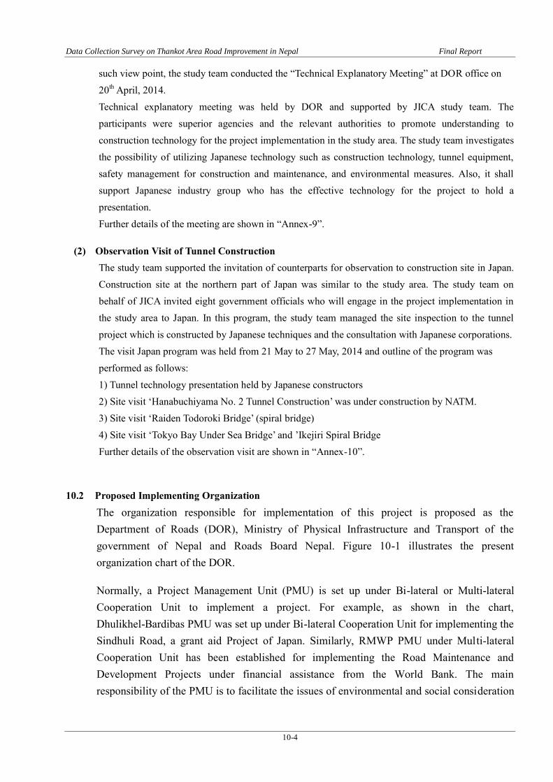
Data Collection Survey on Thankot Area Road Improvement in Nepal Final Report
10-4
such view point, the study team conducted the “Technical Explanatory Meeting” at DOR office on 20th April, 2014. Technical explanatory meeting was held by DOR and supported by JICA study team. The participants were superior agencies and the relevant authorities to promote understanding to construction technology for the project implementation in the study area. The study team investigates the possibility of utilizing Japanese technology such as construction technology, tunnel equipment, safety management for construction and maintenance, and environmental measures. Also, it shall support Japanese industry group who has the effective technology for the project to hold a presentation. Further details of the meeting are shown in “Annex-9”.
(2) Observation Visit of Tunnel Construction The study team supported the invitation of counterparts for observation to construction site in Japan. Construction site at the northern part of Japan was similar to the study area. The study team on behalf of JICA invited eight government officials who will engage in the project implementation in the study area to Japan. In this program, the study team managed the site inspection to the tunnel project which is constructed by Japanese techniques and the consultation with Japanese corporations. The visit Japan program was held from 21 May to 27 May, 2014 and outline of the program was performed as follows: 1) Tunnel technology presentation held by Japanese constructors 2) Site visit ‘Hanabuchiyama No. 2 Tunnel Construction’ was under construction by NATM. 3) Site visit ‘Raiden Todoroki Bridge’ (spiral bridge) 4) Site visit ‘Tokyo Bay Under Sea Bridge’ and ’Ikejiri Spiral Bridge Further details of the observation visit are shown in “Annex-10”.
10.2 Proposed Implementing Organization
The organization responsible for implementation of this project is proposed as the Department of Roads (DOR), Ministry of Physical Infrastructure and Transport of the government of Nepal and Roads Board Nepal. Figure 10-1 illustrates the present organization chart of the DOR.
Normally, a Project Management Unit (PMU) is set up under Bi-lateral or Multi-lateral Cooperation Unit to implement a project. For example, as shown in the chart, Dhulikhel-Bardibas PMU was set up under Bi-lateral Cooperation Unit for implementing the Sindhuli Road, a grant aid Project of Japan. Similarly, RMWP PMU under Multi-lateral Cooperation Unit has been established for implementing the Road Maintenance and Development Projects under financial assistance from the World Bank. The main responsibility of the PMU is to facilitate the issues of environmental and social consideration

Data Collection Survey on Thankot Area Road Improvement in Nepal Final Report
10-5
and coordinate with other concerned organizations.
After construction, generally the maintenance responsibilities of a road are handed over to the concerned division office under Maintenance Branch of the DOR. At present, the maintenance responsibility of the objective section lies under two division offices as shown in Table 10-1.
Table 10-1 Division Offices and Responsibilities
Office Name Responsible Stretch Office Location (District) Remarks
1 Kathmandu Division Office
Kalanki to Naghdhunda (Within Kathmandu District)
Gyaneswor (Kathmandu))
From next year, the division is planned to be divided into two. North and South Kathmandu Division
2 Dhading Division Office
Nagdhunga to Naubise (Gulmi) (Within Dhading District)
Bharatpur (Chitwan)
Source: JICA Study Team
From this perspective, the operation and maintenance of the project road needs to be undertaken by these two division offices. However, instead of demarcating the responsibilities, it is proposed to establish a special unit within the Kathmandu Division under Central Regional Road Directorate and entrust the operation and maintenance work to that specific unit and have it monitored by the Central Regional Road directorate for following reasons;
i) The project road includes a tunnel which is apparently the first of its kind in the road network of Nepal and thus needs a different but extensive attention in its operation and maintenance,
ii) The division office looking after the section inside Dhading District is in Bharatpur, approximately 100km away from the project road, and is therefore physically difficult and impractical for conducting regular inspection of the project road. Kathmandu Division Office is in the perimeter of about 10kms.

Data Collection Survey on Thankot Area Road Improvement in Nepal Final Report
10-6
Source: DOR
Figure 10-1 Organization Chart of Department of Roads
10.3 Organization Chart of Department of Roads
10.3.1 Project Implementation Activities
(1) Feasibility Study
Following this study, a Feasibility Study is recommended to be conducted to;
- prepare preliminary design to determine the project scope for budgetary purposes - finalize the road alignment and tunnel and bridge location for preparation for right-of-way
acquisition, staking of the road reserve limits and conducting cadestral surveys. - prepare the construction plan including procurement plan, construction method and
construction schedule. - conduct environmental impact assessment including project affected persons and
structures. - determine the economic and financial viability of the project
(2) Commencement of the Project
Following estimation of the project cost, which is based on the preliminary design during the feasibility study, preparation of fund is required. DOR will prepare for funds for undertakings covered by the government of Nepal such as fund required for land acquisition, compensation, utility relocation etc.

Data Collection Survey on Thankot Area Road Improvement in Nepal Final Report
10-7
(3) Consultant Selection
DOR will proceed to procure consultant for detailed design and construction supervision during the feasibility study.
(4) Environmental Impact Assessment
Environmental impact assessment report and resettlement plan will be prepared by GESU, DOR and submitted to MOSTE for its approval.
(5) Detailed Design and ROW Acquisition
Once the consultant is selected, the consultant will conduct the detailed design and prepare the design documents, construction drawings, prepare tender documents for bidding including specifications and project cost estimate. This is expected to take about a year. On the other hand, DOR will start preparing for land acquisition and resettlement of project affected persons identified by the feasibility study and detailed design prior to construction of road project.
(6) Bidding Process
After preparation and approval of the bid documents during the detailed design, DOR will call out for tendering. The consultant will assist DOR in short-listing the contractors, tendering and bid evaluation process. The tendering is expected to be divided into the following three components;
- Tunnel Civil Work with/without the Access Road - Electrical Work of the Facilities - Mechanical Work of the Facilities
If the tunnel civil work is excluded of the access road, then the tendering for the access road is required to be done independently.
(7) Construction and Supervision
During construction, the consultant will supervise the contractor’s work to control the quality, cost and schedule for successful completion of the project.
(8) Hand-over
After completion of construction, the road will be handed-over to DOR. The road will then be open to traffic. As aforementioned, the maintenance of the road including operation and maintenance of tunnel will be carried out under the responsibility of Kathmandu Division, maintenance Branch, DOR. The Roads Board Nepal (RBN) will finance the routine and recurrent maintenance work.

Data Collection Survey on Thankot Area Road Improvement in Nepal Final Report
10-8
10.3.2 Work
Major works assumed to be undertaken for tunnel work, electric work, mechanical work and for access road is as described below.
(1) Tunnel Work: tunnel work consists of the following;
- 3 months of Preparation including Mobilization - Approximate 33 months of the excavation in the case of Medium-Hard Rock Ground or in
2 directions by 2 parties in case of Weathered Rock Ground - Followed by 9 months of Concrete Lining - 1 months of the preparation of Pavement - 3 months of Pavement in tunnel
(2) Electrical Work
6 months after tunnel completion of tunnel one (1) year of Electric Work is finished
(3) Mechanical Work
6 months after tunnel completion of tunnel one (1) year of Electric Work is finished
(4) Access Road
During the Tunnel Work, Electrical Work and Mechanical Work, Access Road including 3 bridges are started and finished.
(5) Total Duration of the Project
As shown Table 10-2, the total project schedule is approximately 7 years.
10.3.3 Implementation Schedule
The proposed project implementation schedule is presented in Table 10-2.

Da
ta C
ollectio
n S
urvey o
n T
ha
nko
t Area
Ro
ad
Imp
rovem
ent in
Nep
al
Fin
al R
epo
rt
10-9
Table 10-2 ' Implementation Schedule
▼
Bridges
month
Finish Work
year 2014 2015
Pavement Preparation
Sign
Preparatory Work
Mobilization
Access
Road
2021
Tender-Electric Work
Tender-Mechanical Work
Pavement
Tender-Civil Work
2017 2018 2019
Tunnel Excavation
Tunnel Civil Work
2016
Demobilization
Consulting
Application for Foreign Financial Assistance
Appraisalon the Application
Construction Supervision
Feasibility Study
Detailed Design
Pavement
Earth Work
Electric Work
Mechanical Work
Employment of Consultant
Concrete Lining
2020

Data Collection Survey on Thankot Area Road Improvement in Nepal Final Report
10-10
10.4 Project Framework for Feasibility Study
As a preparation for the next phase study of this project, a framework briefly summarizing the technical requirements, like data and survey needs, design works, required expertise and institutions to be consulted is discussed hereunder.
10.4.1 Technical Requirement
(1) Review of Route Selection
Although the optimum route has been selected within the framework of this project, the review of the route selection needs to be carried out to minimize the project cost, adverse impact on natural environment and number of affected houses (affected persons) and from the perspective of the traffic volume including inter-connectivity between cities/towns.
(2) Traffic Demand Forecast
Future traffic volume shall be estimated based on the results of the traffic survey conducted and by taking the following items into consideration.
i) Land use and development plans of the study area ii) Socio-economic framework iii) Established target year
(3) Study of Basic Design Concept
It is necessary to establish basic concept for the design of the objective road by confirming the function and the designation of the road. In connection to this, collection and study of the prevailing laws, rules and acts including standards relevant to the transport infrastructure are suggested.
10.4.2 Data and Survey Needs
(1) Traffic Count
In order to understand the present traffic condition of the study area and to collect basic data such as the effectiveness indicator for estimation of future traffic demand as well as for the purpose of post evaluation, collection of present available traffic data together with conducting of following supplementary surveys are required.
i) Traffic count (1 weekday and 1 weekend, 24 hours, 2 locations) ii) OD survey (1 weekday and 1 weekend, 12 hours, 2 locations) iii) Travel time (1 weekday and 1 weekend, 2 trips)
(2) Natural Condition Survey
Following natural condition surveys are deemed necessary in order to secure the precision for the outline design of the road and the tunnel.

Data Collection Survey on Thankot Area Road Improvement in Nepal Final Report
10-11
1) Geo-technical Investigation
Collection of topographical map, geological map and other relevant maps and implementation of geo-technical investigations are suggested for design purpose of road, structures (bridges, culverts) and tunnels. Some of the major investigations are as follows;
i) Standard Penetration Test ii) Electric Resistivity Topography iii) Seismic Refraction Topography iv) Laboratory test for physical properties of soil
2) Topography Survey
Topography survey and route survey should be conducted for the purpose of identifying the area of land required for acquisition and for the design work of road, bridges and tunnel portal.
3) Climate and Hydrology Survey
In order to establish the design criteria for the outline design of the road, bridge and tunnel, collection of available documents and data, meetings and discussions with the concerned organizations and site reconnaissance should be conducted.
10.4.3 Preliminary Design, Construction Planning, Land Acquisition and Cost Estimation
The followings should be conducted;
i) Confirm the project financial source and determine the scope of the outline design accordingly,
ii) For bridges and tunnel, several alternatives should be considered followed by a comparative study with respect to construction, maintenance, and economical efficiencies and propose the design concept for the project,
iii) An outline design should be conducted in the following manner; a) Route planning b) Plan, profile and cross section of road c) Pavement design d) Structural design (Bridge and Culverts etc.) e) Tunnel design f) Other structural design (if any) g) Preparation of Quantity spread-sheet h) Unit rate investigation, procurement of material and equipment planning i) Construction planning, Cost estimate j) Implementation schedule
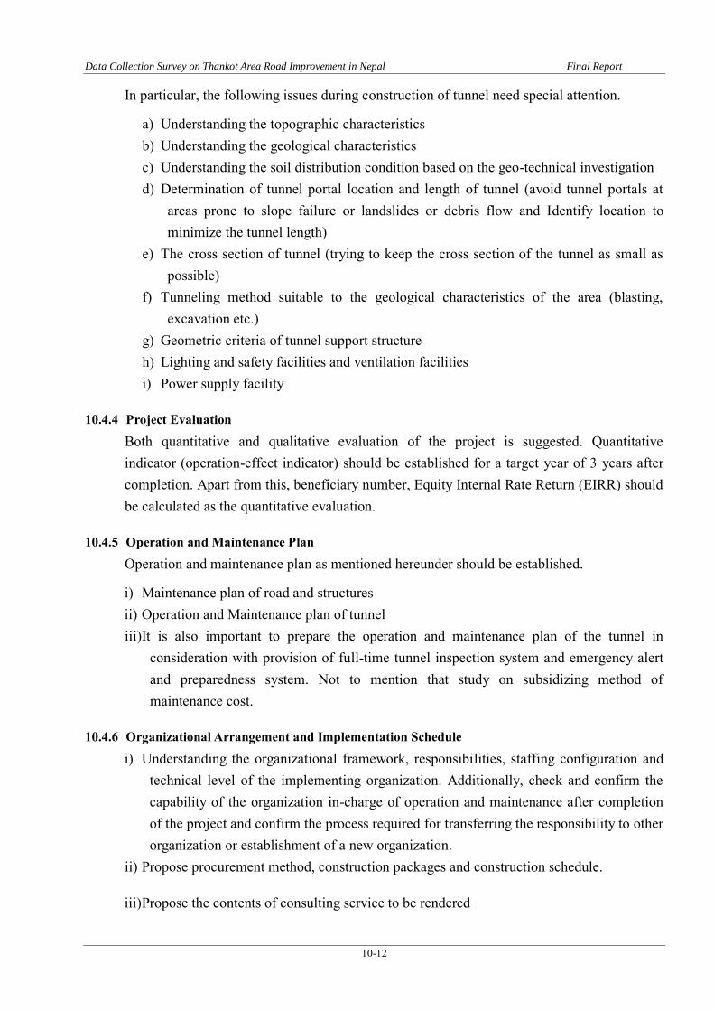
Data Collection Survey on Thankot Area Road Improvement in Nepal Final Report
10-12
In particular, the following issues during construction of tunnel need special attention.
a) Understanding the topographic characteristics b) Understanding the geological characteristics c) Understanding the soil distribution condition based on the geo-technical investigation d) Determination of tunnel portal location and length of tunnel (avoid tunnel portals at
areas prone to slope failure or landslides or debris flow and Identify location to minimize the tunnel length)
e) The cross section of tunnel (trying to keep the cross section of the tunnel as small as possible)
f) Tunneling method suitable to the geological characteristics of the area (blasting, excavation etc.)
g) Geometric criteria of tunnel support structure h) Lighting and safety facilities and ventilation facilities i) Power supply facility
10.4.4 Project Evaluation
Both quantitative and qualitative evaluation of the project is suggested. Quantitative indicator (operation-effect indicator) should be established for a target year of 3 years after completion. Apart from this, beneficiary number, Equity Internal Rate Return (EIRR) should be calculated as the quantitative evaluation.
10.4.5 Operation and Maintenance Plan
Operation and maintenance plan as mentioned hereunder should be established.
i) Maintenance plan of road and structures ii) Operation and Maintenance plan of tunnel iii) It is also important to prepare the operation and maintenance plan of the tunnel in
consideration with provision of full-time tunnel inspection system and emergency alert and preparedness system. Not to mention that study on subsidizing method of maintenance cost.
10.4.6 Organizational Arrangement and Implementation Schedule
i) Understanding the organizational framework, responsibilities, staffing configuration and technical level of the implementing organization. Additionally, check and confirm the capability of the organization in-charge of operation and maintenance after completion of the project and confirm the process required for transferring the responsibility to other organization or establishment of a new organization.
ii) Propose procurement method, construction packages and construction schedule.
iii) Propose the contents of consulting service to be rendered

Data Collection Survey on Thankot Area Road Improvement in Nepal Final Report
10-13
iv) Establish land acquisition schedule, standard schedule for procurement as according to JICA regulation and prepare overall implementation schedule.
10.4.7 Rough Estimation of Project Cost
Estimate roughly the project cost in the following manner;
i) Construction cost ii) Price escalation affecting the construction cost iii) Contingency iv) Consultant fee (including price escalation and contingency) v) Others (land acquisition and compensation fee, taxes, general expenditure for implanting
agency, interests etc. vi) Contract out Fee for operation and maintenance vii) Initial operation cost viii) Cost for levelling the compensated land ix) Expenditure budget for seminar and training x) Other relevant expenses
10.4.8 Required Expertise
For smooth implementation of the next study, involvement of following expertise is recommended.
i) Team Leader (Road Planner) ii) Tunnel Engineer (Planning) iii) Highway Engineer (Design) iv) Tunnel Structural Engineer (Structure design) v) Tunnel Mechanical Engineer (Mechanical design) vi) Bridge Engineer vii) Natural and Social Environmentalist viii) Geologist ix) Engineer (Natural Condition Surveys)
10.5 Organizations to be Consulted
This project, being first of its kind in terms of road tunnel, it is expected that consultations will be necessary with various institutions and organizations. Some of the major relevant institutions and organizations are as listed in Table.

Data Collection Survey on Thankot Area Road Improvement in Nepal Final Report
10-14
Table 10-3 List of Relevant Organizations
Major Relevant Organization Duties and Responsibilities
1 Department of Roads(DOR)
Implementing Agency. Foreign Co-operation Branch (Responsible Branch), Bridge Unit (design, construction and maintenance of
bridge), GESU(review of EIA, RAP, approval of soil disposal are)
2 Ministry of Physical Infrastructure and Transport (MOPIT)
・ Ministry for approval of the Project ・ Approval of alignment determined in the
feasibility study.
・ Inform and coordinate with concerned organization for relocation of affected utilities
3 Ministry of Finance ・ Ministry for approval of the Project ・ Decide acceptance/refusal of loan
4 Compensation Determination Committee ・ Committee to decide and conduct land
acquisition and compensation
5 Ministry of Home Affairs ・ Ministry where claims connected to land
acquisition are filed for hearings and judgment
6 Ministry of Science Technology and Environment
Approval of the EIA
7 Ministry of Forests and Soil Conversation (MOFSE)
Responsible for National forests and reserves
8 DOR
Division Office (KTM) Responsible for construction and maintenance of
roads within Kathmandu District
Division Office (Bharatpur) Responsible for construction and maintenance of
roads within Dhading District
9 Roads Board Nepal Responsible for routine and recurrent maintenance work
10 Nepal Electricity Authority (NEA) Power supply (tunnel)
11 District Development Committee District level matters (Land acquisition, EIA etc)
12 Village Development Committee Village level matter (Land acquisition, EIA ets.)
13 Nepal Tunnel Association (NTA) Standards and specifications for tunnels Source: JICA Study Team

Data Collection Survey on Thankot Area Road Improvement in Nepal Final Report
11-1
Chapter 11 Expected Outcome and Recommendation
11.1 Expected Outcome Economic and trade activities are flourishing in Kathmandu through the network of roads connecting neighboring India and the Kathmandu Valley. However, the Kathmandu Valley itself is located in the basin within surrounding mountains, therefore, the transportation of goods and commodities from India have to inevitably pass through the steep slopes and sharp curves of the Thankot Pass. With the proposal of building a tunnel at Thankot Pass, this project will bear huge economic benefits as it will greatly relieve traffic congestions, reduce the number of accidents and decrease travel time.
Source: JICA Study Team
Figure 11-1 Location of Proposed Tunnel Map
11.1.1 Shortening of Travel Time The most viable and effective factor among several other economic benefits for this project is the shortening of travel time. Due to the steep gradient of more than 10% and numerous sharp curves, every car, bus and truck has to significantly slowdown as they pass through Thankot Pass. As half of the vehicles passing through Thankot Pass are made up of heavy vehicles such as buses and trucks especially those that are ferrying goods and commodities from India, massive slowdowns are encountered by the rest of the other road –users. With the completion of the proposed tunnel, traffic flow will be smoother as well as travel time towards destination will be shortened.
In order to calculate the travel time before and after completion of the proposed tunnel, the study team has performed velocity survey. The result is that travel time could be reduced by about 20 minutes.

Data Collection Survey on Thankot Area Road Improvement in Nepal Final Report
11-2
11.1.2 Shortening of Travel Distance A road with steep slope and a sharp curve is naturally increased in distance. Therefore, the route of the tunnel of this proposed project is planned to be located directly below the steepest slope and curve at Thankot Pass. Thus the extended distance of the road will be shortened with the merging of the tunnel with a straight line distance. However, this project is formed with both tunnel and approach road. There are tunnel with a length of 2.35 km and approach road with a length of 2.25 km, a total length of 4.60 km.
Without the tunnel and approach road, the distance of the existing road is 7.60 km. Therefore, with the construction of a tunnel, the travel distance will be shortened by 3.0 km.
11.1.3 Saving of Vehicle Running Cost As mentioned above, after completion of the proposed tunnel, it is possible to reduce travel time by about 20 minutes and to have travel distance shortened by about 3.0 km. This will result in less fuel consumption as well as longer engine life–span. Thus, this will contribute to both energy and cost-savings.
11.1.4 Reduction of Traffic Accidents Due to the numerous steep slopes and sharp curves at Thankot Pass, the possibilities of road accidents are undeniable. Collisions between oncoming vehicles, vehicles falling off cliffs while avoiding oncoming vehicles and the sudden breakdowns of older vehicles that cause huge traffic congestions are some of the happenings at Thankot Pass. However, with the completion of the proposed tunnel, traffic accidents can be greatly reduced.
11.1.5 Application as a Model Case Nepal is a landlocked country with around 60% of the country covered by mountains. Therefore, there are many places similar to Thankot Pass where steep slopes and sharp curves dominate the road system. However, with the introduction of tunnels these sharp curve and steep slope in the road system can be greatly countered. But due to huge construction costs, the requirement of special construction materials and equipment as well as special construction technology, a tunnel has never been built before in Nepal.
Therefore, it is favorable to introduce the first tunnel construction at Thankot Pass as it will serve as a model case for the future development of tunnel projects in Nepal.
11.1.6 Conclusion As mentioned above, this tunnel project connecting Kathmandu and India through the Tribhuvan Highway will bring great economic prospects into Nepal. It is strongly believed that with the implementation of this project, the infrastructure development of the country will improve steadily whereby drawing strong foreign investments into the country. Although this

Data Collection Survey on Thankot Area Road Improvement in Nepal Final Report
11-3
proposed tunnel project in Thankot Pass will be the first model case in Nepal, it will be a ’successful’ model case as there are many places in Nepal where tunnel constructions can be implemented in the future.
As mentioned above, there are so many advantages for the country of Nepal to implement the tunnel construction at Thankot. They are not only district development and economics, but also technical transfer to Nepalese engineers of DOR or other related institutions. The tunnel construction starts from a planning, design, construction and inauguration. These processes contain a various modern civil engineering technologies.
It is a revolutionary project that a tunnel technology is introduced into Nepalese engineers, moreover, the technology transfer by this project will be enhanced the country of Nepal to develop more in the future.
11.2 Recommendation of the Project
11.2.1 Promotion of Proper District Development Over the years, rapid urbanization of the Kathmandu Valley is taking place. By 1991, most of the inner sector of the Ring Road has become built-up areas and almost a decade later, around 2000 the expansion of urban areas has advanced to the feeder roads, extending radially and externally of the Ring Road. Presently, more than a decade later urbanization has sprawled to the suburbs without proper town planning or road networks. Due to lack of amendments in land use planning and archaic enforcements of land development regulations, Thankot area has witnessed especially rapid unregulated housing developments in area near the proposed tunnel portal. Therefore, using this proposed project as a turning point to propel proper and careful land use planning as well as proper housing development and proper road construction projects for the good prospects of the immediate future.
11.2.2 Inducement of Other Projects Due to the close proximity with Kathmandu, Thankot could be a choice future business development region whereby the construction of commercial and residential buildings, logistic facility terminals, educational centers as well as other related concerns for the promotional of both home and foreign investments. Therefore, it is a necessity to prepare proper laws and regulations for land use legislation, for town planning development and road network planning.
The urban transport master plan (M/P) for Kathmandu Valley will be conducted by JICA soon. The preparation of the M/P includes Thankot area, so that both M/P and this tunnel projects should be harmonized with each other.

Data Collection Survey on Thankot Area Road Improvement in Nepal Final Report
11-4
11.2.3 Preservation of the Existing Road It is believed that traffic volume of the existing road will be greatly reduced after completion of the proposed tunnel. Nevertheless, the preservation and maintenance of the existing road should be pursued as inhabitants of the area especially those involving in farming activities as well as other businesses should not suffer nor should they be negatively affected by the tunnel project.
Moreover, if the maintenance of the existing road should be neglected, the deterioration of the pavement, depression of the road shoulder and induction of slope failures could cause serious problems including traffic accidents.

ANNEXES
ANNEX-1 Cost Benefit Flow for 2 Previous Projects
ANNEX-2 Traffic Count Data
ANNEX-3 Boring Data (FBC Report)
ANNEX-4 EPA Amendment (Gazette- Section 58, No. 44, Part 5)
ANNEX-5 EPR AMMENDMENT Schedule -2 (Relating to EPR SECTION 3)
ANNEX-6 Table of Contents of MOFSC Project Approval Request
ANNEX-7 Sample Table of Contents of EIA Scoping Document
ANNEX-8 Sample of Table of Contents of EIA Terms of Reference Document
ANNEX-9 Technical Explanatory Meeting
ANNEX-10 Observation Visit Tunnel Construction
ANNEX-11 Study Team Member List

A-1
ANNEX-1 Cost Benefit Flow for 2 Previous Projects
1. Feasibility Study on the Construction of Kathmandu-Naubise Road (2001 JICA)

A
-2
2.
Feasibility Study on Tunnel Roads (2013 D
OR
)

A-3
ANNEX-2 Traffic Count Data
1. Traffic Count Data Naubise to Kathmandu (Friday, 7th Feb, 2014)
Traffic Count Form (24 Hours) Traffic Count Form (24 Hours)
Road Number or Name: Tribhuvan Highway
Location: Nagdhunga Direction of Traffic: Naubise to KTM Day: Friday
Surveyor Name: Date: 07 February, 2014
Motorised Non-Motorised
3 or more
axles2 axles Max 35 Seats Max 14 Seats
all 3-
w heelers
With or WO
Trailer
Time 1 2 3 4 5 6 7 8 9 10 11 12 13 14 15 16
6:00 - 6:30 0 2 2 5 0 0 1 0 0 0 0 2 0 0 0 126:30 - 7:00 10 9 3 41 3 0 4 2 0 0 0 2 0 0 0 747:00 - 7:30 50 37 1 50 1 0 6 0 0 0 0 4 0 0 0 1497:30 - 8:00 34 33 16 20 2 1 18 1 0 0 0 5 0 0 0 1308:00 - 8:30 23 28 8 9 1 4 6 1 0 0 0 6 0 0 0 868:30 - 9:00 13 24 7 7 3 7 9 0 0 0 0 21 0 0 0 919:00 - 9:30 32 22 1 9 6 3 9 0 0 0 0 27 0 0 0 109
9:30 - 10:00 13 19 3 5 6 6 16 5 0 0 0 21 0 0 0 9410:00 - 10:30 32 40 7 4 6 6 29 0 0 0 0 42 0 0 0 16610:30 - 11:00 23 31 9 4 2 6 18 0 0 0 0 36 0 0 0 12911:00 - 11:30 13 23 5 3 6 2 13 2 0 0 1 18 0 0 0 8611:30 - 12:00 18 26 1 3 5 6 17 2 0 0 0 29 0 0 0 10712:00 - 12:30 14 32 2 4 7 5 18 2 0 0 0 31 0 0 0 11512:30 - 13:00 10 23 5 4 3 7 16 2 0 0 0 24 0 0 0 9413:00 - 13:30 13 16 3 3 3 3 13 4 0 0 0 36 0 0 0 9413:30 -14:00 9 28 9 15 9 3 30 6 0 0 2 36 0 0 0 14714:00 - 14:30 8 19 5 13 9 9 28 4 0 0 0 29 0 0 0 12414:30 - 15:00 15 12 4 13 18 9 32 8 0 0 0 32 0 0 0 14315:00 -15:30 4 12 4 6 13 18 32 6 0 0 0 47 0 0 0 14215:30 -16:00 11 11 4 9 30 13 51 5 0 0 0 46 0 0 0 18016:00 - 16:30 8 16 4 8 15 30 35 4 0 0 0 35 0 0 0 15516:30 - 17:00 5 20 3 15 13 15 37 5 0 0 0 49 0 0 0 16217:00 - 17:30 1 13 7 4 13 26 24 3 0 0 0 65 0 0 0 15617:30 - 18:00 1 15 1 7 8 11 36 3 0 0 0 38 0 0 0 120
360 511 114 261 182 190 498 65 0 0 3 681 0 0 0 2865
18:00 - 18:30 4 29 2 8 13 19 43 8 0 0 0 48 0 0 0 17418:30 - 19:00 9 18 5 7 2 17 25 10 0 0 0 27 0 0 0 12019:00 - 19:30 10 20 5 5 4 10 22 9 0 0 0 14 0 0 0 9919:30 - 20:00 11 18 5 11 2 30 34 4 0 0 0 18 0 0 0 13320:00 - 20:30 12 17 4 3 0 3 17 4 0 0 0 8 0 0 0 6820:30 - 21:00 13 19 2 2 0 12 16 1 0 0 0 10 0 0 0 7521:00 - 21:30 8 15 2 5 2 7 21 3 0 0 0 2 0 0 0 6521:30 -22:00 6 8 0 2 0 3 7 5 0 0 0 3 0 0 0 3422:00 -22:30 4 15 0 1 0 1 8 1 0 0 0 3 0 0 0 3322:30 - 23:00 4 9 2 0 0 2 9 6 0 0 0 2 0 0 0 3423:00 - 23:30 6 9 1 3 0 0 4 5 0 0 0 5 0 0 0 3323:30 - 24:00 3 10 3 0 0 0 9 0 0 0 0 0 0 0 0 2500:00 - 00:30 5 6 0 1 0 0 3 2 0 0 0 1 0 0 0 1800:30 - 01:00 8 11 4 0 0 2 4 4 0 0 0 0 0 0 0 3301:00 - 01:30 19 9 8 0 0 1 5 5 0 0 0 4 0 0 0 5101:30 - 02:00 11 19 5 0 0 1 2 3 0 0 0 1 0 0 0 4202:00 - 02:30 9 10 4 2 0 0 8 12 0 0 0 0 0 0 0 4502:30 - 03:00 14 15 4 3 1 1 5 5 0 0 0 0 0 0 0 4803:00 - 03:30 3 18 4 9 14 0 2 5 0 0 0 1 0 0 0 5603:30 - 04:00 7 11 2 30 0 1 2 5 0 0 0 1 0 0 0 5904:00 - 04:30 13 15 2 52 0 1 1 3 0 0 0 0 0 0 0 8704:30 - 05:00 15 16 1 70 0 1 2 3 0 0 0 1 0 0 0 10905:00 - 05:30 11 16 0 55 0 0 2 1 0 0 0 2 0 0 0 8705:30 -06:00 14 10 1 24 0 0 2 2 0 0 0 2 0 0 0 55
219 343 66 293 38 112 253 106 0 0 0 153 0 0 0 1583
Total 939 1365 294 815 402 492 1249 236 0 0 6 1515 0 0 0 7313
Power
TillerMotor cycle Animal Cart Rick shaw Bicycle
TypeTotal
Motorized
(1 to 9)
Heavy Truck
(>3 axle)
Heavy
TruckMini Truck Large Bus Mini Bus Micro Bus
Car Jeep
Taxi/Van
Utility /
Pickup
Auto
rickshawTractor

A-4
2. Traffic Count Data Naubise to Kathmandu (Saturday, 8th Feb, 2014) Traffic Count Form (24 Hours)
Road Number or Name: Tribhuvan Highway
Location: Nagdhunga Direction of Traffic: Naubise to KTM Day: Saturday
Surveyor Name: Date: 08 February, 2014
Motorised Non-Motorised
3 or more
axles2 axles Max 35 Seats Max 14 Seats
all 3-
w heelers
With or WO
Trailer
Time 1 2 3 4 5 6 7 8 9 10 11 12 13 14 15 16
6:00 - 6:30 15 21 3 33 5 1 1 1 0 0 0 3 0 0 0 836:30 - 7:00 14 15 8 14 3 1 3 0 0 0 0 4 0 0 0 627:00 - 7:30 14 16 4 18 1 0 0 1 0 0 0 4 0 0 0 587:30 - 8:00 11 20 1 16 2 1 3 1 0 0 0 7 0 0 0 628:00 - 8:30 15 26 3 17 6 3 3 10 0 0 0 19 0 0 0 1028:30 - 9:00 11 17 4 4 6 5 3 0 0 0 0 9 0 0 0 599:00 - 9:30 5 32 6 2 3 9 7 3 0 0 0 14 0 0 0 81
9:30 - 10:00 11 28 9 2 8 12 11 4 0 0 0 12 0 0 0 9710:00 - 10:30 13 26 7 3 7 7 7 1 0 0 0 16 0 0 0 8710:30 - 11:00 10 20 0 2 3 10 11 2 0 0 0 25 0 0 0 8311:00 - 11:30 7 26 7 1 9 12 18 6 0 0 0 38 0 0 0 12411:30 - 12:00 8 14 2 4 5 9 17 4 0 0 0 28 0 0 0 9112:00 - 12:30 10 12 2 1 2 7 12 1 0 0 0 21 0 0 0 6812:30 - 13:00 6 14 3 2 5 13 22 3 0 0 0 24 0 0 0 9213:00 - 13:30 2 22 5 3 8 14 25 4 0 0 0 28 0 0 0 11113:30 -14:00 1 12 3 9 8 14 25 4 0 0 0 33 0 0 0 10914:00 - 14:30 2 17 1 6 10 15 39 9 0 0 0 39 0 0 0 13814:30 - 15:00 5 21 3 13 11 18 51 5 0 0 0 39 0 0 0 16615:00 -15:30 5 17 2 6 17 20 40 2 0 0 0 50 0 0 0 15915:30 -16:00 5 17 5 4 11 22 42 3 0 0 0 85 0 0 0 19416:00 - 16:30 12 23 1 5 18 29 56 3 0 0 0 70 0 0 0 21716:30 - 17:00 6 16 2 7 14 22 35 3 0 0 0 65 0 0 0 17017:00 - 17:30 5 9 0 2 4 3 13 1 0 0 0 65 0 0 0 10217:30 - 18:00 14 31 4 5 17 23 63 7 0 0 0 67 0 0 0 231
207 472 85 179 183 270 507 78 0 0 0 765 0 0 0 2746
18:00 - 18:30 19 39 5 32 2 31 65 13 0 0 0 76 0 0 0 28218:30 - 19:00 10 14 3 13 3 12 29 8 0 0 0 50 0 0 0 14219:00 - 19:30 21 12 2 15 3 7 30 6 0 0 0 30 0 0 0 12619:30 - 20:00 21 19 3 10 2 17 39 13 0 0 0 40 0 0 0 16420:00 - 20:30 11 20 0 11 0 14 55 8 0 0 0 24 0 0 0 14320:30 - 21:00 11 11 2 6 0 6 36 3 0 0 0 18 0 0 0 9321:00 - 21:30 26 14 2 9 0 14 28 4 0 0 0 10 0 0 0 10721:30 -22:00 10 8 1 3 0 8 15 4 0 0 0 12 0 0 0 6122:00 -22:30 17 24 0 4 3 12 24 8 0 0 0 14 0 0 0 10622:30 - 23:00 3 9 1 2 1 0 14 3 0 0 0 3 0 0 0 3623:00 - 23:30 6 4 2 2 0 2 12 2 0 0 0 1 0 0 0 3123:30 - 24:00 17 16 2 3 2 1 13 3 0 0 0 4 0 0 0 6100:00 - 00:30 12 3 0 3 0 2 6 4 0 0 0 2 0 0 0 3200:30 - 01:00 17 0 3 0 0 2 8 2 0 0 0 1 0 0 0 3301:00 - 01:30 24 1 2 1 0 0 3 6 0 0 0 0 0 0 0 3701:30 - 02:00 13 13 4 0 0 0 0 10 0 0 0 2 0 0 0 4202:00 - 02:30 17 12 4 5 1 1 4 5 0 0 0 3 0 0 0 5202:30 - 03:00 18 18 4 3 0 0 7 17 0 0 0 2 0 0 0 6903:00 - 03:30 15 10 2 12 0 3 5 7 0 0 0 3 0 0 0 5703:30 - 04:00 34 19 11 49 1 1 7 6 0 0 0 0 0 0 0 12804:00 - 04:30 22 13 0 60 0 0 3 4 0 0 0 2 0 0 0 10404:30 - 05:00 11 7 2 30 2 6 2 0 0 0 0 13 0 0 0 7305:00 - 05:30 23 19 3 43 3 11 14 5 0 0 0 18 0 0 0 13905:30 -06:00 26 44 5 82 2 17 28 13 0 0 0 47 0 0 0 264
404 349 63 398 25 167 447 154 0 0 0 375 0 0 0 2382
Total 818 1293 233 756 391 707 1461 310 0 0 0 1905 0 0 0 10256
Micro BusCar Jeep
Taxi/VanRick shaw Bicycle
Utility /
Pickup
Auto
rickshawTractor
Power
TillerMotor cycle Animal Cart
Heavy Truck
(>3 axle)
Heavy
TruckMini Truck Large Bus Mini Bus
TypeTotal
Motorized
(1 to 9)

A-5
3. Traffic Count Data Kathmandu to Naubise (Friday, 7th Feb, 2014) Traffic Count Form (24 Hours) Traffic Count Form (24 Hours)
Road Number or Name: Tribhuvan Highway
Location: Nagdhunga Direction of Traffic: Kathamndu to Naubise Day: Friday
Surveyor Name: Date: 07 February, 2014
Motorised Non-Motorised
3 or more
axles2 axles Max 35 Seats Max 14 Seats
all 3-
w heelers
With or WO
Trailer
Time 1 2 3 4 5 6 7 8 9 10 11 12 13 14 15 16
6:00 - 6:30 2 9 2 7 4 6 17 3 0 0 0 7 0 0 0 576:30 - 7:00 2 10 0 9 11 21 30 3 0 0 0 15 0 0 0 1017:00 - 7:30 5 9 2 5 4 21 31 5 0 0 0 20 0 0 0 1027:30 - 8:00 5 12 1 20 13 26 37 16 0 0 0 27 0 0 0 1578:00 - 8:30 4 28 1 32 10 33 40 13 0 0 0 34 0 0 0 1958:30 - 9:00 7 14 13 19 16 31 39 6 0 0 0 29 0 0 0 1749:00 - 9:30 3 8 14 12 13 23 31 6 0 0 0 33 0 0 0 143
9:30 - 10:00 5 19 4 6 14 17 25 8 0 0 0 44 0 0 0 14210:00 - 10:30 4 10 5 4 12 13 20 8 0 0 0 35 0 0 0 11110:30 - 11:00 14 14 2 3 13 19 25 9 0 0 0 39 0 0 0 13811:00 - 11:30 11 18 4 2 11 15 35 3 0 0 0 34 0 0 0 13311:30 - 12:00 24 38 6 0 11 19 29 5 0 0 0 47 0 0 0 17912:00 - 12:30 33 15 7 3 12 21 27 4 0 0 0 39 0 0 0 16112:30 - 13:00 24 30 5 1 12 23 27 3 0 0 0 60 0 0 0 18513:00 - 13:30 16 22 2 2 11 17 34 3 0 0 0 53 0 0 0 16013:30 -14:00 30 27 4 5 10 22 24 9 0 0 0 50 0 0 0 18114:00 - 14:30 21 37 3 5 4 22 47 6 0 0 0 39 0 0 0 18414:30 - 15:00 34 39 3 3 12 16 39 8 0 0 0 49 0 0 0 20315:00 -15:30 30 27 1 3 8 11 29 3 0 0 0 49 0 0 0 16115:30 -16:00 28 31 5 10 8 16 28 4 0 0 0 47 0 0 0 17716:00 - 16:30 25 27 4 18 5 12 27 4 0 0 0 51 0 0 0 17316:30 - 17:00 29 24 4 30 2 12 18 4 0 0 0 44 0 0 0 16717:00 - 17:30 23 16 3 22 4 7 25 8 0 0 0 55 0 0 0 16317:30 - 18:00 30 27 4 44 5 7 23 1 0 0 0 44 0 0 0 185
409 511 99 265 225 430 707 142 0 0 0 944 0 0 0 3732
18:00 - 18:30 12 13 5 23 6 2 19 1 0 0 0 17 0 0 0 9818:30 - 19:00 25 25 11 40 0 3 25 1 0 0 0 33 0 0 0 16319:00 - 19:30 18 21 4 36 0 2 19 2 0 0 0 18 0 0 0 12019:30 - 20:00 29 34 2 51 0 1 10 2 0 0 0 18 0 0 0 14720:00 - 20:30 34 28 1 47 2 0 14 5 0 0 0 20 0 0 0 15120:30 - 21:00 38 31 3 40 0 0 11 5 0 0 0 2 0 0 0 13021:00 - 21:30 17 38 0 13 0 1 5 0 0 0 0 1 0 0 0 7521:30 -22:00 30 24 0 10 0 0 8 2 0 0 0 1 0 0 0 7522:00 -22:30 13 17 1 3 0 0 6 0 0 0 0 3 0 0 0 4322:30 - 23:00 9 18 5 1 0 0 1 0 0 0 0 1 0 0 0 3523:00 - 23:30 10 7 0 0 0 0 1 0 0 0 0 0 0 0 0 1823:30 - 24:00 2 11 1 1 0 0 3 1 0 0 0 0 0 0 0 1900:00 - 00:30 3 4 1 0 0 0 2 0 0 0 0 0 0 0 0 1000:30 - 01:00 2 0 0 0 0 0 1 0 0 0 0 0 0 0 0 301:00 - 01:30 0 1 0 0 0 1 2 1 0 0 0 0 0 0 0 501:30 - 02:00 1 8 1 1 0 0 0 1 0 0 0 0 0 0 0 1202:00 - 02:30 0 4 0 1 0 0 0 0 0 0 0 0 0 0 0 502:30 - 03:00 0 0 0 0 0 0 1 2 0 0 0 0 0 0 0 303:00 - 03:30 3 2 0 0 0 0 1 0 0 0 0 0 0 0 0 603:30 - 04:00 0 6 0 0 0 0 6 3 0 0 0 4 0 0 0 1904:00 - 04:30 6 14 1 1 1 1 16 5 0 0 0 2 0 0 0 4704:30 - 05:00 0 11 0 0 1 3 22 0 0 0 0 4 0 0 0 4105:00 - 05:30 4 18 0 1 1 0 20 2 0 0 0 16 0 0 0 6205:30 -06:00 1 22 3 10 2 6 26 1 0 0 0 14 0 0 0 85
257 357 39 279 13 20 219 34 0 0 0 154 0 0 0 1372
Total 1075 1379 237 809 463 880 1633 318 0 0 0 2042 0 0 0 8836
Power
TillerMotor cycle Animal Cart Rick shaw Bicycle
TypeTotal
Motorized
(1 to 9)
Heavy Truck
(>3 axle)
Heavy
TruckMini Truck Large Bus Mini Bus Micro Bus
Car Jeep
Taxi/Van
Utility /
Pickup
Auto
rickshawTractor

A-6
4. Traffic Count Data Kathmandu to Naubise (Saturday, 8th Feb, 2014)
Traffic Count Form (24 Hours)
Road Number or Name: Tribhuvan Highway
Location: Nagdhunga Direction of Traffic: Kathamndu to Naubise Day: Saturday
Surveyor Name: Date: 08 February, 2014
Motorised Non-Motorised
3 or more
axles2 axles Max 35 Seats Max 14 Seats
all 3-
w heelers
With or WO
Trailer
Time 1 2 3 4 5 6 7 8 9 10 11 12 13 14 15 16
6:00 - 6:30 4 21 8 11 7 11 36 9 0 0 0 31 0 0 0 1386:30 - 7:00 5 23 12 5 10 13 44 8 0 0 0 40 0 0 0 1607:00 - 7:30 0 14 8 8 16 29 39 10 0 0 0 41 0 0 0 1657:30 - 8:00 3 16 9 18 20 32 60 16 0 0 0 34 0 0 0 2088:00 - 8:30 5 19 4 23 18 31 53 13 0 0 0 59 0 0 0 2258:30 - 9:00 2 19 5 4 24 21 55 9 0 0 0 54 0 0 0 1939:00 - 9:30 0 16 1 7 13 27 42 5 0 0 0 50 0 0 0 161
9:30 - 10:00 4 18 3 8 10 19 48 11 0 0 0 61 0 0 0 18210:00 - 10:30 2 23 2 2 18 18 37 8 0 0 0 54 0 0 0 16410:30 - 11:00 17 15 4 0 7 14 27 6 0 0 0 53 0 0 0 14311:00 - 11:30 12 29 7 2 11 21 27 7 0 0 0 51 0 0 0 16711:30 - 12:00 12 33 7 1 7 18 22 10 0 0 0 48 0 0 0 15812:00 - 12:30 21 28 10 1 6 19 40 8 0 0 0 50 0 0 0 18312:30 - 13:00 9 32 7 2 12 17 47 3 0 0 0 46 0 0 0 17513:00 - 13:30 10 25 3 2 9 14 18 8 0 0 0 58 0 0 0 14713:30 -14:00 15 22 5 3 3 15 17 6 0 0 0 55 0 0 0 14114:00 - 14:30 18 19 4 2 13 8 21 7 0 0 0 42 0 0 0 13414:30 - 15:00 22 17 4 4 2 11 24 4 0 0 0 41 0 0 0 12915:00 -15:30 16 19 2 6 7 8 26 8 0 0 0 27 0 0 0 11915:30 -16:00 12 16 2 4 5 5 11 4 0 0 0 31 0 0 0 9016:00 - 16:30 12 21 1 21 1 6 15 6 0 0 0 22 0 0 0 10516:30 - 17:00 14 18 2 33 6 8 12 3 0 0 0 26 0 0 0 12217:00 - 17:30 15 21 2 36 6 8 16 3 0 0 0 29 0 0 0 13617:30 - 18:00 13 17 1 17 3 3 12 3 0 0 0 12 0 0 0 81
243 501 113 220 234 376 749 175 0 0 0 1015 0 0 0 3626
18:00 - 18:30 9 11 1 24 5 3 7 3 0 0 0 13 0 0 0 7618:30 - 19:00 6 12 0 32 3 1 8 2 0 0 0 13 0 0 0 7719:00 - 19:30 5 17 1 41 3 0 6 1 0 0 0 4 0 0 0 7819:30 - 20:00 18 19 5 46 2 0 11 5 0 0 0 11 0 0 0 11720:00 - 20:30 7 20 1 22 0 3 2 2 0 0 0 2 0 0 0 5920:30 - 21:00 6 24 1 25 0 0 4 0 0 0 0 1 0 0 0 6121:00 - 21:30 6 15 0 7 0 0 2 2 0 0 0 1 0 0 0 3321:30 -22:00 5 8 0 2 0 1 4 1 0 0 0 0 0 0 0 2122:00 -22:30 7 6 0 1 0 0 1 0 0 0 0 1 0 0 0 1622:30 - 23:00 3 2 0 1 0 1 1 1 0 0 0 1 0 0 0 1023:00 - 23:30 4 3 0 2 0 0 0 2 0 0 0 3 0 0 0 1423:30 - 24:00 12 7 0 3 0 3 7 4 0 0 0 7 0 0 0 4300:00 - 00:30 3 1 1 0 0 0 0 0 0 0 0 0 0 0 0 500:30 - 01:00 0 3 0 0 0 0 2 1 0 0 0 0 0 0 0 601:00 - 01:30 2 0 1 0 0 0 2 2 0 0 0 0 0 0 0 701:30 - 02:00 0 1 0 1 0 0 0 0 0 0 0 1 0 0 0 302:00 - 02:30 4 6 0 1 0 0 4 0 0 0 0 0 0 0 0 1502:30 - 03:00 0 2 0 0 0 0 1 0 0 0 0 0 0 0 0 303:00 - 03:30 3 3 0 0 0 0 0 3 0 0 0 0 0 0 0 903:30 - 04:00 2 7 1 0 1 0 1 2 0 0 0 3 0 0 0 1704:00 - 04:30 0 7 0 0 1 0 5 1 0 0 0 1 0 0 0 1504:30 - 05:00 0 7 0 0 2 0 9 4 0 0 0 4 0 0 0 2605:00 - 05:30 10 10 2 25 2 1 4 5 0 0 0 3 0 0 0 6205:30 -06:00 26 28 4 12 4 13 16 0 0 0 0 13 0 0 0 116
138 219 18 245 23 26 97 41 0 0 0 82 0 0 0 889
Total 624 1221 244 685 491 778 1595 391 0 0 0 2112 0 0 0 9030
Micro BusCar Jeep
Taxi/VanRick shaw Bicycle
Utility /
Pickup
Auto
rickshawTractor
Power
TillerMotor cycle Animal Cart
Heavy Truck
(>3 axle)
Heavy
TruckMini Truck Large Bus Mini Bus
TypeTotal
Motorized
(1 to 9)

A-7
ANNEX-3 Boring Data (FBC Report)

A
-8
Figure A2-1 L
ocation Map of D
rill Hole Sites in T
hankot Area

A-9
1. Boring Log at TA1
BORING LOGPROJECT : DATA COLLECTION SURVEY ON THANKOT AREA
ROAD IMPROVEMENT IN NEPAL
SHEET NO : 1 of 1
9.5
11.5
CHIEFENGINEER F.NAKAJIMA Boring log
prepared by
BORING NO. TA-1 PLACE Imakhel, Thankot NORTH LATITUDE 3,065,274
DATE 21.02.2014 to 03.03.2014 EAST LATITUDE 324,292
A. KOIRALA CHIEF OPERATOR G. Giri
GROUND ELEVATION 1403 (Handy GPS)
BORING DEPTH Boring Machine XUL - 200 Pump
COMPANY NAME JICA (Japan International Cooperation Agency)
Final GWL 0.00 m
Koken
4
9
20
48
68
25
14
13
49
50/13
50/10
15
25
41
100
65
48
51
52
TA-1
49
50
52
46
45
48
DA
TE
DEP
TH
(m
)
BO
RIN
G L
OG
ELEV
AT
ION
PHOTO OF CORE
TY
PE O
F R
OC
K O
R
SOIL
CO
RE
HA
RD
NES
SC
OLO
UR
JOIN
T C
ON
DIT
ION
N V
alue
AN
GLE
Down Vertical
SLO
PE
RO
CK
CL
ASS
IFIC
ATI
ON
JOIN
T S
PAC
E
1
2
DA
TE D E S C R I P T I O N
1
4
2
3
5
6
7
8
9
10
11
12
13
14
15
16
17
18
19
20
21
22
23
24
25
26
27
28
29
30
1
2
3
N Value graph
Down Vertical Flat25.0m
(Alternative A at Kathmandu side)
Sampling
Sampling
yello
wish
grey
Cultivated soil. Fill containing pieces of bricks in grey and brown sandy clayey silt
Alluvisal clay. clayey silt together with gravel size pieces of metasandstone.
Colluvial Soil. Grey gravel size pieces of metasandstone and sand collected from sludge
Lacustrine soil. Dark grey, grey and black clayey sandy silt with gravel size pieces of metasandstone impregnated in sandy silt .
Colluvial Soil .Grey gravel size pieces of mainly metasandstone and some quartz together with silt and sand
sandy silt and carbonaceous stiff clay.
Lacustrine Soil. sandy clayey silt together with gravel size fragments of metasandstone. Sometimes only sand could be collected from sludge.
End of hole
Fill
Grav
elcl
ay
Grav
elG
rave
l
DIR
EC
TIO
N
-
Dar
k gr
eyan
d Gr
ey
Blac
kGr
ey
Grey
and g
reen
ish to
brow
nish
grey
Grey
clay
clay
Gr
avel
-
-
-
-
-
-
-
--
-
-
-
-
-
-
-
-
Ⅳ
Ⅳ
Ⅳ
Ⅳ
Ⅳ
Ⅳ
Ⅳ
Ⅳ
C
C
C
C
-
-
-
-
- -
clay
Frequent impregnation of grey gravels and cobbles of metasandstone observed.
brow
nbr
own

A-10
2. Boring Log at TB1
BORING LOGPROJECT : DATA COLLECTION SURVEY ON THANKOT AREA
ROAD IMPROVEMENT IN NEPAL
SHEET NO : 1 of 1 g
rey
to b
row
nish
gre
y
9.5
11.5
CHIEFENGINEER F.NAKAJIMA Boring log
prepared by
BORING NO. TB-1 PLACE Bad Bhanjang NORTH LATITUDE 3,065,693
DATE 28.02.2014 to 05.03.2014 EAST LATITUDE 323,789
A. KOIRALA CHIEF OPERATOR P. Shrestha
GROUND ELEVATION 1410 (Handy GPS)
BORING DEPTH Boring Machine XUL - 100 Pump
COMPANY NAME JICA (Japan International Cooperation Agency)
Final GWL 0.00 m
Koken
3
5
4
20
50/13
50/11
50/8
50/11
50/8
50/9
TB-1
DA
TE
DEP
TH
(m
)
BO
RIN
G L
OG
ELEV
AT
ION
PHOTO OF CORE
TY
PE O
F R
OC
K O
R
SOIL
CO
RE
HA
RD
NES
SC
OLO
UR
JOIN
T C
ON
DIT
ION
N V
alue
AN
GLE
Down Vertical
SLO
PE
RO
CK
CL
ASS
IFIC
ATI
ON
1
2
DA
TE
D E S C R I P T I O N
1
4
2
3
5
6
7
8
9
10
11
12
13
14
15
16
17
18
19
20
21
22
23
24
25
26
27
28
29
30
1
2
3
N Value graph
Down Vertical Flat25.0m
(Alternative B at Kathmandu side)
Cultivated soil. Fill containing pieces of bricks and plastic in grey and brown clayey silt.
Pieces of root containing sandy silt
Greenish to yellowish grey sandy silty clay matrix and clasts of light grey sand with dark grey metasandstone. Bedrock at 5m depth
Complete weathered sand as sludge and gravels of metasandstone
weathered metasedimentary rock mostly recovered as sand from sludge and gravel size pieces of metasandstone
Highly to moderately weathered metasandstone recovered together with brown sand collected from sludge. Foliation plane appeared 30o with the axis of drilling
T istung formation??
moderately to highly weathered fine grained metasandstone recovered together with brown sand from sludge. A Joint plane prallel to drill axis and foliation planes 40o with axis observed.
highly to moderately weathered fine to medium grained metasandstone recovered together with brown sand from sludge. Joint planes parallel and making 30o with the drill axis observed. Foliation planes20o to 30o with drill axis.
End of hole
Fill
sand
ston
eTo
p so
il
DIR
EC
TIO
N
JOIN
T S
PAC
E
-
-
CLB Ⅲ c
CLB Ⅲ c
CLA Ⅲ c
CLA Ⅲ c
CMA Ⅲ b
CMA Ⅲ b
-
-
-
-
Bro
wn
grey
to y
ello
wis
h gr
eygr
ey to
bro
wni
sh g
reyw
ish
grey
gr
ey to
bro
wn
Gre
enis
h to
yel
low
ish
dark
gre
y,
Sand
ston
e an
d ph
yllit
e al
tern
atio
n

A-11
3. Boring Log at TC1
BORING LOGPROJECT : DATA COLLECTION SURVEY ON THANKOT AREA
ROAD IMPROVEMENT IN NEPAL
SHEET NO : 1 of 1
9.5
11.5
50/8
CHIEFENGINEER F.NAKAJIMA Boring log
prepared by
BORING NO. TC-1 PLACE Imakhel, Thankot NORTH LATITUDE 3,065,441
DATE 06.03.2014 to 13.03.2014 EAST LATITUDE 324,847
A. KOIRALA CHIEF OPERATOR P. Shrestha
GROUND ELEVATION 1386 (Handy GPS)
BORING DEPTH Boring Machine XUL - 200 Pump
COMPANY NAME JICA (Japan International Cooperation Agency)
Final GWL 0.00 m
Koken
5
9
22
35
36
38
44
37
41
42
45
46
45
50
80/15
85/17
83/16
80/16
80/15
##
50/7
50/5
TC-1
81/16
45
71/18
72/16
77/17
76/17
DA
TE
DEP
TH
(m
)
BO
RIN
G L
OG
ELEV
AT
ION
PHOTO OF CORE
TY
PE O
F R
OC
K O
R
SOIL
CO
RE
HA
RD
NES
SC
OLO
UR
JOIN
T C
ON
DIT
ION
N V
alue
AN
GL
E
Down
SLO
PE
RO
CK
CL
ASS
IFIC
ATI
ON
1
2
DA
TE
D E S C R I P T I O N
1
4
2
3
5
6
7
8
9
10
11
12
13
14
15
16
17
18
19
20
21
22
23
24
25
26
27
28
29
30
1
2
3
N Value graph
Down Vertical Flat30.0m
(Alternative C at Kathmandu side)
Top soil, brown, yellowish grey sandy silt together with some clay and clasts of metasandstone. Pieces of root observed.
Greenish, yellowish to brown clayey silty sand and gravel with clasts of metasediment (sandstone and phyllite). Partly collected sand from sludge.
Brown greenish and yellowish sandy clayey silt and gravel containing highly weathered clasts of metasediment (sandstone and phyllie). Partly brown sand cocollected from sludge
Brown sandy silt with some clay and gravel of highly weathered brown metasediment (sandstone and phyllie). Major section of core recovered from sludge as brown sand. 11.5m and 14.5m SPT sample could not be recovered. Bedrock encountered at 14m depth.
Brown sand recovered from sludge from 14-20m depth. SPT samples also could not be recovered..
Brown sand recovered from sludge from 20-21.5m depth. SPT samples was not recovered.
At 27m depth gravel size pieces of metasediment and the rest only brown sand recovered from sludge. SPT sample below 30m revealed brown and greenish fragments of metasediment
End of hole
Top
Soil
Collu
vial
Soil
Met
ased
imen
tary
rock
s of T
istun
g For
mat
ion
DIR
EC
TIO
N
D
D
D
JOIN
T S
PAC
E
-
-
-
-
brow
n br
own
brow
n br
own
---
Gre
enis
h, y
ello
wis
h to
G
reen
to b
row
n
-
-
-
B
B
B
--
--
--
Sand
ston
e an
d ph
yllit
e al
tern
atio
n

A-12
4. Boring Log at TD1
BORING LOGPROJECT : DATA COLLECTION SURVEY ON THANKOT AREA
ROAD IMPROVEMENT IN NEPAL
SHEET NO : 1 of 1
9.5
11.5
CHIEFENGINEER F.NAKAJIMA Boring log
prepared by
BORING NO. TD-1 PLACE Sisne Khola, Bad Bhanjang NORTH LATITUDE 3,066,002
DATE 07.03.2014 to 14.03.2014 EAST LATITUDE 322,652
A. KOIRALA CHIEF OPERATOR P. Shrestha
GROUND ELEVATION 1308 (Handy GPS)
BORING DEPTH Boring Machine XUL - 100 Pump
COMPANY NAME JICA (Japan International Cooperation Agency)
Final GWL Dry
Koken
18
19
31
50/9
50/7
50/8
TD-1
DA
TE
DEP
TH
(m
)
BO
RIN
G L
OG
ELEV
AT
ION
PHOTO OF CORE
TY
PE O
F R
OC
K O
R
SOIL
CO
RE
HA
RD
NES
SC
OLO
UR
JOIN
T C
ON
DIT
ION
N V
alue
AN
GLE
Down Vertical
SLO
PE
RO
CK
CL
ASS
IFIC
ATI
ON
1
2
DA
TE
D E S C R I P T I O N
1
4
2
3
5
6
7
8
9
10
11
12
13
14
15
16
17
18
19
20
21
22
23
24
25
26
27
28
29
30
1
2
3
N Value graph
Down Vertical Flat15.0m
(Outlet of tunnel)
Brownish grey Silty sandy gravel, clasts of metasandstone
Grey greenish grey to brown sandy silty on top and mainly gravel clasts of metasediment at lower part, partly recovered as sludge
Bedrock at 3.5m moderate weathered metasediment (Phyl. and Sst.)
Slightly to moderately weathered fractured grey to bluish grey metasediment recovered as gravel and cobble size fragments. Shows traces of foliation plane 30-40o with axis of drilling. Core loss from 8.0-8.5m
Light grey to bluish grey slightly to moderately weathered metasediment recovered in gravel and cobble size fragments. Traces of foliation plane 20-30o with axis of
Grey to bluish grey silty sand and gravel size fragments of metasediment recovered
End of hole
Top
Soil
Collu
vial
Soil
DIR
EC
TIO
N
D
CM
CM
CM
JOIN
T S
PAC
E
----
CL

A-13
5. Boring Log at TE1
BORING LOGPROJECT : DATA COLLECTION SURVEY ON THANKOT AREA
ROAD IMPROVEMENT IN NEPAL
SHEET NO : 1 of 1 g
rey
to b
row
nish
gre
y
9.5
11.5
Boring logprepared by
BORING NO. TE-1 PLACE Imakhel. Thankot NORTH LATITUDE 3,065,490
PERIOD 17.04.2014 to 21.04.2014 EAST LATITUDE 324,793
A. KOIRALA CHIEF OPERATOR P.ShresthaCOMPANY NAME JICA (Japan International Cooperation Agency) CHIEFENGINEER F.NAKAJIMA
GROUND ELEVATION 1438 (Handy GPS)
BORING DEPTH
Final GWL 2.20m
KokenBoring Machine XUL 100 Pump
11
8
13
22
12
28
37
27
27
26
26
58
84/21
96/20
50/12
57
67
65
50/9
50/8
TE-1
80/22
99
88
95
87
DA
TE
DEP
TH
(m
)
BO
RIN
G L
OG
ELEV
AT
ION
PHOTO OF CORE
TY
PE O
F R
OC
K O
R
SOIL
CO
RE
HA
RD
NES
SC
OLO
UR
JOIN
T C
ON
DIT
ION
N V
alue
AN
GLE
Down Vertical
SLO
PE
RO
CK
CL
ASS
IFIC
ATI
ON
1
2
DA
TE
D E S C R I P T I O N
1
4
2
3
5
6
7
8
9
10
11
12
13
14
15
16
17
18
19
20
21
22
23
24
25
26
27
28
29
30
1
2
3
N Value graph
Down Vertical Flat25.0m
(Alternative C at Kathmandu side)
3
0
1.5
19.0
Brown silty gravelly sand size particles weathered metasediment
End of hole
Top
soil
DIR
EC
TIO
N
JOIN
T S
PAC
E
C c
--
--
Gre
enis
hgr
eyB
row
n w
ith so
me
geen
ish
and
yello
wis
h tin
t
Col
luvi
al S
oil
Yel
low
ish
Bro
wn
Met
ased
imen
ts
(Bedrock encountered at 11.5m depth)Greenish grey sandy silty gravel probably recovered from the bedrock metasediment
Peieces of root containing and the rest sandy silty gravel with abundant clay. Gravel size clasts of greenish grey phyll ite and metasandstone
Sandy silty gravel with some clay. Gravel size clasts of weathered metasediment
Silty sand and gravel with or without some clay. At 9.5m depth clay content was higher. Majority of the sample was recovered from sand
Cobble and gravel size particles of metasediment (sandstone and phyllite)
Sandy silty gravel size matrial recovered together with sand from sludge
Silty gravel and sand size particle recovered together with l ight brown sand from sludge from sludge
-
-
-
-
Gre
enis
hgr
eyB
row
Gre
en

A-14
ANNEX-4 EPA Amendment (Gazette- Section 58, No. 44, Part 5)
Date-16th February, 2009 AD (2065/11/05)
The GON has established the following Environment Protection Council under the Rule 14 of EPA, 2053 to provide policy guidance and suggestion and also to have cooperation between different agencies.
1. Establishment of Environment Protection Council: (1) Following will be the members in the Environment Protection Council:- a) Prime Minister Chairman b) Minister, Ministry of Science, Technology and Environment Vice Chairman c) Minister, Ministry of Finance Member d) Minister, Ministry of Foreign Affaires Member e) Minister, Ministry of Home Member f) Minister, Ministry of Water Resource Member g) Minister, Ministry of Local Development Member h) Minister, Ministry of Health and Population Member i) Minister, Ministry of Industry Member j) Minister, Ministry of Forest and Soil Conservation Member k) Minister, Ministry of Land Reform and Management Member l) Vice Chairman, National Planning Commission Member m) Chairman, Constitutional Committee (Environmental) Parliament Member n) Secretary, Prime Minister, Office of Ministry Council Member o) Seven Nominated persons including two women who had
remarkable contribution in the field of environment Member
p) One representative from Political Parties of Constituent Assembly Member q) Secretary, Ministry of Science, Technology and Environment Member
2. The tenure of the members mentioned in section (o) will be two years maximum. 3. Meeting of the Environment Protection Council:
(a) Meeting of the Environment Protection Council will be carried out minimum once a year. (b) Subjects related to Environmental Policies will be put forwarded in the meeting of
Environment Protection Council. (c) Other work procedure regarding meeting of Environment Protection Council will be as
determined by the council itself. 4. Dissolve: The Environment Protection Council established under the Ministry of Population
and Environment with the announcement dated 1997 September, 8th (2054/5/23) in gazette- Section 47, Sub-number 24(Ga), Part 4 has been dissolved.

A-15
ANNEX-5 EPR AMMENDMENT
Schedule -2 (Relating to EPR SECTION 3)
Proposals Requiring Environmental Impact Assessment
Amendments 2010 October 4 A. Forest Sector: 1. Plantation of indigenous plants of a single species in a single block covering an Ares of more than 500 hectares in the Terai and more than 100 hectors in the hills. 2. Plantation of such imported species of plants as are deemed suitable for the purposes, following their test, in the concerned place, more than 100 hectares in the Tarai and more than 50 hectares in the Hills. 3. Handover of forests with as area of more than 200 hectares in the Terai and more than 50 hectares in the hill as leasehold forests. 4. Clear felling or rehabilitation of forests with an area of more than 30 hectares. 5. Rosin and turpentine, rubber, plywood and veneer, catechu, and timber-based matches, pulp and paper industries to be established within one Km. inside the forest area which depend on forests for their raw material and use processing techniques and cardamom and medium and large tea industries which use large quantities of firewood. 6. Commercial and industrial processing of medicinal herbs and aromatic plants which emit garbage and pollution. 7. Establishment of hotels, resorts, safaris with the capacity of 50 beds, or the construction of medium and large scale educational institution ,hospital and Industries of other construction activities inside forest areas, national parks, sanctuaries, conservation areas, buffer zones and environment conservation Zones. Formulation of Watershed Management Plan of Protected Areas. 8. Collection of forest related products including NTFPs and roots of more than 50 ton per species per year in different period of time from a forest of a district or from different forest areas in a single time if the exact extraction amount is not mentioned in forest or protection area management plan. 9. Collection of forest related products such as tree bark of more than 100 ton per species per year in different period of time from a forest of a district or from different forest areas in a single time if the exact extraction amount is not mentioned in forest or protection area management plan. 10. Collection of more than 100 ton of root and bark form a district in single time or from time to time from a forest or forest area in a single or in many seasons if the exact extraction amount is not mentioned in forest or protection area management plan except for Salcid, Rittha, Amala,

A-16
Tendupat, Bhorla and Tejpat. 11. Collection and export of forest related products more than 50 ton per year of processed extracts of a species permitted as per prevalent laws from a forest or many forest areas in a single time or in different period of time in a single or in many seasons. Establishment of different invasive species of wildlife. 12. Proposal implementing through other organization instead of forest related government agencies clearing more than 5 hectares of forest. 13. Handover of more than 500 hectares of forest to a single community for its management.
B. Industrial Sector: 1. Establishment of breweries and wineries equipped with boiling and fermentation facilities with a production capacity of more than Fifty Hundred Thousand liter per day. 2. Production of primary chemicals such as corrosive, acid and alkali etc. (except citric Tartaric, acetic, acid.) with a production capacity of more than One Hundred metric tons per day. 3. Processing of hides more than 10,000 sq. ft. Per day. 4. Establishment of mineral based industries with a investment of more than Rs. Fifty millions fixed capital. 5. Production of petro chemical and processing (diesel, kerosene, lubricant plastics, Synthetic rubbers etc.) 6. Production of 50 ton per day of ferrous and non ferries metals (except resoling, re-melting and fabrication) by the process of primary smelting. 7. Establishment of industry producing more than Three Thousand metric ton of rude sugar and sugar per day. 8. Establishment of cement industries with a production capacity of more than Thirty metric tons per hour based on line stone and with a production capacity of more than Fifty metric tons per hour based on clinker. 9. Establishment of lime industries having production capacity of more than 500 metric tons per day. 10. Production of asbestos. 11. Establishment of radioactive emission (nuclear and automatic processing) industries. 12. Formulation of 50 metric tons of primary compound (Bulk drugs) for medicine daily. 13. Production of extremely hazardous Substances such as Isocyanine, mercury compound etc. 14. Production of ammunitions and explosives including gunpowder except than the production made by Nepal Army or Nepal police forever or to be established by them. 15. Establishment of industries of pulp or paper with a production capacity of more than One Hundred metric tons per day. 16. Establishment of brick and tiles industries with a production capacity of more than Twenty million pieces per year.

A-17
17. Chemical processing of bone, horn with 50 metric tons per day. 18. Establishment of sawmill with the use capacity of more than Fifty Thousand cubic feet of wood per year.
C. Mining Sector: 1. Relocation or resettlement of permanent residence of more than 100 people for the purpose of mine
excavation. 2. Underground Mines: a. Excavation of radioactive minerals in any scale. b. Underground excavation of other minerals of 200 ton daily and surface excavation of 400 ton daily. c. Underground extraction of non-metal minerals of 200 ton daily and 400 ton of surface excavation. d. Extraction of simple construction related stones, decorative stones, sand, gravel and industrial soil
of more than 300 cubic meters per day. e. Underground excavation of 200 ton per day and surface excavation of 400 ton per day for the
production of coal and crude coal. f. Production of more than One Hundred Thousand cubic meter Biogenic natural gas per day. g. Activities related to extraction of petroleum products and its processing. h. Extraction of sand, gravel and soil at the rate of more than 250 cubic meters per day from the
surface of river and revolute.
D. Road Sector: 1. Construction of the following roads: (a) National highways. (b) Main feeder roads. 2. Construction of more than 50 Km. long ropeway. 3. Construction of more than 5 Km. long cable car routes.
E. Housing, Building and Urban Development Sector: 1. Construction of Residential, Commercial and their Combination as a Built up Area or Floor Area in
more than Ten Thousand Sq. Meter area. 2. Construction of Cinema Hall, Theater, Community Hall, Stadium, Concert Hall, Sport Complex
with the capacity of entry and exit of more than 2000 people. 3. Development of Apartment in more than 4 hectare area or with a capacity of 50 households. 4. Operation of Land Development Project in more than 100 hectare. 5. Construction of 16 Storey building or more than 50 meter in height.
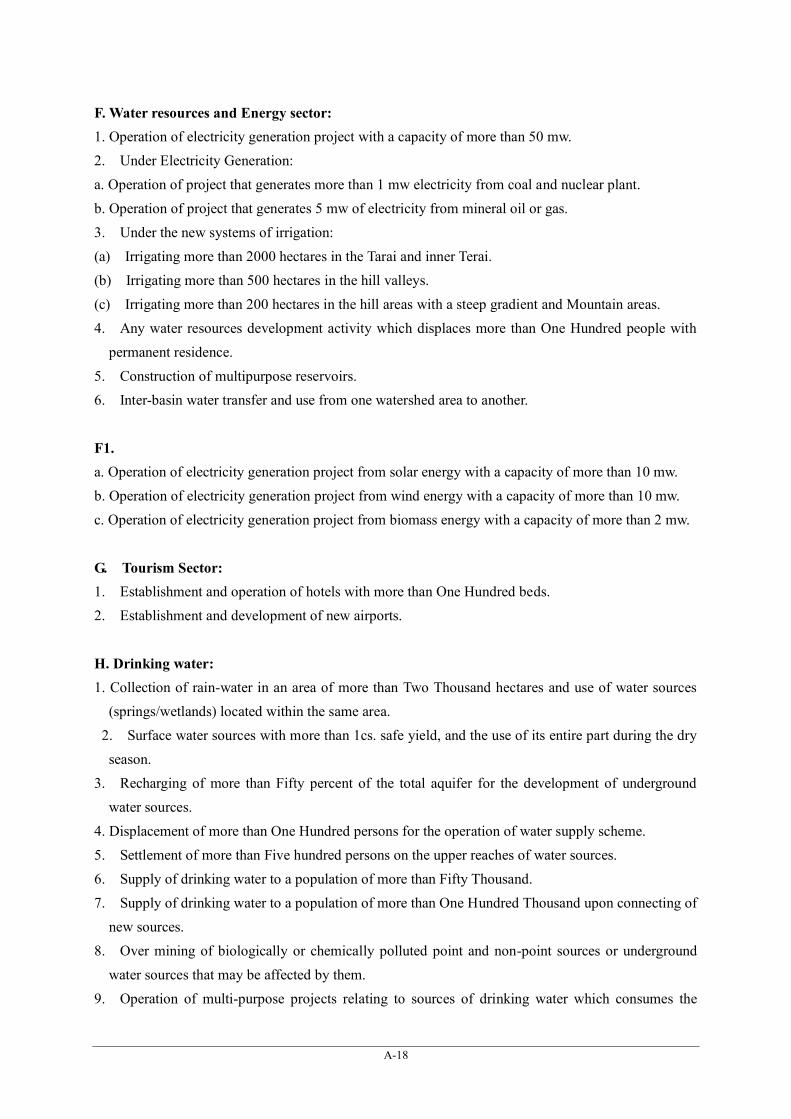
A-18
F. Water resources and Energy sector: 1. Operation of electricity generation project with a capacity of more than 50 mw. 2. Under Electricity Generation: a. Operation of project that generates more than 1 mw electricity from coal and nuclear plant. b. Operation of project that generates 5 mw of electricity from mineral oil or gas. 3. Under the new systems of irrigation: (a) Irrigating more than 2000 hectares in the Tarai and inner Terai. (b) Irrigating more than 500 hectares in the hill valleys. (c) Irrigating more than 200 hectares in the hill areas with a steep gradient and Mountain areas. 4. Any water resources development activity which displaces more than One Hundred people with
permanent residence. 5. Construction of multipurpose reservoirs. 6. Inter-basin water transfer and use from one watershed area to another.
F1. a. Operation of electricity generation project from solar energy with a capacity of more than 10 mw. b. Operation of electricity generation project from wind energy with a capacity of more than 10 mw. c. Operation of electricity generation project from biomass energy with a capacity of more than 2 mw.
G. Tourism Sector: 1. Establishment and operation of hotels with more than One Hundred beds. 2. Establishment and development of new airports.
H. Drinking water: 1. Collection of rain-water in an area of more than Two Thousand hectares and use of water sources
(springs/wetlands) located within the same area. 2. Surface water sources with more than 1cs. safe yield, and the use of its entire part during the dry
season. 3. Recharging of more than Fifty percent of the total aquifer for the development of underground
water sources. 4. Displacement of more than One Hundred persons for the operation of water supply scheme. 5. Settlement of more than Five hundred persons on the upper reaches of water sources. 6. Supply of drinking water to a population of more than Fifty Thousand. 7. Supply of drinking water to a population of more than One Hundred Thousand upon connecting of
new sources. 8. Over mining of biologically or chemically polluted point and non-point sources or underground
water sources that may be affected by them. 9. Operation of multi-purpose projects relating to sources of drinking water which consumes the

A-19
sources at the rate of more than 25 liters per second.
I. Waste Management: 1. Waste management activities to the undertaken with the objective of providing services to a
population of more than Ten Thousand. 2. Following activities relating to waste emitted from houses and residential areas: - (a) Filling of land with more than Five Thousand tons of waste per year. (b) Activities relating of transfer station and resources recovery areas spread over an area of more
than Ten hectares. (c) Selecting, picking, disposing and recycling wastes through chemical, mechanical or biological
techniques' in an area spread over more than Ten hectares. (d) Activity relating to compost plans spread over an area of more than Ten hectors. (e) Burying of waste emitted from an urban area with a population of at least Ten Thousand. 3. Following construction activities relating to hazardous waste of the following nature in any scale:- (a) Construction of waste plant. (b) Construction of waste recovery plant. (c) Constructing of a site for filling accumulating or burying waste. (d) Construction of a site to store the waste. (e) Construction of a waste treatment facility. 4. Following activities relating to lethal waste:- (a) Emission and management of any radioactive Substance with a half age exceeding Twenty Five
years. (b) Emission and management of any lethal chemical with Fifty lethal dose. (c) Final disposal management of biological lethal Substances emitted from Health Center, Hospital,
or Nursing Home with at least Twenty Five beds. (d) Any activating relating to One hectors or more of land and energy for the purpose of incinerating
or recycling any lethal Substance
J. Agriculture Sector: 1. Clearing of forest covering more than One hector in the Hills and Five hector in the Terai and using
it for agricultural proposes. 2. Urbanization plan in cultivable lands. 3. Establishment of Plant for Toxic Pesticide (only those which are listed).
K. Health: 1. Operation of hospitals or nursing homes with more than Hundred beds, or medical profession (study
and teaching also).

A-20
L. If any proposal is to be implemented in the following areas; 1. Historical, Cultural and archeological sites. 2. National Parks, wild life sanctuaries and conservation areas. 3. Areas with main sources of public water supply.
L.1. Operation of any plan, project or programme relating to any developmental work physical activity or change in land use except the proposals mentioned in Clause (a) to Clause (K) and those below the standards of such proposals as well as the proposals below the standards of those mentioned in schedule -1 with a cost of more than Two Hundred Fifty millions.

Data Collection Survey on Thankot Area Road Improvement in Nepal
A-21
ANNEX-6 Table of Contents of MOFSC Project Approval Request
List of Documents required for the Permission from the Ministry of Forest prior to the commencement of EIA. 1. Name of the Project 2. Name of the Proponent and Address 3. Area and alignment coordinate (GPS Points) of the directly affected Forest area. 4. Name and Address of the project area. 5. Type of Forest Conservation Area according to the Forest Act and the Wild Life Conservation Act. 6. Main Flora and Fauna. 7. Estimated Area of the Forest (ha). 8. Sensitive area according to forest, plant resources, diversity and soil conservation, if any. 9. Other issues if any.

Data Collection Survey on Thankot Area Road Improvement in Nepal
A-22
ANNEX-7 Sample Table of Contents of EIA Scoping Document
Source: Scoping Document for Environmental Impact Assessment of Kathmandu – Kulekhani – Hewauda Tunnel (KKHT) Highway Project, Nepal Purwadhar Bikash Company Ltd., January 2013
Chapter 1 Introduction
1.1 General Background 1.2 Name and address of the proponent 1.3 Rationality for conducting EIA 1.4 Objective of scoping 1.5 Importance of EIA study 1.6 Project description 1.7 Project location 1.8 Project area delineation
Chapter 2 Scoping methodology 2.1 Literature review 2.2 Study of topographical maps/other maps 2.3 Public notice and stakeholders response 2.4 Scoping methods adopted 2.5 Brief preliminary review of relevant policies, laws, standards, guidelines, manuals and relevant
documents Chapter 3 Existing environmental condition
3.1 Physical environment 3.1.1 General topography, land use, climate and water, air quality 3.1.2 Geology 3.1.3 Hydrology 3.1.4 Construction material availability situation 3.1.5 Present traffic situation in Kathmandu-Hetuada Sector 3.1.6 Analysis of travel duration 3.1.7 Traffic growth 3.1.8 Existing road network in project affected VDCs 3.1.9 Possible infrastructures that will be affected by the project activities 3.1.10 Land area requirements 3.1.11 Possible labour camp locations 3.1.12 Possible crusher plant location 3.1.13 Spoil management
3.2 Biological environment 3.2.1 Vegetation and forest types 3.2.2 Conservation status 3.2.3 Rare, endangered, endemic, threatened and protected flora and fauna 3.2.4 Existing environmental condition – biological environment
3.3 Socio-economic and cultural environment 3.3.1 Socio-economic information and profile 3.3.2 Infrastructural situation 3.3.3 Outcome of public consultation, interactions and meetings 3.3.4 Opinion of the general public 3.3.5 Summary of participants’ queries and developer’s explanation 3.3.6 Cultural background of the project area
Chapter 4 Environmental issues prioritized for EIA study 4.1 Issues identified by proponent 4.2 Issues raised by stakeholders 4.3 major environmental issues predicted during scoping stage prioritized for EIA 4.4 Beneficial issues prioritized for EIA 4.5 Adverse issues prioritized for EIA
Chapter 5 Work schedule for EIA study

Data Collection Survey on Thankot Area Road Improvement in Nepal
A-23
Annexes 1. Maps 2. Physical data 3. Biological data 4. Social data 5. Project information leaflet 6. Questionnaire for scoping 7. List of participants in interaction meetings 8. Public notice for scoping and notification evidence 9. Documentation of correspondence from stakeholders 10. Study team members and declaration 11. Photographs
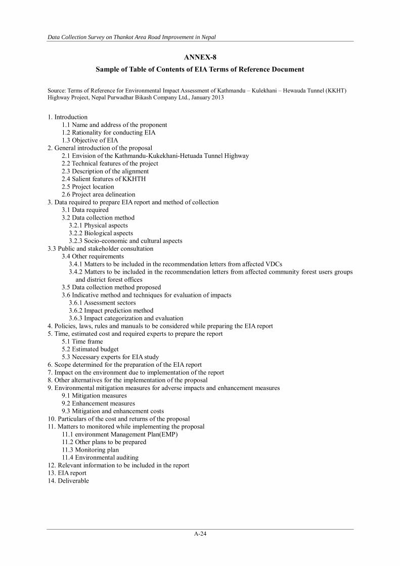
Data Collection Survey on Thankot Area Road Improvement in Nepal
A-24
ANNEX-8 Sample of Table of Contents of EIA Terms of Reference Document
Source: Terms of Reference for Environmental Impact Assessment of Kathmandu – Kulekhani – Hewauda Tunnel (KKHT) Highway Project, Nepal Purwadhar Bikash Company Ltd., January 2013
1. Introduction
1.1 Name and address of the proponent 1.2 Rationality for conducting EIA 1.3 Objective of EIA
2. General introduction of the proposal 2.1 Envision of the Kathmandu-Kukekhani-Hetuada Tunnel Highway 2.2 Technical features of the project 2.3 Description of the alignment 2.4 Salient features of KKHTH 2.5 Project location 2.6 Project area delineation
3. Data required to prepare EIA report and method of collection 3.1 Data required 3.2 Data collection method
3.2.1 Physical aspects 3.2.2 Biological aspects 3.2.3 Socio-economic and cultural aspects
3.3 Public and stakeholder consultation 3.4 Other requirements
3.4.1 Matters to be included in the recommendation letters from affected VDCs 3.4.2 Matters to be included in the recommendation letters from affected community forest users groups
and district forest offices 3.5 Data collection method proposed 3.6 Indicative method and techniques for evaluation of impacts
3.6.1 Assessment sectors 3.6.2 Impact prediction method 3.6.3 Impact categorization and evaluation
4. Policies, laws, rules and manuals to be considered while preparing the EIA report 5. Time, estimated cost and required experts to prepare the report
5.1 Time frame 5.2 Estimated budget 5.3 Necessary experts for EIA study
6. Scope determined for the preparation of the EIA report 7. Impact on the environment due to implementation of the report 8. Other alternatives for the implementation of the proposal 9. Environmental mitigation measures for adverse impacts and enhancement measures
9.1 Mitigation measures 9.2 Enhancement measures 9.3 Mitigation and enhancement costs
10. Particulars of the cost and returns of the proposal 11. Matters to monitored while implementing the proposal
11.1 environment Management Plan(EMP) 11.2 Other plans to be prepared 11.3 Monitoring plan 11.4 Environmental auditing
12. Relevant information to be included in the report 13. EIA report 14. Deliverable

Data Collection Survey on Thankot Area Road Improvement in Nepal
A-25
ANNEX 9
Technical Explanatory Meeting
1. Distribution of Invitation Letter to Concerned Institutions and DOR Staff

Data Collection Survey on Thankot Area Road Improvement in Nepal
A-26

Data Collection Survey on Thankot Area Road Improvement in Nepal
A-27
2. Status and Issues of Road Sector in Nepal

Data Collection Survey on Thankot Area Road Improvement in Nepal
A-28
3. Geological Characteristics of Nepal and Issues on Civil Engineering

Data Collection Survey on Thankot Area Road Improvement in Nepal
A-29
4. Tunnel Construction Techniques in Japan with a focus on NATM

Data Collection Survey on Thankot Area Road Improvement in Nepal
A-30
5. Tunnel Construction Management in Japan

Data Collection Survey on Thankot Area Road Improvement in Nepal
A-31
6. Photographs of Audiences
Data Collection Survey on Thankot Area Road Improvement in Nepal
A-32
ANNEX-10
Observation Visit Tunnel Construction
1. Concept
Designated people from developing countries are invited to Japan to be given opportunities to visit the
tunnel and loop bridge sites that help them useful construction information and techniques.
2. Purpose
・To provide Japanese knowledge and experience with designated people from Nepal.
・To develop an understanding of tunnel technologies, related Japanese techniques and its potentialities.
・To make the future vision of the road development more clear through the observation visit to sites.
3. Participants
Name Organization Position
Tulasi Prasad Sitaula Ministry of Physical Infrastructure and Transport Secretary
Rajendra Prasad Nepal Ministry of Physical Infrastructure and Transport Joint Secretary
Devendra Karki Ministry of Physical Infrastructure and Transport,
Department of Roads Director General
Keahab Kumar Sharma Ministry of Physical Infrastructure and Transport,
Department of Roads Deputy Director General
Daya Kant Jha
Ministry of Physical Infrastructure and Transport,
Department of Roads,
Central Regional Road Directorate
Regional Director
Rupak Rajbhandari Ministry of Physical Infrastructure and Transport,
Department of Roads
Senior Divisional
Engineer
Ashok Tiwari Ministry of Physical Infrastructure and Transport,
Department of Roads
Senior Divisional
Engineer
Satyendra Shakya Ministry of Physical Infrastructure and Transport,
Department of Roads
Senior Divisional
Engineer

Data Collection Survey on Thankot Area Road Improvement in Nepal
A-33
4. Tour Schedule
The observation visit started on 20th May, 2014. Four officials, Secretary and Joint Secretary MoPIT and
Director General and Deputy Director General of DOR left Japan earlier than other officials because of
their schedule. The tour schedule is described as follow.
Tour Schedule
Day Contents
5/20 Leave Nepal
5/21 Arrive at Tokyo
5/22 NATM Technical Presentation, Courtesy Call at JICA HQ
5/23 Observational visit to the tunnel construction site (Hanabuchiyama 2nd Tunnel at Miyagi Pref.)
5/24 Observational visit to Karisaka Tunnel (Saitama and Yamanashi Pref.)
5/25 Observation of road network in Tokyo (four high officials leave Japan at night)
5/26 Observation of road network in Kanagawa
5/27 Leave Japan
5/28 Arrive at Nepal
(1) NATM Technical Presentation
The purpose of NATM Technical Presentation is to introduce the Japanese advanced technology related to
NATM. In contrast to the Technical Presentation held in Kathmandu on 20th April, the NATM Technical
Presentation does not focus on the basic explanation about a series of procedure relating to NATM but
Japanese technological capability for safe and high quality construction.
Time Program
9:45-10:15 Key-note speech: Tunnel Technology in Japan Speaker:Atsushi Kusaka(Public Works Research Institute)
10:15-10:45 Technical Expertise 1: Obayashi Corporation ・Non-core Drilling Exploration Ahead of Face –Tunnel Navi- ・Application of CIM to Tunnel Construction
10:45-11:15 Technical Expertise 2: Shimizu Corporation ・Tunnel Boring Technology of Shimizu
11:15-11:25 Break time
11:25-11:55 Technical Expertise 3: Kumagai Gumi Co., Ltd. ・PSS-Arch Method ・Magaru-Fu Method
11:55-12:25 Technical Expertise 4: Hazama Ando Corporation ・3D-LSTM:3D Laser Scanner Tunnel Measurement System

Data Collection Survey on Thankot Area Road Improvement in Nepal
A-34
・Key-note speech: Tunnel Technology in Japan As the Key-note speech, Mr. Atsushi Kusaka from Public Works Research Institute provided presentation about Tunnel Technology in Japan. It summarized the history of NATM in Japan, Japanese record of NATM construction and latest technologies. It is useful information for Nepali officials to understand that Japan has the sufficient achievement for the tunnel construction.
・Obayashi Corporation (Tunnel Navi and CIM)
Obayashi Corporation provided the presentation about Non-core Drilling Exploration Ahead of Face “Tunnel Navi,” and the application of Construction Information Modeling (CIM). Those are the exploration technique to predict the geological condition ahead of face and detect the water-bearing zone and dewatering, which contributes to the reasonable construction. This presentation provided the opportunity to know the effective use of the information technology.
・Shimizu CorporationTunnel (Boring Technology of Shimizu)
Shimizu Corporation introduced the large tunnel construction projects implemented by its own tunneling
techniques. Especially, The Pahang Selangor Raw Water Tunnel is the impressive project that the three
tunnels, totaling 44.6 km, will address projected water shortages. It is an example which certifies that
Japanese companies have the capability to construct a large-scale tunnel by high technologies.
・

Data Collection Survey on Thankot Area Road Improvement in Nepal
A-35
Kumagai Gumi Co., Ltd. (PSS-Arch Method and Magaru-Fu Method) Kumagai Gumi Co., Ltd. introduced two types of the supplementary construction method which is usually
used for measures against the face instability, spring water and ground surface subsidence. For the tunnel construction in Nepal where the geological condition is complicated and weak, it has the importance for the safe construction. Therefore, this presentation provided the opportunity to know how to do reasonable design and construction by the usage of the supplementary construction method.
・Hazama Ando Corporation (3D-LSTM) Hazama Ando Corporation introduced the 3D Laser Scanner Tunnel Measurement System (3D-LSTM).
This system is the methodology for tunnel displacement tracking based on three dimensional laser scanning. It can measure the cross-sectional shape of tunnels, and it can also detect the direction and the amount of displacements at any point of tunnel wall. 3D-LSTM is an effective tool for the expectation of deformation risk. This presentation provided the practical example of the 3d application for NATM construction.

Data Collection Survey on Thankot Area Road Improvement in Nepal
A-36
(2) Observational Visit
Hanabuchiyama Second Tunnel (Miyagi Pref., Tōhoku region)
The Hanabuchiyama Second Tunnel (1,194m in length) is a part of Hanabuchiyama Bypass. On the
observational visit, the construction manager gave the detailed explanation about the construction method
“NATM” and the safety management. This visit provided the opportunity to understand a series of
procedures relating to NATM construction and the importance pf the safety management.

Data Collection Survey on Thankot Area Road Improvement in Nepal
A-37
Karisaka Tunnel (Saitama Pref. & Yamanashi Pref.)
Karisaka Tunnel (6,625m in length) is a Japanese toll tunnel that opened 1998. It is the longest
mountainous tunnel of Japanese National Route. The serious accident still has not occurred since the
inauguration because of thorough safety operation and management. On the observational visit, the director
of the Karisaka Tunnel Office provided the detailed explanation about the operation and management
system and related devices. The knowledge obtained through this visit is expected to contribute the
prevention of the accident in a tunnel.

Data Collection Survey on Thankot Area Road Improvement in Nepal
A-38
Characteristic other structures
Observational visit was implemented at other characteristic structures. These structures are not tunnels, but
there are suitable examples to experience the Japanese technology for road construction.
・Ōhashi Junction (Tokyo)
Ōhashi Junction is the reinforced concrete structure which
connects the underground tunnel and elevated road. This
structure applies the unique design, a tunnel with the shape of
quadruple loop bridge To reduce the impact on the
surrounding environment, such as air pollution and noise
pollution, the ground area is covered by wall (Tunnel).
Port of Tokyo Connector Bridge (Rainbow Bridge, Tokyo)
Port of Tokyo Connector Bridge, known as Rainbow Bridge, is
composed of the suspension bridge and both approach sides.
One side of approach section is constructed with a loop bridge
to secure the height for ship crossing under the bridge. Thus,
the length of the loop bridge reaches more than 1,000m.
Tokyo Bay Aqualine (Tokyo and Chiba Prefecture)
The Tokyo Bay Aqualine, is a 15.1 km marine crossing
through the middle of Tokyo Bay connecting Kawasaki City in
Kanagawa Prefecture with Kisarazu City in Chiba Prefecture.
The Aqualine consists of a 9.5-km shield tunnel (the Tokyo
Bay Tunnel) and a 4.4-km bridge from an artificial island to
the Kisarazu landing. The tunnel diameter is the world's largest
for an underwater shield tunnel used for motor vehicle traffic.
Saitama Raiden Todoroki Bridge (Saitama Pref.)
Saitama Raiden Todoroki Bridge is constructed as a divided
road, prior to the construction of Takizawa Dam. This bridge is
composed of three sections, such as, Otaki bridge section,
Todoroki bridge section, and the intermediate section (curving
section). These structures are connected by solving the height
difference about 125m.

Data Collection Survey on Thankot Area Road Improvement in Nepal
A-39
ANNEX-11
Study Team Member List
Data Collection Survey on Thankot Area Road Improvement in Nepal
List of JICA Study Team Members
Name:
Company:
Assignment
YAJIMA Hiroshi
TONICHI ENGINERRING CONSULTANTS, INC.
Team Leader / Alignment Planning 1 (Structure) / Transportation Planning
Name:
Company:
Assignment
SHRESTHA Robinson
CTI Engineering International Co., Ltd.
Subleader / Alignment Planning 2 (Road) / Road Planning
Name:
Company:
Assignment
MORI Shinsuke
CTI Engineering International Co., Ltd.
Tunnel Planning
Name:
Company:
Assignment
NAKAJIMA Fumiki
CTI Engineering International Co., Ltd.
Geology / Slope Stabilization
Name:
Company:
Assignment
IDE Kakiko
CTI Engineering International Co., Ltd. (POLYTECH ADD)
Environmental and Social Consideration
Name:
Company:
Assignment
CHIBA Nobuyuki
TONICHI ENGINERRING CONSULTANTS, INC. (TOSTEMS, INC)
Hydrological Survey / Recommissioning