
CHAPTER 6 COMPASSES - Maritime Safety Information
17
81 CHAPTER 6 COMPASSES INTRODUCTION 600. Changes in Compass Technologies This chapter discusses the major types of compasses available to the navigator, their operating principles, their capabilities, and limitations of their use. As with other aspects of navigation, technology is rapidly revolutionizing the field of compasses. Amazingly, after at least a millennia of constant use, it is now possible (however advisable it may or may not be aboard any given vessel) to dispense with the traditional magnetic compass. For much of maritime history the only heading reference for navigators has been the magnetic compass. A great deal of effort and expense has gone into understanding the magnetic compass scientifically and making it as accurate as possible through elaborate compensation techniques. The introduction of the electro-mechanical gyrocompass relegated the magnetic compass to backup status for many large vessels. Later came the development of inertial navigation systems based on gyroscopic principles. The interruption of electrical power to the gyrocompass or inertial navigator, mechanical failure, or its physical destruction would instantly elevate the magnetic compass to primary status for most vessels. New technologies are both refining and replacing the magnetic compass as a heading reference and navigational tool. Although a magnetic compass for backup is certainly advisable, today’s navigator can safely avoid nearly all of the effort and expense associated with the binnacle- mounted magnetic compass, its compensation, adjustment, and maintenance. Similarly, electro-mechanical gyrocompasses are being supplanted by far lighter, cheaper, and more dependable ring laser gyrocompasses. These devices do not operate on the principle of the gyroscope (which is based on Newton’s laws of motion), but instead rely on the principles of electromagnetic energy and wave theory. Magnetic flux gate compasses, while relying on the earth’s magnetic field for reference, have no moving parts and can compensate themselves, adjusting for both deviation and variation to provide true heading, thus completely eliminating the process of compass correction. To the extent that one depends on the magnetic compass for navigation, it should be checked regularly and adjusted when observed errors exceed certain minimal limits, usually a few degrees for most vessels. Compensation of a magnetic compass aboard vessels expected to rely on it offshore during long voyages is best left to professionals. However, this chapter will present enough material for the competent navigator to do a passable job. Whatever type of compass is used, it is advisable to check it periodically against an error free reference to determine its error. This may be done when steering along any range during harbor and approach navigation, or by aligning any two charted objects and finding the difference between their observed and charted bearings. When navigating offshore, the use of azimuths and amplitudes of celestial bodies will also suffice, a subject covered in Chapter 17. MAGNETIC COMPASSES 601. The Magnetic Compass and Magnetism The principle of the present day magnetic compass is no different from that of the compasses used by ancient mariners. The magnetic compass consists of a magnetized needle, or an array of needles, allowed to rotate in the horizontal plane. The superiority of present day magnetic compasses over ancient ones results from a better knowledge of the laws of magnetism which govern the behavior of the compass and from greater precision in design and construction. Any magnetized piece of metal will have regions of concentrated magnetism called poles. Any such magnet will have at least two poles of opposite polarity. Magnetic force (flux) lines connect one pole of such a magnet with the other pole. The number of such lines per unit area represents the intensity of the magnetic field in that area. If two magnets are placed close to each other, the like poles will repel each other and the unlike poles will attract each other. Magnetism can be either permanent or induced.A bar having permanent magnetism will retain its magnetism when it is removed from a magnetizing field. A bar having induced magnetism will lose its magnetism when removed
Transcript of CHAPTER 6 COMPASSES - Maritime Safety Information
rerenot
ons
egothss
ticndal
s.elsst
nta
ckitsingo
eirtheso
icthea.kect
mged
CHAPTER 6
COMPASSES
INTRODUCTION
600. Changes in Compass Technologies
This chapter discusses the major types of compassesavailable to the navigator, their operating principles,their capabilities, and limitations of their use. Aswithother aspects of navigation, technology is rapidlyrevolutionizing the field of compasses. Amazingly, after atleast a millennia of constant use, it is now possible(however advisable it may or may not be aboard any givenvessel) to dispense with the traditional magnetic compass.
For much of maritime history the only headingreference for navigators has been the magnetic compass. Agreat deal of effort and expense has gone intounderstanding the magnetic compass scientifically andmaking it as accurate as possible through elaboratecompensation techniques.
The introduction of the electro-mechanicalgyrocompass relegated the magnetic compass to backupstatus for many large vessels. Later came the developmentof inertial navigation systems based on gyroscopicprinciples. The interruption of electrical power to thegyrocompass or inertial navigator, mechanical failure, or itsphysical destruction would instantly elevate the magneticcompass to primary status for most vessels.
New technologies are both refining and replacing themagnetic compass as a heading reference and navigationaltool. Although a magnetic compass for backup is certainlyadvisable, today’s navigator can safely avoid nearly all ofthe effort and expense associated with the binnacle-mounted magnetic compass, its compensation, adjustment,
and maintenance.Similarly, electro-mechanical gyrocompasses a
being supplanted by far lighter, cheaper, and modependable ring laser gyrocompasses. These devices dooperate on the principle of the gyroscope (which is basedNewton’s laws of motion), but instead rely on the principleof electromagnetic energy and wave theory.
Magnetic flux gate compasses, while relying on thearth’s magnetic field for reference, have no movinparts and can compensate themselves, adjusting for bdeviation and variation to provide true heading, thucompletely eliminating the process of compascorrection.
To the extent that one depends on the magnecompass for navigation, it should be checked regularly aadjusted when observed errors exceed certain minimlimits, usually a few degrees for most vesselCompensation of a magnetic compass aboard vessexpected to rely on it offshore during long voyages is beleft to professionals. However, this chapter will preseenough material for the competent navigator to dopassable job.
Whatever type of compass is used, it is advisable to cheit periodically against an error free reference to determineerror. This may be done when steering along any range durharbor and approach navigation, or by aligning any twcharted objects and finding the difference between thobserved and charted bearings. When navigating offshore,use of azimuths and amplitudes of celestial bodies will alsuffice, a subject covered in Chapter 17.
MAGNETIC COMPASSES
601. The Magnetic Compass and Magnetism
The principle of the present day magnetic compass isno different from that of the compasses used by ancientmariners. The magnetic compass consists of a magnetizedneedle, or an array of needles, allowed to rotate in thehorizontal plane. The superiority of present day magneticcompasses over ancient ones results from a betterknowledge of the laws of magnetism which govern thebehavior of the compass and from greater precision indesign and construction.
Any magnetized piece of metal will have regions of
concentrated magnetism calledpoles. Any such magnetwill have at least two poles of opposite polarity. Magnetforce (flux) lines connect one pole of such a magnet withe other pole. The number of such lines per unit arrepresents the intensity of the magnetic field in that area
If two magnets are placed close to each other, the lipoles will repel each other and the unlike poles will attraeach other.
Magnetism can be eitherpermanent or induced. Abar having permanent magnetism will retain its magnetiswhen it is removed from a magnetizing field. A bar havininduced magnetism will lose its magnetism when remov
81
82 COMPASSES
es
fteddddyinited
chbuted
entbyof
uententent
t,ip’s
from the magnetizing field. Whether or not a bar will retainits magnetism on removal from the magnetizing field willdepend on the strength of that field, the degree of hardnessof the iron (retentivity), and upon the amount of physicalstress applied to the bar while in the magnetizing field. Theharder the iron, the more permanent will be the magnetismacquired.
602. Terrestrial Magnetism
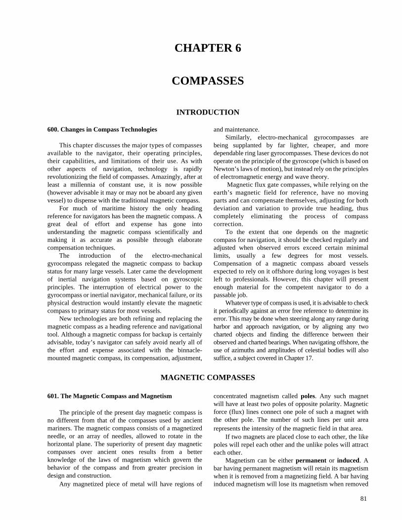
Consider the Earth as a huge magnet surrounded bylines of magnetic flux connecting its twomagnetic poles.These magnetic poles are near, but not coincidental with,the Earth’s geographic poles. Since the north seeking end ofa compass needle is conventionally called thenorth pole,or positive pole, it must therefore be attracted to asouthpole, ornegative pole.
Figure 602a illustrates the Earth and its surroundingmagnetic field. The flux lines enter the surface of the Earthat different angles to the horizontal at different magneticlatitudes. This angle is called theangle of magnetic dip,θ, and increases from 0° at the magnetic equator to 90° atthe magnetic poles. The total magnetic field is generallyconsidered as having two components: H, the horizontalcomponent; and Z, the vertical component. Thesecomponents change as the angleθ changes, such that H isat its maximum at the magnetic equator and decreases in thedirection of either pole, while Z is zero at the magneticequator and increases in the direction of either pole.
Since the magnetic poles of the Earth do not coincidewith the geographic poles, a compass needle in line with theEarth’s magnetic field will not indicate true north, butmagnetic north. The angular difference between the truemeridian (great circle connecting the geographic poles) andthe magnetic meridian (direction of the lines of magneticflux) is calledvariation . This variation has different valuesat different locations on the Earth. These values of magneticvariation may be found on pilot charts and on the compassrose of navigational charts.
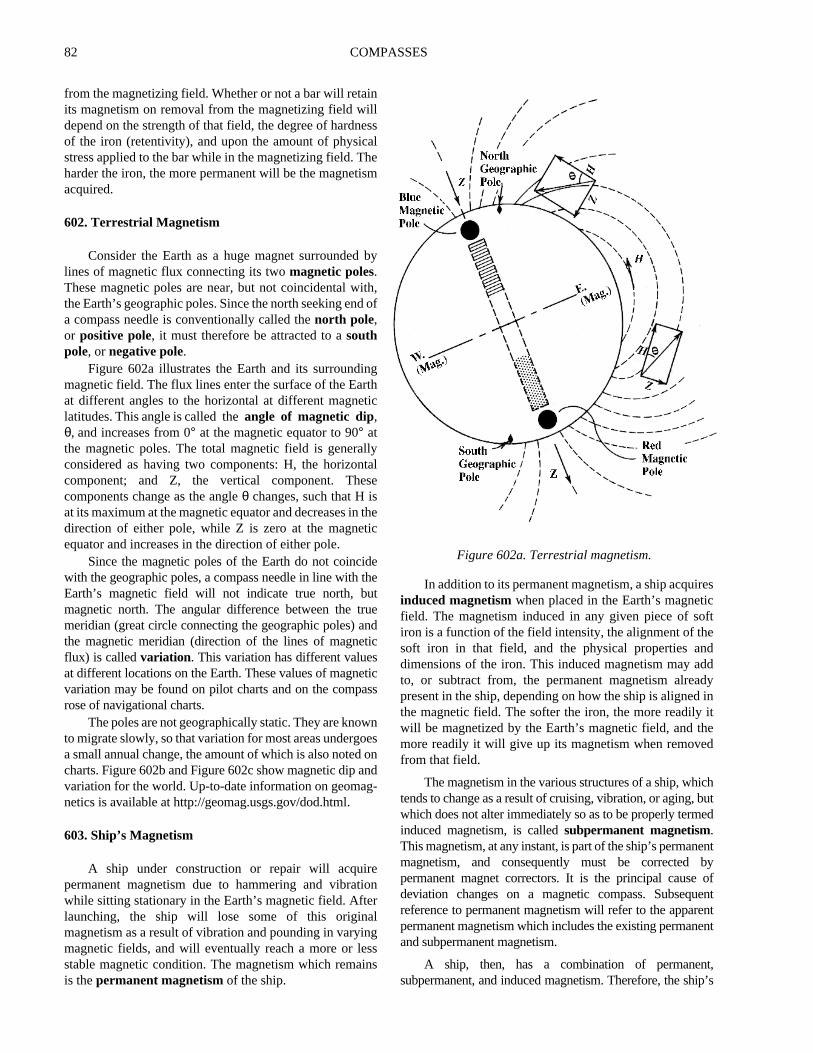
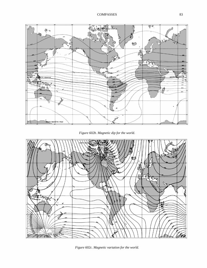
The poles are not geographically static. They are knownto migrate slowly, so that variation for most areas undergoesa small annual change, the amount of which is also noted oncharts. Figure 602b and Figure 602c show magnetic dip andvariation for the world. Up-to-date information on geomag-netics is available at http://geomag.usgs.gov/dod.html.
603. Ship’s Magnetism
A ship under construction or repair will acquirepermanent magnetism due to hammering and vibrationwhile sitting stationary in the Earth’s magnetic field. Afterlaunching, the ship will lose some of this originalmagnetism as a result of vibration and pounding in varyingmagnetic fields, and will eventually reach a more or lessstable magnetic condition. The magnetism which remainsis thepermanent magnetism of the ship.
In addition to its permanent magnetism, a ship acquirinduced magnetismwhen placed in the Earth’s magneticfield. The magnetism induced in any given piece of soiron is a function of the field intensity, the alignment of thsoft iron in that field, and the physical properties andimensions of the iron. This induced magnetism may ato, or subtract from, the permanent magnetism alreapresent in the ship, depending on how the ship is alignedthe magnetic field. The softer the iron, the more readilywill be magnetized by the Earth’s magnetic field, and thmore readily it will give up its magnetism when removefrom that field.
The magnetism in the various structures of a ship, whitends to change as a result of cruising, vibration, or aging,which does not alter immediately so as to be properly terminduced magnetism, is calledsubpermanent magnetism.This magnetism, at any instant, is part of the ship’s permanmagnetism, and consequently must be correctedpermanent magnet correctors. It is the principal causedeviation changes on a magnetic compass. Subseqreference to permanent magnetism will refer to the apparpermanent magnetism which includes the existing permanand subpermanent magnetism.
A ship, then, has a combination of permanensubpermanent, and induced magnetism. Therefore, the sh
Figure 602a. Terrestrial magnetism.
COMPASSES 83
Figure 602b. Magnetic dip for the world.
Figure 602c. Magnetic variation for the world.
84 COMPASSES
asillts;gleyillssanseflds
.
apparent permanent magnetic condition is subject to changefrom deperming, shocks, welding, and vibration. The ship’sinduced magnetism will vary with the Earth’s magnetic fieldstrength and with the alignment of the ship in that field.
604. Magnetic Adjustment
A narrow rod of soft iron, placed parallel to the Earth’shorizontal magnetic field, H, will have a north pole induced inthe end toward the north geographic pole and a south poleinduced in the end toward the south geographic pole. This samerod in a horizontal plane, but at right angles to the horizontalEarth’s field, would have no magnetism induced in it, becauseits alignment in the magnetic field precludes linearmagnetization, if the rod is of negligible cross section. Shouldthe rod be aligned in some horizontal direction between thoseheadings which create maximum and zero induction, it wouldbe induced by an amount which is a function of the angle ofalignment. However, if a similar rod is placed in a verticalposition in northern latitudes so as to be aligned with the verticalEarth’s field Z, it will have a south pole induced at the upper endand a north pole induced at the lower end. These polarities ofvertical induced magnetization will be reversed in southernlatitudes.
The amount of horizontal or vertical induction in suchrods, or in ships whose construction is equivalent tocombinations of such rods, will vary with the intensity of Hand Z, heading, and heel of the ship.
The magnetic compass must be corrected for thevessel’s permanent and induced magnetism so that itsoperation approximates that of a completely nonmagneticvessel. Ship’s magnetic conditions create magneticcompass deviations and sectors of sluggishness andunsteadiness.Deviation is defined as deflection right or leftof the magnetic meridian caused by magnetic properties ofthe vessel. Adjusting the compass consists of arrangingmagnetic and soft ironcorrectors near the compass so thattheir effects are equal and opposite to the effects of themagnetic material in the ship.
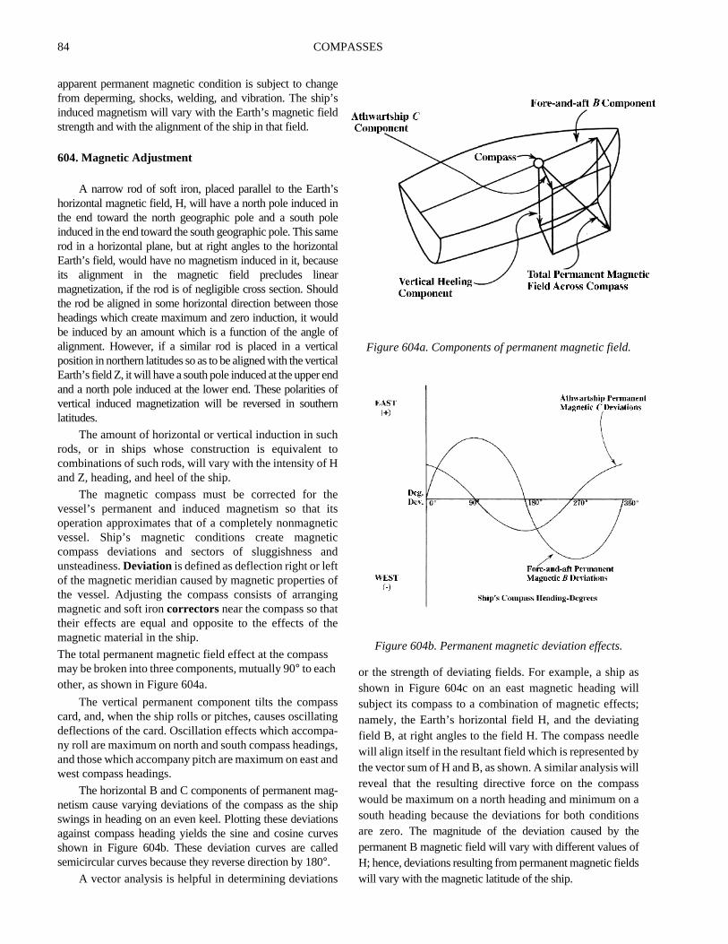
The total permanent magnetic field effect at the compassmay be broken into three components, mutually 90° to eachother, as shown in Figure 604a.
The vertical permanent component tilts the compasscard, and, when the ship rolls or pitches, causes oscillatingdeflections of the card. Oscillation effects which accompa-ny roll are maximum on north and south compass headings,and those which accompany pitch are maximum on east andwest compass headings.
The horizontal B and C components of permanent mag-netism cause varying deviations of the compass as the shipswings in heading on an even keel. Plotting these deviationsagainst compass heading yields the sine and cosine curvesshown in Figure 604b. These deviation curves are calledsemicircular curves because they reverse direction by 180°.
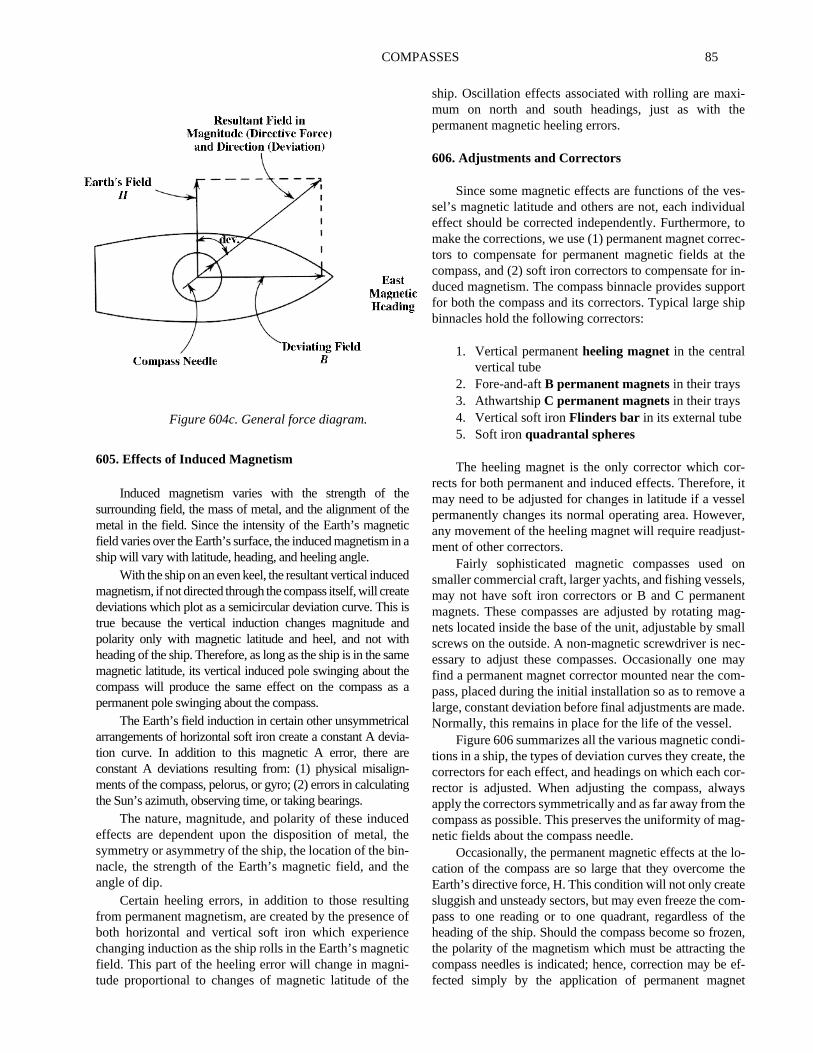
A vector analysis is helpful in determining deviations
or the strength of deviating fields. For example, a shipshown in Figure 604c on an east magnetic heading wsubject its compass to a combination of magnetic effecnamely, the Earth’s horizontal field H, and the deviatinfield B, at right angles to the field H. The compass needwill align itself in the resultant field which is represented bthe vector sum of H and B, as shown. A similar analysis wreveal that the resulting directive force on the compawould be maximum on a north heading and minimum onsouth heading because the deviations for both conditioare zero. Themagnitude of the deviation caused by thpermanent B magnetic field will vary with different values oH; hence, deviations resulting from permanent magnetic fiewill vary with the magnetic latitude of the ship.
Figure 604a. Components of permanent magnetic field
Figure 604b. Permanent magnetic deviation effects.
COMPASSES 85
i-e
s-altoec-
thein-ortip
r-, itseler,t-
onls,ntag-allc-
maym-a
de.
di-theor-ys
heag-
lo-the
om-theen,eef-
et
605. Effects of Induced Magnetism
Induced magnetism varies with the strength of thesurrounding field, the mass of metal, and the alignment of themetal in the field. Since the intensity of the Earth’s magneticfield varies over the Earth’s surface, the induced magnetism in aship will vary with latitude, heading, and heeling angle.
With the ship on an even keel, the resultant vertical inducedmagnetism, if not directed through the compass itself, will createdeviations which plot as a semicircular deviation curve. This istrue because the vertical induction changes magnitude andpolarity only with magnetic latitude and heel, and not withheading of the ship. Therefore, as long as the ship is in the samemagnetic latitude, its vertical induced pole swinging about thecompass will produce the same effect on the compass as apermanent pole swinging about the compass.
The Earth’s field induction in certain other unsymmetricalarrangements of horizontal soft iron create a constant A devia-tion curve. In addition to this magnetic A error, there areconstant A deviations resulting from: (1) physical misalign-ments of the compass, pelorus, or gyro; (2) errors in calculatingthe Sun’s azimuth, observing time, or taking bearings.
The nature, magnitude, and polarity of these inducedeffects are dependent upon the disposition of metal, thesymmetry or asymmetry of the ship, the location of the bin-nacle, the strength of the Earth’s magnetic field, and theangle of dip.
Certain heeling errors, in addition to those resultingfrom permanent magnetism, are created by the presence ofboth horizontal and vertical soft iron which experiencechanging induction as the ship rolls in the Earth’s magneticfield. This part of the heeling error will change in magni-tude proportional to changes of magnetic latitude of the
ship. Oscillation effects associated with rolling are maxmum on north and south headings, just as with thpermanent magnetic heeling errors.
606. Adjustments and Correctors
Since some magnetic effects are functions of the vesel’s magnetic latitude and others are not, each individueffect should be corrected independently. Furthermore,make the corrections, we use (1) permanent magnet corrtors to compensate for permanent magnetic fields atcompass, and (2) soft iron correctors to compensate forduced magnetism. The compass binnacle provides suppfor both the compass and its correctors. Typical large shbinnacles hold the following correctors:
1. Vertical permanentheeling magnetin the centralvertical tube
2. Fore-and-aftB permanent magnets in their trays3. AthwartshipC permanent magnets in their trays4. Vertical soft ironFlinders bar in its external tube5. Soft ironquadrantal spheres
The heeling magnet is the only corrector which corects for both permanent and induced effects. Thereforemay need to be adjusted for changes in latitude if a vespermanently changes its normal operating area. Howevany movement of the heeling magnet will require readjusment of other correctors.
Fairly sophisticated magnetic compasses usedsmaller commercial craft, larger yachts, and fishing vessemay not have soft iron correctors or B and C permanemagnets. These compasses are adjusted by rotating mnets located inside the base of the unit, adjustable by smscrews on the outside. A non-magnetic screwdriver is neessary to adjust these compasses. Occasionally onefind a permanent magnet corrector mounted near the copass, placed during the initial installation so as to removelarge, constant deviation before final adjustments are maNormally, this remains in place for the life of the vessel.
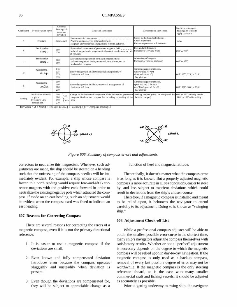
Figure 606 summarizes all the various magnetic contions in a ship, the types of deviation curves they create,correctors for each effect, and headings on which each crector is adjusted. When adjusting the compass, alwaapply the correctors symmetrically and as far away from tcompass as possible. This preserves the uniformity of mnetic fields about the compass needle.
Occasionally, the permanent magnetic effects at thecation of the compass are so large that they overcomeEarth’s directive force, H. This condition will not only createsluggish and unsteady sectors, but may even freeze the cpass to one reading or to one quadrant, regardless ofheading of the ship. Should the compass become so frozthe polarity of the magnetism which must be attracting thcompass needles is indicated; hence, correction may befected simply by the application of permanent magn
Figure 604c. General force diagram.
86 COMPASSES
orticteerld
antndg
toe,ithnteticess,
beg
llered
r
correctors to neutralize this magnetism. Whenever such ad-justments are made, the ship should be steered on a headingsuch that the unfreezing of the compass needles will be im-mediately evident. For example, a ship whose compass isfrozen to a north reading would require fore-and-aft B cor-rector magnets with the positive ends forward in order toneutralize the existing negative pole which attracted the com-pass. If made on an east heading, such an adjustment wouldbe evident when the compass card was freed to indicate aneast heading.
607. Reasons for Correcting Compass
There are several reasons for correcting the errors of amagnetic compass, even if it is not the primary directionalreference:
1. It is easier to use a magnetic compass if thedeviations are small.
2. Even known and fully compensated deviationintroduces error because the compass operatessluggishly and unsteadily when deviation ispresent.
3. Even though the deviations are compensated for,they will be subject to appreciable change as a
function of heel and magnetic latitude.
Theoretically, it doesn’t matter what the compass erris as long as it is known. But a properly adjusted magnecompass is more accurate in all sea conditions, easier to sby, and less subject to transient deviations which couresult in deviations from the ship’s chosen course.
Therefore, if a magnetic compass is installed and meto be relied upon, it behooves the navigator to attecarefully to its adjustment. Doing so is known as “swinginship.”
608. Adjustment Check-off List
While a professional compass adjuster will be ableobtain the smallest possible error curve in the shortest timmany ship’s navigators adjust the compass themselves wsatisfactory results. Whether or not a “perfect” adjustmeis necessary depends on the degree to which the magncompass will be relied upon in day-to-day navigation. If thmagnetic compass is only used as a backup comparemoval of every last possible degree of error may notworthwhile. If the magnetic compass is the only steerinreference aboard, as is the case with many smacommercial craft and fishing vessels, it should be adjustas accurately as possible.
Prior to getting underway to swing ship, the navigato
Coefficient Type deviation curve
Compassheadings ofmaximumdeviation
Causes of such errors Correctors for such errorsMagnetic or compassheadings on which toapply correctors
A Constant. Same on all. Human-error in calculations _ _ _ _ _ _ _ _ _ _ _ _ _ _ _ Physical-compass, gyro, pelorus alignment _ _ _ _ _ _ _ _ _Magnetic-unsymmetrical arrangements of horiz. soft iron.
Check methods and calculationsCheck alignmentsRare arrangement of soft iron rods.
Any.
BSemicircular
090˚270˚
Fore-and-aft component of permanent magnetic field _ _ _ _ _Induced magnetism in unsymmetrical vertical iron forward or aftof compass.
Fore-and-aftB magnetsFlinders bar (forward or aft) 090˚ or 270˚.
CSemicircular
000˚180˚
Athwartship component of permanent magnetic field- - - - - - -Induced magnetism in unsymmetrical vertical iron port orstarboard of compass.
AthwartshipC magnetsFlinders bar (port or starboard) 000˚ or 180˚.
D
Quadrantral 045˚135˚225˚315˚
Induced magnetism in all symmetrical arrangements ofhorizontal soft iron.
Spheres on appropriate axis.(athwartship for +D)(fore and aft for -D)See sketch a
045˚, 135˚, 225˚, or 315˚.
EQuadrantral 000˚
090˚180˚270˚
Induced magnetism in all unsymmetrical arrangements ofhorizontal soft iron.
Spheres on appropriate axis.(port fwd.-stb’d for +E)(stb’d fwd.-port aft for -E)See sketch b
000˚, 090˚, 180˚, or 270˚.
Heeling
Oscillations with rollor pitch.
Deviations withconstant list.
000˚180˚090˚270˚
} roll
} pitch
Change in the horizontal component of the induced or permanentmagnetic fields at the compass due to rolling or pitching of theship.
Heeling magnet (must be readjusted forlatitude changes).
090˚ or 270˚ with dip needle.000˚ or 180˚ while rolling.
Figure 606. Summary of compass errors and adjustments.
φsin .
φcos .
2φ .sin
2φ .cos
Deviation A B φ C φ D+cos+sin+= 2φ E 2φ φ compass heading=( )cos+sin
COMPASSES 87
d)forrystry, anal
ns
e.
.
e
e
m
in
ds,het
geg,slych
gsndnshehe
ssge
ral
must ensure that the process will proceed as expeditiouslyas possible by preparing the vessel and compass. Thefollowing tests and adjustment can be done at dockside,assuming that the compass has been installed andmaintained properly. Initial installation and adjustmentshould be done by a professional compass technicianduring commissioning.
1. Check for bubbles in the compass bowl. Fluid maybe added through the filling plug if necessary.Large bubbles indicate serious leakage, indicatingthat the compass should be taken to a professionalcompass repair facility for new gaskets.
2. Check for free movement of gimbals. Clean anydust or dirt from gimbal bearings and lubricatethem as recommended by the maker.
3. Check for magnetization of the quadrantal spheresby moving them close to the compass and rotatingthem. If the compass needle moves more than 2degrees, the spheres must be annealed to removetheir magnetism. Annealing consists of heating thespheres to a dull red color in a non-magnetic areaand allowing them to cool slowly to ambienttemperature.
4. Check for magnetization of the Flinders bar byinverting it, preferably with the ship on an E/Wheading. If the compass needle moves more than 2degrees the Flinders bar must be annealed.
5. Synchronize the gyro repeaters with the mastergyro so courses can be steered accurately.
6. Assemble past documentation relating to thecompass and its adjustment. Have the ship’sdegaussing folder ready.
7. Ensure that every possible metallic object is stowedfor sea. All guns, doors, booms, and other movablegear should be in its normal seagoing position. Allgear normally turned on such as radios, radars,loudspeakers, etc. should be on while swingingship.
8. Have the International Code flags Oscar-Quebecready to fly.
Once underway to swing ship, the followingprocedures will expedite the process. Choose the besthelmsman aboard and instruct him to steer each course assteadily and precisely as possible. Each course should besteered steadily for at least two minutes before anyadjustments are made to remove Gaussin error. Be sure thegyro is set for the mean speed and latitude of the ship.
The navigator (or compass adjuster if one is employeshould have a pelorus and a table of azimuths preparedchecking the gyro, but the gyrocompass will be the primasteering reference. Normally the adjuster will requecourses and move the magnets as he feels necessaprocess much more an art than a science. If a professioadjuster is not available, use the following sequence:
1. If there is a sea running, steer course 000° andadjust the heeling magnet to decrease oscillatioto a minimum.
2. Come to course 090°. When steady on course 090°,for at least two minutes, insert, remove, or movfore-and-aft B magnets to remove ALL deviation
3. Come to a heading of 180°. Insert, remove, or moveathwartships C magnets to remove ALL deviation
4. Come to 270° and move the B magnets to removone half of the deviation.
5. Come to 000° and move the C magnets to removone half of the deviation.
6. Come to 045° (or any intercardinal heading) andmove the quadrantal spheres toward or away frothe compass to minimize any error.
7. Come to 135° (or any intercardinal heading 90°from the previous course) and move the spheresor out to remove one half of the observed error.
8. Steer the ship in turn on each cardinal anintercardinal heading around the compasrecording the error at each heading called for on tdeviation card. If plotted, the errors should ploroughly as a sine curve about the 0° line.
If necessary, repeat steps 1-8. There is no averaerror, for each ship is different, but generally speakinerrors of more than a few degrees, or errors which serioudistort the sine curve, indicate a magnetic problem whishould be addressed.
Once the compass has been swung, tighten all fittinand carefully record the placement of all magnets acorrectors. Finally, swing for residual degaussed deviatiowith the degaussing circuits energized and record tdeviations on the deviation card. Post this card near tchart table for ready reference by the navigation team.
Once properly adjusted, the magnetic compadeviations should remain constant until there is some chanin the magnetic condition of the vessel resulting frommagnetic treatment, shock, vibration, repair, or structuchanges. Transient deviations are discussed below.
88 COMPASSES
’sdss,e
ns.yofng
erofng.in
ingetheat
g
eireingv-
ldsthetedse
by, aitse
edles,
ofas
609. Sources of Transient Error
The ship must be in seagoing trim and condition toproperly compensate a magnetic compass. Any movementof large metal objects or the energizing of any electricalequipment in the vicinity of the compass can cause errors.If in doubt about the effect of any such changes,temporarily move the gear or cycle power to the equipmentwhile observing the compass card while on a steadyheading. Preferably this should be done on two differentheadings 90° apart, since the compass might be affected onone heading and not on another.
Some magnetic items which cause deviations if placedtoo close to the compass are as follows:
1. Movable guns or weapon loads2. Magnetic cargo3. Hoisting booms4. Cable reels5. Metal doors in wheelhouse6. Chart table drawers7. Movable gyro repeater8. Windows and ports9. Signal pistols racked near compass10. Sound powered telephones11. Magnetic wheel or rudder mechanism12. Knives or tools near binnacle13. Watches, wrist bands, spectacle frames14. Hat grommets, belt buckles, metal pencils15. Heating of smoke stack or exhaust pipes16. Landing craft
Some electrical items which cause variable deviationsif placed too close to the compass are:
1. Electric motors2. Magnetic controllers3. Gyro repeaters4. Nonmarried conductors5. Loudspeakers6. Electric indicators7. Electric welding8. Large power circuits
9. Searchlights or flashlights10. Electrical control panels or switches11. Telephone headsets12. Windshield wipers13. Rudder position indicators, solenoid type14. Minesweeping power circuits15. Engine order telegraphs16. Radar equipment17. Magnetically controlled switches18. Radio transmitters19. Radio receivers20. Voltage regulators
Another source of transient deviation is theretentiveerror . This error results from the tendency of a shipstructure to retain induced magnetic effects for short perioof time. For example, a ship traveling north for several dayespecially if pounding in heavy seas, will tend to retain somfore-and-aft magnetism induced under these conditioAlthough this effect is transient, it may cause slightlincorrect observations or adjustments. This same typeerror occurs when ships are docked on one heading for loperiods of time. A short shakedown, with the ship on othheadings, will tend to remove such errors. A similar sortresidual magnetism is left in many ships if the degaussicircuits are not secured by the correct reversal sequence
A source of transient deviation somewhat shorterduration than retentive error is known asGaussin error.This error is caused by eddy currents set up by a changnumber of magnetic lines of force through soft iron as thship changes heading. Due to these eddy currents,induced magnetism on a given heading does not arriveits normal value until about 2 minutes after changincourse.
Deperming and other magnetic treatment will changthe magnetic condition of the vessel and therefore requcompass readjustment. The decaying effects of depermcan vary. Therefore, it is best to delay readjustment for seeral days after such treatment. Since the magnetic fieused for such treatments are sometimes rather large atcompass locations, the Flinders bar, compass, and relaequipment should be removed from the ship during theoperations.
DEGAUSSING (MAGNETIC SILENCING) COMPENSATION
610. Degaussing
A steel vessel has a certain amount ofpermanentmagnetism in its “hard” iron andinduced magnetisminits “soft” iron. Whenever two or more magnetic fieldsoccupy the same space, the total field is the vector sum ofthe individual fields. Thus, near the magnetic field of avessel, the total field is the combined total of the Earth’sfield and the vessel’s field. Not only does the Earth’s fieldaffect the vessel’s, the vessel’s field affects the Earth’s field
in its immediate vicinity.Since certain types of explosive mines are triggered
the magnetic influence of a vessel passing near themvessel may use a degaussing system to minimizemagnetic field. One method of doing this is to neutralizeach component of the field with an opposite field producby electrical cables coiled around the vessel. These cabwhen energized, counteract the permanent magnetismthe vessel, rendering it magnetically neutral. This hsevere effects on magnetic compasses.
COMPASSES 89
ldhe
eof
edl ofdel’se
hents.e
he
dk.
d,’se
FPaftedaI
utd
s,nd
isls,
s,
ipee
A-sg,or
isthetsh
A unit sometimes used for measuring the strength of amagnetic field is thegauss. Reducing of the strength of amagnetic field decreases the number of gauss in that field.Hence, the process is calleddegaussing.
The magnetic field of the vessel is completely alteredwhen the degaussing coils are energized, introducing largedeviations in the magnetic compass. This deviation can beremoved by introducing an equal and opposite force withenergized coils near the compass. This is calledcompasscompensation. When there is a possibility of confusion withcompass adjustment to neutralize the effects of the naturalmagnetism of the vessel, the expressiondegaussingcompensation is used. Since compensation may not beperfect, a small amount of deviation due to degaussing mayremain on certain headings. This is the reason for swingingthe ship with degaussing off and again with it on, and whythere are two separate columns in the deviation table.
611. A Vessel’s Magnetic Signature
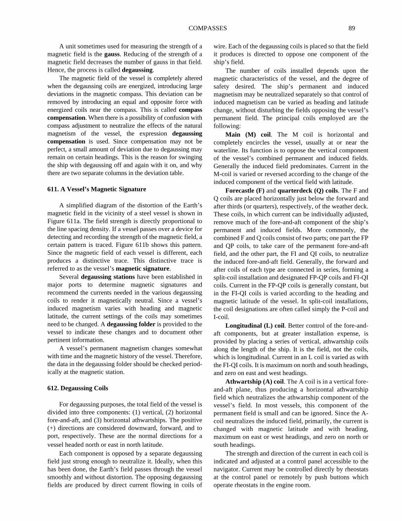
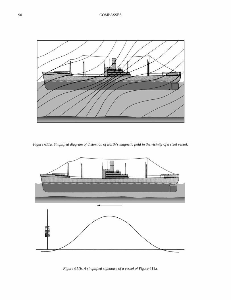
A simplified diagram of the distortion of the Earth’smagnetic field in the vicinity of a steel vessel is shown inFigure 611a. The field strength is directly proportional tothe line spacing density. If a vessel passes over a device fordetecting and recording the strength of the magnetic field, acertain pattern is traced. Figure 611b shows this pattern.Since the magnetic field of each vessel is different, eachproduces a distinctive trace. This distinctive trace isreferred to as the vessel’smagnetic signature.
Severaldegaussing stationshave been established inmajor ports to determine magnetic signatures andrecommend the currents needed in the various degaussingcoils to render it magnetically neutral. Since a vessel’sinduced magnetism varies with heading and magneticlatitude, the current settings of the coils may sometimesneed to be changed. Adegaussing folderis provided to thevessel to indicate these changes and to document otherpertinent information.
A vessel’s permanent magnetism changes somewhatwith time and the magnetic history of the vessel. Therefore,the data in the degaussing folder should be checked period-ically at the magnetic station.
612. Degaussing Coils
For degaussing purposes, the total field of the vessel isdivided into three components: (1) vertical, (2) horizontalfore-and-aft, and (3) horizontal athwartships. The positive(+) directions are considered downward, forward, and toport, respectively. These are the normal directions for avessel headed north or east in north latitude.
Each component is opposed by a separate degaussingfield just strong enough to neutralize it. Ideally, when thishas been done, the Earth’s field passes through the vesselsmoothly and without distortion. The opposing degaussingfields are produced by direct current flowing in coils of
wire. Each of the degaussing coils is placed so that the fieit produces is directed to oppose one component of tship’s field.
The number of coils installed depends upon thmagnetic characteristics of the vessel, and the degreesafety desired. The ship’s permanent and inducmagnetism may be neutralized separately so that controinduced magnetism can be varied as heading and latituchange, without disturbing the fields opposing the vessepermanent field. The principal coils employed are thfollowing:
Main (M) coil . The M coil is horizontal andcompletely encircles the vessel, usually at or near twaterline. Its function is to oppose the vertical componeof the vessel’s combined permanent and induced fieldGenerally the induced field predominates. Current in thM-coil is varied or reversed according to the change of tinduced component of the vertical field with latitude.
Forecastle (F)andquarterdeck (Q) coils. The F andQ coils are placed horizontally just below the forward anafter thirds (or quarters), respectively, of the weather decThese coils, in which current can be individually adjusteremove much of the fore-and-aft component of the shippermanent and induced fields. More commonly, thcombined F and Q coils consist of two parts; one part theand QP coils, to take care of the permanent fore-and-field, and the other part, the FI and QI coils, to neutralizthe induced fore-and-aft field. Generally, the forward anafter coils of each type are connected in series, formingsplit-coil installation and designated FP-QP coils and FI-Qcoils. Current in the FP-QP coils is generally constant, bin the FI-QI coils is varied according to the heading anmagnetic latitude of the vessel. In split-coil installationthe coil designations are often called simply the P-coil aI-coil.
Longitudinal (L) coil . Better control of the fore-and-aft components, but at greater installation expense,provided by placing a series of vertical, athwartship coialong the length of the ship. It is the field, not the coilswhich is longitudinal. Current in an L coil is varied as withthe FI-QI coils. It is maximum on north and south headingand zero on east and west headings.
Athwartship (A) coil . The A coil is in a vertical fore-and-aft plane, thus producing a horizontal athwartshfield which neutralizes the athwartship component of thvessel’s field. In most vessels, this component of thpermanent field is small and can be ignored. Since thecoil neutralizes the induced field, primarily, the current ichanged with magnetic latitude and with headinmaximum on east or west headings, and zero on northsouth headings.
The strength and direction of the current in each coilindicated and adjusted at a control panel accessible tonavigator. Current may be controlled directly by rheostaat the control panel or remotely by push buttons whicoperate rheostats in the engine room.
90 COMPASSES
Figure 611a. Simplified diagram of distortion of Earth’s magnetic field in the vicinity of a steel vessel.
Figure 611b. A simplified signature of a vessel ofFigure 611a.
COMPASSES 91
otndsts
esip.are
isforom
sttic
heing
g
ls
toy
ed
ry
ilslessingllyallll
ard,eer
arirals,dartherlar
n,
Appropriate values of the current in each coil aredetermined at a degaussing station, where the variouscurrents are adjusted until the vessel’s magnetic signature ismade as flat as possible. Recommended current values anddirections for all headings and magnetic latitudes are setforth in the vessel’s degaussing folder. This document isnormally kept by the navigator, who must see that therecommended settings are maintained whenever thedegaussing system is energized.
613. Securing The Degaussing System
Unless the degaussing system is properly secured,residual magnetism may remain in the vessel. Duringdegaussing compensation and at other times, asrecommended in the degaussing folder, the “reversal”method is used. The steps in the reversal process are asfollows:
1. Start with maximum degaussing current used sincethe system was last energized.
2. Decrease current to zero and increase it in theopposite direction to the same value as in step 1.
3. Decrease the current to zero and increase it to three-fourths maximum value in the original direction.
4. Decrease the current to zero and increase it to one-half maximum value in the opposite direction.
5. Decrease the current to zero and increase it to one-fourth maximum value in the original direction.
6. Decrease the current to zero and increase it to one-eighth maximum value in the opposite direction.
7. Decrease the current to zero and open switch.
614. Magnetic Treatment Of Vessels
In some instances, degaussing can be made moreeffective by changing the magnetic characteristics of thevessel by a process known asdeperming. Heavy cables arewound around the vessel in an athwartship direction,forming vertical loops around the longitudinal axis of thevessel. The loops are run beneath the keel, up the sides, andover the top of the weather deck at closely spaced equalintervals along the entire length of the vessel.Predetermined values of direct current are then passedthrough the coils. When the desired magneticcharacteristics have been acquired, the cables are removed.
A vessel which does not have degaussing coils, orwhich has a degaussing system which is inoperative, can begiven some temporary protection by a process known asflashing. A horizontal coil is placed around the outside ofthe vessel and energized with large predetermined values ofdirect current. When the vessel has acquired a vertical fieldof permanent magnetism of the correct magnitude andpolarity to reduce to a minimum the resultant field belowthe vessel for the particular magnetic latitude involved, thecable is removed. This type protection is not as satisfactory
as that provided by degaussing coils because it is nadjustable for various headings and magnetic latitudes, aalso because the vessel’s magnetism slowly readjufollowing treatment.
During magnetic treatment all magnetic compassand Flinders bars should be removed from the shPermanent adjusting magnets and quadrantal correctorsnot materially affected, and need not be removed. If itimpractical to remove a compass, the cables usedmagnetic treatment should be kept as far as practical frit.
615. Degaussing Effects
The degaussing of ships for protection againmagnetic mines creates additional effects upon magnecompasses, which are somewhat different from tpermanent and induced magnetic effects. The degausseffects are electromagnetic, and depend on:
1. Number and type of degaussing coils installed.2. Magnetic strength and polarity of the degaussin
coils.3. Relative location of the different degaussing coi
with respect to the binnacle.4. Presence of masses of steel, which would tend
concentrate or distort magnetic fields in the vicinitof the binnacle.
5. The fact that degaussing coils are operatintermittently, with variable current values, andwith different polarities, as dictated by necessadegaussing conditions.
616. Degaussing Compensation
The magnetic fields created by the degaussing cowould render the vessel’s magnetic compasses useunless compensated. This is accomplished by subjectthe compass to compensating fields along three mutuaperpendicular axes. These fields are provided by smcompensating coilsadjacent to the compass. In nearly ainstallations, one of these coils, theheeling coil, ishorizontal and on the same plane as the compass cproviding a vertical compensating field. Current in thheeling coil is adjusted until the vertical component of thtotal degaussing field is neutralized. The othecompensating coils provide horizontal fields perpendiculto each other. Current is varied in these coils until theresultant field is equal and opposite to the horizontcomponent of the degaussing field. In early installationthese horizontal fields were directed fore-and-aft anathwartships by placing the coils around the Flinders band the quadrantal spheres. Compactness and oadvantages are gained by placing the coils on perpendicuaxes extending 045°-225° and 315°-135° relative to theheading. A frequently used compensating installatio
92 COMPASSES
n,nd
atob-
c-coilthe
en
otthethetalheyebyns,be
d tobyadeby
n.
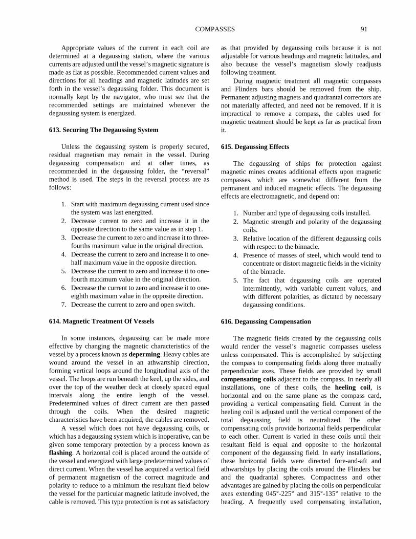
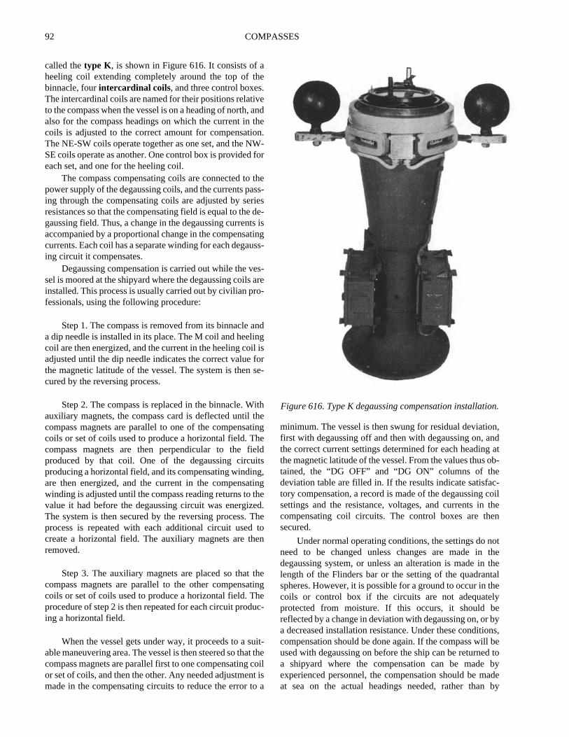
called thetype K, is shown in Figure 616. It consists of aheeling coil extending completely around the top of thebinnacle, fourintercardinal coils, and three control boxes.The intercardinal coils are named for their positions relativeto the compass when the vessel is on a heading of north, andalso for the compass headings on which the current in thecoils is adjusted to the correct amount for compensation.The NE-SW coils operate together as one set, and the NW-SE coils operate as another. One control box is provided foreach set, and one for the heeling coil.
The compass compensating coils are connected to thepower supply of the degaussing coils, and the currents pass-ing through the compensating coils are adjusted by seriesresistances so that the compensating field is equal to the de-gaussing field. Thus, a change in the degaussing currents isaccompanied by a proportional change in the compensatingcurrents. Each coil has a separate winding for each degauss-ing circuit it compensates.
Degaussing compensation is carried out while the ves-sel is moored at the shipyard where the degaussing coils areinstalled. This process is usually carried out by civilian pro-fessionals, using the following procedure:
Step 1. The compass is removed from its binnacle anda dip needle is installed in its place. The M coil and heelingcoil are then energized, and the current in the heeling coil isadjusted until the dip needle indicates the correct value forthe magnetic latitude of the vessel. The system is then se-cured by the reversing process.
Step 2. The compass is replaced in the binnacle. Withauxiliary magnets, the compass card is deflected until thecompass magnets are parallel to one of the compensatingcoils or set of coils used to produce a horizontal field. Thecompass magnets are then perpendicular to the fieldproduced by that coil. One of the degaussing circuitsproducing a horizontal field, and its compensating winding,are then energized, and the current in the compensatingwinding is adjusted until the compass reading returns to thevalue it had before the degaussing circuit was energized.The system is then secured by the reversing process. Theprocess is repeated with each additional circuit used tocreate a horizontal field. The auxiliary magnets are thenremoved.
Step 3. The auxiliary magnets are placed so that thecompass magnets are parallel to the other compensatingcoils or set of coils used to produce a horizontal field. Theprocedure of step 2 is then repeated for each circuit produc-ing a horizontal field.
When the vessel gets under way, it proceeds to a suit-able maneuvering area. The vessel is then steered so that thecompass magnets are parallel first to one compensating coilor set of coils, and then the other. Any needed adjustment ismade in the compensating circuits to reduce the error to a
minimum. The vessel is then swung for residual deviatiofirst with degaussing off and then with degaussing on, athe correct current settings determined for each headingthe magnetic latitude of the vessel. From the values thustained, the “DG OFF” and “DG ON” columns of thedeviation table are filled in. If the results indicate satisfatory compensation, a record is made of the degaussingsettings and the resistance, voltages, and currents incompensating coil circuits. The control boxes are thsecured.
Under normal operating conditions, the settings do nneed to be changed unless changes are made indegaussing system, or unless an alteration is made inlength of the Flinders bar or the setting of the quadranspheres. However, it is possible for a ground to occur in tcoils or control box if the circuits are not adequatelprotected from moisture. If this occurs, it should breflected by a change in deviation with degaussing on, ora decreased installation resistance. Under these conditiocompensation should be done again. If the compass willused with degaussing on before the ship can be returnea shipyard where the compensation can be madeexperienced personnel, the compensation should be mat sea on the actual headings needed, rather than
Figure 616. Type K degaussing compensation installatio
COMPASSES 93
iconforgss
theaintis
eekal
ek
theee
n
irsollyityontak-ofofd,i-eadg
e
og
inly
ed
r.r
snaste
herly
deflection of the compass needles by magnets. Morecomplete information related to this process is given in thedegaussing folder.
If a vessel has been given magnetic treatment, itsmagnetic properties have changed, necessitatingreadjustment of each magnetic compass. This is best
delayed for several days to permit the magnetcharacteristics of the vessel to settle. If compensaticannot be delayed, the vessel should be swung againresidual deviation after a few days. Degaussincompensation should not be made until after compaadjustment has been completed.
GYROCOMPASSES
617. Principles of the Gyroscope
A gyroscope consists of a spinning wheel or rotorcontained within gimbals which permit movement aboutthree mutually perpendicular axes, known as thehorizontal axis, thevertical axis, and thespin axis. Whenspun rapidly, assuming that friction is not considered, thegyroscope developsgyroscopic inertia, tending to remainspinning in the same plane indefinitely. The amount ofgyroscopic inertia depends on the angular velocity, mass,and radius of the wheel or rotor.
When a force is applied to change alignment of the spinaxis of a gyroscope, the resultant motion is perpendicular tothe direction of the force. This tendency is known asprecession. A force applied to the center of gravity of thegyroscope will move the entire system in the direction ofthe force. Only a force that tends to change the axis ofrotation produces precession.
If a gyroscope is placed at the equator with its spin axispointing east-west, as the earth turns on its axis, gyroscopicinertia will tend to keep the plane of rotation constant. Tothe observer, it is the gyroscope which is seen to rotate, notthe earth. This effect is called the horizontal earth rate, andis maximum at the equator and zero at the poles. At pointsbetween, it is equal to the cosine of the latitude.
If the gyro is placed at a geographic pole with its spinaxis horizontal, it will appear to rotate about its verticalaxis. This is the vertical earth rate. At all points between theequator and the poles, the gyro appears to turn partly aboutits horizontal and partly about its vertical axis, beingaffected by both horizontal and vertical earth rates. In orderto visualize these effects, remember that the gyro, atwhatever latitude it is placed, is remaining aligned in spacewhile the earth moves beneath it.
618. Gyrocompass Operation
The gyrocompass depends upon four naturalphenomena: gyroscopic inertia, precession, earth’srotation, and gravity. To make a gyroscope into agyrocompass, the wheel or rotor is mounted in a sphere,called the gyrosphere, and the sphere is then supported in avertical ring. The whole is mounted on a base called thephantom. The gyroscope in a gyrocompass can bependulous or non-pendulous, according to design. The rotormay weigh as little as half a kilogram to over 25 kg.
To make it seek and maintain true north, three things
are necessary. First, the gyro must be made to stay onplane of the meridian. Second, it must be made to remhorizontal. Third, it must stay in this position once ireaches it regardless of what the vessel on which itmounted does or where it goes on the earth. To make it sthe meridian, a weight is added to the bottom of the verticring, causing it to swing on its vertical axis, and thus seto align itself horizontally. It will tend to oscillate, so asecond weight is added to the side of the sphere in whichrotor is contained, which dampens the oscillations until thgyro stays on the meridian. With these two weights, thonly possible position of equilibrium is on the meridiawith its spin axis horizontal.
To make the gyro seek north, a system of reservofilled with mercury, known as mercury ballistics, is used tapply a force against the spin axis. The ballistics, usuafour in number, are placed so that their centers of gravexactly coincide with the CG of the gyroscope. Precessithen causes the spin axis to trace an ellipse, one ellipseing about 84 minutes to complete. (This is the periodoscillation of a pendulum with an arm equal to the radiusthe earth.) To dampen this oscillation, the force is applienot in the vertical plane, but slightly to the east of the vertcal plane. This causes the spin axis to trace a spiral instof an ellipse and eventually settle on the meridian pointinnorth.
619. Gyrocompass Errors
The total of the all the combined errors of thgyrocompass is calledgyro error and is expressed indegrees E or W, just like variation and deviation. But gyrerror, unlike magnetic compass error, and beinindependent of Earth’s magnetic field, will be constantone direction; that is, an error of one degree east will appto all bearings all around the compass.
The errors to which a gyrocompass is subject are speerror, latitude error, ballistic deflection error, ballisticdamping error, quadrantal error, and gimballing erroAdditional errors may be introduced by a malfunction oincorrect alignment with the centerline of the vessel.
Speed error is caused by the fact that a gyrocompasonly moves directly east or west when it is stationary (othe rotating earth) or placed on a vessel moving exactly eor west. Any movement to the north or south will cause thcompass to trace a path which is actually a function of tspeed of advance and the amount of northerly or southe
94 COMPASSES
hs,site
e.Tohd-e
m,
beingt aical
caltlean
an
heismsels
esdesct
ashen.thegsy
d toireuldare
forees,ct
heading. This causes the compass to tend to settle a bit offtrue north. This error is westerly if the vessel’s course isnortherly, and easterly if the course is southerly. Itsmagnitude depends on the vessel’s speed, course, andlatitude. This error can be corrected internally by means ofa cosine cam mounted on the underside of the azimuth gear,which removes most of the error. Any remaining error isminor in amount and can be disregarded.
Tangent latitude error is a property only of gyroswith mercury ballistics, and is easterly in north latitudesand westerly in south latitudes. This error is also correctedinternally, by offsetting the lubber’s line or with a smallmovable weight attached to the casing.
Ballistic deflection error occurs when there is amarked change in the north-south component of the speed.East-west accelerations have no effect. A change of courseor speed also results in speed error in the opposite direction,and the two tend to cancel each other if the compass isproperly designed. This aspect of design involves slightlyoffsetting the ballistics according to the operating latitude,upon which the correction is dependent. As latitudechanges, the error becomes apparent, but can be minimizedby adjusting the offset.
Ballistic damping error is a temporary oscillationintroduced by changes in course or speed. During a changein course or speed, the mercury in the ballistic is subjectedto centrifugal and acceleration/deceleration forces. Thiscauses a torquing of the spin axis and subsequent error inthe compass reading. Slow changes do not introduceenough error to be a problem, but rapid changes will. Thiserror is counteracted by changing the position of theballistics so that the true vertical axis is centered, thus notsubject to error, but only when certain rates of turn oracceleration are exceeded.
Quadrantal error has two causes. The first occurs ifthe center of gravity of the gyro is not exactly centered inthe phantom. This causes the gyro to tend to swing along itsheavy axis as the vessel rolls in the sea. It is minimized byadding weight so that the mass is the same in all directionsfrom the center. Without a long axis of weight, there is notendency to swing in one particular direction. The secondsource of quadrantal error is more difficult to eliminate. Asa vessel rolls in the sea, the apparent vertical axis isdisplaced, first to one side and then the other. The verticalaxis of the gyro tends to align itself with the apparentvertical. On northerly or southerly courses, and on easterlyor westerly courses, the compass precesses equally to bothsides and the resulting error is zero. On intercardinalcourses, the N-S and E-W precessions are additive, and apersistent error is introduced, which changes direction indifferent quadrants. This error is corrected by use of a
second gyroscope called a floating ballistic, whicstabilizes the mercury ballistic as the vessel rolleliminating the error. Another method is to use two gyrofor the directive element, which tend to precess in opposdirections, neutralizing the error.
Gimballing error is caused by taking readings fromthe compass card when it is tilted from the horizontal planIt applies to the compass itself and to all repeaters.minimize this error, the outer ring of the gimbal of eacrepeater should be installed in alignment with the fore-anaft line of the vessel. Of course, the lubber’s line must bexactly centered as well.
620. Using the Gyrocompass
Since a gyrocompass is not influenced by magnetisit is not subject to variation or deviation. Any error isconstant and equal around the horizon, and can oftenreduced to less than one degree, thus effectively eliminatit altogether. Unlike a magnetic compass, it can outpusignal to repeaters spaced around the vessel at critpositions.
But it also requires a constant source of stable electripower, and if power is lost, it requires several hours to seton the meridian again before it can be used. This period cbe reduced by aligning the compass with the meridibefore turning on the power.
The directive force of a gyrocompass depends on tamount of precession to which it is subject, which in turndependent on latitude. Thus the directive force is maximuat the equator and decreases to zero at the poles. Vesoperating in high latitudes must construct error curvbased on latitudes because the errors at high latitueventually overcome the ability of the compass to correthem.
The gyrocompass is typically located below decksclose as possible to the center of roll, pitch and yaw of tship, thus minimizing errors caused by the ship’s motioRepeaters are located at convenient places throughoutship, such as at the helm for steering, on the bridge winfor taking bearings, in after steering for emergencsteering, and other places. The output can also be usedrive course recorders, autopilot systems, plotters, fcontrol systems, and stabilized radars. The repeaters shobe checked regularly against the master to ensure theyall in alignment. The repeaters on the bridge wing usedtaking bearings will likely be equipped with removablbearing circles, azimuth circles, and telescopic alidadwhich allow one to sight a distant object and see its exagyrocompass bearing.
COMPASSES 95
icry,letic
alte.d
dre
these-ldales,es,
isheat’sof
teddts,
els.e
chblet,e.atn.n.
ofroedissnwsnhend
isy
ione.ly
he
rsill
ELECTRONIC COMPASSES
621. New Direction Sensing Technologies
The magnetic compass has serious limitations, chieflythat of being unable to isolate the earth’s magnetic fieldfrom all others close enough to influence it. It also indicatesmagnetic north, whereas the mariner is most interested intrue north. Most of the work involved with compensating atraditional magnetic compass involves neutralizingmagnetic influences other than the earth’s, a complicatedand inexact process often involving more art than science.Residual error is almost always present even aftercompensation. Degaussing complicates the situationimmensely.
The electro-mechanical gyrocompass has been thestandard steering and navigational compass since the early20th century, and has provided several generations ofmariners a stable and reliable heading and bearingreference. However, it too has limitations: It is a large,expensive, heavy, sensitive device that must be mountedaccording to rather strict limitations. It requires a stable anduninterrupted supply of electrical power; it is sensitive toshock, vibration, and environmental changes; and it needsseveral hours to settle after being turned on.
Fortunately, several new technologies have beendeveloped which promise to greatly reduce or eliminate thelimitations of both the mechanical gyroscope andtraditional magnetic compasses. Sometimes referred to as“electronic compasses,” the digital flux gate magneticcompass and the ring laser gyrocompass are two suchdevices. They have the following advantages:
1. Solid state electronics, no moving parts2. Operation at very low power3. Easy backup power from independent sources4. Standardized digital output5. Zero friction, drift, or wear6. Compact, lightweight, and inexpensive7. Rapid start-up and self-alignment8. Low sensitivity to vibration, shock, and
temperature changes9. Self-correcting
Both types are being installed on many vessels as theprimary directional reference, enabling thedecommissioning of the traditional magnetic compassesand the avoidance of periodic compensation andmaintenance.
622. The Flux Gate Compass
The most widely used sensor for digital compasses isthe flux-gate magnetometer, developed around 1928.Initially it was used for detecting submarines, forgeophysical prospecting, and airborne mapping of earth’s
magnetic fields.The most common type, called the second harmon
device, incorporates two coils, a primary and a secondaboth wrapped around a single highly permeabferromagnetic core. In the presence of an external magnefield, the core’s magnetic induction changes. A signapplied to the primary winding causes the core to oscillaThe secondary winding emits a signal that is inducethrough the core from the primary winding. This inducesignal is affected by changes in the permeability of the coand appears as an amplitude variation in the output ofsensing coil. The signal is then demodulated with a phasensitive detector and filtered to retrieve the magnetic fievalue. After being converted to a standardized digitformat, the data can be output to numerous remote devicincluding steering compasses, bearing compassemergency steering stations, and autopilots.
Since the influence of a ship’s inherent magnetisminversely proportional to the square of the distance to tcompass, it is logical that if the compass could be locatedsome distance from the ship, the influence of the shipmagnetic field could be greatly reduced. One advantagethe flux gate compass is that the sensor can be locaremotely from the readout device, allowing it to be placeat a position as far as possible from the hull and its contensuch as high up on a mast, the ideal place on most vess
A further advantage is that the digital signal can bprocessed mathematically, and algorithms written whican correct for observed deviation once the deviation tahas been determined. Further, the “table,” in digital formacan be found by merely steering the vessel in a full circlAlgorithms then determine and apply corrections theffectively flatten the usual sine wave pattern of deviatioThe theoretical result is zero observed compass deviatio
Should there be an index error (which has the effectskewing the entire sine wave below or above the zedegree axis of the deviation curve) this can be correctwith an index correction applied to all the readings. Thproblem is largely confined to asymmetric installationsuch as aircraft carriers. Similarly, a correction for variatiocan be applied, and with GPS input (so the system knowhere it is with respect to the isogonic map) the variatiocorrection can be applied automatically, thus rendering toutput in true degrees, corrected for both deviation avariation.
It is important to remember that a flux gate compassstill a magnetic compass, and that it will be influenced blarge changes to the ship’s magnetic field. Compensatshould be accomplished after every such changFortunately, as noted, compensation involves meresteering the vessel in a circle in accordance with tmanufacturer’s recommendations.
Flux-gate compasses from different manufactureshare some similar operational modes. Most of them w
96 COMPASSES
ad
en
illof
fulhtorssea
elederics
yd aoheene ofmsills,edeatheut
to aas
aa
ssese
act,he
icshe
blerosingfonionceshersand
have the following:
SET COURSE MODE: A course can be set and“remembered” by the system, which then provides thehelmsman a graphic steering aid, enabling him to see if theship’s head is right or left of the set course, as if on a digital“highway.” Normal compass operation continues in thebackground.
DISPLAY RESPONSE DAMPING: In this mode, aswitch is used to change the rate of damping and update ofthe display in response to changes in sea condition andvessel speed.
AUTO-COMPENSATION: This mode is used todetermine the deviation curve for the vessel as it steams ina complete circle. The system will then automaticallycompute correction factors to apply around the entirecompass, resulting in zero deviation at any given heading.This should be done after every significant change in themagnetic signature of the ship, and within 24 hours ofentering restricted waters.
CONTINUOUS AUTO-COMPENSATION: Thismode, which should normally be turned OFF in restrictedwaters and ON at sea, runs the compensation algorithmeach time the ship completes a 360 degree turn in twominutes. A warning will flash on the display in the OFFmode.
PRE-SET VARIATION: In effect an index correction,pre-set variation allows the application of magneticvariation to the heading, resulting in a true output(assuming the unit has been properly compensated andaligned). Since variation changes according to one’slocation on the earth, it must be changed periodically toagree with the charted variation unless GPS input isprovided. The GPS position input is used in an algorithmwhich computes the variation for the area and automaticallycorrects the readout.
U.S. Naval policy approves the use of flux gatecompasses and the decommissioning, but not removal, ofthe traditional binnacle mounted compass, which should beclearly marked as “Out of Commission” once an approvedflux gate compass is properly installed and tested.
623. The Ring Laser Gyrocompass
The ring laser had its beginnings in England, where inthe 1890’s two scientists, Joseph Larmor and Sir OliverLodge (also one of the pioneers of radio), debated thepossibility of measuring rotation by a ring interferometer.Some 15 years later, a French physicist, Georges Sagnac,fully described the phenomenon which today bears hisname, the Sagnac Effect. This principle states that if two
beams of light are sent in opposite directions around“ring” or polyhedron and steered so as to meet ancombine, a standing wave will form around the ring. If thwave is observed from any point, and that point is themoved along the perimeter of the ring, the wave form wchange in direct relationship to the direction and velocitymovement.
It wasn’t until 1963 that W. Macek of Sperry-RandCorporation tested and refined the concept into a useresearch device. Initially, mirrors were used to direct ligaround a square or rectangular pattern. But such mirrmust be made and adjusted to exceptionally clotolerances to allow useful output, and must operate invacuum for best effect. Multilayer dielectric mirrors with areflectivity of 99.9999 percent were developed. Thinvention of laser light sources and fiber-optics has enabthe production of small, light, and dependable ring lasgyros. Mirror-based devices continue to be used in physresearch.
The ring laser gyrocompass (RLG) operates bmeasuring laser-generated light waves traveling arounfiber-optic ring. A beam splitter divides a beam of light inttwo counter-rotating waves, which then travel around tfiber-optic ring in opposite directions. The beams are threcombined and sent to an output detector. In the absencrotation, the path lengths will be the same and the beawill recombine in phase. If the device has rotated, there wbe a difference in the length of the paths of the two beamresulting in a detectable phase difference in the combinsignal. The signal will vary in amplitude depending on thamount of the phase shift. The amplitude is thusmeasurement of the phase shift, and consequently,rotation rate. This signal is processed into a digital readoin degrees. This readout, being digital, can then be sentvariety of devices which need heading information, suchhelm, autopilot, and electronic chart systems.
A single ring laser gyroscope can be used to provideone-dimensional rotational reference, exactly whatcompass needs. The usefulness of ring laser gyrocompastems from that fact that they share many of the samcharacteristics of flux gate compasses. They are complight, inexpensive, accurate, dependable, and robust. Tring laser device is also quite immune to magnetinfluences which would send a traditional compasspinning hopelessly, and might adversely affect even tremotely mounted flux gate compass.
Ring laser gyroscopes can also serve as the staelements in an inertial guidance system, using three gyto represent the three degrees of freedom, thus providboth directional and position information. The principle ooperation is the same as for mechanical inertial navigatidevices, in that a single gyro can measure any rotatabout its own axis. This implies that its orientation in spaabout its own axis will be known at all times. Three gyroarranged along three axes each at 90 degrees to the otcan measure accelerations in three dimensional space,
COMPASSES 97
s,of
c
e
est.ct
dd
tss,nerlyns
sse
s.ss.
y.
thus track movement over time.Inertial navigation systems based on ring lasers have
been used in aircraft for a number of years, and arebecoming increasingly common in maritime applications.
Uses include navigation, radar and fire control systemprecise weapons stabilization, and stabilizationdirectional sensors such as satellite antennas.
CORRECTING AND UNCORRECTING THE COMPASS
624. Ship’s Heading
Ship’s heading is the angle, expressed in degreesclockwise from north, of the ship’s fore-and-aft line withrespect to the true meridian or the magnetic meridian. Whenthis angle is referred to the true meridian, it is called atrueheading. When this angle is referred to the magneticmeridian, it is called amagnetic heading. Heading, asindicated on a particular compass, is termed the ship’scompass heading by that compass. It is essential to specifyevery heading as true (T), magnetic (M), or compass. Twoabbreviations simplify recording of compass directions.The abbreviation PGC refers to “per gyro compass,” andPSC refers to “per steering compass.” The steering compassis the one being used by the helmsman or autopilot,regardless of type.
625. Variation And Deviation
Variation is the angle between the magnetic meridianand the true meridian at a given location. If the northerlypart of the magnetic meridian lies to the right of the truemeridian, the variation is easterly. Conversely, if this part isto the left of the true meridian, the variation is westerly. Thelocal variation and its smallannual changeare noted on thecompass rose of all navigational charts. Thus the true andmagnetic headings of a ship differ by the local variation.
As previously explained, a ship’s magnetic influencewill generally cause the compass needle to deflect from themagnetic meridian. This angle of deflection is calleddeviation. If the north end of the needle points east of themagnetic meridian, the deviation is easterly; if it pointswest of the magnetic meridian, the deviation is westerly.
626. Heading Relationships
A summary of heading relationships follows:
1. Deviation is the difference between the compassheading and the magnetic heading.
2. Variation is the difference between the magnetiheading and the true heading.
3. The algebraic sum of deviation and variation is thcompass error.
The following simple rules will assist in correcting anduncorrecting the compass:
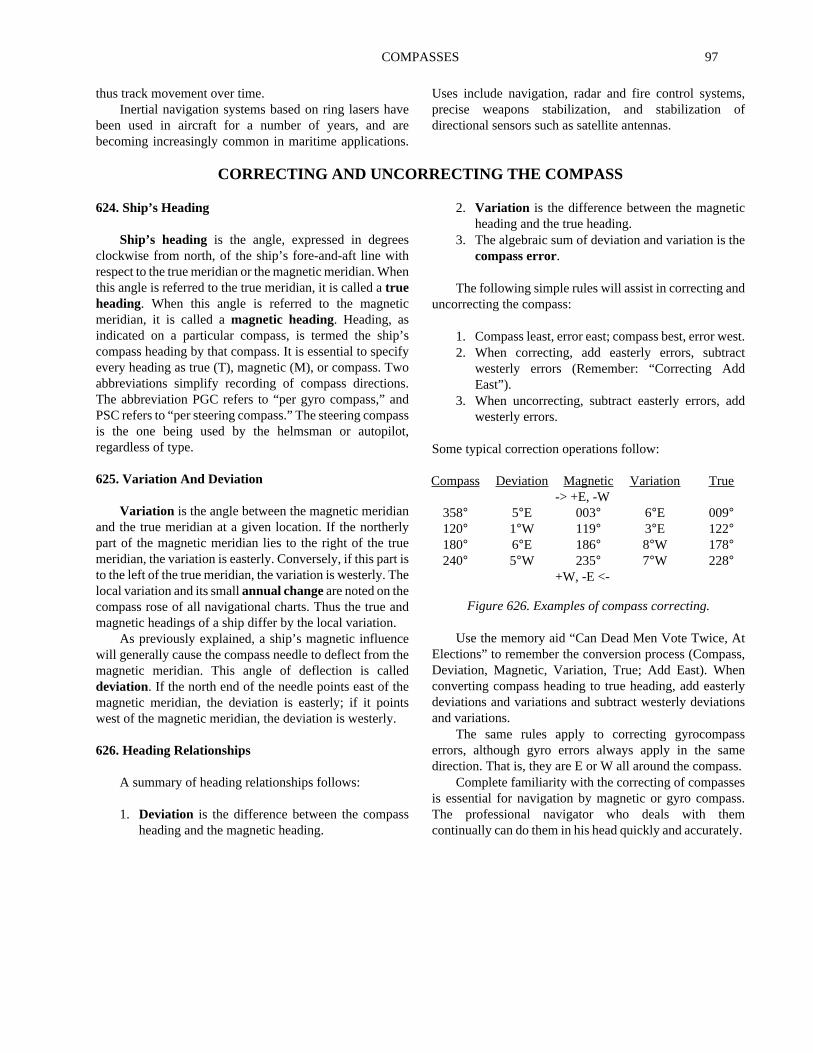
1. Compass least, error east; compass best, error w2. When correcting, add easterly errors, subtra
westerly errors (Remember: “Correcting AddEast”).
3. When uncorrecting, subtract easterly errors, awesterly errors.
Some typical correction operations follow:
Use the memory aid “Can Dead Men Vote Twice, AElections” to remember the conversion process (CompaDeviation, Magnetic, Variation, True; Add East). Wheconverting compass heading to true heading, add eastdeviations and variations and subtract westerly deviatioand variations.
The same rules apply to correcting gyrocompaerrors, although gyro errors always apply in the samdirection. That is, they are E or W all around the compas
Complete familiarity with the correcting of compasseis essential for navigation by magnetic or gyro compasThe professional navigator who deals with themcontinually can do them in his head quickly and accuratel
Compass Deviation Magnetic Variation True-> +E, -W
358° 5°E 003° 6°E 009°120° 1°W 119° 3°E 122°180° 6°E 186° 8°W 178°240° 5°W 235° 7°W 228°
+W, -E <-
Figure 626. Examples of compass correcting.