
CHAPTER 6 A CASE STUDY OF SHOCK ABSORBER...
39
80 CHAPTER 6 A CASE STUDY OF SHOCK ABSORBER PRODUCTION PLANT In this chapter presented a case study of CONKAN model implementation in Shock Absorber Production plant GIL, India. Gabriel India Limited, Dewas. That is situated 6 Kms, from Dewas city. Gabriel is the primary ride control band of Arvin Meritor light vehicle aftermarket. Since 1970, when Gabriel introduced the first shock absorber in America, Gabriel is a leader in innovating ride control product for the market place. 6.1 Shock Absorber Shock absorber is an essential part of an automobile for absorbing shock during the movement of the automobile. Shock absorber or shox as they are popularly known, function as dampers of shock resulting from vertical vibration of vehicle. Their basic function to absorb shocks, which are transmitted from the wheels to frame. Thus, they ensure comfortable ride and a better control on vehicle being driven. In addition, they also enhance the life of the vehicle in general and other component in particular. Shock absorber is used in most automobiles like two or three wheelers, cars, jeeps, tractors and Light motor vehicles. Heavy commercial vehicles do not use shock absorbers. They use parabolic spring which can take higher loads. The product mix for shock absorber industry can be defined in various head such as by type – dampers/struts/forks or by special user like defense/railways etc. Major shock absorbers manufacturing in India are as M/s Escorts, Gabriel, Hydraulics, Munjal Showa, Super Shock Sirmour Sudburg, Knorr Bremse etc. In India over 22 millions of shock absorbers are manufactured. The demand for various segment of shock absorbers in volume are over 65% for 2/3 wheelers, 28.95% for cars and Jeeps and around 6% for LCVs. Also out of the total demand, about 55% are used by OEMs, 10% for exports and less then 35% for replacements. Like other auto ancillaries, shock absorbers are highly technology intensive. Various India shock absorber manufacturers have collaboration with foreign companies.
Transcript of CHAPTER 6 A CASE STUDY OF SHOCK ABSORBER...

80
CHAPTER 6
A CASE STUDY OF SHOCK ABSORBER PRODUCTION PLANT
In this chapter presented a case study of CONKAN model implementation in
Shock Absorber Production plant GIL, India. Gabriel India Limited, Dewas. That is
situated 6 Kms, from Dewas city. Gabriel is the primary ride control band of Arvin
Meritor light vehicle aftermarket. Since 1970, when Gabriel introduced the first shock
absorber in America, Gabriel is a leader in innovating ride control product for the market
place.
6.1 Shock Absorber
Shock absorber is an essential part of an automobile for absorbing shock during
the movement of the automobile. Shock absorber or shox as they are popularly known,
function as dampers of shock resulting from vertical vibration of vehicle. Their basic
function to absorb shocks, which are transmitted from the wheels to frame. Thus, they
ensure comfortable ride and a better control on vehicle being driven. In addition, they
also enhance the life of the vehicle in general and other component in particular.
Shock absorber is used in most automobiles like two or three wheelers, cars,
jeeps, tractors and Light motor vehicles. Heavy commercial vehicles do not use shock
absorbers. They use parabolic spring which can take higher loads. The product mix for
shock absorber industry can be defined in various head such as by type –
dampers/struts/forks or by special user like defense/railways etc. Major shock absorbers
manufacturing in India are as M/s Escorts, Gabriel, Hydraulics, Munjal Showa, Super
Shock Sirmour Sudburg, Knorr Bremse etc. In India over 22 millions of shock absorbers
are manufactured. The demand for various segment of shock absorbers in volume are
over 65% for 2/3 wheelers, 28.95% for cars and Jeeps and around 6% for LCVs. Also out
of the total demand, about 55% are used by OEMs, 10% for exports and less then 35%
for replacements.
Like other auto ancillaries, shock absorbers are highly technology intensive. Various
India shock absorber manufacturers have collaboration with foreign companies.

81
Types of Shock Absorber
The shock absorbers are of many types. It may by operating on friction,
compressed air and hydraulically. Of these, the hydraulic type shock absorber is
commonly used several designs of hydraulic shock absorber have been used such as
direct acting, parallel cylinder shock absorbers are called hydraulic dampers because they
hydraulically dump extra movements on the wheels. The vane type shock absorber has
vanes that rotate in the cylindrical chamber filled with fluid. The direct acting shock
absorber are mostly widely used and it consist of three concentric tubes ie. Cylinder tube,
reservoir tube and dust tube and a piston together with valves, seals gaskets etc.
In the case of mopeds and motorcycles, the front wheel has fork fronts in lieu of
shock absorber. Functionally both of them are used for the same purpose but since
technology differs in the manufacture of each, they are classified as forks and shox
respectively. However in India most of the shock absorber manufacturers fork fronts.
As strut is suspension link between the chassis of a car and wheel assembly. It
comprises of coil spring and shock absorber. Being a load bearing member, it basically
acts as safety item last longer and cost more than shock absorber as it can withstand a
higher load it is basically used in passengers cars, jeeps, and LCVs.
Working of Shock Absorber
Shock absorber work on the principle of ‘Compression/Expansion of cylinder and
piston to provide comfortable ride.’ As the shock absorber moves on the odd/even
surface, it will shorten or elongate and compress filled fluid ie shock absorber oil. When
shock absorber shortens, piston rod forces the piston down into the cylinder tube, thereby
putting the fluid below the piston. At the same time, it creates vacuum in the cylinder
tube above the piston. The fluid is forced through small orifice, or opening in the piston,
and into upper part of the cylinder tube. On the rebound when the wheel moves
downwards after passing into a hole or bumb road, shock absorbers extended. As this
happens the piston moves into upper part of the cylinder tube, thereby forcing fluid from
upper into lower part of the tube.

82
Functions of Shock Absorber
A shock absorber is a device that resists motion. Because it does that, it is used in
a wide variety of applications to stop unwanted motion to provide safe control of a
necessary motion to provide a measured response to a given energy input.
The most common application of shock absorber is in a vehicle suspension, where
pumps in the road start a bouncing motion in the wheels (unsprung mass) and the body
(sprung mass). While the suspension motion required to negotiate the bump is allowed by
the springs subsequent oscillation of the wheels and body are unwanted. Therefore, a
shock absorber is connected between the axle and the body to minimize the extra body
bounces or wheel hops. In this application it is often called a spring damager.
There are sizes for any suspension from gold carts to heavy duty trucks. Trucks
cab suspension and seat suspension are called upon to provide further isolation for the
driver from road (or off-road) bumps and these, too use shock absorbers to damp out
unwanted extra oscillations. Steering inputs from the driver to the road wheels are
necessary to control the direction that a vehicle will move, but sudden impacts from the
road feeding back to the steering wheel can tire the driver and jeopardize the safe
progress of the vehicle. A shock absorber, called a steering damper, connected between
the frame and the steering linkage, can permit the necessary slow steering motion with
little extra effort and yet respond strongly to control sudden feedback from the road
thereby helping to keep the vehicle safely on course. When a spring loaded device is
unlatched it may tend to pop into a new position very rapidly, like a jack-in-the-box. A
shock absorber is sensitive to stroking speed and this makes it useful in exercise slowly
with only a slight effort, but as the tempo increase so the shock absorb resistance increase
providing a measured response to the energy input.
A shock absorber is in fact an energy absorber because it absorb the excess energy
in system to stop the motion or control the action. This energy show up as heat in the
shock absorber, causing its temperature to rise until heat dissipates into the atmosphere.
6.2 Description of Existing Production System
After buffing piston rods are 100% inspected for surface defects i.e. free from
dents, scratch marks, grinding marks, material defects. The inspection is carried out

83
visually. Surface roughness is also inspected once/shift on surface tester (0.08 to 0.2
microns)
After inspection, piston rods are sent for assembling the shocks in various cells.
For assembling the shocks, there are three cells in Gabriel –
a. B Cell
b. NB Cell
c. E Cell
6.2.1 Major Manufacturing Process
1. Stage Washing Machine
As it is named so, the washing of inter, inner tube, eyering is done in 4 stages.
This washing is done to clean the items to remove grease and dust, as they are directly
coming from different vendors.
1st Stage – Washing is done with the help of chemicals, which is the solution of water and
Pyroclean 499 or GTZ. They are heated by steam coming from diesel boiler. Temperature
maintained is 60-750C
2nd
Stage – Same as the 1st Stage
3rd
Stage – To remove any marks of chemical treatment, the input material is washed with
pure hot water temperature maintained in this stage is 60-750C
4th
Stage – To make the inputs dry, so that it won’t rust, it is treated with hot air. Expect
the 4th
stage, every stage got 36 nozzles for spraying fumes at input materials.
2. Sizing And Flaring
Sizing primarily ensures dimensional accuracy without increasing density or
strength. Sizing is done for accurate fixing of housing and seam welding. Flaring is done
for easy fitting of piston assembly. Device used in Gabriel is a pneumatically controlled
where upper punch does flaring and lower punch does sizing. According to product series
diameters, we have different punches. Sizing and flaring operation is done on inter and
dust tube pressure applied is 4.0 to 5.0 Kg/Cm2
3. Hydraulic Ball Burnishing Machine
Burnishing is a cold working operation which simply compress metal through
plastic deformation into smooth, hard surfaces free of objectionable irregularities. This

84
action also tend to improve the physical property of the surface by compressing its grain
structure, thereby increasing its tensile strength. Burnishing does not remove the metal.
In Gabriel, burnishing carried out is hydraulic ball burnishing. It is carried out for
straightening the inner tube, in which piston can move easily without objectionable
irregularities. It consist of a hydraulic cylinder which can generate pressure upto 25 bar.
The motion of hydraulic assembly is transferred to quick change pusher rods which
pusher the standard ball into the hollow tube for burnishing. Burnishing machine frame is
also provided with guide rods, whose function is to guide the motion of pusher rod, else it
may not move straight. Also we have V-block with square magnet to hold inner tube acts
as further and inductive proximity switches which controls the lengths or motion of
pusher rod.
4. Ultrasonic Washing Machine
Ultrasonic washing is a process of removing material by the action of abrasive
particles vibrating in a liquid slurry which circulates through a narrow gap b/w the work
piece and a tool. It is used for washing in a tube and piston head, thus, removing
unwanted material so that the movement of piston head in a inner tube is smooth.
Chemical used for washing Trichloro Ethylene, machine used in Gabriel has a capacity 6
buckets, each buckets has a capacity of 45 tubes. At a time, 3 buckets can be washed.
Motion of buckets is through chain drive.
5. Piston Swedging
Piston Swedging is hydraulically operated through which piston head is
assembled with recoil spring by applying the pressure of 100 – 120 Kg/Cm2
1. Protector : It distributes the damping force equally on piston head
2. O- ring / Piston ring : According to the product specification we can have any
one of them. It prevents leakage.
3. Carrier : Carrier protector and O-ring. It also carries the slot for the fluid flow.
4. Valve spring : It helps in flow of fluid during compression.
6. Marking Machine

85
Through hydraulic press, inter tube marking is done. Product no., licence no.,
trade mark etc. are marked on inter tube. System pressure for hydraulic press is 40-50
Kg/Cm2
7. Inter Seam Welding
Resistance welding produces a series of overlapping spot welds on work pieces.
The work is gripped b/w two narrow wheels that serve as electrodes. The current passes
and flow is interrupted to form a distinct line of weld nuggets. Wheel rotational speed,
pressure and current flow are carefully regulated to produce the desired weld pattern.
Seam welds generally overlap to create a water or airtight joint. Through this process,
inter tube cap is welded with inter tube.
8. Lower Mounting Projection Welding
Resistance projection welding employs special spot welds in which the placement
of the weld nuggets is controlled by projection on one or both of the work pieces. The
parts to be welded are held under pressure b/w electrodes, but contact each other only at
projections. The metals of area of contact are melted to form the weld nuggets. This
welding enables two or more spot welds to be made at the same time with one pair of
electrodes. In this plant, according to product specification, either stud or eyering is
welded on the inter tube cap.
9. Lower Mounting Arc Welding
To provide additional strength and toughness to the joint made by projection
welding metal inert gas welding is carried out. This employs the heat of an electric arc
b/w the work piece and a consumable electrodes that supplies the filler metal. It is type of
gas shielded arc welding and consequently no flux or coating is used on the filler
material. Welding take place in an atmosphere of gas that shields the metal from the air.
Gas used here is Co2
Flow rate with Co2 – 10 – 14 LPM
Wire feed rate – 3.0 – 4.0 M/Min
Current – 180 – 260 Amp
Voltage – 22 – 30 Volts

86
10. Inter Tube Leak Testing
During the operation, inter tube is filled with air, while it is submerged in water,
hence this process shows presence of any holes or cracks in the tube through which
leakage can occur.
11. Compression Head Pressing
Compression head is press fitted with inner tube through hydraulic press. Later it
is put in the inter tube.
12. Oil Filling
Servo shocam is filled inside assembly of inner and inter tube. The volume to be
filled varies according to be product specification and damping force that is to be
generated.
13. Upper Mounting Projection Welding
This weld joint is made to join dust tube cap, eyering/stud and piston rod.
14. inside Arc Welding
This joint is make the above mentioned joint more tough and impact proof. This
welding is done on the inner surface b/w dust tube and piston rod.
15. Upper Mounting Arc Welding
Again to make the above mentioned joint strong, arc welding is carried on the
outside surface b/w dust tube cap and eyering or stud.
16. Piston Rod Assembly
After joining piston rod with dust tube capo. It is assembled with piston head
coming from piston swedging machine, as shown in the layout. During this assembly
following components are assembled, beginning from piston head end.
a. Inter cylinder head
b. Vilton / Nitrile seal – to prevent oil from leakage
c. Packing washer and packing spring – to protect the seal.
d. Inner cylinder head + oil seal
e. Piston stop – aiding compression spring
f. Piston head, it is tightened through biding agent 638 lock tight.
17. Torquing

87
After assembling piston head with rod, torque is carried out. This ensure further
fixing of piston head with piston rod by applying torque.
Hydraulic system pressure
6 lac 20 – 26 Kg/Cm2
7 lac 26 – 30 Kg/Cm2
4 lac 30 – 36 Kg/Cm2
8 lac 35 – 40 Kg/Cm2
18. Inter and Piston Rod Assembly
After torque, inter tube assembly is combined with piston rod assembly shown in
layout.
19. Damping Force Testing
This machine is known as mytimaster, it is used for resistance checking during
rebounce and compression. The assembled shox is held b/w fixtures and then hydraulic
pressure of 100 – 140 Kg/Cm2
is applied, stroke length is 40 – 50 mm, to get a plot b/w
displacement and force as shown. Velocity is also calculated. Thus plot made should be
within the given standards.
20. Spinning
Vertical spinning machine is used for closing inter tube with the help of roller, the
spinning shox inter tube is bent on inter tube cap, thus enclosing inner and inter tube
assembly. For this system pressure 18 – 25 Kg / Cm2
and job holder pressure is
18 – 22 Kg/Cm2
21. Dust Tube Cap Seam Welding
In this last assembly operation, dust tube is welded with dust tube cap, hence
completing the assembly.

88
6.3 Implementation of CONKAN System
This implementation is conducted based on the production system in a major
shock absorber manufacturing plant in dewas. The existing production system is
presented by block diagram schematically in figure 6.1. The facility is engaged in
manufacturing a main product shock absorber comprised of four subassemblies, which in
turn are comprised of several parts.
This research work was done to design a system to reduce production and
inventory costs for the shock absorber production. There is also a need to have a better
control over the resource utilization with production rates. Increasing throughput and
synchronization between the shops was another important requirement.
The plant under consideration employs batch production and is being changed
toward a CONKAN system. Production is initiated by a work order from the planning
department. They release the order quantities with the help of MRP. But, because of the
non availability of the exact lead times and high variability in process times, they cannot
fully rely on the MRP outputs. Excess quantities are used in dealing with these
uncertainties. As a result, a larger number of work order remains open causing high WIP
costs and low production rate.
Figure 6.1: Existing Production System

89
6.3.1 Collecting of Data from shop floor
In this step firstly we prepared the detailed operational Process chart and also
collect the information regarding production per shift.
Operation Process Chart
An operation process chart shows only the operations and inspections performed
during a Process. The process is not difficult, however it is time consuming. It provides a
step by step image of work flow, systems, procedures, and volumes. It reveals the
relationships between the tasks. Extending this approach to the entire production system
and focusing in on the mainstream activities that add value is key. Each of the steps can
be further decomposed into smaller activities. By providing the output, such as
transferring information, from smaller activities much sooner to the subsequent smaller
activities, time can be compressed. The greatest advantage of an operation process chart
is its simplicity; it enables the methods to visualize the relationship between operations or
processes without showing the sometimes confusing material handling activities. Firstly
we converted the existing production system into operation process chart as explained in
figure 6.2
Figure 6.2: Operational Process Chart
6.3.2 Calculation the KANBAN & CONWIP size for implementation of models
In this case study we implemented all the models into the same production cell
and for implementation of different model we prepared the process chart according to the

90
proposed model and then with the help of proposed calculation system ,we calculated the
card size according to the production line requirements.
6.4 Implementation of Models into existing production system
In the CONKAN system we developed different sub models for flexibility and
adoptability into different type of production system or in similar according to the
objective. CONKAN model has several usages according to line. It can either be further
refined into some implementation, or be used to validate the functional properties of a
system specification, to evaluate and improve the performances of a system In the case
study all the approaches in which an executable and system-wide model of system is
built and run for various observations. System has applied such an approach to the
various levels of abstraction that are used to model embedded control systems and
inventory level. On the other hand, working on production line for CONKAN models is
the key to the understanding of complex systems, and helps finding correct-by-
construction implementation methods.
6.4.1. Implementation of Model 1 (CONKAN COMMON CONWIP SYSTEM
WITH LINE KANBAN) into Existing production system
In this model common CONWIP card is controlling all the production line and demand
information shared by output based data on every line.
The important characteristics of this model are, using of common CONWIP card system
with KANBAN card for line with whole assembly. In this system the assembly of parts
advances in two stages. The second stage is an assembly line with one work position,
such that, the first one is fed by sub assembly lines in stage 2. Each workstation is made
up of a manufacturing method and yield buffer.

91
Figure 6.3: CONKAN COMMON CONWIP SYSTEM WITH LINE KANBAN
In assembly concepts, distinct part flows maintain at some point along the flow
path. These connecting points are assembling stations where two or more sub assemblies
are assembled or manufactured to form a whole product. In this form we utilized
CONWIP card for controlling on entire assembly line and KANBAN card for one-by-one
step.
6.4.2 Implementation of Model 2 (CONKAN COMMON CONWIP SYSTEM
WITH LINE KANBAN&CONWIP) into Existing production System

92
Figure 5.4 CONKAN COMMON CONWIP SYSTEM WITH LINE
KANBAN&CONWIP
In this of a CONKAN control principle having two subassemblies lines ,line
B11…B1n & B22…B2n is the output buffers of stage n containing completed
components, stage n KANBAN’s and CONWIP cards for every line C1, C2, ..Cn &
single card for whole line. Line K1n & K2n comprises stage KANBAN and C comprises
CONWIP cards. When the system is in its primary state, line B1n comprises k1n stage2
finished components, each part having a stage2 KANBAN and a CONWIP C1 card
attached to it. Line B21 contains k2n stage2 finished parts, each part having a stage2
KANBAN and a CONWIP card adhered to it .
Like in previous model, we also set the assumption that the addition of all
KANBAN’s is larger than or identical to the CONWIP level CONWIP cards. It also
control operates as follows. When a customer demand arrives at the system it connects
line D requesting the issue of finished product from line B1n or B2n . When either a
KANBAN pointer or a CONWIP pointer reaches at line K1 for KANBAN or line C1 for

93
CONWIP, it needs to delay for the other pointer in alignment to release the raw material
into stage 1.
This way the customer demand information is moved upstream by KANBAN signal and
moved to the first stage by the CONWIP signal. If at some stage n a completed part is not
accessible in Bn, no card is moved upstream and the authorization for issuing a part
upstream is temporarily stopped; it is restarted when a part becomes available again in Bn
furthermore, this CONWIP control will limit the total WIP in the system because even if
there is a free card at the first stage, the raw material will not be issue except the total
work-in-process of the entire system is underneath the CONWIP limit.
This control is a hybrid control means that depends on parameter per stage,
namely kn, n = 1,…, N and one added parameter for the whole system, C and different
line card like C1,C2,..Cn. The number of KANBAN and CONWIP influence both the
transfer of completed components downstream through the system and the transfer of
parts upstream through the system.
6.4.3 Implementation of Model 3 (CONKAN WITH LINE CONWIP & LINE
KANBAN) into Existing production system
In this form we utilized one-by-one CONWIP card for each line separately. Single
CONWIP C1 for one subassembly line with major assembly line other C2 CONWIP for
second sub assembly & Main Assembly line. In this form on the main subassembly line
two CONWIP card will work simultaneously and by this procedure we can supply the
better control system in assembly line where the sub assembly line is large-scale and
significant. As shown in figure 4.17, C1 & C2 providing the control on subassembly line
and major assembly line.
94
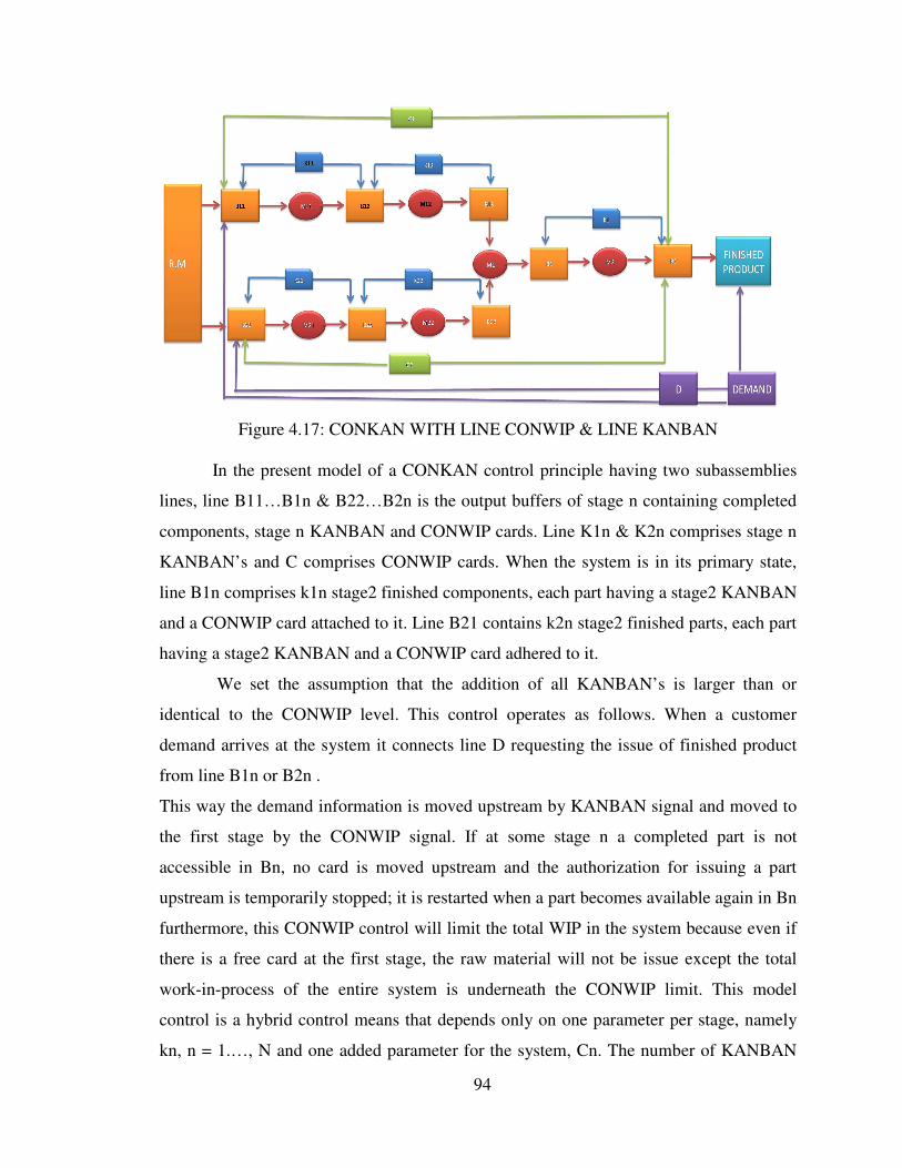
Figure 4.17: CONKAN WITH LINE CONWIP & LINE KANBAN
In the present model of a CONKAN control principle having two subassemblies
lines, line B11…B1n & B22…B2n is the output buffers of stage n containing completed
components, stage n KANBAN and CONWIP cards. Line K1n & K2n comprises stage n
KANBAN’s and C comprises CONWIP cards. When the system is in its primary state,
line B1n comprises k1n stage2 finished components, each part having a stage2 KANBAN
and a CONWIP card attached to it. Line B21 contains k2n stage2 finished parts, each part
having a stage2 KANBAN and a CONWIP card adhered to it.
We set the assumption that the addition of all KANBAN’s is larger than or
identical to the CONWIP level. This control operates as follows. When a customer
demand arrives at the system it connects line D requesting the issue of finished product
from line B1n or B2n .
This way the demand information is moved upstream by KANBAN signal and moved to
the first stage by the CONWIP signal. If at some stage n a completed part is not
accessible in Bn, no card is moved upstream and the authorization for issuing a part
upstream is temporarily stopped; it is restarted when a part becomes available again in Bn
furthermore, this CONWIP control will limit the total WIP in the system because even if
there is a free card at the first stage, the raw material will not be issue except the total
work-in-process of the entire system is underneath the CONWIP limit. This model
control is a hybrid control means that depends only on one parameter per stage, namely
kn, n = 1.…, N and one added parameter for the system, Cn. The number of KANBAN

95
and CONWIP influence both the transfer of completed components downstream through
the system and the transfer of parts upstream through the system.
Moreover, in this system, raw materials are transmitted to all stages directly upon
their arrival to the system as is the case in the BASE STOCK supply and KANBAN
control system, so that the demand data has never been blocked. A significant attribute of
the control system is that it introduces CONWIP control parameter for the whole system.
Figure 6.5: CONKAN WITH LINE CONWIP & LINE KANBAN

96
6.4.4 Implementation of Model 4 (CONKAN MULTI CONWIP WITH LINE
KANBAN & LOOP CONWIP) into Existing production system
Figure 6.6: CONKAN MULTI CONWIP WITH LINE KANBAN & LOOP CONWIP
In this model we used Individual CONWIP card for each assembly line
separately. Single CONWIP C1 for one subassembly line with main assembly line other
C2( CONWIP card) for second sub assembly & Main Assembly line. In this Model on
the main subassembly line two CONWIP card will work simultaneously and by this
method we can provide the better control system in assembly line where the sub assembly
line is big and important. As shown In Figure 4.18 ,C1 & C2 providing the control on
subassembly line and main assembly line but by providing two extra CONWIP Card C3
& C4 we will also provide the control on sub assembly line separately.

97
In the model of a CONKAN control principle having two subassemblies lines
,line B11…B1n & B22…B2n is the output buffers of stage n containing completed
components, stage n KANBAN’s and CONWIP cards(C1, C2, C3, C4,…,Cn). Line K1n
& K2n comprises stage n KANBAN’s and comprises CONWIP cards. When the system
is in its primary state, line B1n comprises k1n stage2 finished components, each part
having a stage2 KANBAN and a CONWIP card attached to it. Line B21 contains k2n
stage2 finished parts, each part having a stage2 KANBAN and a CONWIP card adhered
to it.
In this model also addition of all KANBAN card is larger than or identical to the
sum of CONWIP cards (C1, C2, C3, C4,…,Cn). Normally this control operates as
follows. When a customer demand arrives at the system it connects line D requesting the
issue of finished product from line B1n or B2n.
This way the customer demand information is moved upstream by KANBAN signal and
moved to the first stage by the CONWIP signal. If at some stage n a completed part is not
accessible in Bn, no card is moved upstream and the authorization for issuing a part
upstream is temporarily stopped; it is restarted when a part becomes available again in Bn
furthermore, this CONWIP control will limit the total WIP in the system because even if
there is a free card at the first stage, the raw material will not be issue except the total
work-in-process of the entire system is underneath the CONWIP limit.
This CONKAN model is a hybrid control means that depends not only on one
parameter per stage, namely Kn, n = 1,…, N and one added parameter for the different
line like C1,C2 ,C3,C4….Cn, The number of KANBAN and CONWIP cards influences
both the transfer of completed components downstream through the system and the
transfer of parts upstream through the system.
6.5 Operational System for Card Calculation
We developed news software based system for calculation of cards in for different
production line. It is easy to use and applicable in every conditions of Production.

98
Figure 6.7: System for New CONKAN System
In this System by the filling of data entry form, we can calculate the desired number of
cards.
Figure 6.8: Data Entry form in System

99
Figure 6.9: Identification form in System
In the CONKAN , system generated the report of KANBAN & CONWIP Card and the
inventory level.
Figure6.10: Report Generation

100
Once we calculated the quantities needed to support the production requirements, we
designed the CONKAN system .For designing of KANBAN & CONWIP card we used
the System the we selected the signaling mechanism for the CONKAN & Created a
visual management plan for the CONKAN Production system
Figure 6.11: Design of Card
6.6 Result of Implementation
In this case study we have focused on six factors i.e. production, rejection,
breakdown time, line inventory, throughput and OEE. This case study was conducted through

101
a series of observations, in-depth interviews, and documentation reviews. We examined the
Production capacity, machine failure time, WIP both before and after the implementation of
the different CONKAN Models and then analyzed the impact that this model on existing
production system. In this section first of all we collected observation regarding existing
system. In this observation we have observed fifteen shifts in which each shift contains
four hundred and twenty minutes.
Table 6.1: Summary Sheet of existing production system
Implementation of KANBAN System
In this case study firstly we examined the existing system and after the analysis of the
same we have implemented the KANBAN Production System. In table 5.2 we discussed
the results of implementation of KANBAN System and concluded that there are some
difference in the results of the existing system and KANBAN System. In the KANBAN
System six factors are improved. The increased factors are Production, Throughput and
OEE and the factors decreased are Rejection, Breakdown Time and Line Inventory. The
comparison has been already showed in the tables _____ and ______.
The table 1 presents the results of production system from implementation of
KANBAN in the assembly area.

102
Table 6.2: Summary Sheet of KANBAN production system
Implementation of CONWIP System
The table 2 presents the results of production system from implementation of
CONWIP Production System in the assembly area. Firstly we have implemented the
KANBAN System and similarly later we have implemented the CONWIP System in the
existing system with the same six factors we have focused in the implementation of
KANBAN System. The results we got are far much better than the comparison with the
KANBAN & existing system as well as the initially existing system.

103
Table 6.3: Summary Sheet of CONWIP Production system
104
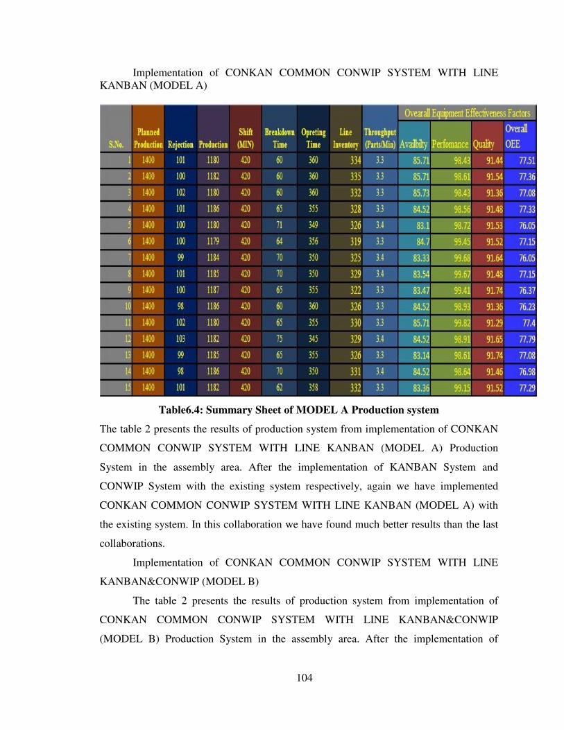
Implementation of CONKAN COMMON CONWIP SYSTEM WITH LINE
KANBAN (MODEL A)
Table6.4: Summary Sheet of MODEL A Production system
The table 2 presents the results of production system from implementation of CONKAN
COMMON CONWIP SYSTEM WITH LINE KANBAN (MODEL A) Production
System in the assembly area. After the implementation of KANBAN System and
CONWIP System with the existing system respectively, again we have implemented
CONKAN COMMON CONWIP SYSTEM WITH LINE KANBAN (MODEL A) with
the existing system. In this collaboration we have found much better results than the last
collaborations.
Implementation of CONKAN COMMON CONWIP SYSTEM WITH LINE
KANBAN&CONWIP (MODEL B)
The table 2 presents the results of production system from implementation of
CONKAN COMMON CONWIP SYSTEM WITH LINE KANBAN&CONWIP
(MODEL B) Production System in the assembly area. After the implementation of

105
CONKAN COMMON CONWIP SYSTEM WITH LINE KANBAN (MODEL A) with
the existing system we have implemented CONKAN COMMON CONWIP SYSTEM
WITH LINE KANBAN&CONWIP (MODEL B) with the existing system. Now we came
to the conclusion that the results of implementation of KANBAN System, CONWIP
System and CONKAN COMMON CONWIP SYSTEM WITH LINE KANBAN
(MODEL A) respectively were found better but the results of implementation of
CONKAN COMMON CONWIP SYSTEM WITH LINE KANBAN (MODEL A) and
CONKAN COMMON CONWIP SYSTEM WITH LINE KANBAN&CONWIP
(MODEL B) were very similar. Some of the factors in the six factors we have focused
were increasing and some were decreasing, like Breakdown Time, OEE and Throughput
is low and production is high in CONKAN COMMON CONWIP SYSTEM WITH LINE
KANBAN&CONWIP (MODEL B) in comparison to CONKAN COMMON CONWIP
SYSTEM WITH LINE KANBAN (MODEL A). whereas rejection is almost similar in
both the models.
Table 6.5: Summary Sheet of MODEL B Production system

106
Implementation of CONKAN WITH LINE CONWIP & LINE KANBAN
(MODEL C)
The table 2 presents the results of production system from implementation of
CONKAN WITH LINE CONWIP & LINE KANBAN (MODEL C) Production System
in the assembly area. If we compare this model with CONKAN COMMON CONWIP
SYSTEM WITH LINE KANBAN (MODEL A) and CONKAN COMMON CONWIP
SYSTEM WITH LINE KANBAN&CONWIP (MODEL B) we came to the conclusion
that Breakdown time in MODEL A is highest but it is lowest in MODEL B. but
production is high MODEL B but similar in MODEL A and C. Throughput is highest in
MODEL A, lowest in MODEL B but varying in MODEL C. OEE is highest in MODEL
C and Second highest in MODEL A. But in case of rejection all three models are almost
similar.
Table 6.6: Summary Sheet of MODEL C Production system

107
Implementation of CONKAN MULTI CONWIP WITH LINE KANBAN &
LOOP CONWIP (MODEL D)
The table 2 presents the results of production system from implementation of
CONKAN MULTI CONWIP WITH LINE KANBAN & LOOP CONWIP (MODEL D)
Production System in the assembly area. When we compare the last three models with the
MODEL D we can conclude that the Breakdown Timing is highest in MODEL A,
Lowest in MODEL B but similar in MODEL C and D. Production is MODEL B & D is
high but results similar in MODEL C and A. Throughput is highest in MODEL A and D
and lowest in MODEL B but varying in MODEL C. In case of OEE results, MODEL D
is the highest, MODEL C is the second highest, MODEL A stands at the third highest and
MODEL B stands at the lowest level.
Table 6.7: Summary Sheet of MODEL D Production system

108
6.7 Results and Discussion
We record & examined all the related data and after that we concluded that the
implementation of KANABN system is beneficial from existing but the CONWIP system
work better than KANBAN system.
In CONKAN system’s all models perform very well but no any one model is superior,
6.7.1 Production Comparison
We analyzed that in existing system the average production was 1107 units/ shift,
the minimum production was 1101 unit/ shift and maximum was 1115 unit/ shift. After
the implementation of KANABN it increased up to 1118 Unit/Shift and maximum
Production increased upto 1126 units/shift and minimum was 1107 units/shift.CONWIP
system also increased production upto 1137 units/ shift. After the analysis of figure 5.1
we can conclude that the average production per shift was maximum in CONWIP
system.
Figure 6.12: Production Comparison between Existing, KANBAN, CONWIP Models
When we compared our Models A,B, C& D, We find that in average production in
Model A & C is 1183 units/shift , 1182 Units/shift and in Model B & D average
production was 1190 units/shift.but the maximum production 1193units/shift in model D.
After the analysis of Figure 5.2 & 5.3 we can say that the Model B& C perform well for
increasing in the production.

109
Figure 5.13: Production Comparison between All CONKAN Models & Existing system
Figure 6.14: Production Comparison between all CONKAN Models

110
6.7.2 Break Down Time Comparison
In existing system the average breakdown time was 69 minutes /shift and maximum
breakdown was 86 minute/shift. After the implementation of KANBAN &CONWIP
SYSTEM the minimum average breakdown time was 60 minute/ shift in CONWIP
system where as in KANABN the Breakdown time slightly increased.
Figure 6.15: BD time Comparison between Existing, KANBAN, CONWIP Models
When we compared Model A& B, the average breakdown time 65 Minutes/shift in
Model A whereas in Model B 58 Minutes/ shift. In Model C & D, In Model D it average
Break down time was 61 Minutes /Shift and the minimum breakdown time was 55
minutes/shift.
Figure 6.16: BD time Comparison between All CONKAN Models

111
Figure 6.17: BD time Comparison between All CONKAN Models & Existing system
But when we compared Break down time with existing system, in Existing
system it was 69 Minutes/shift , whereas in Models it goes up to minimum level 61
Minutes/shift.
6.7.3 Throughput Comparison
When we compare between the existing system, KANBAN Production System and
CONWIP system, we came to the point that the throughput found in the existing system
is 3.15 parts/minute, in KANBAN Production System is 3.18 parts/minute and in
CONWIP System the throughput found is 3.25 parts/minute. The details shows the
regular improvement on the implementation of KANBAN Production system and then
CONWIP System.

112
Figure 6.18: Throughput Comparison between Existing, KANBAN, CONWIP Models
When we compare the implementation of MODEL A then MODEL B then C and finally
D, we came to the conclusion that the highest throughput we got is from MODEL A i.e.
3.33 parts/minute, Model D also gives the good result as 3.32 parts/minute and is on the
second position, but MODEL B shows the worst result as 3.29 parts/minute.
Figure 6.19: Throughput Comparison between All CONKAN Models

113
Now, if we compare all the four MODELS with the EXISTING System, we came to the
conclusion that all four MODELS gives the better performance then the EXISTING
System as Existing system gives throughput of avg. 3.15 parts/minute but all the four
MODELS gives avg. 3.33, 3.29, 3.31 & 3.32 parts/minute respectively.
Figure 6.20: Throughput Comparison between All CONKAN Models & Existing system
6.7.4 Work In Process Comparison
Now, if we come to the factor “Work in Process”, we came to the conclusion that it
decreases in KANBAN system in comparison to existing system and then again decreases
in the implementation of CONWIP system. The average readings per shifts foe existing,
KANBAN Production and CONWIP Systems are 446, 397 and 330 per shift respectively.
When we come to the comparison of WIP in all four MODELS, we came to the
conclusion that MODEL B & D gives 314 average readings per shift. But MODEL C
gives the highest WIP of 330 per shift and MODEL A gives the average of 328 per shift.
Then, when we talk about the comparison between the four MODELS and existing
System we found the difference, as about 120 per shift WIP found more in existing
System.

114
Figure 6.21: WIP Comparison between All CONKAN Models
Figure 6.22: WIP Comparison between All CONKAN Models & Existing system

115
6.7.5 O.E.E COMPARISON
The Overall equipment Effectiveness of the existing system is too low in comparison to
the KANBAN Production system and CONWIP system shows more effectiveness then
the existing and KANBAN system. the readings of existing, KANBAN and CONWIP
systems are 71.37%, 72.2% and 73.73% respectively.
The comparison between the four MODELS shows that in Model A it was 76.98 and in B
it increased upto 78.02.
Finally when we compared the all four models then we find out that the maximum O.E.E
in system was 78.04 in Model D and in Model B 78.02.
Figure 6.23: OEE Comparison between CONKAN Models

116
Figure 6.24: OEE Comparison between Existing, & CONKAN Models
6.7.6 Rejection Comparison
We compared the rejection in all models, then we find that in the existing system the
average rejection was 108 parts, whereas in KANBAN system it increases up to 109. But
when we implemented the CONWIP system the average rejection decreased up to 105.
117
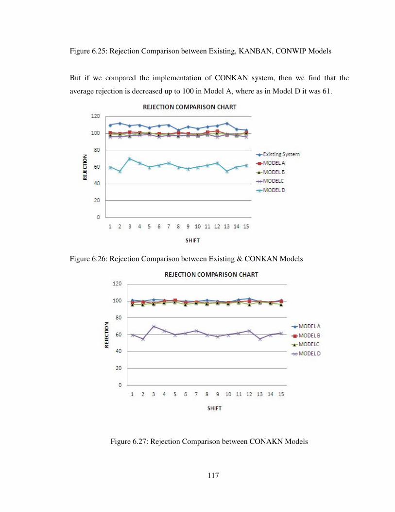
Figure 6.25: Rejection Comparison between Existing, KANBAN, CONWIP Models
But if we compared the implementation of CONKAN system, then we find that the
average rejection is decreased up to 100 in Model A, where as in Model D it was 61.
Figure 6.26: Rejection Comparison between Existing & CONKAN Models
Figure 6.27: Rejection Comparison between CONAKN Models

118
6.8 Conclusion
The goal of the case study was to implement CONKAN System in the Shock absorber
assembly line. The company has achieved tremendous benefits by implementing the
CONKAN System in the assembly area. It dramatically reduced the work in Progress (WIP),
break down time and rejection of parts. Whereas the throughput and OEE increased
significantly.
This case study showed that if we implemented the KANABN system & CONWIP system
then performance is increased but we implement the CONKAN system with all four models,
then the result showed that all models perform very well as compared to existing system and
all other control systems.