Chapter 5wqw
73
Page 179 5 Structural Design of Foundations Panchy Arumugasaamy CONTENTS 5.1 Introduction 179 5.2 Types of Foundations 180 5.3 Soil Pressure Distribution under Footings 183 5.4 Determination of the Size of Footing 185 5.4.1 Shear Strength of Footings 185 5.5 Strip or Wall Footings 190 5.6 Combined Footings 196 5.7 Pile Foundations 205 5.7.1 Analysis of Pile Groups 205 5.8 Design of Grade Beams 212 5.9 Structural Design of Drilled Shafts 214 5.9.1 Behavior of Drilled Shafts under Lateral Loads 215 5.9.2 Methodology for Design of Drilled Shafts 215 5.9.2.1 Brom’s Method of Design 216 References 233 5.1 Introduction Foundation substructures are structural members used to support walls and columns to transmit and distribute their loads to the ground. If these loads are to be properly transmitted, the substructure must be designed to prevent excessive settlement or rotation and to minimize differential settlement. In addition, it should be designed in such a way that the load bearing capacity of the soil is not exceeded and adequate safety against sliding and overturning is assured. Cumulative floor loads of a building, a bridge, or a retaining wall are supported by the foundation substructure in direct contact with soil. The soil underneath the substructure becomes compressed and deformed during its interaction with the substructure. This deformation is the settlement that may be permanent due to dead loads or may be elastic due to transition live loads. The amount of settlement depends on many factors, such as the type of soil, the load intensity, the ground water conditions, and the depth of substructure below the ground level.
description
qwrfefe
Transcript of Chapter 5wqw

Page 179
5Structural Design of Foundations
Panchy Arumugasaamy
CONTENTS
5.1 Introduction 179
5.2 Types of Foundations 180
5.3 Soil Pressure Distribution under Footings 183
5.4 Determination of the Size of Footing 185
5.4.1 Shear Strength of Footings 185
5.5 Strip or Wall Footings 190
5.6 Combined Footings 196
5.7 Pile Foundations 205
5.7.1 Analysis of Pile Groups 205
5.8 Design of Grade Beams 212
5.9 Structural Design of Drilled Shafts 214
5.9.1 Behavior of Drilled Shafts under Lateral Loads 215
5.9.2 Methodology for Design of Drilled Shafts 215
5.9.2.1 Brom’s Method of Design 216
References 233
5.1 Introduction
Foundation substructures are structural members used to support walls and columns totransmit and distribute their loads to the ground. If these loads are to be properly transmitted,the substructure must be designed to prevent excessive settlement or rotation and to minimizedifferential settlement. In addition, it should be designed in such a way that the load bearingcapacity of the soil is not exceeded and adequate safety against sliding and overturning isassured.
Cumulative floor loads of a building, a bridge, or a retaining wall are supported by thefoundation substructure in direct contact with soil. The soil underneath the substructurebecomes compressed and deformed during its interaction with the substructure. Thisdeformation is the settlement that may be permanent due to dead loads or may be elastic dueto transition live loads. The amount of settlement depends on many factors, such as the typeof soil, the load intensity, the ground water conditions, and the depth of substructure belowthe ground level.

If the soil bearing capacity is different under different isolated substructures or footings ofthe same building a differential settlement will occur. Due to uneven settlement of supportsthe structural system becomes over stressed, particularly at column beam joints.

Page 180
Excessive settlement may also cause additional bending and torsional moments in excess ofthe resisting capacity of the members, which could lead to excessive cracking and failures. Ifthe total building undergoes even settlement, little or no overstressing occurs.
Therefore, it is preferred to have the structural foundation system designed to provide evenor little settlement that causes little or no additional stresses on the superstructure. The layoutof the structural supports varies widely depending upon the site conditions. The selection ofthe type of foundation is governed by the site-specific conditions and the optimal constructioncost. In designing a foundation, it is advisable to consider different types of alternativesubstructures and arrive at an economically feasible solution. In the following sections, thedesign of a number of commonly used reinforced concrete foundation system types ispresented. The reader is advised that, in keeping with the structural design practices in theUnited States, the English standard measurement units are adopted in the design proceduresoutlined in this chapter. However, the conversion facility in Table 5.1 is presented for theconvenience of readers who are accustomed to the SI units.
5.2 Types of Foundations
Most of the structural foundations may be classified into one of the following types:
1. Isolated spread footings: These footings are used to carry individual columns. These maybe square, rectangular, or occasionally circular in plan. The footings may be of uniformthickness, stepped, or even have sloped top (Figure 5.1) and reinforced in both directions.They are one of most economical types of foundation, when columns are spaced at arelatively long distance.
2. Wall footings: They are used to support partitions and structural masonry walls that carryloads from floors and beams. As shown in Figure 5.2, they have a limited width andcontinuous slab strip along the length of the wall. The critical section for bending is locatedat the face of the wall. The main reinforcement is placed perpendicular to the wall direction.Wall footings may have uniform thickness, be stepped, or have a sloped top.
TABLE 5.1
Unit Conversion Table
From English To SI Multiply by Quantity From SI To English Multiply bylbs/ft3 N/m3 157.1 Force/unit- volume N/m3 lbs/ft3 0.0064
kips/ft3 kN/m3 157.1 kN/m3 kips/ft3 0.0064
lb-in. N mm 112.98 Moment; or energy N mm lb-in. 0.0089
kip-in. kN mm 112.98 kN mm kip-in. 0.0089
lb-ft Nm 1.356 Nm lb-ft 0.7375
kip-ft kN 1.356 kN kip-ft 0.7375
ft-lb Joule 1.356 Joule ft-lb 0.7375
ft-kip kJ 1.356 kJ ft-kip 0.7375
sec/ft sec/m 3.2808 Damping sec/m sec/ft 0.3048
Blows/ft Blows/m 3.2808 Blow count Blows/m Blows/ft 0.3048

Source: Courtesy of the New York Department of Transportation.

Page 181
FIGURE 5.1
Isolated spread footing: (a) plan; (b) elevation.
FIGURE 5.2
Wall footing: (a) plan; (b) elevation.

Page 182
FIGURE 5.3
Combined rectangular footings: (a) equal column loads PA=PB; (b) unequal column loads PB>PA.
3. Combined footings: This type is used to support two or more column loads. They may becontinuous with a rectangular or trapezoidal plan. The combined footing becomesnecessary in situations where a wall column has to be placed on a property line that may becommon in urban areas. Under such conditions, an isolated footing may not be suitablesince it would have to be eccentrically loaded. It is more economical to combine theexterior column footings with an interior column footing as shown in Figure 5.3. Thecombined footings are more economical to construct in the case of closely spaced columns.
4. Cantilever footings: They are basically the same as combined footings except that they areisolated footings joined by a strap beam that transfers the effect of the bending momentproduced by the eccentric column load at the exterior column (possibly located along theproperty line) to the adjacent interior column footing that lies at a considerable distancefrom it. Figure 5.4 shows an example of such a cantilever footing.
5. Mat, raft, or continuous footing: This is a large continuous footing supporting all of thecolumns and walls of a structure as shown in Figure 5.5. A mat or a raft footing is usedwhen the soil conditions are poor and a pile foundation is not economical. In this case, thesuperstructure is considered to be theoretically floating on a mat or raft. This type ofstructure is basically an inverted floor system.
FIGURE 5.4
Strap or cantilever footing: (a) plan; (b) elevation.

Page 183
FIGURE 5.5
Raft or mat foundation: (a) plan; (b) elevation.
FIGURE 5.6
Pile foundation: (a) plan; (b) elevation.

6. Pile foundations: This type of foundation becomes essential when the supporting soilconsists of poor layers of material to an extended depth such that an individual or matfoundation is not feasible. Figure 5.6 shows an example of such a footing.
5.3 Soil Pressure Distribution under Footings
The soil pressure distribution under a footing is a function of relative rigidity of thefoundation, type, and stiffness of the soil. A concrete footing on cohesionless (sandy) soil willexhibit a pressure distribution similar to the one shown in Figure 5.7(a). The sand near theedges of the rigid footing tends to displace outward laterally when the footing is loadedwhereas the rigid footing tends to spread pressure uniformly. On the other hand, the pressuredistribution under a rigid footing in cohesive (clay) soil is similar to that shown in Figure5.7(b). When the footing is loaded, the clay under the footing deflects in a bowl-shapeddepression, relieving the pressure under the middle of the footing. However, for designpurposes it is customary to assume that the soil pressures are linearly distributed, such that theresultant vertical soil force is collinear with the resultant applied force as shown in Figure5.7(c).
To simplify the foundation design, footings are assumed to be rigid and the supporting soillayers elastic. Hence, the soil pressure under a footing is determined assuming linearly elasticaction in compression. It is also assumed that there is no tensile strength

Page 184
FIGURE 5.7
Pressure distribution under regular footings in different soil types: (a) pressure distribution in sandysoil; (b) pressure distribution in clayey soil; (c) simplified pressure distribution.
across the contact area between the footing and the soil. If a column footing is loaded withaxial load P at or near the center of the footing, as shown in Figure 5.8, the contact pressure qunder the footing is simply P/A. On the other hand, if the column is loaded with an axial loadP and a moment of M, the stress under the footing is
q=P/A±MY/I(5.1)
where q is the soil pressure under the footing at any point, P is the applied load, A is the areaof footing=BD (B is the width of footing and D is the length of footing), M is the moment, Y isthe distance from centroidal axis to point where the stress is computed, and I is the secondmoment of area of the footing (I=BD3/12).
If e is the eccentricity of the load relative to the centroidal axis of the area A, the moment Mcan be expressed as Pe. The maximum eccentricity e for which Equation (5.1) applies is theone that produces q=0 at some point. However, the larger eccentricities will cause a part ofthe footing to lift of the soil. Generally, it is not preferred to have the footing lifted since itmay produce an uneconomical solution. In cases where a larger moment is involved, it isadvisable to limit the eccentricity to cause the stress q=0 condition at

Page 185
FIGURE 5.8
Pressure distribution under eccentric footings.
the edge of the footing. This will occur when the eccentricity e falls within the middle third ofthe footing or at a limit B/6 or D/6 from the centroidal point of footing. This is referred to asthe kern distance. Therefore, the load applied within the kern distance will producecompression under the entire footing.
5.4 Determination of the Size of Footing
The footings are normally proportioned to sustain the applied factored loads and inducedreactions that include axial loads, moments, and shear forces that must be resisted at the baseof the footing or pile cap, in accordance with appropriate design requirements of theapplicable codes. The base area of the footing or the number and the arrangement of piles areestablished after the permissible soil pressure or the permissible pile capacity has beendetermined by the principles of soil mechanics as discussed in Chapters 3, 4, and 6, on basisof unfactored (service) loads such as dead, live, wind, and earthquake, whatever thecombination that governs the specific design. In the case of footings on piles, the computationof moments and shear could be based on the assumption that the reaction from any pile isconcentrated at the pile center.
5.4.1 Shear Strength of FootingsThe strength of footing in the vicinity of the columns, concentrated loads, or reactions isgoverned by the more severe of two conditions: (a) wide beam action with each criticalsection that extends in a plane across the entire width needed to be investigated; and (b)footing subjected to two-way action where failure may occur by “punching” along a truncatedcone around concentrated loads or reactions. The critical section for punching shear has aperimeter b0 around the supported member with the shear strength computed in accordancewith applicable provision of codes such as ACI 11.12.2. Tributary areas and correspondingcritical sections for both wide-beam and two-way actions for isolated footing are shown inFigure 5.9.

Page 186
FIGURE 5.9
Tributary area and critical section for shear.
For footing design with no shear reinforcement, the shear strength of concrete Vc (i.e., Vn=Vc)is considered as the smallest of the following for two way action.
(5.2)
(5.3)
(5.4)
where b0 is the perimeter of critical section taken at d/2 from the loaded area
b0=2(c1+c2)+4d(5.5)
d is the effective depth of the footing, βc is the ratio of the long side to the short side of theloaded area, and αs=40 for interior columns, 30 for edge columns, and 20 for corner columns.
In the application of above ACI Equation 11–37, an “interior column” is applicable whenthe perimeter is four-sided, an “edge column” is applicable when the perimeter is three-sided,and finally a “corner column” is applicable when the perimeter is two-sided.
Design Example 5.1Design for base area of footing (Figure 5.10).

FIGURE 5.10
Illustration for Example 5.1.

Page 187
Problem StatementDetermine the base area Af required for a square footing of a three-storey building interior
column with the following loading conditions:
Service dead load=400 kipsService live load=280 kipsService surcharge (fill)=200 psfPermissible soil pressure=4.5 ksfColumn dimensions=24×15 in.
SolutionThe base area of the footing is determined using service (unfactored) loads with the net
permissible soil pressure.1. Determination of base area:Let us assume that the bottom of the footing is 4 ft below the ground level:
Average weight of soil=125.00 pcfTotal weight of surcharge=(0.125×4)+0.2=0.70 ksfPermissible soil pressure=4.50 ksfNet permissible soil pressure=4.5−0.7=3.80 ksf
Given
Service DL=400.00 kipsService LL=280.00 kips
Required base area of footing:
Use a 13'−6″×13'−6″square footing, Af=182.25 ft2.2. Factored loads and soil reaction:To proportion the footing for strength (depth and area of steel rebar) factored loads are
used:
Safety factor for DL=1.40Safety factor for LL=1.70
Pu=1.4(400)+1.7(280)=1036 kipsqs=5.68 ksf
Example 5.2For the design conditions of Example 5.1, determine the overall thickness of footing and
the required steel reinforcement given that psi and fy=60,000 psi (Figure 5.11).

Page 188
FIGURE 5.11
Illustration for Example 5.2.
Safety factor for DL=1.40Safety factor for LL=1.70
Pu=1.4(400)+1.7(280)−1036 kipsqs=5.68 ksf
SolutionDetermine depth of shear based on the shear strength without any shear reinforcement.
Depth required for shear usually controls the footing thickness. Both wide-beam action andtwo-way action for strength computation need to be investigated to determine the controllingshear criteria for depth.
Assume overall thickness, h=36.00 in.Clear cover to the rebar=4.00 in.Assumed rebar diameter=1.00 in.Effective diameter, d=31.50 in.
(a) Wide-beam actionVu=qs×tributary areabw=162.00 in.Tributary area=13.5(13.5/2−15/24−31/12)=47.81 ft2

Page 189
(b) Two-way actionVu=qs×tributary areaTributary area=(13.5×13.5)−(24+31)(15+31)/144]−164.68 ft2
Vu=5.68×164.68=936.13 kips
First determine the minimum of all three conditions as given below:
(i) 2+4/βc=2+4/1.6, βc=24/15=1.60 =4.50(ii) 2+αsd/b0=2+40×31/202, b0=2(24+31)+2(15+31)=202 in. =8.14(iii) 4 (control)
Hence, the assumed total depth of 36 inch is OK.
(c) Determination of reinforcement
qs=5.68 kips
b=13.5 ft
d=31 in.
(i) Critical section for moment is at the face of column:
Mu=5.68×13.5×(13.5/2–15/24)2/2
=1439.488 ft-kips
(ii) Compute the required area of reinforcement As as follows: Compute
where
Check for ρmin=0.0018<0.002115 (provided), OKUse 14 #8 bars each way, As=11.06 in.2
Note that less steel is required in the perpendicular direction, but for ease of barplacement use the same number of bars in the other direction.

(iii) Check for development of reinforcement:The critical section for development of reinforcement is the same as for the moment (atthe face of the column). However, the reinforcing bar should resist
Page 190
FIGURE 5.12
Determination of reinforcement for Example 5.2.
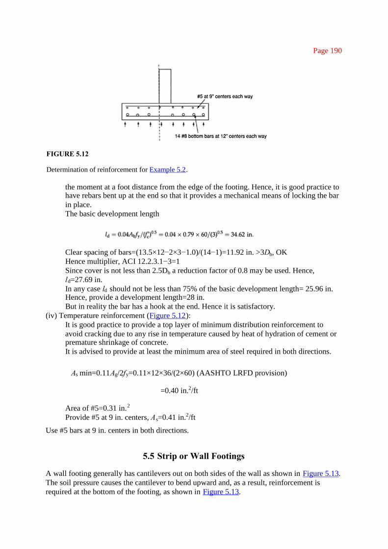
the moment at a foot distance from the edge of the footing. Hence, it is good practice tohave rebars bent up at the end so that it provides a mechanical means of locking the barin place.The basic development length
Clear spacing of bars=(13.5×12−2×3−1.0)/(14−1)=11.92 in. >3Db, OKHence multiplier, ACI 12.2.3.1−3=1Since cover is not less than 2.5Db a reduction factor of 0.8 may be used. Hence,ld=27.69 in.In any case ld should not be less than 75% of the basic development length= 25.96 in.Hence, provide a development length=28 in.But in reality the bar has a hook at the end. Hence it is satisfactory.
(iv) Temperature reinforcement (Figure 5.12):It is good practice to provide a top layer of minimum distribution reinforcement toavoid cracking due to any rise in temperature caused by heat of hydration of cement orpremature shrinkage of concrete.It is advised to provide at least the minimum area of steel required in both directions.
As min=0.11Ag/2fy=0.11×12×36/(2×60) (AASHTO LRFD provision)
=0.40 in.2/ft
Area of #5=0.31 in.2
Provide #5 at 9 in. centers, As=0.41 in.2/ft
Use #5 bars at 9 in. centers in both directions.
5.5 Strip or Wall Footings
A wall footing generally has cantilevers out on both sides of the wall as shown in Figure 5.13.The soil pressure causes the cantilever to bend upward and, as a result, reinforcement isrequired at the bottom of the footing, as shown in Figure 5.13.

Page 191
FIGURE 5.13
Structural action in a wall footing.
The critical sections for design for flexure and anchorage are at the face of the wall (sectionA–A in Figure 5.13). One-way shear is critical at the section at a distance d from the face ofthe wall (section B-B in Figure 5.13).
Example 5.3A 8-in. thick wall is a part of a vertical load carrying member of an eight-storey
condominium and hence carries seven floors and the roof. The wall carries a service(unfactored) dead load of 1.5 kips per foot per floor including the roof and a service live loadof 1.25 kips per foot per floor. The allowable soil net bearing pressure is 5.0 ksf at the level ofthe base of the footing, which is 5 ft below the ground surface. The floor-to-floor height is 10ft including the roof. Design the wall footing assuming psi and fy=60,000 psi.
Solution
(1) Estimate the total service load. Consider 1-ft width of the wallDead load from self weight of the wall Wd1=(8×10+5: height)×(8/12: thicknesswall)×(0.15 kips/ft)
Wd1=8.50 kips/ft
Dead load from floors
Wd2=8×1.5=12.00 kips/ft
Total DL=Wd1+Wd2=8.5+12.0
=20.50 kips/ft
Liveload=8×1.25
=10.00 kips/ft
Note that the net bearing pressure at the footing level is given, and hence the self-weight of the footing does not need to be considered.
(2) Compute the width of the wall

Try a footing 6 ft 4 in. wide; w=6.33

Page 192
Factored net pressureIn the design of the concrete and reinforcement, we will use qu=7.22 ksf.
(3) Check for shearShear usually governs the thickness of footing. Only one-way shear is significant for awall footing. We need to check it at a distance d away from the face of the wall (sectionB–B in Figure 5.13).Now let us assume a thickness of footing=16 in.
d=16−3 (cover)−0.5 (bar diameter)
=12.5 in.
Clear cover (since it is in contact with soil)=3 in.
Since the footing depth is satisfactory.(4) Design of reinforcement
The critical section for moment is at the face of the wall section A–A in Figure 5.13.The tributary area for moment is shown shaded in Figure 5.14.
FIGURE 5.14
Plan view of footing (Example 5.3).

Page 193
Let us assume j=0.9, jd=11.25
From ACI sections 10.5.3 and 7.12.2Minimum As=0.0018bh=0.0018×12×16−0.35 in.2/ftSpacing of #5 bars at 6-in. centers, As=0.62 in.2/ft; provide #5 bars at 6-in. centers.Maximum spacing allowed in the ACI section 7.6.5=3h or 18 in.Now compute
The design is satisfactory (Figure 5.15).(5) Check the development length
Basic development length for #5 bars in 3,000 psi concrete=ldbACI code provision: furnish the following criterion:
ACI 12.2.3. (a) No transverse steel (stirrups): does not apply(b) and (c) Do not apply if flexural steel is in the bottom layer(d) Cover=3 in. and clear spacing=5.325 in. >3db and therefore 12.3.3.1 (d) applies ×1.0ACI 12.2.3.4. Applies with a factor of 0.8
FIGURE 5.15
Configuration of reinforcement layout (Example 5.3).

Page 194
ACI 12.2.4. Bottom bar, ×1.0; normal weight concrete, ×1.0; and standard deformed bar,×1.0
ldb=14×1.0×0.8=10.87 in.
ACI 12.2.3.6.The length of the bar from the maximum stress point at the face of the wall is 34 −3=31in., which is >21 in. and hence is satisfactory.
(6) Temperature and shrinkage ACI 7.12.2
As=0.0018bh=0.0018×12×16
=0.35 in.2
At least two thirds of this should be placed as top reinforcement in the transversedirection as the concrete exposed to the dry weather (low humidity and hightemperature) until covered.Provide #5 at 12-in. centers; As=0.31 in.2/ft and is thus satisfactory
As=0.0018bh=0.0018×76×12
=1.64 in.2/ft
This reinforcement should be divided between top and bottom layers in the longitudinaldirection (Figure 5.16).Provide 6 #4 at 14-in. centers both top and bottom
As=6×2×0.2=2.40 in.2/ft
>1.64 in.2/ft and hence is satisfactory
Example 5.4You have been engaged as an engineer to design a foundation for a three-storey office
building. It is required that the footings are designed for equal settlement under live loading.The footings are subjected to dead and live loads given below. However, statistics show thatthe usual load is about 50% for all footings. Determine the area of footing required for abalanced footing design. It is given that the allowable net soil bearing pressure is 5 ksf (Table5.2–Table 5.4).

FIGURE 5.16
Details of reinforcement (Example 5.3).

Page 195
Solution
TABLE 5.2
Details of Loads (Example 5.4)
Footing number 1 2 3 4 5 6
Dead load (kips) 130 170 150 190 140 200
Live load (kips) 160 210 200 180 210 250
TABLE 5.3
Computation of Load Ratios (Example 5.4)
Footing number 1 2 3 4 5 6
Ratio 1.231 1.235 1.333 0.947 1.500 1.250
TABLE 5.4
Computation of Factored Loads (Example 5.4)
Footing number 1 2 3 4 5 6
Usual load (DL+0.5LL) (kips) 210 275 250 280 245 325
(a) Determine the footing that has the largest ratio of live load to dead load. Note that thisratio is 1.5 for footing #5.
(b) Calculate the usual load for all footings.(c) Determine the area of footing that has the highest ratio of LL to DL (footing #5)
Area of footing #5=(DL+ LL)/(allow soil pressure)
Usual soil pressure under footing #5=(usual load)/(area of footing)
(e) Compute the area required for each footing by dividing its usual load by the usual soilpressure footing #5. For example, for footing #1,
Required area=210/3.5=60 ft2
For other footings, the computations are shown below:
TABLE 5.5

Computation of Areas (Example 5.4)Footing number 1 2 3 4 5 6
Usual load (DL ± 0.5LL) (kips) 210 275 250 280 245 325
Required area (ft2) 60 78.57 71.43 80.00 70.00 92.86
TABLE 5.6
Computation of Soil Pressure (Example 5.4)
Footing number 1 2 3 4 5 6
Soil pressure (ksf) 4.83 4.84 4.90 4.63 5.00 4.85

Page 196
(f) For verification, compute the soil pressure under each footing for the given loads.Note that the soil pressure under footing #5 is 5 ksf, whereas under other footings it is lessthan 5 ksf.
5.6 Combined Footings
Combined footings are necessary to support two or more columns on one footing as shown inFigure 5.17. When an exterior column is relatively close to a property line (in an urban area)and a special spread footing cannot be used, a combined footing can be used to support theperimeter column and an interior column together.
The size and the shape of the footing are chosen such that the centroid of the footingcoincides with the resultant of the column loads. By changing the length of the footing, thecentroid can be adjusted to coincide with the resultant loads. The deflected shape and thereinforcement details are shown for a typical combined footing in Figure 5.17(b) and anexample is given below to further illustrate the design procedure of such combined footings.
FIGURE 5.17
Typical combined footing: (a) under unloaded conditions; (b) under loaded conditions.

Page 197
Example 5.5In a three-storey building, an exterior column having a section of 24 in.×18 in. carries a
service dead load of 70 kips and service live load of 50 kips at each floor. At the same timethe nearby 24 square interior column carries a service dead load of 100 kips and a live load of80 kips at each floor. The architects have hired you as an engineer to design the footing forthese columns. The specific site condition dictates that a combined footing be chosen as aneconomical solution. Both columns carry three floors above them and are located 18 ft apart.The geotechnical engineer has advised that the soil bearing pressure at about 4 ft below theground is 5 ksf. The ground floor, which is going to be slab on grade with 6 in. concrete,supports a service live load of 120 psf. The soil below this floor is well compacted. Theavailable concrete strength psi and steel strength fy=60,000 psi. Design aneconomical footing.
SolutionStep 1. Determine the size and the factored soil pressure (Figure 5.18)
Distance from the external face of the exterior column=129.6+9 in.=139 in.=11.55ftWidth of the footing=208.09/(2×11.55)=9ftFactored external column load=3×(1.4×70+1.6×50) kips=534.00 kipsFactored internal column load=3×(1.4×100+1.6×80) kips=804.00 kipsTotal=1338.00 kipsNow we can compute the net factored soil pressure which is required to design the footing.
FIGURE 5.18
Factored load and factored net soil pressure (Example 5.5).

Page 198
FIGURE 5.19
Shear force diagram (Example 5.5) (forces in kips).
Step 2. Draw the shear force and bending moment diagram (Figure 5.19) If shear is zero atX1
Step 3. Determine the thickness of footing (Figure 5.20)In this case, the footing acts as a wide (9 ft) heavy duty beam. It is better to determine the
thickness based on the moment and check it for shear. We can start with minimumreinforcement of 200/fy as per ACI Section 10.5.1.
and
Therefore,

Page 199
FIGURE 5.20
Bending moment diagram (Example 5.5).
Now we will choose the total depth h=40 in. and the area of steel will be more than minimumsteel required.
h=40.00 in.d=40−4 (cover to reinforcement of 3 in. and 1 in. for reinforcement) =36.00 in.Step 4. Check two-way shear at the interior columnThe critical perimeter is a square with sides 24 in.+36 in.=60.00 in.Therefore,
b0=4×60=240.00 in.
The shear, Vu, is the column load corrected for (minus) the force due to the soil pressure onthe area enclosed by the above perimeter, see Figure 5.21.
is the smallest of the following:
(a)
(b)(c)
FIGURE 5.21
Shear perimeter (Example 5.5 Interior Column).

Page 200
Since Vu is less than the smallest value of 1609 kips of all three above conditions, the depth ofthe footing is adequate to support the interior square column load.
Step 5. Check two-way shear at the exterior columnThe critical perimeter is a rectangle with sides of 24+36=60.00 in. and a width of 18+
36/2=36.00 in. The shear, Vu, is the column load minus the force due to the soil pressure onthe area enclosed by the above perimeter
The shear perimeter around the column is three-sided, as shown in Figure 5.22. The distancefrom line B–C to the centroid of the shear perimeter is given by X2
The force due to the soil pressure on the area enclosed by the perimeter is
=6.43×(60×36/144)−96.45 kips
Then, summing up the moment about the centroid of the shear perimeter gives
Mu=534×(36−9.82−9)−96.45×(18−9.82)=8385.16 in.-kips
FIGURE 5.22
Illustration of the shear perimeter (Example 5.5 (a) Exterior column; (b) interior column).

Page 201
This moment must be transferred to the footing through shear stress and flexure. The momentof inertia of the shear perimeter jc is
jc=2[[36×363/12]+[36×363/12]+[36×36][18–9.822]]+[(60×36)×9.822]jc=646590.5+208293.984=854884.5 in.4
The fraction of moment transferred by flexure is
The fraction transferred by shear=(1−γf)=(1–0.659)=0.341The shear stress due to the direct shear and due to moment transfer will be additive at
points A and D in Figure 5.22, giving the largest shear stresses on the critical shear perimeter
Now we will compute from the following condition using ACI equations 11–36 to 11–38,which is the smallest of the following:
(a)
(b)(c)
Since Vu is less than the smallest value of 0.186 ksi of all the above three conditions, the depthof the footing is adequate to support the interior square column load.
Step 6. Check one-way shearThe shear force diagram shows that the maximum shear is near the exterior column and,
hence, one-way shear is critical at a distance d from the face of the exterior column:
Since Vu is less than the depth is adequate to support the required shear condition.Step 7. Design the flexural reinforcement
(a) The mid-span (negative moment):

Page 202
Per ACI handbook,
Provide #8 bars at 6-in. spacing at the top. Total area As=14.137 in.2
(b) At the face of interior column (positive moment):
Per ACI handbook,
Provide #8 bars at 6-in. spacing at the bottom. Total area As=14.137 in.2, which is satisfactory.Check for minimum area of steel required=(200/fy)bd=12.96 in.2
Since the provided area of steel is greater than the minimum steel required, the flexuralreinforcement provided is adequate.
Step 8. Check the development lengthBasic development length ldb for #8 bars in 3000 psi concrete (ACI code provision) is given
by
ACI 12.2.3.1:
(a) No transverse steel (stirrups): does not apply(b) Does not apply(c) Does not apply if flexural steel is in the bottom layer(d) Cover=3 in. and clear spacing=5.0 in >3db and therefore 12.3.3.1 (d) applies with a factor
of 1.0
ACI 12.2.3.4 Applies with a factor of 0.8ACI 12.2.4 Bottom bar,×1.0; normal wt concrete,×1.0; and standard deformed bar,×1.0ACI 12.2.4.1 Top bar with a factor of 1.3
ldb=35×1.0×0.8×1.3=36 in. (top bar)

Page 203
ACI 12.3.3.6The length of the bar from the maximum stress point at the face of the columns is 67–3 =64
in., which is >36 in. and hence is satisfactory.Step 9. Temperature and shrinkage reinforcement (ACI 7.12.2)
As=0.0018bh=0.0018×12×40= 0.86 in.2/ft
At least two thirds of this should be placed as top reinforcement in the transverse direction asthe concrete exposed to the dry and hot weather until covered by earth (backfill).
Provide #7 at 12 in. on centers; As=0.6 in.2/ft
As=0.0018bh=0.0018×12×40=0.86 in.2/ft
This reinforcement should be divided between the top and the bottom and should provide twothirds of it at the top since it will be exposed to temperature and half of it at the bottom layersin the longitudinal direction or provide 6 #7 at 12-in. centers at the top at the interior columnand at the bottom at the exterior column.
As=2×0.61–1.22 in.2/ft>0.86 in.2/ft, satisfactory
Step 10. Design of the transverse “beam”The transverse strips under each column will be assumed to transmit the load evenly from
the longitudinal beam strips into the column strip. The width of the column strip will beassumed to extend d/2 on either side of the interior column and one side of the exteriorcolumn (Figure 5.23).
(a) The maximum factored load for the interior column=804 kips This load is carried by a 9-ftbeam and, hence,
FIGURE 5.23
Cross section of beam (Example 5.5).

Page 204
Per ACI handbook,
Provide #8 bars at 6-in. spacing at the bottom. This amounts to a total of ten bars
Total As=7.85 in.2, Satisfactory
(b) The maximum factored load for the interior column=534 kipsThis load is carried by a 9-ft beam and, hence, load per ft=534/9
Per ACI handbook,
Provide #8 bars at 6-in. spacing at the bottom. This amounts to a total of seven bars
As=5.50 in.2 satisfactory
Step 11. Details of reinforcement (Figure 5.24)

Page 205
FIGURE 5.24
Details of reinforcement (Example 5.5).
5.7 Pile Foundations
A structure is founded on piles if the soil immediately below its base does not have adequatebearing capacity, or if the foundation cost estimate indicates that a pile foundation may bemore economical and safer than any other type of foundation. In this discussion, we willconsider only piles that are commonly available and driven into the ground by a mechanicaldriving devise known as a pile driver. Please note that the general principles are alsoapplicable to other types of pile foundations, with minor modifications. Piles may be dividedinto three categories based on the method of transferring the load into the ground (Figure5.25–Figure 5.28):
1. Friction piles in coarse-grained very permeable soils: These piles transfer most of theirloads to the soil through skin friction. The process of driving such piles close to each other(in groups) greatly reduces the porosity and compressibility of the soil within and aroundthe group.
2. Friction piles in very fine-grained soils of low permeability: These piles also transfer theirloads to the soils through skin friction. However, they do not compact the soil duringdriving as in case 1. Foundations supported by piles of this type are commonly known asfloating pile foundations.
3. Point bearing piles: These piles transfer their loads into a firm stratum or a soil layer.Depending on the geographical location, these piles have to be driven to a considerabledepth below the base of the footing.
In practice, piles are used to transfer their loads into the ground using a combination of theabove mechanisms.
5.7.1 Analysis of Pile GroupsThe function of a pile cap, a relatively rigid body, is to distribute the loads to each pile in agroup of piles. The loads could be vertical or horizontal loads or moments from thesuperstructure. The horizontal forces at the base are generally resisted by battered or rakedpiles. The batter can be as steep as 1 on 1, but it is economical to limit the batter to

Page 206
1.0 horizontal to 2.5 vertical (approximately 22° of an inclination to vertical). The horizontalforces may be carried by vertical piles in the form of shear and moments. The shear capacityof piles is limited by the material property of the pile. However, it is advisable to resist by thehorizontal component of the axial load in a battered pile.
When a footing consisting of N number of piles is subjected to a vertical load of P,moments of Mx and My, and a horizontal force of H, the following equation can be used todetermine the force attributed to each pile. After determining the force in each pile, thehorizontal resistance force may be provided by battering or raking the piles to developadequate horizontal resistance:
(5.6)
where P is the total vertical load in the pile cap, Mx is the moment at the pile cap about the x-axis, My is the moment of the pile cap about the y-axis, dx is the x-directional distance of thepile from the center of the pile group, and dy is the y-directional distance of the same pile fromthe center of the pile group.
The above principle is illustrated by the following example in an actual design situation.Example 5.6You have been engaged as the engineer to design the footing of a pier foundation for a
major bridge. The bridge engineer has determined that the foundation needs to be designed fora factored load of 3650 kips, a transverse factored moment of 7050 ft-kips, and a longitudinalmoment of 2400 ft-kips. The bridge pier is 8 ft (longitudinal direction) ×10 ft (transversedirection). The bridge engineer has proposed to use 18-in. square PC piles. The geotechnicalengineer has recommended limiting the pile capacity to 325 kip (factored load). The grouphas to resist a lateral force of 125 kips in the transverse direction and 75 kips in thelongitudinal direction. The bridge engineer has estimated that 17 to 18 piles would beadequate. The shear capacity of the 18-in. square pile is limited to 10 kips.
SolutionThis is a bridge foundation design example and hence AASHTO provisions apply:
1. Determine the number of piles and the spacing required to resist the given loadingcondition. It is given that the bridge engineer presumes that 18 piles would be required. Thespacing between piles is more than three times the pile diameter=3×18=54 in. Provide pilesat spacing of 60 in. (5 ft) in both directions.
2. Determine the size of the pile cap or the footing. Careful study of the situation indicatesthat the pile cap should provide higher resistance in the transverse direction. An edgedistance of 2 ft should be sufficient. If the pile group is arranged with five piles in thetransverse direction and four piles in the longitudinal direction,
Length of the pile cap=4×5ft+2×2ft=24ftWidth of the pile cap=3×5ft+2×2=19fth=5.00 ft

d=3.75 ftL=24.00 ftB=19.00 ft
3. Analysis of pile group.Analysis of the pile group can be carried out in a tabular form as given below:Pile load analysis—Transverse direction (Table 5.7)Pile load analysis—Longitudinal direction (Table 5.8)Combined loading effect: Load per pile (kips) (Table 5.9)
4. Consider one-way shear action:Critical section for shear=d from the face of the piles
FIGURE 5.25
Arrangement of piles and the pile cap.
TABLE 5.7
Computations for Transverse Directional Analysis
N X d2 N×d2 Pu kips3650.00
My ft-kips7050.00
Pu±My kips Mx ft-kips2400.00
4 10 100 400 202.78 70.50 273.28
4 5 25 100 202.78 35.25 238.03
2 0 0 0 202.78 0.00 202.78
4 −5 25 100 202.78 −35.25 167.53
4 −10 100 400 202.78 −70.50 132.28
Total 18 1000


Page 208
5. Consider two-way shear action:
6. Flexural behavior—Determination of reinforcements in the longitudinal direction:Minimum cover to reinforcement=3 in.
FIGURE 5.26
Pile cap layout—longitudinal direction.
TABLE 5.8
Computations for Longitudinal Directional Analysis
N X d2 N×d2 Mx ft-kips5 7.5 56.25 281.25 29.39
4 2.5 6.25 25 9.80
4 −2.5 6.25 25 −9.80
5 −7.5 56.25 281.25 −29.39
Total 612.5
TABLE 5.9Computations of Combined Analysis

Transverse
Longitudinal T1 T2 T3 T4 T5L1 161.67 196.92 232.17 267.42 302.67 1160.85
L2 142.07 177.32 247.82 283.07
L3 122.48 157.73 228.23 263.48
L4 102.89 138.14 173.39 208.64 243.89
Notes: Horizontal force=8.10 kips; high load on a pile=302.67 kips. Σ=1093.11 kips

Page 209
Number of #10 bars=26 barsSpacing=8.15 in. in the longitudinal directionCheck for minimum reinforcement (AASHTO Section 8.17.1):
where
where
Provide 28 #10 bars at the bottom and provide #7 bars at the top at 8-in. spacing.
7. Determination of reinforcement in transverse direction:
Min. cover=3 in.R=1160.83 kips

FIGURE 5.27
Pile cap layout—transverse direction.

Page 210
Check for minimum reinforcement AASHTO Section 8.17.1:
8. Lateral force resistance of the pile cap:The lateral force could be due to a centrifugal force, wind force, or even due toearthquake motions. In this example, it is a combination of forces per section 3 ofAASHTO specifications. The lateral forces were computed per AASHTO and foundthat the piles need to resist the following forces:
Since the lateral force of 8.1 kips < 10 kips per pile, no pile requires any battering or raking.

Page 211
9. Shrinkage and temperature reinforcement:
Average RH=75%Assumed shrinkage=150 microstrainsCorrection for RH=1.4–0.01×RHSH=97.5 microstrainsEc=4E+0.6 psiConcrete stress=Ec×SH psi=376.93 psiDepth of shrinkage effect=5.00 in. from the surfaceThe shrinkage induced force per ft=22.616 kipsThis force has to be resisted by steel reinforcement. Otherwise the concrete will
develop cracking.Required steel to prevent cracking As=22.616/0.85fy, As=0.443445 in.2/ft
10. Temperature effect:Temperature rise during the initial stage of concrete curing does more damage toconcrete than at latter stages
Temperature rise could be=25°CTemperature strains=αt and α=6.5×10−6
=162.5 microstrainsConcrete stress=162.5×Ec/3=209.4 psiAssuming the depth of the temperature rising effect to be 6 in.Temperature-induced force=15.077 kips/ftThe required steel area=15.077/0.85fy=0.2956 in.2/ftTotal area=0.7391 in.2/ftSpacing of #7 bars=9.9043 in.Provide #7 bars at 9-in. spacing at the top and the vertical face.
Some transportation agencies recognize shrinkage and temperature-related cracking of RCmembers and require that the minimum reinforcement is provided. For example, FloridaDepartment of Transportation requires the following:
Two-way cage reinforcement must be provided on all faces of pier footings
(1) 5 bars at 12-in. centers as minimum(2) When the minimum dimension exceeds 3.28ft and volume-surface area ratio is greater
than 12 in.
V/A=20.39>12 in.
The pile cap meets the mass concrete requirements

where Ab=minimum area of bar (mm2)=285S=spacing of bar (mm)=300dc=concrete cover measured to the center of the bar (mm)=85.73db=diameter of the reinforcing bar=19.05

Page 212
2dc+db=190.5 mm
But (2dc+db) need not be greater than 75 mm
∑Ab=0.75S=225
Therefore, provide #6 bars at 12-in. centers.
11. Reinforcement development length:In this design, the reinforcement must be effective just outside of the piles within thepile caps. This is made possible by providing mechanically anchored bent-up bars(through a 90° bend). This is the most economical way of providing sufficientdevelopment. Otherwise the footing needs to be extended and may becomeuneconomical.
12. Reinforcement details
FIGURE 5.28
Typical pile cap details.
5.8 Design of Grade Beams
Example 5.7One of your clients approaches you to design a foundation for a wood-framed
(construction) building. The geotechnical engineer has advised you to use a grade beamsupported by wooden timber piles. Twelve-inch diameter timber piles driven to a depth of35ft could carry a working load of 35 kips per pile. The grade beam has to carry the wall loadof 2.5 kips per foot of dead load and 1.3 kips per foot of live load. The structural engineeradvised you that the timber piles need to be staggered at least 1 ft 6-in. centers apart. If thebuilding length is 85 ft, determine the pile spacing along the length of the building and designthe grade beam given the following: The frost depth is 2ft 4 in (Figure 5.29 andFigure 5.30).

Page 213
FIGURE 5.29
Illustration for Example 5.7: (a) front elevation; (b) side elevation.
Answer: Grade beam designData: Grade beam woodframe wall
Grade beam supported by timber piles driven to 35 ftPile capacity=35 kipsUltimate load=35×2=70 kipsBeam width=3.5ftBeam depth >2ft to 4 in.=3.0ftSelf weight of beam=1.575 kips/ft
FIGURE 5.30
Reinforcement details for grade beam (Example 5.7).

Page 214
When piles are spaced at 6–0Load/pile=(1.575+3.8)6–32.25 kips < 35 kipsThus, the design is adequateWd=2.5 and 1.575=4.075 kips/ftWL=1.3 kips/ftWu=1.4×4.075 and 1.7x1.3=7.92 kips/ft
As required < As minProvide 6 #7 bars at the top and at the bottom
As provided > As required×1.33, OK.Shear check:
provide #4 tie at 12 in. centers.
5.9 Structural Design of Drilled Shafts
The construction of high rise and heavier buildings in cities, where the subsurface conditionsconsist of relatively thick layers of soft to medium bearing strata overlying deep bedrock, ledto the development of drilled shaft foundations. Therefore, the function

Page 215
of a drilled shaft (similar to pile foundations) is to enable structural loads to be taken downthrough deep layers of weak soil on to a hard stratum called for a very conservative value forbearing pressure for the hard strata around 8 to 10 kips per square foot.
However, the rapid advancement in the construction technology followed by thedevelopment of theories for design and analytical techniques, the use of computers, and full-scale testing led to the production of a better understanding of drilled shaft behavior. Thereare marked differences between the behavior of driven piles and drilled shaft. The drilledshaft is also known as caisson, drilled caisson, or drilled piers.
Drilled shafts have proved to be reliable foundations for transferring heavy loads fromsuperstructure to be the suitable bearing strata beneath the surface of the ground. Economicadvantages of a drilled shaft are often realized due to the fact that a very large drilled shaftcan be installed to replace groups of driven piles, which in turn obviates the need for a pilecap. The drilled shaft is very often constructed to carry both vertical and horizontal loads.
5.9.1 Behavior of Drilled Shafts under Lateral LoadsFigure 5.31 shows views of two types of foundations used for column support in twobuildings. Figure 5.31(a) shows two shaft foundations and Figure 5.31(b) shows a singleshaftsupport. The two-shaft system resists the wind moment by added tension and compression (a“push-pull” couple) in the shaft, although some bending is required to resist the wind shear,while the single-shaft foundation resists both the moment and shear produced by the windload through bending.
5.9.2 Methodology for Design of Drilled Shafts
Drilled shafts are more often used to transfer both vertical and lateral loads. The design of adrilled shaft for lateral loading requires step-by-step procedures to be followed:
FIGURE 5.31
Elevation view of: (a) two-shaft foundation; (b) single-shaft foundation. (From LRFD Bridge DesignSpecifications, Customary U.S. Units, 2nd ed., American Association of State Highway and

Transportation Officials, Washington, DC, 1998 (with 1999 interim revisions). Withpermission.)

Page 216
1. Determine the depth of the drilled shaft to carry the computer-generated vertical loadwithout undergoing excessive moment.
2. Determine the size (diameter) and mechanical properties of the concrete to resist thebending moment, shear force, and axial load that will be imposed on the drilled shaft bylateral loads in combination with axial loads.
3. Determine the deformation or stiffness of the drilled shaft in lateral translation and rotationsto ensure that lateral deformation falls within acceptable limits.
There are three methods that can be used to analyze laterally loaded drill shafts. Brom’smethod can be used to estimate ultimate strength-state resistance. The other two methodsinclude the “characteristic load method” and the “P-Y methods,” which can deal better withthe nonlinear aspects of the problem. In the following section Brom’s method is presented.
5.9.2.1 Brom’s Method of Design
Brom’s method is a straightforward hand-calculation method for lateral load analysis of asingle drilled shaft or pile. The method calculates the ultimate soil resistance to lateral load aswell as the maximum moment induced in the pile. Brom’s method can be used to evaluatefixed or free head condition in either purely cohesive or purely cohesionless soil profiles. Themethod is not conducive to lateral load analyses in mixed cohesive and cohesionless soilprofiles. For long fixed head piles in sands, the method can also overpredict lateral loadcapacities (Long, 1996). Therefore, for mixed profiles and for long fixed head shaft in sands,the COM624P program should be used. A step-by-step procedure developed by the New YorkState Department of Transportation (1977) on the application of Brom’s method is providedbelow:
Step 1. Determine the general soil type (i.e., cohesive or cohesionless) within the criticaldepth below the ground surface (about 4 or 5 shaft diameters).
Step 2. Determine the coefficient of horizontal subgrade reaction, Kh, within the criticaldepth for cohesive or cohesionless soils
TABLE 5.10
Values of Coefficients of n1 and n2 for Cohesive Soils
Unconfined compression strength, qu (kPa) n1
<8 0.32
48–191 0.36
>191 0.40
Pile material n2
Steel 1.00
Concrete 1.15
Timber 1.30
Source: From LRFD Bridge DesignSpecifications, Customary U.S. Units, 2nd edn, American Association of State Highway and TransportationOfficials, Washington, DC, 1998 (with 1999 interim revisions). With permission.

Page 217
(a) Cohesive soils:
(5.7)
where qu is the unconfined compressive strength (kPa), b is the width or diameter of theshaft (m), and n1 and n2 are the empirical coefficients taken from Table 5.10
(b) Cohesionless soils:Choose Kh from the Table 5.11. (The values of Kh given in Table 5.11 were determinedby Terzaghi.)
Step 3. Adjust Kh for loading and soil conditions
(a) Cyclic loading (or earthquake loading) in cohesionless soil:
1. from Step 2 for medium to dense soil.2. from Step 2 for loose soil.
(b) Static loads resulting in soil creep (cohesive soils)
1. Soft and very soft normally consolidated claysKh=(1/3 to 1/6)Kh from Step 2
2. Stiff to very stiff claysKh=(1/4 to 1/2)Kh from Step 2
Step 4. Determine the pile parameters
(a) Modulus of elasticity, E (MPa)(b) Moment of inertia, I (m4)(c) Section modulus, S (m3), about an axis perpendicular to the load plane(d) Yield stress of pile material, fy (MPa), for steel or ultimate compression strength, fc (MPa),
for concrete(e) Embedded pile length, D (m)(f) Diameter or width, b (m)(g) Eccentricity of applied load ec for free-headed piles—i.e., vertical distance between
ground surface and lateral load (m)(h) Dimensionless shape factor Cs (for steel piles only):
TABLE 5.11
Values of Kh in Cohesionless Soils
Kh (kN/m3)
Soil Density Above Groundwater Below GroundwaterLoose 1,900 1,086
Medium 8,143 5,429
Dense 17,644 10,857
Source: From LRFD Bridge Design Specifications, Customary U.S. Units, 2nd ed., American Association ofState Highway and Transportation Officials, Washington, DC, 1998 (with 1999 interim revisions). With

permission.

Page 218
1. Use 1.3 for pile with circular section2. Use 1.1 for H-section pile when the applied lateral load is in the direction of the pile’s
maximum resisting moment (normal to the pile flanges)3. Use 1.5 for H-section pile when the applied lateral load is in the direction of the pile’s
minimum resisting moment (parallel to the pile flanges)
(i) My the resisting moment of the pile
1. My=CsfyS (kN m) (for s teel piles)2. My=fcS (kN m) (for concrete piles)
Step 5. Determineβh for cohesive soils or ηfor cohesionless soils
(a) for cohesive soil, or(b) for cohesionless soil
Step 6. Determine the dimensionless length factor
(a) βhD for cohesive soil, or(b) ηD for cohesionless soil
Step 7. Determine if the pile is long or short
(a) Cohesive soil:
1. βhD>2.25 (long pile)2. βhD<2.25 (short pile)
Note: It is suggested that for βhD values between 2.0 and 2.5, both long and short pile criteriashould be considered in Step 9, and then the smaller value should be used.
(b) Cohesionless soil:
1. ηD>4.0 (long pile)2. ηD<2.0 (short pile)3. 2.0<ηD<4.0 (intermediate pile)
Step 8. Determine other soil parameters over the embedded length of pile
(a) The Rankine passive pressure coefficient for cohesionless soil, Kp
where is the angle of internal friction(b) The average effective weight of soil, y (kN/m3)(c) The cohesion, cu (kPa)
the unconfined compressive strength, qu
Step 9. Determine the ultimate lateral load for a single pile, Qu
(a) Short free or fixed-headed pile in cohesive soilUse D/b (and ec/b for the free-headed case), enter Figure 5.32, select the correspondingvalue of Qu/cub2, and solve for Qu (kN)

Page 219
FIGURE 5.32
Ultimate lateral load capacity of short piles in cohesive soils. (From LRFD Bridge DesignSpecifications, Customary U.S. Units, 2nd ed., American Association of State Highway andTransportation Officials, Washington, DC, 1998 (with 1999 interim revisions). Withpermission.)
(b) Long free or fixed-headed pile in cohesive soilUsing My/cub3 (and ec/b for the free-headed case), enter Figure 5.33, select thecorresponding value of Qu/cub2, and solve for Qu (kN)
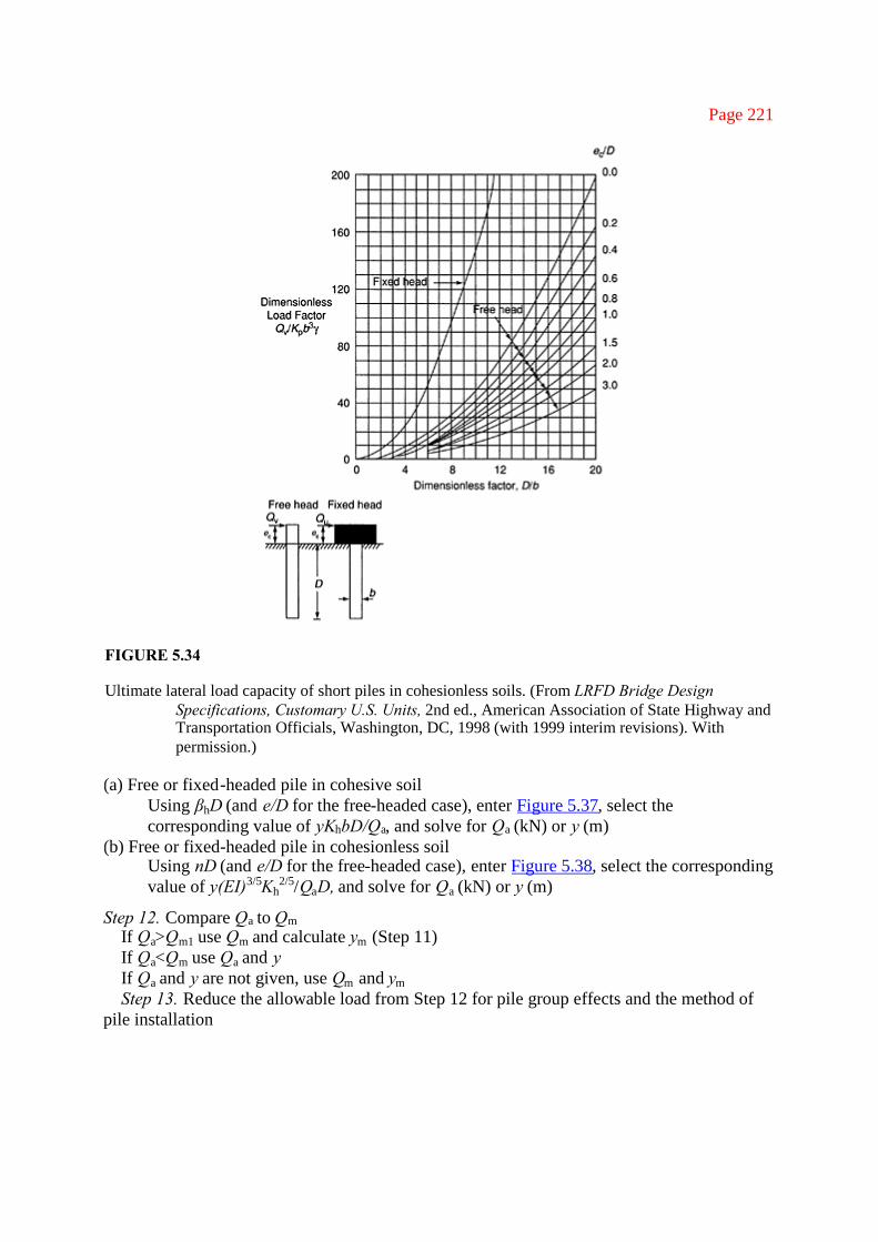
(c) Short free or fixed-headed pile in cohesionless soilUse D/b (and ec/D for the free-headed case), enter Figure 5.34, select the correspondingvalue of Qu/Kpb3γ, and solve for Qu (kN)
(d) Long free or fixed-headed pile in cohesionless soilUsing My/b4γKp (and ec/b for the free-headed case), enter Figure 5.35, select thecorresponding value of Qu/Kpb
3y, and solve for Qu (kN)

Page 220
FIGURE 5.33
Ultimate lateral load capacity of long piles in cohesive soils. (From LRFD Bridge DesignSpecifications, Customary U.S. Units, 2nd ed., American Association of State Highway andTransportation Officials, Washington, DC, 1998 (with 1999 interim revisions). Withpermission.)
(e) Intermediate free or fixed-headed pile in cohesionless soilCalculate Qu for both short pile (Step 9c) and long pile (Step 9d) and use the smallervalue.
Step 10: Calculate the maximum allowable working load for a single pile Qm. Calculate Qm,from the ultimate load Qu determined in step 9 as shown in Figure 5.36.
Step 11. Calculate the working load for a single pile, Qa to (kN)Calculate Qa corresponding to a given design deflection at the ground surface y (m) or the
deflection corresponding to a given design load (Figure 5.36). If Qa and y are not given,substitute the value of Qm (kN) from Step 10 for Qa in the following cases and solve for Ym(m):
Page 221
FIGURE 5.34
Ultimate lateral load capacity of short piles in cohesionless soils. (From LRFD Bridge DesignSpecifications, Customary U.S. Units, 2nd ed., American Association of State Highway andTransportation Officials, Washington, DC, 1998 (with 1999 interim revisions). Withpermission.)
(a) Free or fixed-headed pile in cohesive soilUsing βhD (and e/D for the free-headed case), enter Figure 5.37, select thecorresponding value of yKhbD/Qa, and solve for Qa (kN) or y (m)
(b) Free or fixed-headed pile in cohesionless soilUsing nD (and e/D for the free-headed case), enter Figure 5.38, select the correspondingvalue of y(EI)3/5Kh
2/5/QaD, and solve for Qa (kN) or y (m)
Step 12. Compare Qa to QmIf Qa>Qm1 use Qm and calculate ym (Step 11)If Qa<Qm use Qa and yIf Qa and y are not given, use Qm and ymStep 13. Reduce the allowable load from Step 12 for pile group effects and the method of
pile installation

Page 222
FIGURE 5.35
Ultimate lateral load capacity of long piles in cohesionless soils. (From LRFD Bridge DesignSpecifications, Customary U.S. Units, 2nd ed., American Association of State Highway andTransportation Officials, Washington, DC, 1998 (with 1999 interim revisions). Withpermission.)
FIGURE 5.36
Load deflection relationship used in determination of Brom’s maximum working load. (From LRFDBridge Design Specifications, Customary U.S. Units, 2nd ed., American Association ofState Highway and Transportation Officials, Washington, DC, 1998 (with 1999 interimrevisions). With permission.)

Page 223
FIGURE 5.37
Lateral deflection at ground surface of piles in cohesive soils. (From LRFD Bridge DesignSpecifications, Customary U.S. Units, 2nd ed., American Association of State Highway andTransportation Officials, Washington, DC, 1998 (with 1999 interim revisions). Withpermission.)
FIGURE 5.38

Lateral deflection at ground surface of piles in cohesionless soils. (From LRFD Bridge DesignSpecifications, Customary U.S. Units, 2nd ed., American Association of State Highway andTransportation Officials, Washington, DC, 1998 (with 1999 interim revisions). Withpermission.)

Page 224
TABLE 5.12
Group Reduction Factors
Z Reduction Factor8b 1.0
6b 0.8
4b 0.65
3b 0.5
Source: From LRFD Bridge DesignSpecifications, Customary U.S. Units, 2nd ed., American Association of State Highway and TransportationOfficials, Washington, DC, 1998 (with 1999 interim revisions). With permission.
FIGURE 5.39
Guide for Table 5.12.
(a) Group reduction factor determined by the center-to-center pile spacing, z, in the directionof load (Table 5.12 and Figure 5.39)
(b) Method of installation reduction factor
1. For driven piles use no reduction2. For jetted piles use 0.75 of the value from Step 13a
Step 14. Determine pile group lateral capacityThe total lateral load capacity of the pile group equals the adjusted allowable load per pile
from Step 13b times the number of piles. The deflection of the pile group is the value selectedin Step 12. It should be noted that no provision has been made to include the lateral resistanceoffered by the soil surrounding an embedded pile cap.

Page 225
Example 5.8
Drill shaft designYou have been engaged as a foundation engineering consultant to design a drilled shaft for abuilding. Geotechnical engineers have recommended a drilled shaft or a group of piles. Thevalue engineering analysis has indicated the drill shaft will be the most costeffective solution.The structural engineer analyzing the building has given the following loading data that needto be transferred to the ground:
Working DL=520 kipsLL=314 kipsWorking DL moment=2,550 kip-ftLL moment=1,120 kip-ftWorking horizontal load=195 kip
The attached borehole data (Figure 5.40) were given by the geotechnical engineer. You arerequired to design a single reinforced concrete drill shaft with concrete and fy=60 ksi.
FIGURE 5.40
Soil profile for Example 5.8.

Page 226
Drill shaftGiven:
Neglect resistance from the top layer of 5 ft. We will consider the second layer and assumethe rock layer is the cohesive layer to determine the length of drilled shaft:
Skin friction from stiff clay (second layer)
End bearing from bed shocketDia=6.0 diaQT=20×28.27=565 kips
Therefore, take drill shaft at least 1 diameter depth into the rock, say 6 ft. Now check forlateral loads
From the top of stiff clay

Page 227
SolutionFollowing the step-by-step procedure:Step 1. Soil type within (4×D=) 24 ft depth = cohesive stiff clayStep 2. Computation of coefficient of horizontal subgrade reaction, Kh, with the critical
depth
Concrete drilled shaft from Table 5.10
where qu=224 kPa
Step 3. Adjust Kh for loading and soil conditions for stiff clays
Step 4. Determine shaft parameters (Figure 5.41)
(a) Modulus of elasticity

Page 228
FIGURE 5.41
Shaft section with reinforcement layout: (a) schematic; (b) actual design
(b) Moment of inertia
=0.125×0.03113×1.62
=0.010 m4
Ie=Ig+(n−1)Ise=0.549+(g−1) (0.010) m4
Ie=0.619 m4
(c) Section modulus
S=0.677 m3
= 677×10−3 m3

Page 229
(d) Yield stress of drilled shaft
Concrete=4,000 psi=27.58 MPa
(e) Embedded shaft length
D=23 ft=7.02 m
(f) Diameter=b=1.8287 m
(g) Eccentricity of applied load ec
ec=23.82 ft=7.265 m
(h) Resisting moment of pile My
Step 5. Determineβh for cohesive soils
Step 6. Determine the dimensionless length factor
βhD=0.091×7.265=0.66
Step 7. Determine if the shaft is long or short (cohesive soil)
βhD>2.25 (long)βhD<2.25 (short)
Since βhD=0.66, it is a short drilled shaftStep 8. Determine the soil parametersRankine passive pressure coefficient cohesionless soilSince the soil that is of concrete, this design is a cohesive one

Or Cu=2.35 ksf

Page 230
Step 9. Determine the dimensionless factor D/b
This is a fixed head (the building column is fixed at base). From Figure 5.32 (for cohesivesoil),
Qu/cub2=20.0 (dimensionless b factor)
Qu=b2cu(20)=62×2.35×20= 1692 kips (horizontal force)
Step 10. Maximum allowable working load=1692/2.5=676.8 kips which is>195 kipsStep 11. Calculate the deflection yDimensionless factor βhD=0.66From Figure 5.37 (lateral deflection at ground surface for cohesive soil),Dimensionless factor (fixed head)Replace Qa · Qm by the applied load
Shaft Design (Figure 5.42 and Figure 5.43; Table 5.13)

Page 231
FIGURE 5.42
Drilled shaft column interaction.
FIGURE 5.43
Rebar details of drilled shaft.

Page 232
TABLE 5.13
Strength of Reinforced Column Sections from ACI Column Chart
ρg Pf QPn/4g (ksi) QMn/Agh (ksi) QMn (k.ft)0.012 2 2.60 10586 0.181 4422
0.012 5 1.318 5366 0.392 9576
0.012 6 0.400 1628.4 0.317 7743
0.012 7 0 0 0.254 6205
Source: LRFD Bridge Design Specifications, Customary U.S. Units, 2nd edn, American Association of StateHighway and Transportation Officials, Washington, DC, 1998 (with 1999 interim revisions). With permission.
Example 5.10: Additional footing design example (rigid footing)Machine Foundation ProblemAs a foundation engineer you have been asked to design a machine foundation footing for a
bakery mixer. The mixer loads are given below. The rear legs are subjected to additionalshock load of 16 kips/ft2. All four legs are identical with 100 in.2 area. Given that fc=4 ksi andfy=60 ksi, design the footing. Maximum allowable bearing pressure=2.5 ksf (Figure 5.44–Figure 5.47).
Data from the manufacturer or mixer:
Net weight/leg DL=10 kips/ft2
Floor load, FL=10 kips/ft2
Shock load, SL=16 kips/ft2
FIGURE 5.44
Illustration for Example 5.10 (plan).

FIGURE 5.45
Illustration for Example 5.10 (elevation).

Page 233
FIGURE 5.46
Bending moment diagram for Example 5.10.
FIGURE 5.47
Reinforcement details (Example 5.10).
Load on rear legs=36 kips/ft2
Area of a rear leg=100 in.2
Area of a leg=0.69 ft2
Design load=1.6(FL+SL+DL) for rear legs. Also note that a load factor of 1.6 is usedP=40.00 kipsBy considering the case with rear leg loading, we will design the footing for this load case:Total load/rear legs=2P=80 kipsWidth of the footing=4.00 ft (4 ft strip) for worse conditionLength of the footing=10.00 ftDepth=1.50 ftd=13.50 in.Area=40.00 ft2, assume 3-in. coverPressure under the footing=2.225 ksf < 2.5 ksf. OK
References
1. American Concrete Institute: ACI-318 Building Code Requirements for Reinforced Concrete andCommentary.
2. ACI 209 publication on shrinkage, Creep and Thermal Movements.3. Notes on ACI 318–95 Building Code Requirements for Structural Concrete with Design Applica-

Page 234
tion by Portland Cement Association.4. AASHTO LRFD Bridge Design Specifications.5. Florida Department of Transportation: Bridge Design Guidelines.6. FHWA, 1998, Design and Construction of Driven Pile Foundations, Workshop Manual, vol. I,
Publication Number FHWA HI-97–013, Revised, November.