Chapter 5 Steady-State Sinusoidal Analysis Notes/Chapter 05.pdf · 14.14 14.14 8.660 5 20 45 10 30...
73
ELECTRICAL ENGINEERING Principles and Applications SE OND EDITION Chapter 5 Steady-State Sinusoidal Analysis Chapter 5 Steady-State Sinusoidal Analysis 1. Identify the frequency, angular frequency, peak value, rms value, and phase of a sinusoidal signal. 2. Solve steady-state ac circuits using phasors and complex impedances.
Transcript of Chapter 5 Steady-State Sinusoidal Analysis Notes/Chapter 05.pdf · 14.14 14.14 8.660 5 20 45 10 30...
ELECTRICAL
ENGINEERINGPrinciples and
Applications
SE OND EDITION
Chapter 5Steady-State Sinusoidal Analysis
Chapter 5Steady-State Sinusoidal Analysis
1. Identify the frequency, angular frequency, peak value, rms value, and phase of a sinusoidal signal.
2. Solve steady-state ac circuits using phasors and complex impedances.
ELECTRICAL
ENGINEERINGPrinciples and
Applications
SE OND EDITION
Chapter 5Steady-State Sinusoidal Analysis
4. Find Thévenin and Norton equivalent circuits. Lightly.
5. Determine load impedances for maximum power transfer.
3. Compute power for steady-state ac circuits.
ELECTRICAL
ENGINEERINGPrinciples and
Applications
SE OND EDITION
Chapter 5Steady-State Sinusoidal Analysis
ELECTRICAL
ENGINEERINGPrinciples and
Applications
SE OND EDITION
Chapter 5Steady-State Sinusoidal Analysis
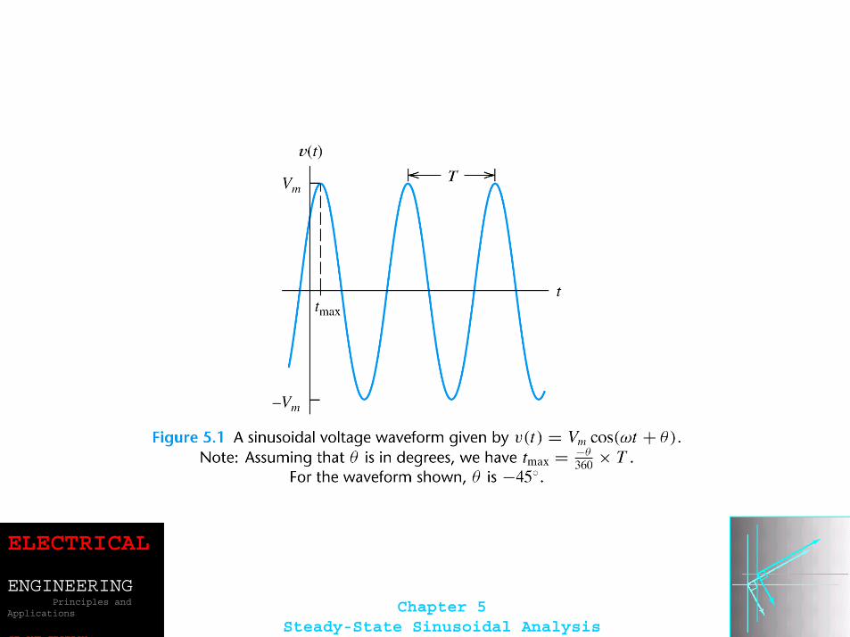
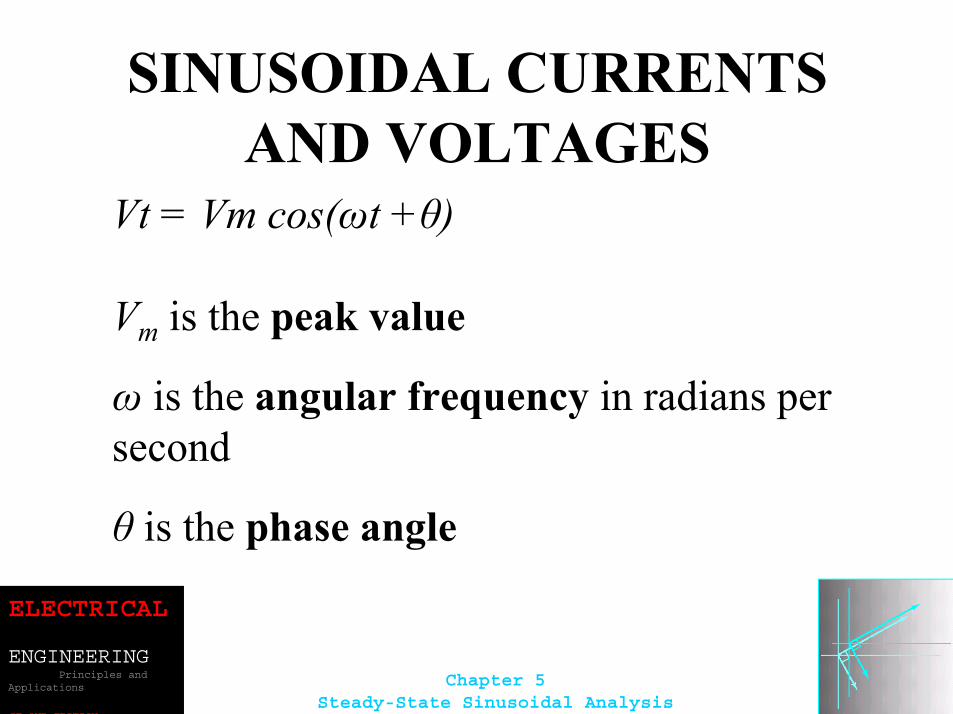
SINUSOIDAL CURRENTS AND VOLTAGES
Vt = Vm cos(ωt +θ)
Vm is the peak value
ω is the angular frequency in radians per second
θ is the phase angle
ELECTRICAL
ENGINEERINGPrinciples and
Applications
SE OND EDITION
Chapter 5Steady-State Sinusoidal Analysis
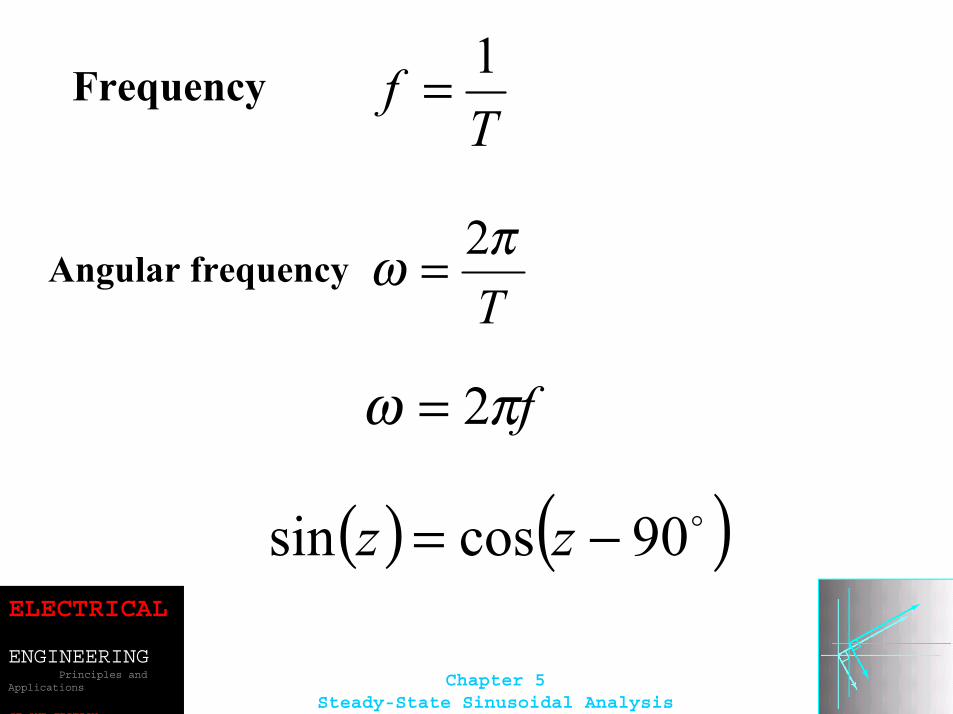
Tπω 2=
fπω 2=
( ) ( )o90cossin −= zz
Frequency T
f 1=
Angular frequency
ELECTRICAL
ENGINEERINGPrinciples and
Applications
SE OND EDITION
Chapter 5Steady-State Sinusoidal Analysis
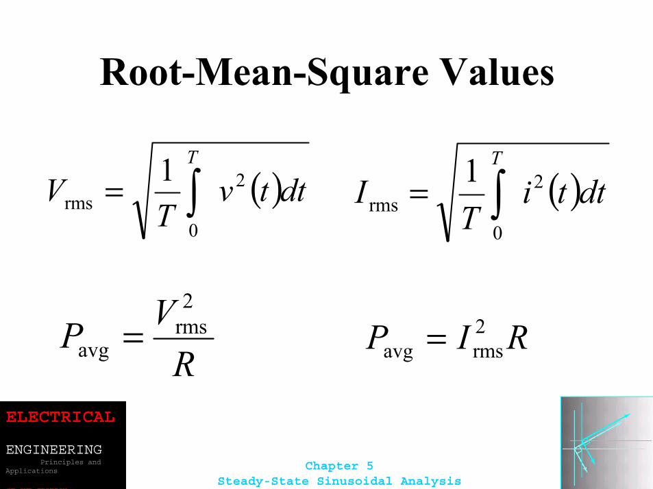
Root-Mean-Square Values
( )dttvT
VT
2
0rms
1∫=
RVP
2rms
avg =
( )dttiT
IT
2
0rms
1∫=
RIP 2rmsavg =
ELECTRICAL
ENGINEERINGPrinciples and
Applications
SE OND EDITION
Chapter 5Steady-State Sinusoidal Analysis
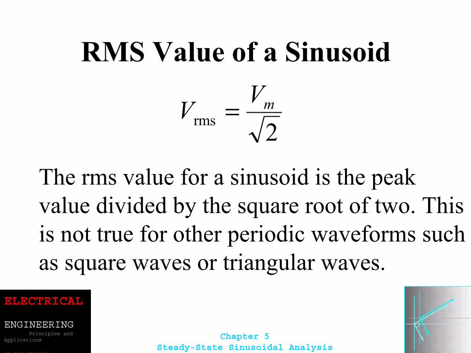
RMS Value of a Sinusoid
2rmsmVV =
The rms value for a sinusoid is the peak value divided by the square root of two. This is not true for other periodic waveforms such as square waves or triangular waves.
ELECTRICAL
ENGINEERINGPrinciples and
Applications
SE OND EDITION
Chapter 5Steady-State Sinusoidal Analysis
ELECTRICAL
ENGINEERINGPrinciples and
Applications
SE OND EDITION
Chapter 5Steady-State Sinusoidal Analysis
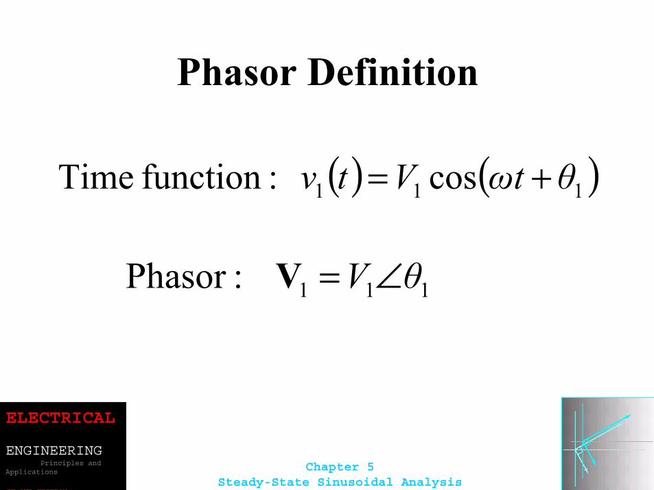
Phasor Definition
( ) ( )111 cos :function Time θtωVtv +=
111 :Phasor θV ∠=V
ELECTRICAL
ENGINEERINGPrinciples and
Applications
SE OND EDITION
Chapter 5Steady-State Sinusoidal Analysis
Adding Sinusoids Using Phasors
Step 1: Determine the phasor for each term.
Step 2: Add the phasors using complex arithmetic.
Step 3: Convert the sum to polar form.
Step 4: Write the result as a time function.
ELECTRICAL
ENGINEERINGPrinciples and
Applications
SE OND EDITION
Chapter 5Steady-State Sinusoidal Analysis
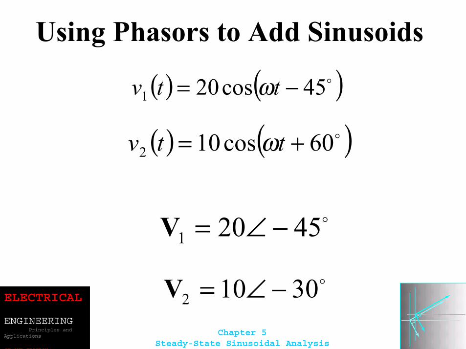
Using Phasors to Add Sinusoids
( ) ( )o45cos201 −= ttv ω
( ) ( )o60cos102 += ttv ω
o45201 −∠=V
o30102 −∠=V
ELECTRICAL
ENGINEERINGPrinciples and
Applications
SE OND EDITION
Chapter 5Steady-State Sinusoidal Analysis
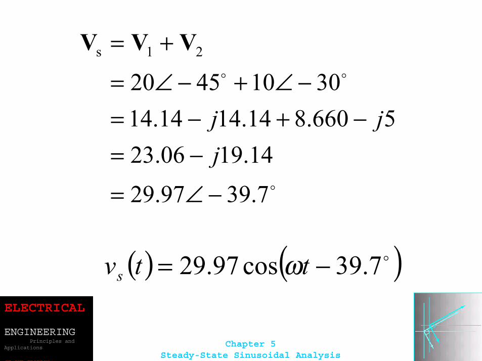
o
oo
7.3997.2914.1906.23
5660.814.1414.1430104520
21s
−∠=−=
−+−=−∠+−∠=
+=
jjj
VVV
( ) ( )o7.39cos97.29 −= ttvs ω
ELECTRICAL
ENGINEERINGPrinciples and
Applications
SE OND EDITION
Chapter 5Steady-State Sinusoidal Analysis
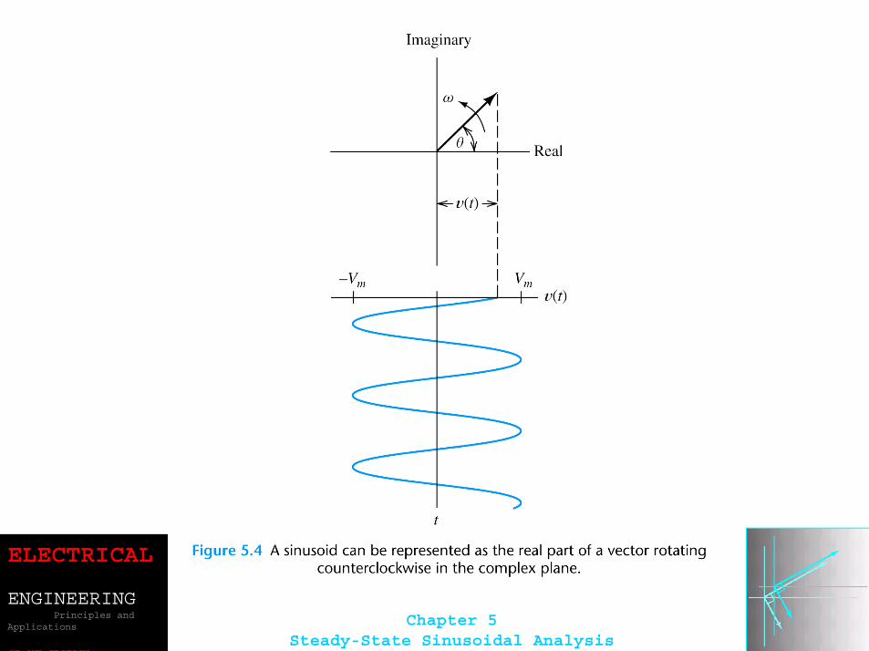
Sinusoids can be visualized as the real-axis projection of vectors rotating in the complex plane. The phasor for a sinusoid is a snapshot of the corresponding rotating vector at t = 0.
ELECTRICAL
ENGINEERINGPrinciples and
Applications
SE OND EDITION
Chapter 5Steady-State Sinusoidal Analysis
ELECTRICAL
ENGINEERINGPrinciples and
Applications
SE OND EDITION
Chapter 5Steady-State Sinusoidal Analysis
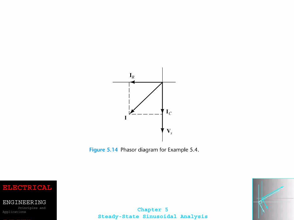
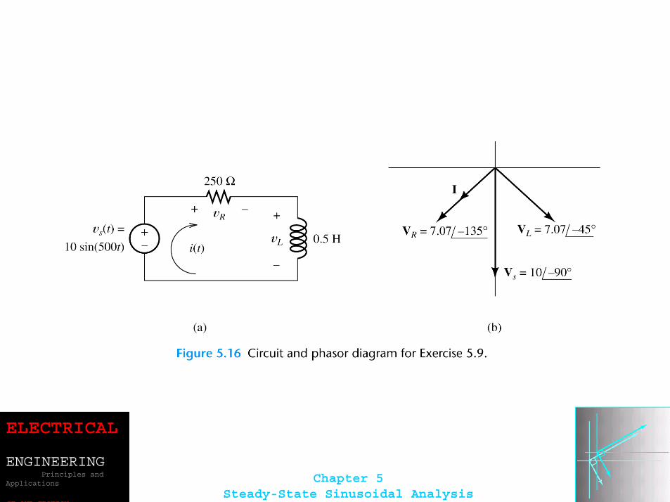
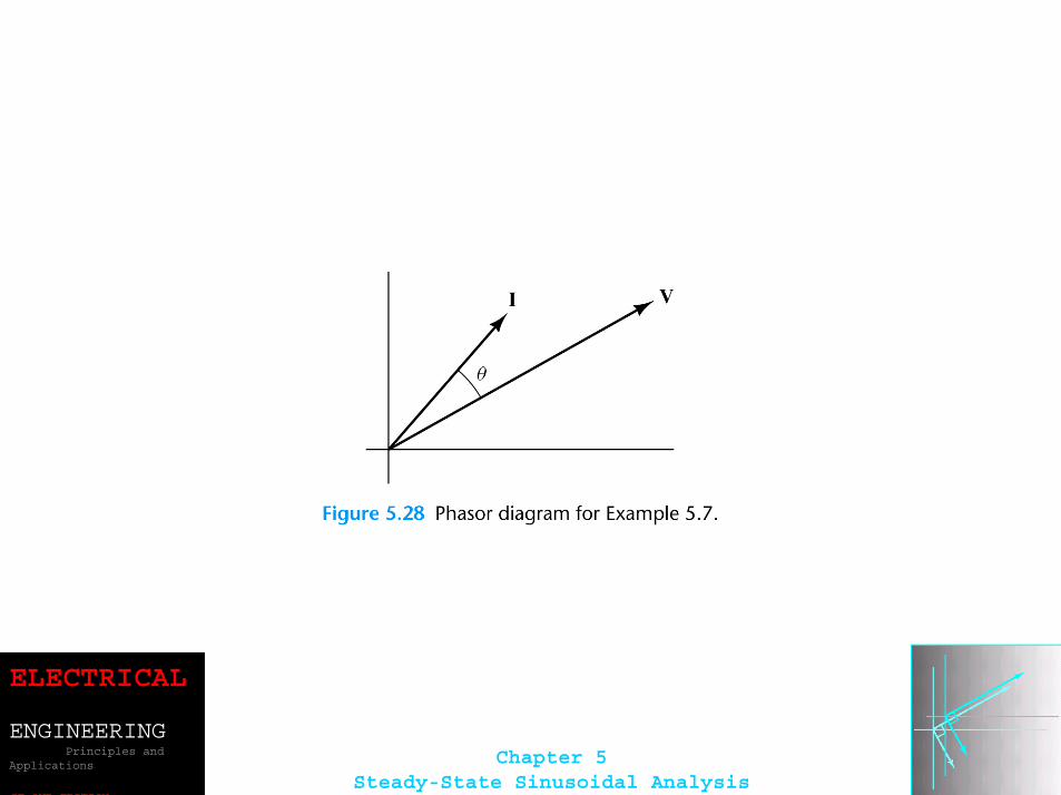
Phase Relationships
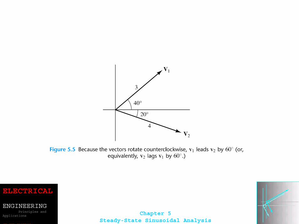
To determine phase relationships from a phasor diagram, consider the phasors to rotate counterclockwise. Then when standing at afixed point, if V1 arrives first followed by V2 after a rotation of θ , we say that V1 leads V2 by θ . Alternatively, we could say that V2 lags V1 by θ . (Usually, we take θ as the smaller angle between the two phasors.)
ELECTRICAL
ENGINEERINGPrinciples and
Applications
SE OND EDITION
Chapter 5Steady-State Sinusoidal Analysis
ELECTRICAL
ENGINEERINGPrinciples and
Applications
SE OND EDITION
Chapter 5Steady-State Sinusoidal Analysis
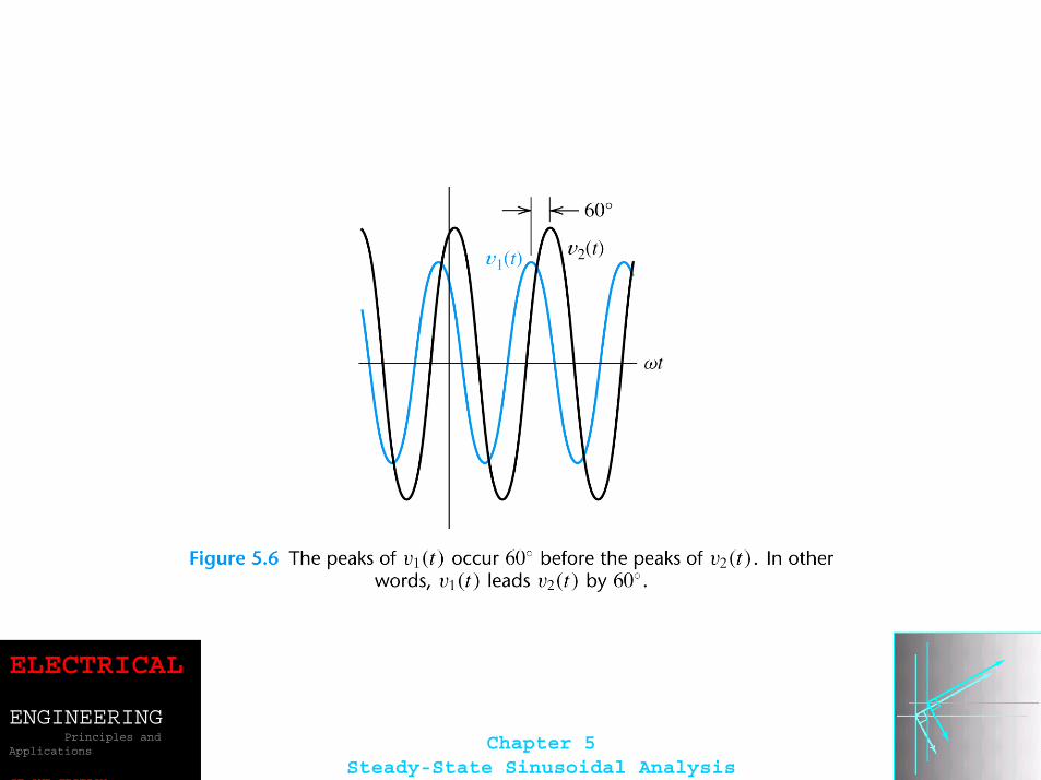
To determine phase relationships between sinusoids from their plots versus time, find the shortest time interval tp between positive peaks of the two waveforms. Then, the phase angle isθ = (tp/T )× 360°. If the peak of v1(t) occurs first, we say that v1(t) leads v2(t) or that v2(t) lags v1(t).
ELECTRICAL
ENGINEERINGPrinciples and
Applications
SE OND EDITION
Chapter 5Steady-State Sinusoidal Analysis
ELECTRICAL
ENGINEERINGPrinciples and
Applications
SE OND EDITION
Chapter 5Steady-State Sinusoidal Analysis
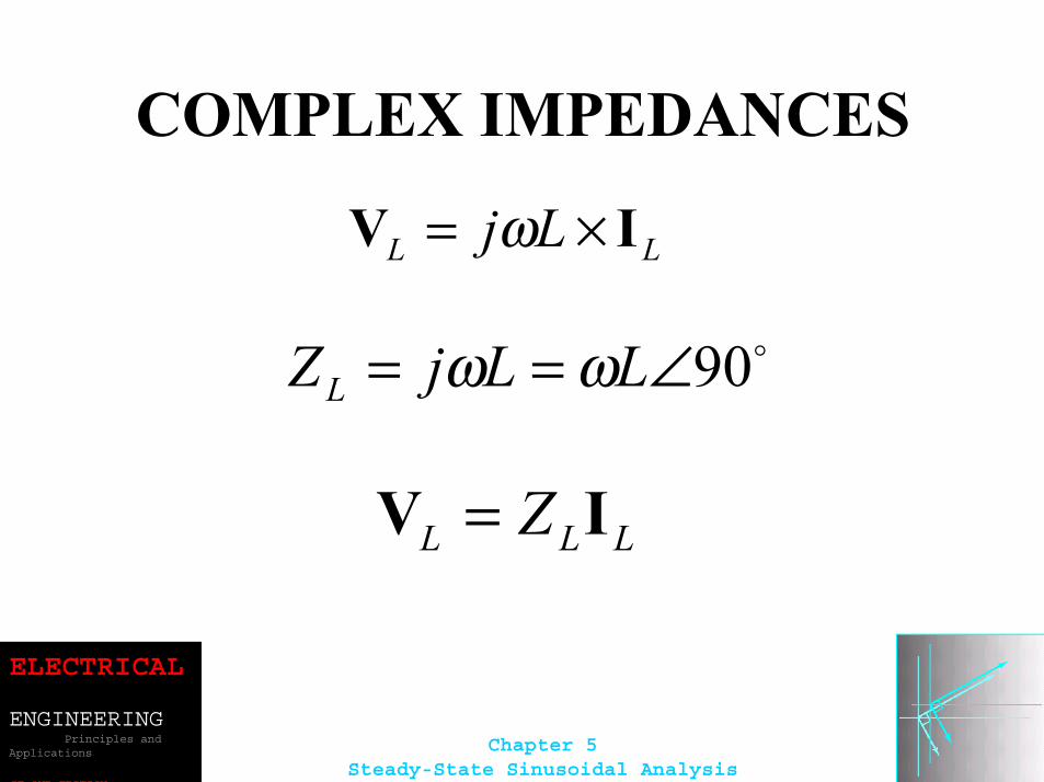
COMPLEX IMPEDANCES
LL Lj IV ×= ω
o90∠== LLjZL ωω
LLL Z IV =
ELECTRICAL
ENGINEERINGPrinciples and
Applications
SE OND EDITION
Chapter 5Steady-State Sinusoidal Analysis
ELECTRICAL
ENGINEERINGPrinciples and
Applications
SE OND EDITION
Chapter 5Steady-State Sinusoidal Analysis
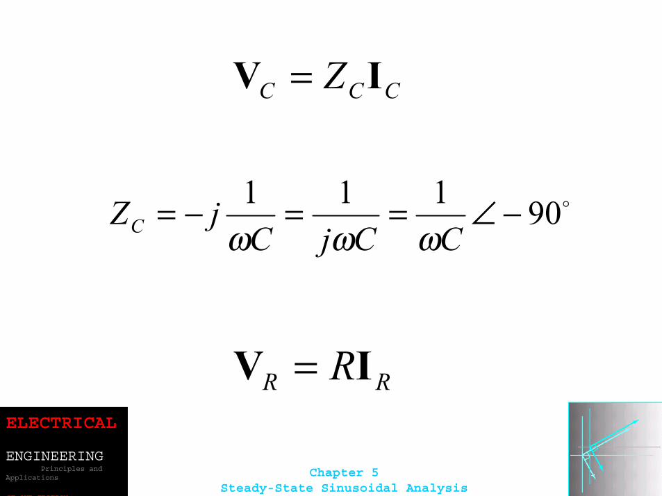
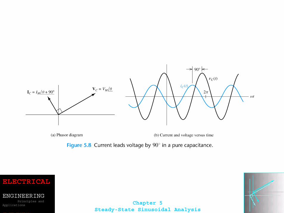
CCC Z IV =
o90111 −∠==−=CCjC
jZC ωωω
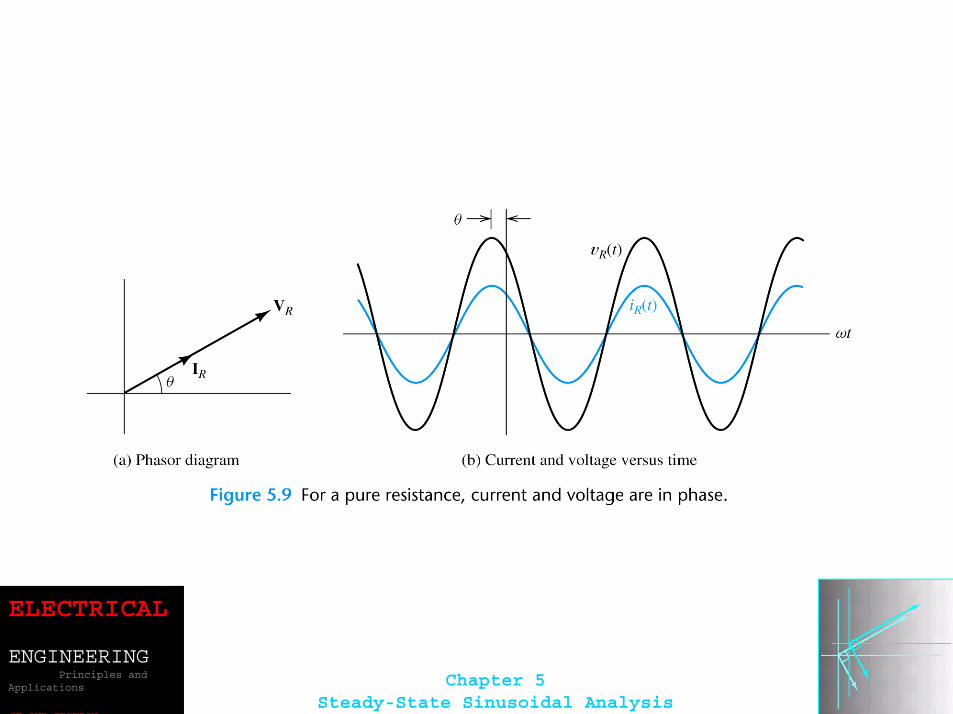
RR RIV =
ELECTRICAL
ENGINEERINGPrinciples and
Applications
SE OND EDITION
Chapter 5Steady-State Sinusoidal Analysis
ELECTRICAL
ENGINEERINGPrinciples and
Applications
SE OND EDITION
Chapter 5Steady-State Sinusoidal Analysis
ELECTRICAL
ENGINEERINGPrinciples and
Applications
SE OND EDITION
Chapter 5Steady-State Sinusoidal Analysis
ELECTRICAL
ENGINEERINGPrinciples and
Applications
SE OND EDITION
Chapter 5Steady-State Sinusoidal Analysis
Kirchhoff’s Laws in Phasor Form
We can apply KVL directly to phasors. The sum of the phasor voltages equals zero for any closed path.
The sum of the phasor currents entering a node must equal the sum of the phasor currents leaving.
ELECTRICAL
ENGINEERINGPrinciples and
Applications
SE OND EDITION
Chapter 5Steady-State Sinusoidal Analysis
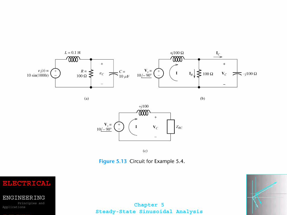
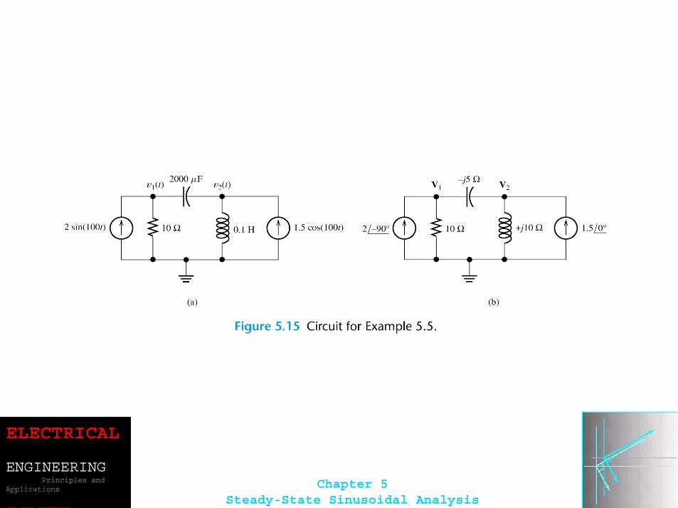
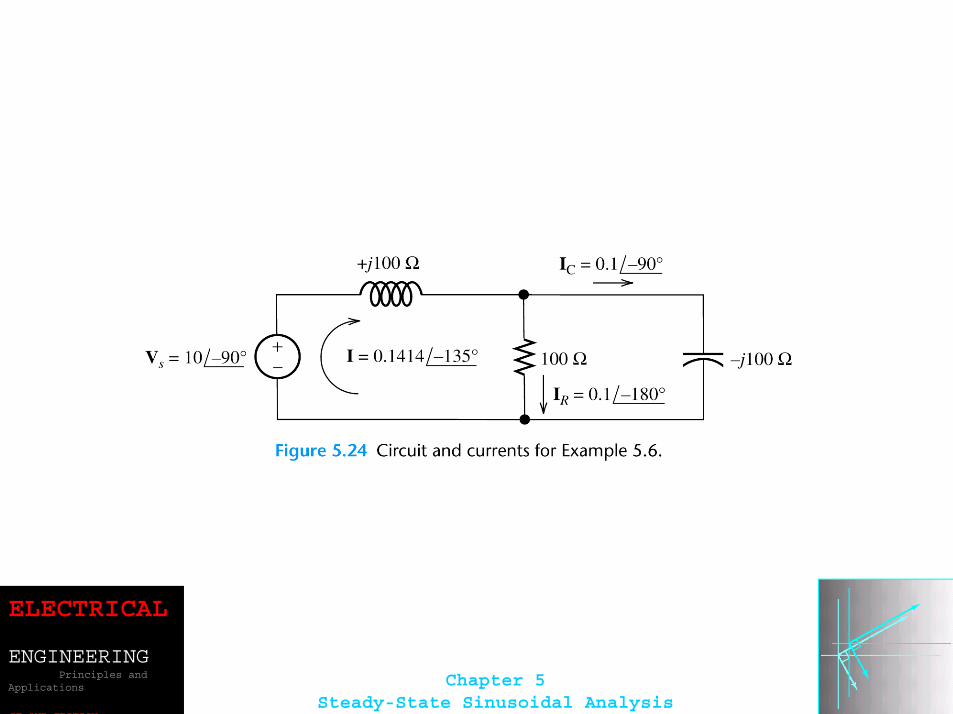
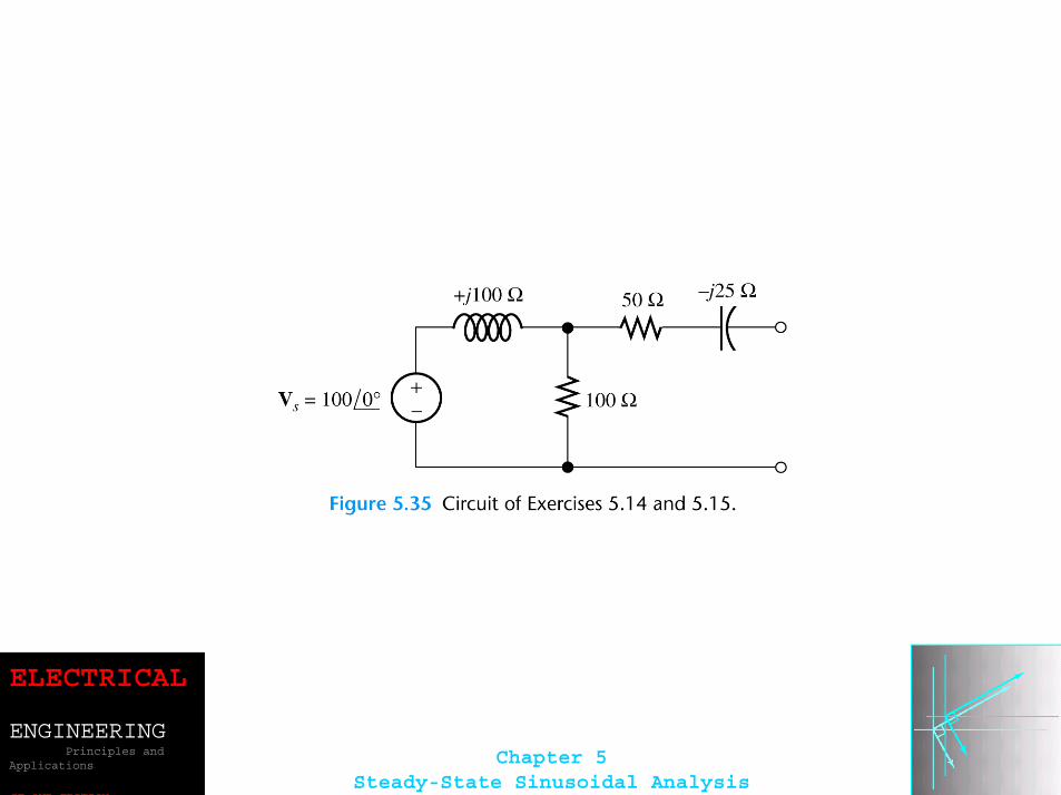
Circuit Analysis Using Phasors and Impedances
1. Replace the time descriptions of the voltage and current sources with the corresponding phasors. (All of the sources must have the same frequency.)
ELECTRICAL
ENGINEERINGPrinciples and
Applications
SE OND EDITION
Chapter 5Steady-State Sinusoidal Analysis
2. Replace inductances by their complex impedances ZL = jωL. Replacecapacitances by their complex impedances ZC = 1/(jωC). Resistances have impedances equal to their resistances.
3. Analyze the circuit using any of the techniques studied earlier in Chapter 2, performing the calculations with complex arithmetic.
ELECTRICAL
ENGINEERINGPrinciples and
Applications
SE OND EDITION
Chapter 5Steady-State Sinusoidal Analysis
ELECTRICAL
ENGINEERINGPrinciples and
Applications
SE OND EDITION
Chapter 5Steady-State Sinusoidal Analysis
ELECTRICAL
ENGINEERINGPrinciples and
Applications
SE OND EDITION
Chapter 5Steady-State Sinusoidal Analysis
ELECTRICAL
ENGINEERINGPrinciples and
Applications
SE OND EDITION
Chapter 5Steady-State Sinusoidal Analysis
ELECTRICAL
ENGINEERINGPrinciples and
Applications
SE OND EDITION
Chapter 5Steady-State Sinusoidal Analysis
ELECTRICAL
ENGINEERINGPrinciples and
Applications
SE OND EDITION
Chapter 5Steady-State Sinusoidal Analysis
ELECTRICAL
ENGINEERINGPrinciples and
Applications
SE OND EDITION
Chapter 5Steady-State Sinusoidal Analysis
ELECTRICAL
ENGINEERINGPrinciples and
Applications
SE OND EDITION
Chapter 5Steady-State Sinusoidal Analysis
ELECTRICAL
ENGINEERINGPrinciples and
Applications
SE OND EDITION
Chapter 5Steady-State Sinusoidal Analysis
ELECTRICAL
ENGINEERINGPrinciples and
Applications
SE OND EDITION
Chapter 5Steady-State Sinusoidal Analysis
ELECTRICAL
ENGINEERINGPrinciples and
Applications
SE OND EDITION
Chapter 5Steady-State Sinusoidal Analysis
ELECTRICAL
ENGINEERINGPrinciples and
Applications
SE OND EDITION
Chapter 5Steady-State Sinusoidal Analysis
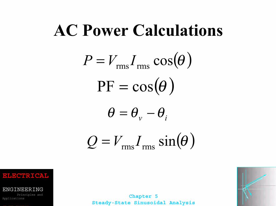
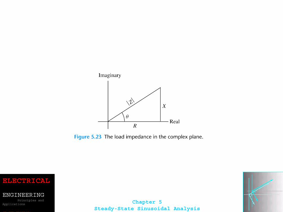
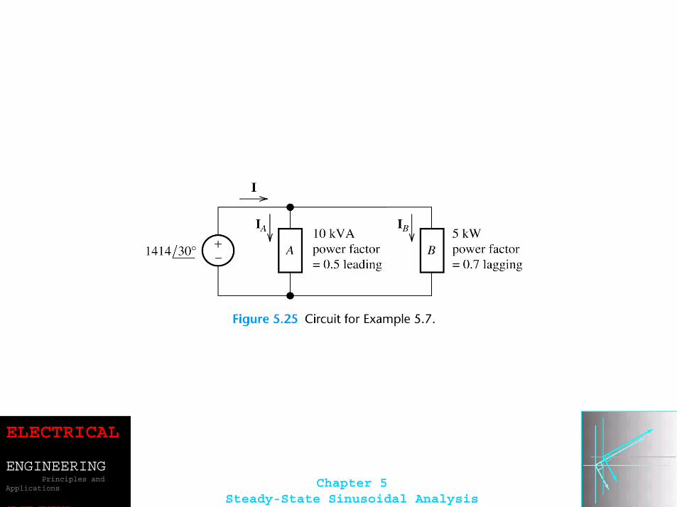
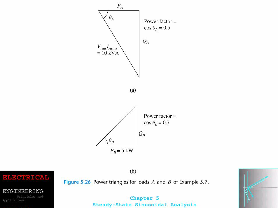
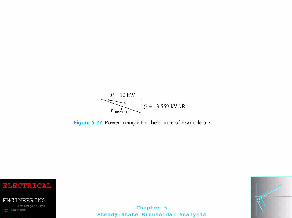
AC Power Calculations
( )θcosrmsrms IVP =
( )θcosPF =
iv θθθ −=
( )θsinrmsrmsIVQ =
ELECTRICAL
ENGINEERINGPrinciples and
Applications
SE OND EDITION
Chapter 5Steady-State Sinusoidal Analysis
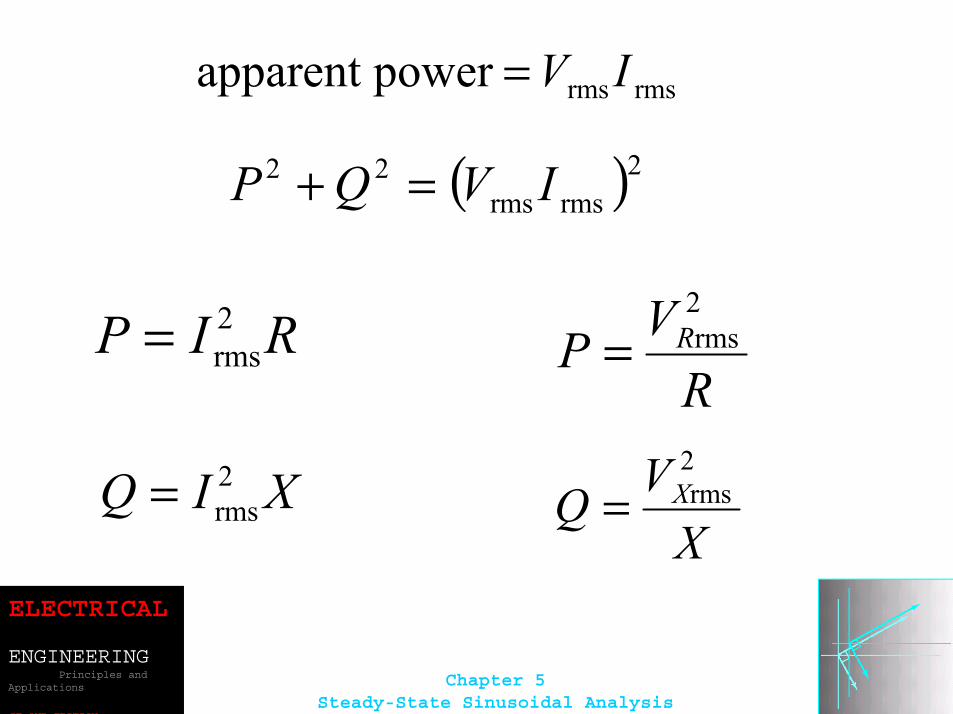
rmsrmspower apparent IV=
( )2rmsrms
22 IVQP =+
RIP 2rms=
XIQ 2rms=
RVP R
2rms=
XVQ X
2rms=
ELECTRICAL
ENGINEERINGPrinciples and
Applications
SE OND EDITION
Chapter 5Steady-State Sinusoidal Analysis
ELECTRICAL
ENGINEERINGPrinciples and
Applications
SE OND EDITION
Chapter 5Steady-State Sinusoidal Analysis
ELECTRICAL
ENGINEERINGPrinciples and
Applications
SE OND EDITION
Chapter 5Steady-State Sinusoidal Analysis
ELECTRICAL
ENGINEERINGPrinciples and
Applications
SE OND EDITION
Chapter 5Steady-State Sinusoidal Analysis
ELECTRICAL
ENGINEERINGPrinciples and
Applications
SE OND EDITION
Chapter 5Steady-State Sinusoidal Analysis
ELECTRICAL
ENGINEERINGPrinciples and
Applications
SE OND EDITION
Chapter 5Steady-State Sinusoidal Analysis
ELECTRICAL
ENGINEERINGPrinciples and
Applications
SE OND EDITION
Chapter 5Steady-State Sinusoidal Analysis
ELECTRICAL
ENGINEERINGPrinciples and
Applications
SE OND EDITION
Chapter 5Steady-State Sinusoidal Analysis
ELECTRICAL
ENGINEERINGPrinciples and
Applications
SE OND EDITION
Chapter 5Steady-State Sinusoidal Analysis
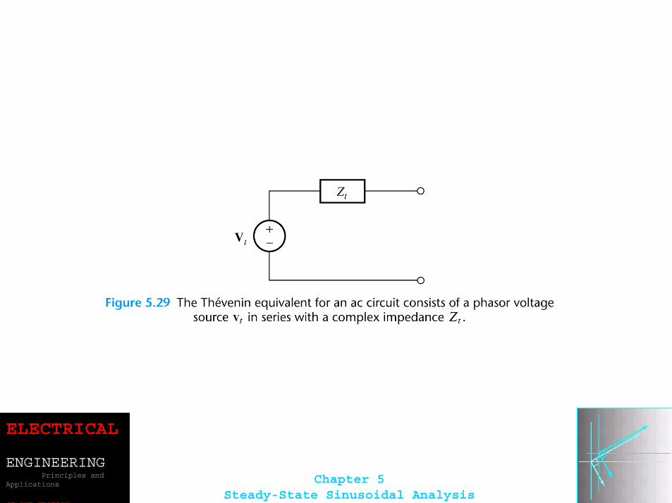
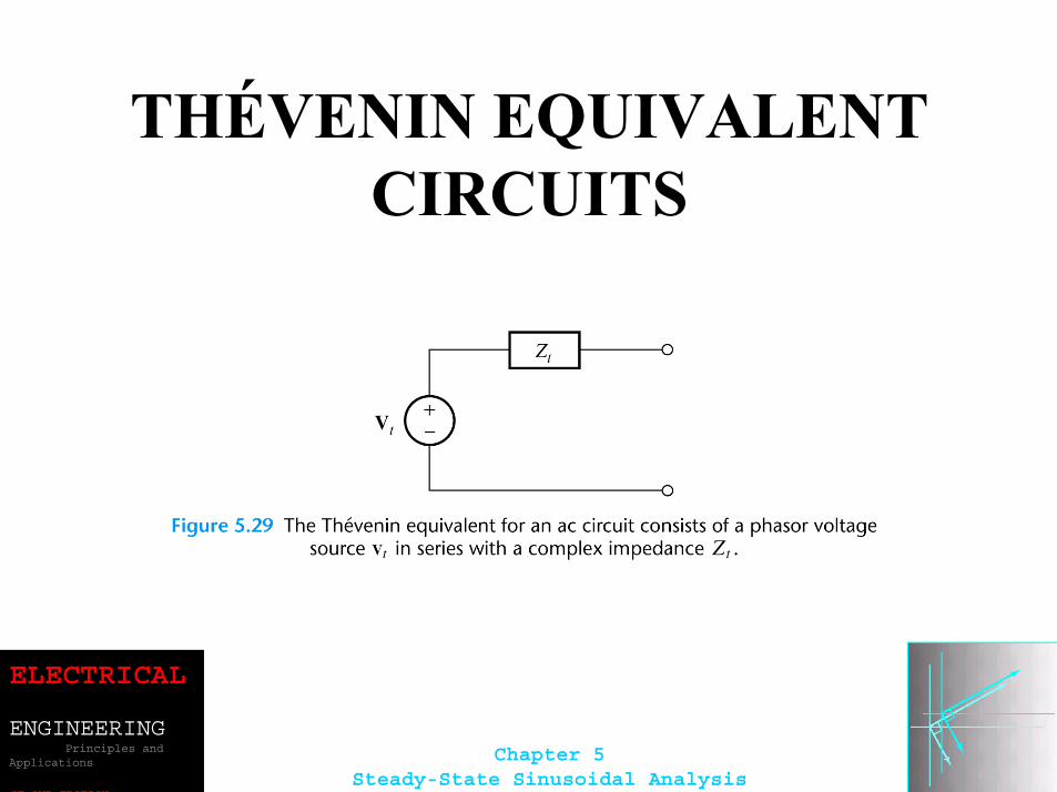
THÉVENIN EQUIVALENT CIRCUITS
ELECTRICAL
ENGINEERINGPrinciples and
Applications
SE OND EDITION
Chapter 5Steady-State Sinusoidal Analysis
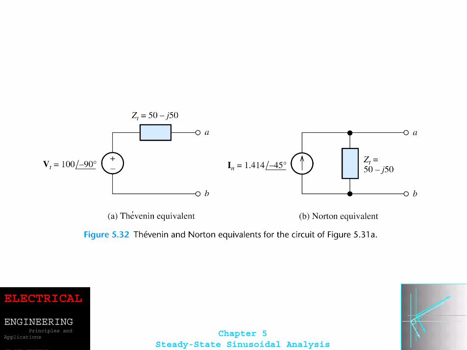
The Thévenin voltage is equal to the open-circuit phasor voltage of the original circuit.
ocVV =t
We can find the Thévenin impedance by zeroing the independent sources and determining the impedance looking into the circuit terminals.
ELECTRICAL
ENGINEERINGPrinciples and
Applications
SE OND EDITION
Chapter 5Steady-State Sinusoidal Analysis
The Thévenin impedance equals the open-circuit voltage divided by the short-circuit current.
scsc
oc
IV
IV t
tZ ==
scII =n
ELECTRICAL
ENGINEERINGPrinciples and
Applications
SE OND EDITION
Chapter 5Steady-State Sinusoidal Analysis
ELECTRICAL
ENGINEERINGPrinciples and
Applications
SE OND EDITION
Chapter 5Steady-State Sinusoidal Analysis
ELECTRICAL
ENGINEERINGPrinciples and
Applications
SE OND EDITION
Chapter 5Steady-State Sinusoidal Analysis
ELECTRICAL
ENGINEERINGPrinciples and
Applications
SE OND EDITION
Chapter 5Steady-State Sinusoidal Analysis
ELECTRICAL
ENGINEERINGPrinciples and
Applications
SE OND EDITION
Chapter 5Steady-State Sinusoidal Analysis
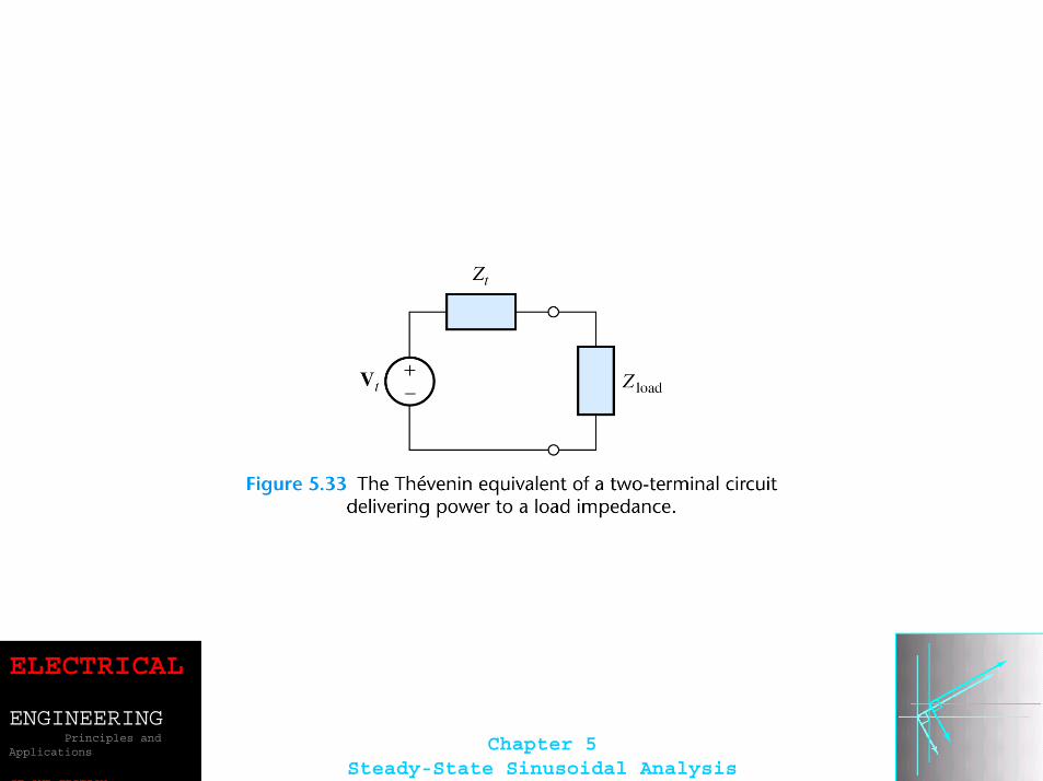
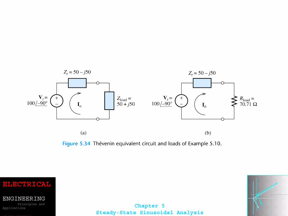
Maximum Power TransferIf the load can take on any complex value, maximum power transfer is attained for a load impedance equal to the complex conjugate of the Thévenin impedance.
If the load is required to be a pure resistance, maximum power transfer is attained for a load resistance equal to the magnitude of the Thévenin impedance.
ELECTRICAL
ENGINEERINGPrinciples and
Applications
SE OND EDITION
Chapter 5Steady-State Sinusoidal Analysis
ELECTRICAL
ENGINEERINGPrinciples and
Applications
SE OND EDITION
Chapter 5Steady-State Sinusoidal Analysis
ELECTRICAL
ENGINEERINGPrinciples and
Applications
SE OND EDITION
Chapter 5Steady-State Sinusoidal Analysis
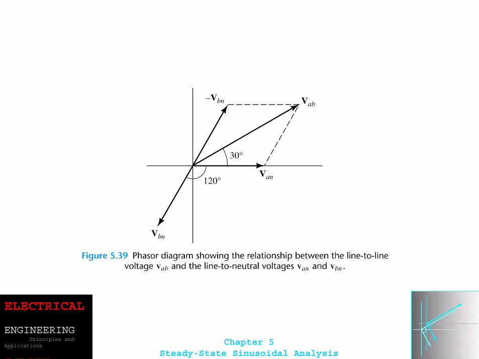
BALANCED THREE-PHASE CIRCUITS
Much of the power used by business and industry is supplied by three-phase distribution systems. Plant engineers need to be familiar with three-phase power.
ELECTRICAL
ENGINEERINGPrinciples and
Applications
SE OND EDITION
Chapter 5Steady-State Sinusoidal Analysis
ELECTRICAL
ENGINEERINGPrinciples and
Applications
SE OND EDITION
Chapter 5Steady-State Sinusoidal Analysis
Phase Sequence
Three-phase sources can have either a positive or negative phase sequence.
The direction of rotation of certain three-phase motors can be reversed by changing the phase sequence.
ELECTRICAL
ENGINEERINGPrinciples and
Applications
SE OND EDITION
Chapter 5Steady-State Sinusoidal Analysis
ELECTRICAL
ENGINEERINGPrinciples and
Applications
SE OND EDITION
Chapter 5Steady-State Sinusoidal Analysis
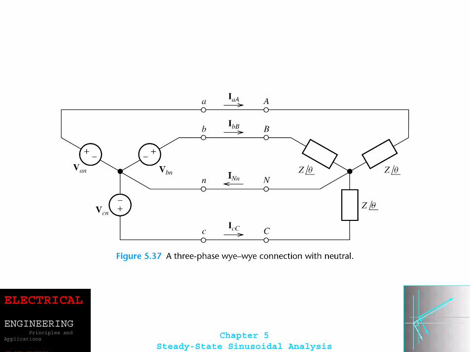
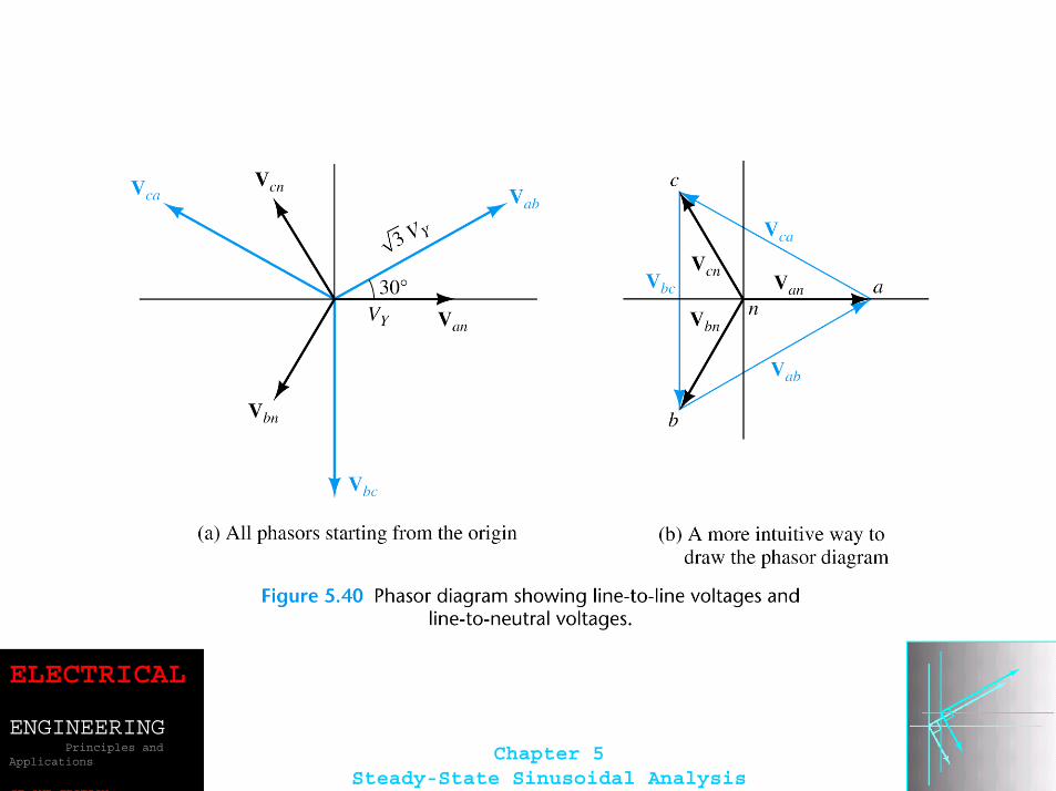
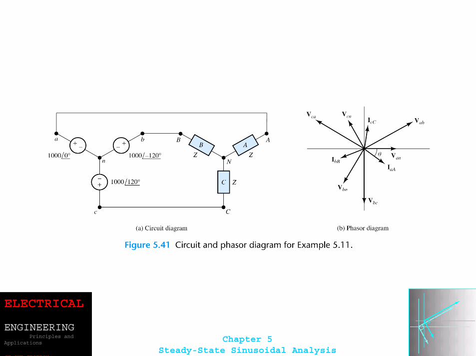
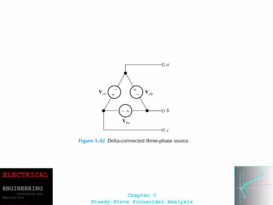
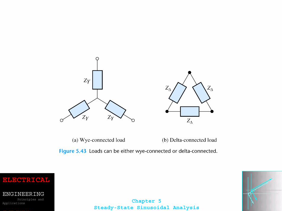
Wye–Wye ConnectionThree-phase sources and loads can be connected either in a wye configuration or in a delta configuration.
The key to understanding the various three-phaseconfigurations is a careful examination of the wye–wye circuit.
ELECTRICAL
ENGINEERINGPrinciples and
Applications
SE OND EDITION
Chapter 5Steady-State Sinusoidal Analysis
ELECTRICAL
ENGINEERINGPrinciples and
Applications
SE OND EDITION
Chapter 5Steady-State Sinusoidal Analysis
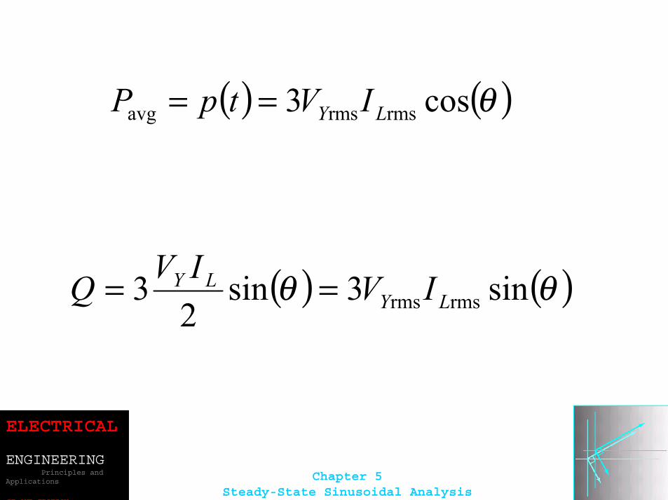
( ) ( )θcos3 rmsrmsavg LY IVtpP ==
( ) ( )θθ sin3sin2
3 rmsrms LYLY IVIVQ ==
ELECTRICAL
ENGINEERINGPrinciples and
Applications
SE OND EDITION
Chapter 5Steady-State Sinusoidal Analysis
ELECTRICAL
ENGINEERINGPrinciples and
Applications
SE OND EDITION
Chapter 5Steady-State Sinusoidal Analysis
ELECTRICAL
ENGINEERINGPrinciples and
Applications
SE OND EDITION
Chapter 5Steady-State Sinusoidal Analysis
ELECTRICAL
ENGINEERINGPrinciples and
Applications
SE OND EDITION
Chapter 5Steady-State Sinusoidal Analysis
ELECTRICAL
ENGINEERINGPrinciples and
Applications
SE OND EDITION
Chapter 5Steady-State Sinusoidal Analysis
ELECTRICAL
ENGINEERINGPrinciples and
Applications
SE OND EDITION
Chapter 5Steady-State Sinusoidal Analysis
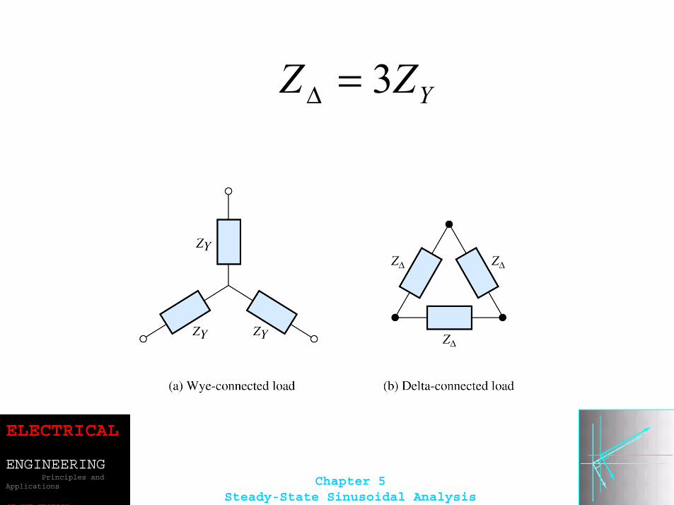
YZZ 3=∆
ELECTRICAL
ENGINEERINGPrinciples and
Applications
SE OND EDITION
Chapter 5Steady-State Sinusoidal Analysis
ELECTRICAL
ENGINEERINGPrinciples and
Applications
SE OND EDITION
Chapter 5Steady-State Sinusoidal Analysis