CHAPTER 5 Particle Replication in Non-wetting Templates:...
18
CHAPTER 5 Particle Replication in Non-wetting Templates: a Platform for Engineering Shape- and Size-specific Janus Particles JOSEPH M. DESIMONE* a,b , JIE-YU WANG a AND YAPEI WANG c a Department of Chemistry, University of North Carolina at Chapel Hill, Chapel Hill, NC 27599, USA; b Department of Chemical and Biomolecular Engineering, North Carolina State University, Raleigh, NC 27695, USA; c Department of Chemistry, Renmin University of China, Beijing 100872, China *E-mail: [email protected] 5.1 Introduction Because of their unique anisotropic characteristics, Janus particles have been assessed as attractive building blocks for self-assembly with desirable supramolecular architectures, leading to the creation of novel functional materials. 1–5 Janus particles with tunable chemistry and physical properties have attracted much attention in the fields of colloidal physics and chemistry for various applications ranging from optoelectronics, e-ink, drug delivery and bioimaging. 6 RSC Smart Materials No. 1 Janus Particle Synthesis, Self-Assembly and Applications Edited by Shan Jiang and Steve Granick # The Royal Society of Chemistry 2012 Published by the Royal Society of Chemistry, www.rsc.org 90 Downloaded by University of North Carolina at Chapel Hill on 08/07/2013 16:22:07. Published on 30 November 2012 on http://pubs.rsc.org | doi:10.1039/9781849735100-00090
Transcript of CHAPTER 5 Particle Replication in Non-wetting Templates:...

CHAPTER 5
Particle Replication inNon-wetting Templates:a Platform for EngineeringShape- and Size-specific JanusParticles
JOSEPH M. DESIMONE*a,b, JIE-YU WANGa ANDYAPEI WANGc
a Department of Chemistry, University of North Carolina at Chapel Hill,
Chapel Hill, NC 27599, USA; b Department of Chemical and Biomolecular
Engineering, North Carolina State University, Raleigh, NC 27695, USA;c Department of Chemistry, Renmin University of China, Beijing 100872,
China
*E-mail: [email protected]
5.1 Introduction
Because of their unique anisotropic characteristics, Janus particles have been
assessed as attractive building blocks for self-assembly with desirable
supramolecular architectures, leading to the creation of novel functional
materials.1–5 Janus particles with tunable chemistry and physical properties
have attracted much attention in the fields of colloidal physics and chemistry
for various applications ranging from optoelectronics, e-ink, drug delivery and
bioimaging.6
RSC Smart Materials No. 1
Janus Particle Synthesis, Self-Assembly and Applications
Edited by Shan Jiang and Steve Granick
# The Royal Society of Chemistry 2012
Published by the Royal Society of Chemistry, www.rsc.org
90
Dow
nloa
ded
by U
nive
rsity
of
Nor
th C
arol
ina
at C
hape
l Hill
on
08/0
7/20
13 1
6:22
:07.
Pu
blis
hed
on 3
0 N
ovem
ber
2012
on
http
://pu
bs.r
sc.o
rg |
doi:1
0.10
39/9
7818
4973
5100
-000
90

Early synthetic strategies for generating Janus particles were focused on self-
assembly and surface modification.7–9 So far, they are still popular as self-
assembly can begin with a wide range of molecular moieties, including DNA
and block copolymers, and surface modification is being extended to more and
more mild reactions which hardly damage the particle interiors. Although the
number of chemical compositions and surface chemistries utilized in these
particle systems is increasing, particle shapes have been largely limited to a
small number of simple geometries. Several recently developed top-down
strategies have overcome this limitation and the creation of high-level
structures has become possible.10–15 This chapter highlights the strategy of
particle replication in non-wetting templates (PRINT) recently developed in
our laboratories to fabricate monodisperse Janus particles with precise control
over the size, shape, chemistry and distribution of the chemically distinct
regions.
5.2 PRINT Technique
The history of the PRINT technique began with the synthesis of a new highly
fluorinated perfluoropolyether (PFPE) elastomer by Rolland et al. in 2004.16,17
This photo-curable resin was demonstrated to have remarkably low surface
energy (8–10 dyn cm21) with respect to other materials. In addition, possessing
the properties of high gas permeability, high elastic recovery, good mechanical
strength and high chemical and solvent resistance sets PFPE apart from the
more commonly used polydimethylsiloxane (PDMS) as a template for micro-
molding. The PRINT technique is a soft lithography technique based on the
use of PFPE molds that is able to mold most hydrophobic and hydrophilic
liquids to generate useful materials in the form of arrays of patterned features,
arrays of particles and isolated particles.
The PRINT process for fabricating isolated particles starts with an etched
silicon master created using standard lithographic techniques in which the
features are raised (Figure 5.1). The photo-curable liquid PFPE resin is then
poured on to the silicon master and allowed to distribute evenly across and wet
the surface of the master template. The resin is then photochemically cross-
linked to form a robust elastomeric PFPE mold that is subsequently peeled
away from the master to reveal micro- or nanoscale cavities on its surface.
Next, a pre-particle solution is cast on a high surface energy sheet [typically
poly(ethylene terephthalate) (PET)] using a Myer rod to form a uniform film
of specified thickness. The sheet is then laminated to the empty PFPE mold
using heat and pressure. When the high surface energy sheet is peeled away,
capillary forces keep the liquid trapped in the mold cavities whereas excess
solution is wicked away by the high surface energy sheet. The pre-particle
solution in the filled mold cavities is then solidified using an appropriate means
(UV light, thermal heating, lyophilization, etc.). Lastly, the solidified particles
in the mold are removed by laminating the filled mold to a sacrificial
harvesting film such as polyvinylpyrrolidinone, poly(vinyl alcohol) or
Particle Replication in Non-wetting Templates: a Platform for Engineering
Shape- and Size-specific Janus Particles 91
Dow
nloa
ded
by U
nive
rsity
of
Nor
th C
arol
ina
at C
hape
l Hill
on
08/0
7/20
13 1
6:22
:07.
Pu
blis
hed
on 3
0 N
ovem
ber
2012
on
http
://pu
bs.r
sc.o
rg |
doi:1
0.10
39/9
7818
4973
5100
-000
90View Online

cyanoacrylate. Peeling the harvesting film away from the mold results in an
array of particles on the harvesting sheet. Free particles can then be collected
by dissolving away the sacrificial adhesive film with an appropriate solvent for
the adhesive and a non-solvent for the particles.
The PRINT technique has several attractive features that make it ideally
suited for particle fabrication owing to the unique properties of the PFPE
mold: (i) the low surface adhesion and elastic deformation of the PFPE mold
facilitate the removal of the connecting flash layer, whereas other lithographic
methods usually need an etching step to remove this scum layer; (ii) the highly
fluorinated nature of the PFPE mold also facilitates the removal of particles
from the mold; and (iii) PFPE has been shown to be compatible with a number
of organic solvents that swell the traditionally used PDMS mold material, thus
allowing PRINT to generate particles using a range of materials with very high
fidelity to the original silicon master.
Another advantage of the PRINT technique is its scalability, allowing for
the fabrication of monodisperse particles with precise and independent control
over the particle size, shape and composition in relatively large quantities using
roll-to-roll processing.18 In addition, the PRINT process is delicate and mild
enough to be compatible with a variety of important cancer therapeutic agents,
detection and imaging agents, various cargos (e.g. DNA, siRNA, protein,
chemotherapy drugs, etc.), targeting ligands (e.g. antibodies, cell targeting
peptides) and functional matrix materials (bioabsorbable polymers, stimuli-
responsive materials, etc.).19 As a result, this new technique is really a platform
technology that makes it possible to study the physical and chemical effects of
particles in drug delivery, electronic devices, colloid science and other
application areas.
Figure 5.1 Schematic illustration of the PRINT process for particle fabrication. (a) APFPE mold is made from a silicon master template; (b) the PFPE moldcavities are then filled with a liquid precursor via capillary flow inconnection with a high surface energy countersheet to remove the excessmaterial from the land areas; (c) various means are used to solidify theprecursor material contained in the PFPE mold cavities; (d) the particlesare transferred from mold cavities using a sacrificial harvesting sheet; (e)free particles are obtained by dissolving away the sacrificial adhesive film.
92 Chapter 5
Dow
nloa
ded
by U
nive
rsity
of
Nor
th C
arol
ina
at C
hape
l Hill
on
08/0
7/20
13 1
6:22
:07.
Pu
blis
hed
on 3
0 N
ovem
ber
2012
on
http
://pu
bs.r
sc.o
rg |
doi:1
0.10
39/9
7818
4973
5100
-000
90View Online
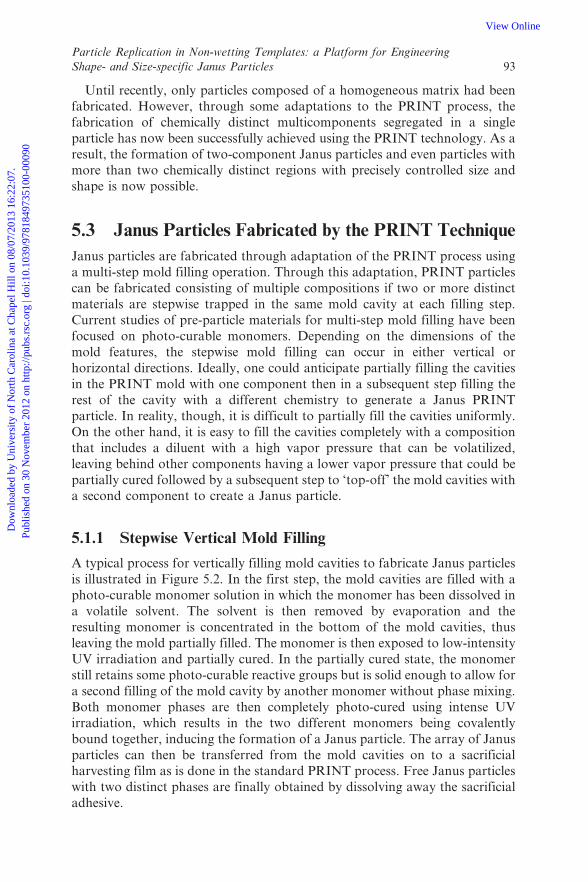
Until recently, only particles composed of a homogeneous matrix had been
fabricated. However, through some adaptations to the PRINT process, the
fabrication of chemically distinct multicomponents segregated in a single
particle has now been successfully achieved using the PRINT technology. As a
result, the formation of two-component Janus particles and even particles with
more than two chemically distinct regions with precisely controlled size and
shape is now possible.
5.3 Janus Particles Fabricated by the PRINT Technique
Janus particles are fabricated through adaptation of the PRINT process using
a multi-step mold filling operation. Through this adaptation, PRINT particles
can be fabricated consisting of multiple compositions if two or more distinct
materials are stepwise trapped in the same mold cavity at each filling step.
Current studies of pre-particle materials for multi-step mold filling have been
focused on photo-curable monomers. Depending on the dimensions of the
mold features, the stepwise mold filling can occur in either vertical or
horizontal directions. Ideally, one could anticipate partially filling the cavities
in the PRINT mold with one component then in a subsequent step filling the
rest of the cavity with a different chemistry to generate a Janus PRINT
particle. In reality, though, it is difficult to partially fill the cavities uniformly.
On the other hand, it is easy to fill the cavities completely with a composition
that includes a diluent with a high vapor pressure that can be volatilized,
leaving behind other components having a lower vapor pressure that could be
partially cured followed by a subsequent step to ‘top-off’ the mold cavities with
a second component to create a Janus particle.
5.1.1 Stepwise Vertical Mold Filling
A typical process for vertically filling mold cavities to fabricate Janus particles
is illustrated in Figure 5.2. In the first step, the mold cavities are filled with a
photo-curable monomer solution in which the monomer has been dissolved in
a volatile solvent. The solvent is then removed by evaporation and the
resulting monomer is concentrated in the bottom of the mold cavities, thus
leaving the mold partially filled. The monomer is then exposed to low-intensity
UV irradiation and partially cured. In the partially cured state, the monomer
still retains some photo-curable reactive groups but is solid enough to allow for
a second filling of the mold cavity by another monomer without phase mixing.
Both monomer phases are then completely photo-cured using intense UV
irradiation, which results in the two different monomers being covalently
bound together, inducing the formation of a Janus particle. The array of Janus
particles can then be transferred from the mold cavities on to a sacrificial
harvesting film as is done in the standard PRINT process. Free Janus particles
with two distinct phases are finally obtained by dissolving away the sacrificial
adhesive.
Particle Replication in Non-wetting Templates: a Platform for Engineering
Shape- and Size-specific Janus Particles 93
Dow
nloa
ded
by U
nive
rsity
of
Nor
th C
arol
ina
at C
hape
l Hill
on
08/0
7/20
13 1
6:22
:07.
Pu
blis
hed
on 3
0 N
ovem
ber
2012
on
http
://pu
bs.r
sc.o
rg |
doi:1
0.10
39/9
7818
4973
5100
-000
90View Online
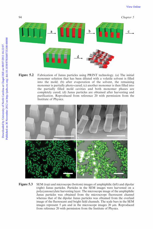
Figure 5.2 Fabrication of Janus particles using PRINT technology. (a) The initialmonomer solution that has been diluted with a volatile solvent is filledinto the mold; (b) after evaporation of the solvent, the remainingmonomer is partially photo-cured; (c) another monomer is then filled intothe partially filled mold cavities and both monomer phases arecompletely cured; (d) Janus particles are obtained after harvesting andpurification. Reproduced from reference 20 with permission from theInstitute of Physics.
Figure 5.3 SEM (top) and microscope (bottom) images of amphiphilic (left) and dipolar(right) Janus particles. Particles in the SEM images were harvested on apolycyanoacrylate harvesting layer. The microscope image of the amphiphilicJanus particles was obtained from the microscrope fluorescent channelwhereas that of the dipolar Janus particles was obtained from the overlaidimage of the fluorescent and bright field channels. The scale bars in the SEMimages represent 5 mm and in the microscope images 20 mm. Reproducedfrom reference 20 with permission from the Institute of Physics.
94 Chapter 5
Dow
nloa
ded
by U
nive
rsity
of
Nor
th C
arol
ina
at C
hape
l Hill
on
08/0
7/20
13 1
6:22
:07.
Pu
blis
hed
on 3
0 N
ovem
ber
2012
on
http
://pu
bs.r
sc.o
rg |
doi:1
0.10
39/9
7818
4973
5100
-000
90View Online

Early examples were constructed using a mold with a feature size of a 2 6 2
6 6 mm rectangular prism. Two-phase Janus particles were fabricated
according to the previously described vertical two-step mold filling strategy.20
Amphiphilic Janus particles were obtained by combining a hydrophilic
monomer [poly(ethylene glycol) monomethyl ether monomethacrylate, Mn 5
1000 g mol21] with a hydrophobic monomer (lauryl acrylate). In addition,
dipolar Janus particles were fabricated by combining a positively charged
monomer (2-aminoethyl methacrylate hydrochloride dissolved in trimethylol-
propane ethoxylate triacrylate) with a negatively charged monomer (acrylic
acid mixed with trimethylolpropane ethoxylate triacrylate). The scanning
electron microscopy (SEM) and optical microscopy images in Figure 5.3
clearly show the biphasic architecture of the resulting Janus particles. For
better identification of the disparate regions in the Janus particles, one of the
blocks was made fluorescent by doping with fluorescein o-acrylate while the
other block without the fluorophore remained dark. By varying the
concentration of the monomer in the monomer solution of the first block,
the volume fraction ratio of the two different regions could be easily
controlled.
5.1.2 Horizontal Stepwise Mold Filling
The stepwise mold filling fabrication of particles in the vertical direction is
limited owing to two issues: (1) higher aspect ratio particles require a stronger
force to pull the particles out of the mold cavities and (2) the etching of silicon
master templates with a high aspect ratio pillar is very challenging. Because of
these limitations, the multistep mold filling PRINT process has been extended
to the horizontal direction as high aspect ratio particles that are lying down
can be much more easily etched in silicon templates than vertically oriented
high aspect ratio features.
Starting with a 20 6 20 6 240 mm rectangular rod as the starting template,
a two-step mold filling process was developed to fabricate triphasic particles.21
First, a dilute solution of a photo-curable hydrophilic monomer in DMF was
used to completely fill the PFPE mold. The solvent was then evaporated and
the remaining monomer was drawn by capillary forces to the ends of the
rectangular cavity. The monomer was then partially cured using a low-
intensity UV light source to convert the monomer into a soft gel while leaving
enough reactive groups to covalently bind subsequent blocks. Subsequently,
the middle, empty cavity of the mold was completely filled with a second
hydrophobic monomer. As shown in Figure 5.4, after the final monomer
composition had been fully cured by intense UV irradiation, a triphasic
architecture with the regions covalently connected together was obtained. The
hydrophilic:hydrophobic ratio in the triphasic structure could be precisely
tuned by simply changing the concentration of the original monomer solution.
As shown in Figure 5.5, the hydrophilic heads of ABA amphiphilic triphasic
rods could be controlled by varying the concentration of the first monomer
Particle Replication in Non-wetting Templates: a Platform for Engineering
Shape- and Size-specific Janus Particles 95
Dow
nloa
ded
by U
nive
rsity
of
Nor
th C
arol
ina
at C
hape
l Hill
on
08/0
7/20
13 1
6:22
:07.
Pu
blis
hed
on 3
0 N
ovem
ber
2012
on
http
://pu
bs.r
sc.o
rg |
doi:1
0.10
39/9
7818
4973
5100
-000
90View Online

mixture. Solely hydrophobic (Figure 5.5a) and hydrophilic (Figure 5.5b)
particles were fabricated as reference samples.
The principle of fabricating triphasic rods has been extended to the
generation of multi-region ABABA rods. In this technique, the mold is
partially filled as before by first diluting a hydrophobic monomer solution
containing a green dye. A second region is then generated using a dilute
hydrophilic monomer solution containing a red dye (Figure 6a), while
retaining an open space in the middle of the mold cavity which is able to be
filled by a third hydrophobic monomer (undiluted) containing a green dye. As
Figure 5.4 Schematic illustration of the formation of triphasic rods and thecorresponding microscope images of the molds in each step (all scalebars 100 mm). To distinguish the middle filled hydrophobic regions fromthe hydrophilic end regions, a photo-curable red dye and a green dyewere premixed into the hydrophilic and hydrophobic monomers,respectively, prior to photo-curing. Reproduced from reference 21 withpermission from the American Chemical Society.
96 Chapter 5
Dow
nloa
ded
by U
nive
rsity
of
Nor
th C
arol
ina
at C
hape
l Hill
on
08/0
7/20
13 1
6:22
:07.
Pu
blis
hed
on 3
0 N
ovem
ber
2012
on
http
://pu
bs.r
sc.o
rg |
doi:1
0.10
39/9
7818
4973
5100
-000
90View Online

shown in Figure 6b and c, five regions arranged as ABABA were observed to
coexist in a particle, demonstrating this to be a powerful tool for building a
library of anisotropic rods possessing tunable multiphases of different
compositions.
Multiphase particles having either tri- or pentaphasic architectures are
centrosymmetric. In order to fabricate asymmetric two-phase rods, centrifugal
Figure 5.5 Array of ABA 20 6 20 6 240 mm triphasic rod particles on harvestingfilm with tunable block dimensions. (a) One-component hydrophobicparticles. (b) One-component hydrophilic particles. (c)–(f) ABA triphasicparticles with different hydrophilic:hydrophobic:hydrophilic ratios cor-responding to the four hydrophilic monomer concentrations of (c) 10, (d)20, (e) 30 and (f) 50 wt%. Images (c)–(f) were captured by overlaying theimages under red and green channels. Scale bar: 200 mm. Reproducedfrom reference 21 with permission from the American Chemical Society.
Figure 5.6 Array of anisotropic rods having multiphases. (a) The diphasic particlestransferred from the partially filled mold at two ends on to acyanoacrylate film. (b) Multiphase particles harvested on a cyanoacrylatefilm. (c) Free multiphase particles separated from cyanoacrylate film. Theimages were captured by overlaying the images under red and greenchannels. Scale bar: 200 mm. Reproduced from reference 21 withpermission from the American Chemical Society.
Particle Replication in Non-wetting Templates: a Platform for Engineering
Shape- and Size-specific Janus Particles 97
Dow
nloa
ded
by U
nive
rsity
of
Nor
th C
arol
ina
at C
hape
l Hill
on
08/0
7/20
13 1
6:22
:07.
Pu
blis
hed
on 3
0 N
ovem
ber
2012
on
http
://pu
bs.r
sc.o
rg |
doi:1
0.10
39/9
7818
4973
5100
-000
90View Online
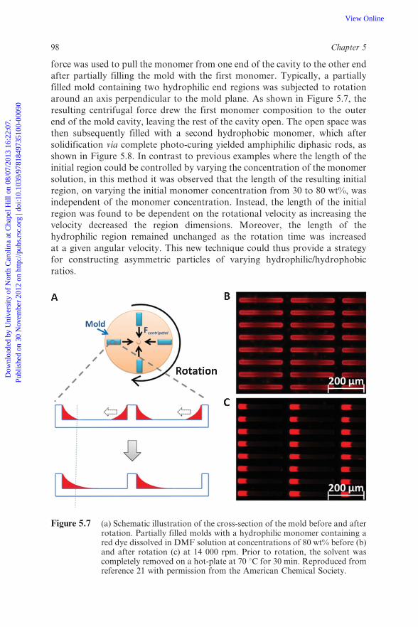
force was used to pull the monomer from one end of the cavity to the other end
after partially filling the mold with the first monomer. Typically, a partially
filled mold containing two hydrophilic end regions was subjected to rotation
around an axis perpendicular to the mold plane. As shown in Figure 5.7, the
resulting centrifugal force drew the first monomer composition to the outer
end of the mold cavity, leaving the rest of the cavity open. The open space was
then subsequently filled with a second hydrophobic monomer, which after
solidification via complete photo-curing yielded amphiphilic diphasic rods, as
shown in Figure 5.8. In contrast to previous examples where the length of the
initial region could be controlled by varying the concentration of the monomer
solution, in this method it was observed that the length of the resulting initial
region, on varying the initial monomer concentration from 30 to 80 wt%, was
independent of the monomer concentration. Instead, the length of the initial
region was found to be dependent on the rotational velocity as increasing the
velocity decreased the region dimensions. Moreover, the length of the
hydrophilic region remained unchanged as the rotation time was increased
at a given angular velocity. This new technique could thus provide a strategy
for constructing asymmetric particles of varying hydrophilic/hydrophobic
ratios.
Figure 5.7 (a) Schematic illustration of the cross-section of the mold before and afterrotation. Partially filled molds with a hydrophilic monomer containing ared dye dissolved in DMF solution at concentrations of 80 wt% before (b)and after rotation (c) at 14 000 rpm. Prior to rotation, the solvent wascompletely removed on a hot-plate at 70 uC for 30 min. Reproduced fromreference 21 with permission from the American Chemical Society.
98 Chapter 5
Dow
nloa
ded
by U
nive
rsity
of
Nor
th C
arol
ina
at C
hape
l Hill
on
08/0
7/20
13 1
6:22
:07.
Pu
blis
hed
on 3
0 N
ovem
ber
2012
on
http
://pu
bs.r
sc.o
rg |
doi:1
0.10
39/9
7818
4973
5100
-000
90View Online
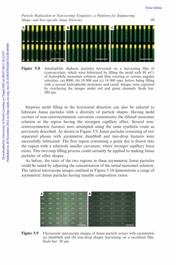
Stepwise mold filling in the horizontal direction can also be tailored to
fabricate Janus particles with a diversity of particle shapes. Having mold
cavities of non-centrosymmetric curvature concentrates the diluted monomer
solution at the region having the strongest capillary effect. Several non-
centrosymmetric features were attempted using the same synthetic route as
previously described. As shown in Figure 5.9, Janus particles consisting of two
separated phases with asymmetric dumbbell and tear-drop features were
successfully fabricated. The first region containing a green dye is drawn into
the region with a relatively smaller curvature, where stronger capillary force
exists. This two-step filling process could certainly be applied to making Janus
particles of other shapes.
As before, the ratio of the two regions in these asymmetric Janus particles
could be tuned by adjusting the concentration of the initial monomer solution.
The optical microscope images outlined in Figure 5.10 demonstrate a range of
asymmetric Janus particles having tunable composition ratios.
Figure 5.8 Amphiphilic diphasic particles harvested on a harvesting film ofcyanoacrylate, which were fabricated by filling the mold with 80 wt%of hydrophilic monomer solution and then rotating at various angularvelocities, (a) 8000, (b) 10 000 and (c) 14 000 rpm, before being fillingwith a second hydrophobic monomer and cured. Images were capturedby overlaying the images under red and green channels. Scale bar:200 mm.
Figure 5.9 Fluorescent microscopy images of Janus particle arrays with asymmetric(a) dumbbell and (b) tear-drop shapes harvesting on a sacrificial film.Scale bar: 50 mm.
Particle Replication in Non-wetting Templates: a Platform for Engineering
Shape- and Size-specific Janus Particles 99
Dow
nloa
ded
by U
nive
rsity
of
Nor
th C
arol
ina
at C
hape
l Hill
on
08/0
7/20
13 1
6:22
:07.
Pu
blis
hed
on 3
0 N
ovem
ber
2012
on
http
://pu
bs.r
sc.o
rg |
doi:1
0.10
39/9
7818
4973
5100
-000
90View Online

5.4 Patchy PRINT Particles
Many examples on selectively creating patches on particle surfaces by means of
partially covering the particles have been reported. For example, patchy
particle surfaces can be achieved either by trapping the particles at an oil/water
interface8 or by arraying particles on a two-dimensional substrate.4 The
PRINT technique is unique in its ability to fabricate more complex shapes
rather than regular spheres. Using PRINT, patchy particles can be fabricated
by surface modification of the solidified particle while either in the mold or on
the harvesting layer. When particles are in the mold, one open face could be
modified to form patchy particles. Once the particles have been transferred on
to a harvesting layer, the other faces could also be modified. Surface
modifications of the PRINT particles using chemical grafting and metal
deposition have been attempted.20
5.4.1 Surface-modified Particles by Chemical Grafting
Two particle shapes made using the PRINT process were selectively modified
via chemical functionalization on one face. The particle shapes used were a 2 62 6 6 mm rectangular-prism and the other a 3 mm diameter hexnut. The
particles were comprised of 67 wt% of the cross-linker PEG428-triacrylate, 20
wt% of PEG1000-monomethyl ether monomethacrylate, 10 wt% of the primary
amine monomer aminoethyl methacrylate (AEM), 2 wt% of the fluorescent
monomer fluorescein o-acrylate and 1 wt% of the photoinitiator 2,2-
diethoxyacetophenone (DEAP). After photo-curing the monomer mixtures
in the mold, the full mold with particles was inverted into a solution of
buffered N-Hydroxysuccinimide (NHS)-rhodamine, which reacted with the
primary amine group in the particles to introduce the rhodamine dye
selectively on one exposed particle surface. The process is illustrated in
Figure 5.11. After reaction, the molds were thoroughly rinsed with water and
dried. The particles were then transferred out of the mold using cyanoacrylate
and further washed with acetone for several times to remove the adhesive
completely.
Figure 5.10 Fluorescent microscope images of asymmetric particles demonstratingdifferent domain ratios resulting from varied concentrations of theinitial monomer solution. Scale bar: 20 mm.
100 Chapter 5
Dow
nloa
ded
by U
nive
rsity
of
Nor
th C
arol
ina
at C
hape
l Hill
on
08/0
7/20
13 1
6:22
:07.
Pu
blis
hed
on 3
0 N
ovem
ber
2012
on
http
://pu
bs.r
sc.o
rg |
doi:1
0.10
39/9
7818
4973
5100
-000
90View Online

The fluorescence microscopy images of the resulting particles with a
selectively functionalized surface are shown in Figure 5.12. The particles
clearly exhibit both green and red fluorescence. The green fluorescence is the
result of the fluorescein o-acrylate incorporated into the bulk of the particles
and the red fluorescence is from the surface-bound rhodamine dye.
5.4.2 Surface-functionalized Particles by Metal Deposition
In addition to chemical grafting to the particle surface while in the mold,
selective vapor deposition of a metal can also be used to achieve chemical
anisotropy on a particle surface. To prepare metal end-capped PRINT
particles, a 10 nm layer of a Pd–Au alloy was sputtered on to the surface of a
filled 2 6 2 6 6 mm rectangular prism mold. After coating, the particles were
harvested by cyanoacrylate and purified. Scanning electron microscopy (SEM)
and energy-dispersive X-ray spectroscopy (EDS) were used to confirm the
presence of the metal alloy selectively on only one face of the particle surface
(Figure 5.13). The metal-coated surface was brighter in the SEM image
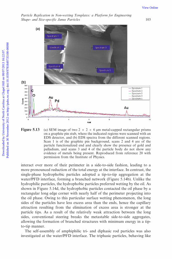
compared with the particle body. In addition, EDS analysis indicated the
presence of the elements carbon and oxygen along the body of the particle
whereas gold and palladium were identified only on the coated end.
Figure 5.11 Reaction scheme for the anisotropic surface functionalization ofprimary amine-containing particles in the mold with NHS-rhodamine.Reproduced from reference 20 with permission from the Institute ofPhysics.
Particle Replication in Non-wetting Templates: a Platform for Engineering
Shape- and Size-specific Janus Particles 101
Dow
nloa
ded
by U
nive
rsity
of
Nor
th C
arol
ina
at C
hape
l Hill
on
08/0
7/20
13 1
6:22
:07.
Pu
blis
hed
on 3
0 N
ovem
ber
2012
on
http
://pu
bs.r
sc.o
rg |
doi:1
0.10
39/9
7818
4973
5100
-000
90View Online

5.5 Self-assembly of Janus PRINT Particles
Being able to fabricate particles comprised of two or more phases allows the
opportunity to direct the self-assembly behaviors of these particles in solution
or at an interface. The PRINT technique in particular allows for the
fabrication of Janus particles with more complex geometries than the typically
used simple spheres. A directed self-assembly study using 20 6 20 6 240 mm
multiphase PRINT rods was conducted at a water/perfluorodecalin (PFD)
interface to demonstrate the dependence of the self-assembly behavior on the
particle architecture.21 The self-assembly of micron-sized particles at a water/
oil interface is mainly attributed to the lateral capillary forces acting between
the particles due to deformation of the oil/water interface.22–24 As controls,
single-phase hydrophilic particles were shown to aggregate side-to-side into
bundles (Figure 5.14a). The morphology of the assembled particles at the
interface was studied using a gel trapping method which allowed replication of
the oil/water interface on a cured PFPE film.25 The single-phase hydrophilic
particles were found to reside on the oil/water interface with the particles
projecting into the water phase. In this case, the particles could not be trapped
in the oil phase as they were mostly confined by the water gel phase. As shown
in Figure 5.14c, the interfacial distortion indicative of a negative meniscus on
the oil surface was replicated. As a result, the hydrophilic particles tended to
Figure 5.12 Fluorescence images of regiospecifically functionalized PRINT particleswhere (a) shows 2 6 2 6 6 mm regiospecifically functionalized rectangularprisms collapsed on polycyanoacrylate, (b) the purified and driedregiospecifically functionalized prisms and (c) and (d) regiospecificallyfunctionalized 3 mm hexnuts. Scale bars: 20 mm. Reproduced fromreference 20 with permission from the Institute of Physics.
102 Chapter 5
Dow
nloa
ded
by U
nive
rsity
of
Nor
th C
arol
ina
at C
hape
l Hill
on
08/0
7/20
13 1
6:22
:07.
Pu
blis
hed
on 3
0 N
ovem
ber
2012
on
http
://pu
bs.r
sc.o
rg |
doi:1
0.10
39/9
7818
4973
5100
-000
90View Online
interact over more of their perimeter in a side-to-side fashion, leading to a
more pronounced reduction of the total energy at the interface. In contrast, the
single-phase hydrophobic particles adopted a tip-to-tip aggregation at the
water/PFD interface, forming a branched network (Figure 5.14b). Unlike the
hydrophilic particles, the hydrophobic particles preferred wetting by the oil. As
shown in Figure 5.14d, the hydrophobic particles contacted the oil phase by a
rectangular long edge corner with nearly half of the perimeter projecting into
the oil phase. Owing to this particular surface wetting phenomenon, the long
sides of the particles have less excess area than the ends, hence the capillary
attraction resulting from the elimination of excess area is stronger at the
particle tips. As a result of the relatively weak attraction between the long
sides, conventional steering breaks the metastable side-to-side aggregates,
allowing the formation of branched structures with minimum energy in a tip-
to-tip manner.
The self-assembly of amphiphilic tri- and diphasic rod particles was also
investigated at the water/PFD interface. The triphasic particles, behaving like
Figure 5.13 (a) SEM image of two 2 6 2 6 6 mm metal-capped rectangular prismson a graphite pin stub, where the indicated regions were scanned with anEDS detector, and (b) EDS spectra from the different scanned regions.Scan 1 is of the graphite pin background, scans 2 and 4 are of theparticle functionalized end and clearly show the presence of gold andpalladium, and scans 3 and 4 of the particle body do not show anyevidence of metals being present. Reproduced from reference 20 withpermission from the Institute of Physics.
Particle Replication in Non-wetting Templates: a Platform for Engineering
Shape- and Size-specific Janus Particles 103
Dow
nloa
ded
by U
nive
rsity
of
Nor
th C
arol
ina
at C
hape
l Hill
on
08/0
7/20
13 1
6:22
:07.
Pu
blis
hed
on 3
0 N
ovem
ber
2012
on
http
://pu
bs.r
sc.o
rg |
doi:1
0.10
39/9
7818
4973
5100
-000
90View Online

bolaamphiphiles, preferred a side-to-side assembly, forming ordered ribbon
structures at the interface, as shown in Figure 5.15a. With regard to the
particle orientation at the interface, a very similar lateral capillary force to
single-phase hydrophilic particles is assumed to provide a driving force in this
directed self-assembly process. However, the triphasic architecture allows each
particle to match the others in a better side-to-side fashion than does the
single-phase hydrophilic particle. It is the difference in interfacial distortion
around the hydrophilic and hydrophobic regions that limits each region of the
triphasic particles to direct the assembly only with others having similar
composition. It was observed that the triphasic particles adopted a bent
conformation at the interface. This is presumably caused by the curved
interface between the hydrophilic and hydrophobic regions and the swelling of
Figure 5.14 Fluorescence microscopic images of different particles assembled at thewater/PFD interface for the (a) hydrophilic and (b) hydrophobicparticles. Scanning electron micrographs are shown for the (c) PFPEmold obtained for the particle trapping experiment for the single-phasehydrophilic particles on the oil surface and (d) PFPE mold for thesingle-phase hydrophobic particles trapped at the oil phase. Self-assembly models are illustrated for the (e) hydrophilic and (f)hydrophobic particles at the water/oil interface. Reproduced fromreference 21 with permission from the American Chemical Society.
104 Chapter 5
Dow
nloa
ded
by U
nive
rsity
of
Nor
th C
arol
ina
at C
hape
l Hill
on
08/0
7/20
13 1
6:22
:07.
Pu
blis
hed
on 3
0 N
ovem
ber
2012
on
http
://pu
bs.r
sc.o
rg |
doi:1
0.10
39/9
7818
4973
5100
-000
90View Online

the hydrophilic regions in water. Interestingly, the diphasic particles, having an
asymmetric structure similar to a molecular surfactant, self-assembled into a
2D bilayer structure at the water/PFD interface (Figure 5.15b). In a bilayer
structure, the side-to-side lateral interactions pull the particles together
forming bundles while the heads of the hydrophobic regions tended to
aggregate by a tip-to-tip lateral interaction. The cooperation of both assemblyfashions thus induces the formation of a bilayer structure, being like the shell
structure of vesicles assembled by traditional surfactants.
5.6 Conclusion and Future Perspectives
The PRINT technique is a leading technology for the fabrication of particles
with precise control over the geometry and composition. The synthesized
particles represent a new paradigm for assembling nanoscale materials into
microscale structures, creating opportunities in optoelectronics, reinforcement
and encapsulation/release strategies. Two-phase Janus particles and also
multiphase particles have been shown to be able to be easily fabricated via a
Figure 5.15 Fluorescent microscopy images of di- and triphasic particles assembledat the water/PFD interface. (a) ABA hydrophilic–hydrophobic–hydro-philic triphasic particles with 50 wt% hydrophilic monomer content asshown previously in Figure 5.7f. (b) AB diphasic particles comprised of80 wt% hydrophilic monomer as previously described in Figure 5.10c.Scale bar of insets: 200 mm. Self-assembly models are illustrated for theparticles at a water/oil interface for the (c) tri- and (d) diphasic particles.Reproduced from reference 21 with permission from the AmericanChemical Society.
Particle Replication in Non-wetting Templates: a Platform for Engineering
Shape- and Size-specific Janus Particles 105
Dow
nloa
ded
by U
nive
rsity
of
Nor
th C
arol
ina
at C
hape
l Hill
on
08/0
7/20
13 1
6:22
:07.
Pu
blis
hed
on 3
0 N
ovem
ber
2012
on
http
://pu
bs.r
sc.o
rg |
doi:1
0.10
39/9
7818
4973
5100
-000
90View Online

multi-step mold filling adaptation of the PRINT technique, thus allowing
precise control over the particle phases. Traditionally, numerous questions in
the field of colloid physics and chemistry are encountered because of the
limitations in particle geometry. Multiphase PRINT particles are now able to
provide a platform to study the effects of composition and particle geometry
on particle–particle interactions in colloid science. The ability to fabricate
multiple components within a single particle is anticipated to open up avenues
to new drug carriers, allowing the encapsulation of several drugs withinhydrophilic or hydrophobic phases in one carrier. In addition, it is envisioned
that the internalization of particles into the various types of cells could be
realized using particles with a Janus architecture.
Janus particles with complex non-spherical architectures provide thepossibility of obtaining novel self-assembled hierarchical superstructures
which show great potential in medical and optoelectronic devices. Being able
to fabricate nanoscale non-spherical Janus particles, although more challen-
ging than the fabrication of micron-sized particles, is very attractive for a host
of research fields.
Acknowledgements
The authors thank the National Science Foundation under Grants DMR-0923604 and DMR-0906985 for their support of this research, and also the STC
program of the National Science Foundation for shared facilities. The authors
acknowledge the careful editing of Dr Douglas E. Betts of Reichhold Inc.
References
1. L. Hong, A. Cacciuto, E. Luijten and S. Granick, Langmuir, 2008, 24,
621–625.
2. Q. Chen, J. K. Whitmer, S. Jiang, S. C. Bae, E. Luijten and S. Granick,
Science, 2011, 331, 199–202.
3. Q. Chen, S. C. Bae and S. Granick, Nature, 2011, 469, 381–385.
4. Q. Chen, E. Diesel, J. K. Whitmer, S. C. Bae, E. Luijten and S. Granick, J.
Am. Chem. Soc., 2011, 133, 7725–7727.
5. N. Glaser, D. J. Adams, A. Boker and G. Krausch, Langmuir, 2006, 22,5227–5229.
6. A. Walther and A. H. E. Muller, Soft Matter, 2008, 4, 663–668.
7. T. Tanaka, M. Okayama, H. Minami and M. Okubo, Langmuir, 2010, 26,
11732–11736.
8. L. Hong, S. Jiang and S. Granick, Langmuir, 2006, 22, 9495–9499.
9. Y. K. Takahara, S. Ikeda, S. Ishino, K. Tachi, K. Ikeue, T. Sakata, T.Hasegawa, H. Mori, M. Matsumura and B. Ohtani, J. Am. Chem. Soc.,
2005, 127, 6271–6275.
10. S. Park, S.-W. Chung and C. A. Mirkin, J. Am. Chem. Soc., 2004, 126,11772–11773.
106 Chapter 5
Dow
nloa
ded
by U
nive
rsity
of
Nor
th C
arol
ina
at C
hape
l Hill
on
08/0
7/20
13 1
6:22
:07.
Pu
blis
hed
on 3
0 N
ovem
ber
2012
on
http
://pu
bs.r
sc.o
rg |
doi:1
0.10
39/9
7818
4973
5100
-000
90View Online
11. K. Liu, Z. Nie, N. Zhao, W. Li, M. Rubinstein and E. Kumacheva,
Science, 2010, 329, 197–200.
12. J.-W. Kim, R. J. Larsen and D. A. Weitz, J. Am. Chem. Soc., 2006, 128,
14374–14377.
13. D. Dendukuri, T. A. Hatton and P. S. Doyle, Langmuir, 2007, 23, 4669–4674.
14. C.-H. Choi, J. Lee, K. Yoon, A. Tripathi, H. A. Stone, D. A. Weitz and
C.-S. Lee, Angew. Chem. Int. Ed., 2010, 49, 7748–7752.15. Y. Wang, T. J. Merkel, K. Chen, C. A. Fromen, D. E. Betts and J. M.
DeSimone, Langmiur, 2011, 27, 524–528.
16. J. P. Rolland, E. C. Hagberg, G. M. Denison, K. R. Carter and J. M.
DeSimone, Angew. Chem. Int. Ed., 2004, 43, 5796–5799.
17. Y. P. Wang, D. E. Betts, J. A. Finlay, L. Brewer, M. E. Callow, J. A.
Callow, D. E. Wendt and J. M. DeSimone, Macromolecules, 2011, 44,
878–885.
18. S. E. A. Gratton, S. S. William, M. E. Napier, P. D. Pohlhaus, Z. Zhou, K.B. Wiles, B. W. Maynor, C. Shen, T. Olafsen, E. T. Samulski and J. M.
DeSimone, Acc. Chem. Res., 2008, 41, 1685–1695.
19. T. J. Merkel, K. P. Herlihy, J. Nunes, R. M. Orgel, J. P. Rolland and J. M.
DeSimone, Langmuir, 2010, 26, 13086–13096.
20. H. Zhang, J. K. Nunes, S. E. A. Gratton, K. P. Herlihy, P. D. Pohlhaus
and J. M. DeSimone, New J. Phys., 2009, 11, 075018.
21. J. Y. Wang, Y. Wang, S. S. Sheiko, D. E. Betts and J. M. Desimone, J.
Am. Chem. Soc., 2012, 134, 5801–5806.22. P. A. Kralchevsky and K. Nagayama, Adv. Colloid Interface Sci., 2000, 85,
145–192.
23. H.-J. Butt and M. Kappl, Adv. Colloid Interface Sci., 2009, 146, 48–60.
24. A. Boker, J. He, T. Emrick and T. P. Russell, Soft Matter, 2007, 3, 1231–1248.
25. N. Bowden, F. Arias, T. Deng and G. M. Whitesides, Langmuir, 2001, 17,
1757–1765.
Particle Replication in Non-wetting Templates: a Platform for Engineering
Shape- and Size-specific Janus Particles 107
Dow
nloa
ded
by U
nive
rsity
of
Nor
th C
arol
ina
at C
hape
l Hill
on
08/0
7/20
13 1
6:22
:07.
Pu
blis
hed
on 3
0 N
ovem
ber
2012
on
http
://pu
bs.r
sc.o
rg |
doi:1
0.10
39/9
7818
4973
5100
-000
90View Online


![PAUL L. HOFFMAN, ESQ. [S.B.# 71244] SCHONBRUN, DESIMONE, … · 2015. 2. 26. · PAUL L. HOFFMAN, ESQ. [S.B.# 71244] SCHONBRUN, DESIMONE, SEPLOW, HARRIS & HOFFMAN LLP 723 Ocean Front](https://static.fdocuments.us/doc/165x107/60df01bfe7be1339c5446a23/paul-l-hoffman-esq-sb-71244-schonbrun-desimone-2015-2-26-paul-l.jpg)