
Chapter 5 Measurement of Atmospheric Pressure
27
i Chapter 5 Measurement of Atmospheric Pressure CONTENTS 5.1 Definition and Units ··········································································································································· 1 5.1.1 Definition ·····························································································································································1 5.1.2 Units ·····································································································································································1 5.2 Principle of Atmospheric Pressure Measurement ······················································································ 1 5.2.1 Mercury Barometer ···········································································································································1 (1) Principle of mercury barometer···············································································································1 (2) Structure of the Fortin barometer·············································································································2 (3) Handling precautions for mercury···········································································································3 (4) Correction of barometer readings············································································································3 (a) Corrections on index error ··············································································································3 (b) Corrections for temperature ············································································································3 (c) Corrections for gravity ····················································································································4 5.2.2 Aneroid Instruments ··········································································································································4 5.2.2.1 Aneroid Barometer ············································································································································4 5.2.2.2 Aneroid Barograph ············································································································································5 5.2.3 Electronic Barometer·········································································································································6 5.2.3.1 Cylindrical resonator barometer ·······················································································································6 5.2.3.2 Electrostatic capacity barometer·······················································································································7 5.2.4 Reduction to Mean Sea Level···························································································································8 5.3 Maintenance ······················································································································································ 10 5.3.1 Maintenance of the Mercury Barometer······································································································ 10 5.3.2 Aneroid Instruments ······································································································································· 10 5.3.2.1 Aneroid barometer·········································································································································· 10 5.3.2.2 Aneroid barograph·········································································································································· 10 5.3.3 Electronic Barometer······································································································································ 10 5.3.3.1 Cylindrical resonator ······································································································································ 10 5.3.3.2 Electrostatic capacity barometer·····················································································································11 5.4 Calibration ························································································································································· 11 5.4.1 Mercury Barometer ·········································································································································11 5.4.2 Aneroid Barometer ··········································································································································11 5.4.3 Electronic Barometer(Cylindrical resonator barometer, Electrostatic capacity barometer) ····················· 12 5.5 Repair·································································································································································· 12 5.5.1 Mercury Barometer ········································································································································ 12
Transcript of Chapter 5 Measurement of Atmospheric Pressure
i
Chapter 5 Measurement of Atmospheric Pressure
CONTENTS
5.1 Definition and Units ··········································································································································· 1
5.1.1 Definition ·····························································································································································1
5.1.2 Units ·····································································································································································1
5.2 Principle of Atmospheric Pressure Measurement ······················································································ 1
5.2.1 Mercury Barometer ···········································································································································1
(1) Principle of mercury barometer ···············································································································1
(2) Structure of the Fortin barometer·············································································································2
(3) Handling precautions for mercury···········································································································3
(4) Correction of barometer readings ············································································································3
(a) Corrections on index error ··············································································································3
(b) Corrections for temperature ············································································································3
(c) Corrections for gravity ····················································································································4
5.2.2 Aneroid Instruments ··········································································································································4
5.2.2.1 Aneroid Barometer ············································································································································4
5.2.2.2 Aneroid Barograph ············································································································································5
5.2.3 Electronic Barometer ·········································································································································6
5.2.3.1 Cylindrical resonator barometer ·······················································································································6
5.2.3.2 Electrostatic capacity barometer ·······················································································································7
5.2.4 Reduction to Mean Sea Level ···························································································································8
5.3 Maintenance ······················································································································································ 10
5.3.1 Maintenance of the Mercury Barometer ······································································································ 10
5.3.2 Aneroid Instruments ······································································································································· 10
5.3.2.1 Aneroid barometer ·········································································································································· 10
5.3.2.2 Aneroid barograph ·········································································································································· 10
5.3.3 Electronic Barometer ······································································································································ 10
5.3.3.1 Cylindrical resonator ······································································································································ 10
5.3.3.2 Electrostatic capacity barometer ····················································································································· 11
5.4 Calibration ························································································································································· 11
5.4.1 Mercury Barometer ········································································································································· 11
5.4.2 Aneroid Barometer ·········································································································································· 11
5.4.3 Electronic Barometer(Cylindrical resonator barometer, Electrostatic capacity barometer) ····················· 12
5.5 Repair ·································································································································································· 12
5.5.1 Mercury Barometer ········································································································································ 12
ii
5.5.2 Aneroid Instruments ······································································································································· 13
5.5.2.1 Aneroid barometer ·········································································································································· 13
5.5.2.2 Aneroid barograph ·········································································································································· 13
5.5.3 Electronic Barometer ······································································································································ 13
5.6 Transport ···························································································································································· 14
5.6.1 Mercury Barometer ········································································································································ 14
(1) Method of transport ······························································································································· 14
(a) Removing the mercury barometer ······························································································ 14
(b) Turning the mercury barometer upside down ············································································ 14
(c) Storing the mercury barometer in a leather carrying case ························································· 14
(2) Precautions of transport ························································································································· 14
5.6.2 Aneroid Instruments ······································································································································· 15
5.7 Installation ·························································································································································· 15
5.7.1 Mercury Barometer ········································································································································ 15
(1) Checking the mercury barometer ········································································································· 15
(2) Turning the mercury barometer back to a vertical setting ·································································· 15
(3) Test for the presence of gas in the barometer tube ·············································································· 15
(4) Checking the attached thermometer ····································································································· 15
(5) Checking the hanger plate ····················································································································· 15
(6) Installing the mercury barometer ·········································································································· 15
5.7.2 Aneroid Instruments ······································································································································· 16
5.7.2.1 Aneroid barometer ·········································································································································· 16
(1) Pre-install inspection ······························································································································ 16
(2) Pre-install adjustment ···························································································································· 16
(3) Installing the aneroid barometer ··········································································································· 16
5.7.2.2 Aneroid Barograph ········································································································································· 16
(1) Pre-install inspection ······························································································································ 16
(2) Pre-install adjustment ···························································································································· 17
(3) Installation of the aneroid barograph ···································································································· 17
5.7.3 Electronic Barometer ······································································································································ 17
5.8 Practical Training ············································································································································· 17
5.8.1 Aneroid Barometer ········································································································································· 17
5.8.2 Aneroid Barograph ········································································································································· 17
5.8.3 Disassembling and Cleaning the Mercury Barometer ················································································· 17
(1) Preparation and precautions ·················································································································· 17
(2) Disassembling the mercury cistern ······································································································ 18
(3) Draining mercury from the mercury cistern ························································································ 18
iii
(4) Disassemble the mercury cistern glass cylinder ·················································································· 18
(5) Filtering mercury and cleaning components ······················································································· 19
(6) Assembling the mercury cistern glass cylinder ··················································································· 19
(7) Filling mercury ······································································································································· 20
(8) Assembling the mercury cistern ··········································································································· 20
(9) Cleaning the graduation protective glass tube ····················································································· 20
(10) Inspecting the barometer ······················································································································· 21
1
Chapter 5 Measurement of Atmospheric Pressure
5.1 Definition and Units 5.1.1 Definition The atmospheric pressure is the force exerted by the weight of the Earth's atmosphere, expressed
per unit area in a given horizontal cross-section. Thus, the atmospheric pressure is equal to the
weight of a vertical column of air above the Earth's surface, extending to the outer limits of the
atmosphere. 5.1.2 Units In meteorology, atmospheric pressure is reported in hectopascals (hPa). 1 hPa is equal to 100 Pa,
the pascal being the basic SI (System of International Unit) . 1 Pa is equal to 1 Newton per square
meter (N/m2). And 1 hPa is equal to 1mb that was used formerly.
The scales of all barometers used for meteorological purposes should be graduated in hPa.
Some barometers are graduated in the unit inHg or mmHg. Under standard conditions, the
pressure exerted by a pure mercury column which is 760 mm high is 1013.250 hPa, so the
conversion factors are represented as follows:
1 hPa = 0.750062 mmHg;
1 mmHg = 1.333224 hPa.
And because of the relation between inch and mm (1 inch = 25.4 mm), the following conversion
coefficients are provided:
1 hPa = 0.029530 inHg;
1 inHg = 33.8639 hPa;
1 mmHg = 0.03937008 inHg.
Pressure data measured with the barometer should preferably be expressed in hectopascals (hPa).
5.2 Principle of Atmospheric Pressure Measurement
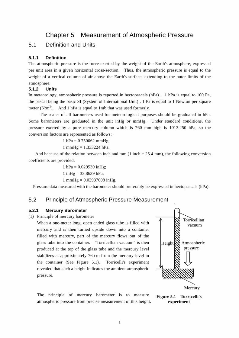
5.2.1 Mercury Barometer (1) Principle of mercury barometer
When a one-meter long, open ended glass tube is filled with
mercury and is then turned upside down into a container
filled with mercury, part of the mercury flows out of the
glass tube into the container. "Torricellian vacuum" is then
produced at the top of the glass tube and the mercury level
stabilizes at approximately 76 cm from the mercury level in
the container (See Figure 5.1). Torricelli's experiment
revealed that such a height indicates the ambient atmospheric
pressure.
The principle of mercury barometer is to measure
atmospheric pressure from precise measurement of this height. Figure 5.1 Torricelli's
experiment
Mercury
Atmospheric pressure
Height
Torricellian vacuum
2
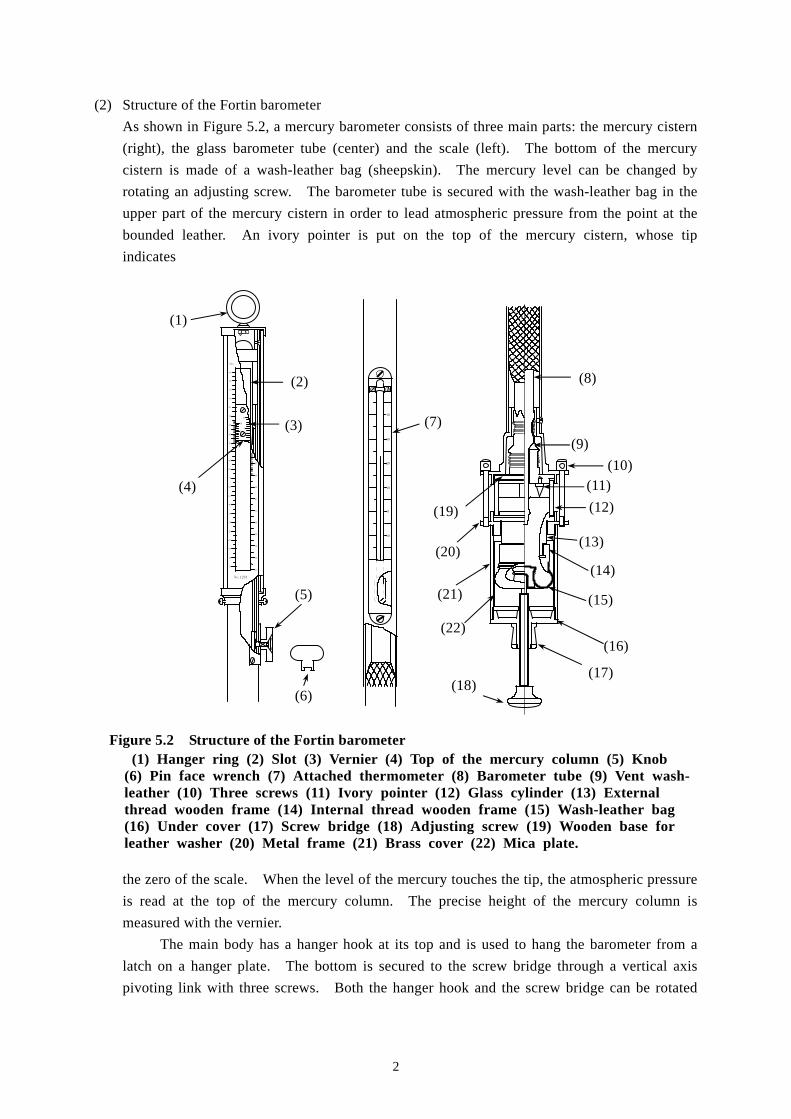
(2) Structure of the Fortin barometer
As shown in Figure 5.2, a mercury barometer consists of three main parts: the mercury cistern
(right), the glass barometer tube (center) and the scale (left). The bottom of the mercury
cistern is made of a wash-leather bag (sheepskin). The mercury level can be changed by
rotating an adjusting screw. The barometer tube is secured with the wash-leather bag in the
upper part of the mercury cistern in order to lead atmospheric pressure from the point at the
bounded leather. An ivory pointer is put on the top of the mercury cistern, whose tip
indicates
Figure 5.2 Structure of the Fortin barometer (1) Hanger ring (2) Slot (3) Vernier (4) Top of the mercury column (5) Knob (6) Pin face wrench (7) Attached thermometer (8) Barometer tube (9) Vent wash- leather (10) Three screws (11) Ivory pointer (12) Glass cylinder (13) External thread wooden frame (14) Internal thread wooden frame (15) Wash-leather bag (16) Under cover (17) Screw bridge (18) Adjusting screw (19) Wooden base for leather washer (20) Metal frame (21) Brass cover (22) Mica plate.
the zero of the scale. When the level of the mercury touches the tip, the atmospheric pressure
is read at the top of the mercury column. The precise height of the mercury column is
measured with the vernier.
The main body has a hanger hook at its top and is used to hang the barometer from a
latch on a hanger plate. The bottom is secured to the screw bridge through a vertical axis
pivoting link with three screws. Both the hanger hook and the screw bridge can be rotated
hPa
1050
90
80
70
60
40
30
20
10
1000
90
80
60
40
30
20
10
70
950
90
80
70
900
650
70
60
80
90
700
10
20
30
40
5
10
5
10
No.1234
40
30
20
10
0
10
(1)
(4)
(2)
(3)
(5)
(6)
(7)
(8)
(9)
(10) (11)
(12)
(13)
(14)
(15)
(16)
(17) (18)
(19)
(20)
(21)
(22)
3
while the barometer is set on the hanger plate. This allows verticality checks at any time.
A mica plate is wound inside the brass cylinder to prevent the direct contact between
brass and the wash-leather bag. The plate serves as a heat insulator as well as prevents
contamination, discoloration, and wear.
(3) Handling precautions for mercury
High-purity distilled and refined mercury is used in mercury barometers. When the mercury
surface oxidizes, the interface between the surface and the ivory pointer becomes unclear.
Heavily contaminated mercury surface requires cleaning. Since mercury is a toxic substance,
it is necessary to pay attention to the following when handling mercury.
1) A container of mercury must be sealed tightly to prevent leakage and breakage. Do not
put mercury into any metal containers as mercury reacts and amalgamates almost all
metals except for iron.
2) The floor of the room where mercury is stored or used in large amounts should be shielded
and laid with an impervious covering. It must not be stored together with other
chemicals, especially with ammonia or acetylene.
3) Mercury has a relatively low boiling point of 357 °C, and produces dangerous poisonous
gas if on fire. It must not be stored close to a heat source.
4) Check the mercury handling room and personnel periodically to make sure that the
amount of mercury does not exceed the dangerous limit. (The environmental regulation
on water contamination affecting personal health limits the total amount of mercury to
0.0005 mg/l.)
(4) Correction of barometer readings
The mercury barometer’s reading should be corrected to the one and the standard condition.
Standard condition is defined as a temperature of 0 °C, where the density of mercury is
13.5951 g/cm3 and a gravity acceleration of 980.665 cm/s2.
During actual observation, the reading should be corrected for the index error,
temperature correction, and gravity acceleration as follows:
(a) Corrections on index error
Individual mercury barometers include index errors (difference between the value
indicated by an individual instrument and that of the standard). The index error is found
by comparison with the standard, and the value is stated on a "comparison certificate".
(b) Corrections for temperature
The temperature correction means to correct a barometric reading, obtained at a certain
temperature, to a value when mercury and graduation temperatures are 0 °C. The
temperature of the attached thermometer is used for this purpose.
The height of the mercury column varies with temperature, even the atmospheric
pressure is unchanged. The graduation of the barometer is engraved so that the correct
pressure is indicated when temperature is 0 °C. In a case that when temperature is above
0 °C, the graduation expands and the measured value will be smaller than the true value.
This effect of temperature must be corrected from these two aspects collectively.
4
Correction for the expansion and contraction of mercury is much larger than that for the
expansion and contraction of the graduation.
The correction value for temperature Ct is expressed as follows:
where:
H hPa is the barometric reading after the correction for index error.
t °C is the temperature indicated by the attached thermometer.
is the volume expansion coefficient of mercury.
is the linear expansion coefficient of the tube.
There is a small difference in absolute values for correction between temperatures
below and above 0 °C. The values for correction at temperatures above 0 °C are
negative and those below 0 °C are positive.
(c) Corrections for gravity
Gravity affects the height of the mercury column. After the corrections for index error
and temperature, the reading under the local acceleration of gravity has to be reduced to
the one under the standard gravity acceleration. This is called corrections for gravity.
The gravity value for correction Cg is derived by:
where:
g0 is the standard gravity acceleration.
g is the gravity acceleration at an observing point.
H is the barometric reading after the index error and temperature corrections
H0 is the value already corrected for gravitation.
The gravity acceleration used in corrections for gravity value is calculated to the
fifth decimal place, in m/s2. When the gravity acceleration at the observing point is
larger than the standard gravity acceleration, the gravity value for correction is positive.
Otherwise, the value for correction is negative.
To use a barometer for regular observations at a particular location, a synthesis
correction table that summarizes values for correction for index error, temperature and
gravity should be used.
5.2.2 Aneroid Instruments
5.2.2.1 Aneroid Barometer Aneroid barometers have lower accuracy than mercury barometers, but thanks to their compact and
portable configuration, aneroid barometers are easier to handle and use, and suitable for
self-recording.
An aneroid barometer measures the distortion of an evacuated, sealed elastic capsule inside
Ct Ht
t
( ) 1
C H H Hg g
gg
00
0
5
with change in atmospheric pressure. The aneroid barometer consists of a barometer capsule, a
spring to prevent the barometer capsule from being crushed by the atmospheric pressure, and gears
and levers that intensify and transmit small amount of variations.
The elasticity of the barometer capsule varies depending on temperature. A bimetallic plate
is used for temperature compensation. Once pressure distort an elastic body, it doesn’t completely
return to its original shape even after the pressure is relieved. Due to this characteristics called
hysteresis, an error will arrive from the sharp change in atmospheric pressure and the error will be
subjected to secular change. To prevent this, special materials are used for the elastic body.
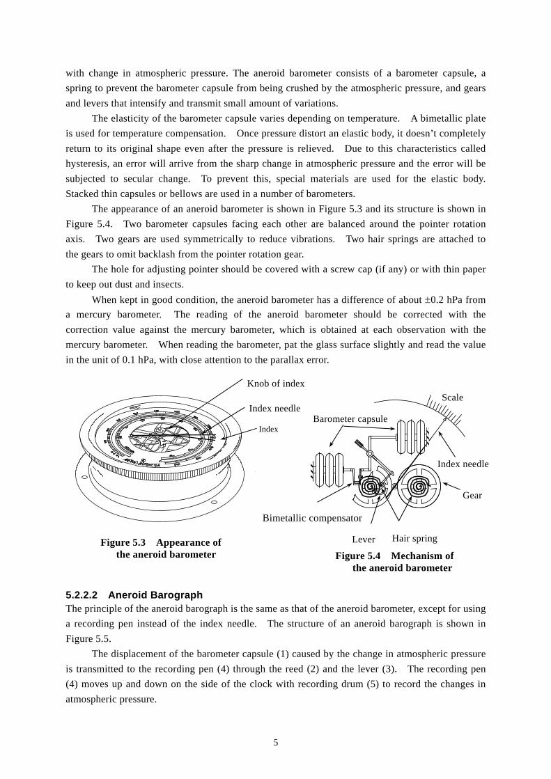
Stacked thin capsules or bellows are used in a number of barometers.
The appearance of an aneroid barometer is shown in Figure 5.3 and its structure is shown in
Figure 5.4. Two barometer capsules facing each other are balanced around the pointer rotation
axis. Two gears are used symmetrically to reduce vibrations. Two hair springs are attached to
the gears to omit backlash from the pointer rotation gear.
The hole for adjusting pointer should be covered with a screw cap (if any) or with thin paper
to keep out dust and insects.
When kept in good condition, the aneroid barometer has a difference of about 0.2 hPa from
a mercury barometer. The reading of the aneroid barometer should be corrected with the
correction value against the mercury barometer, which is obtained at each observation with the
mercury barometer. When reading the barometer, pat the glass surface slightly and read the value
in the unit of 0.1 hPa, with close attention to the parallax error.
5.2.2.2 Aneroid Barograph The principle of the aneroid barograph is the same as that of the aneroid barometer, except for using
a recording pen instead of the index needle. The structure of an aneroid barograph is shown in
Figure 5.5.
The displacement of the barometer capsule (1) caused by the change in atmospheric pressure
is transmitted to the recording pen (4) through the reed (2) and the lever (3). The recording pen
(4) moves up and down on the side of the clock with recording drum (5) to record the changes in
atmospheric pressure.
Figure 5.3 Appearance of the aneroid barometer Figure 5.4 Mechanism of
the aneroid barometer
Scale
Index needle
Gear
Hair spring Lever
Barometer capsule
Knob of index
Index needle
Index
Bimetallic compensator
6
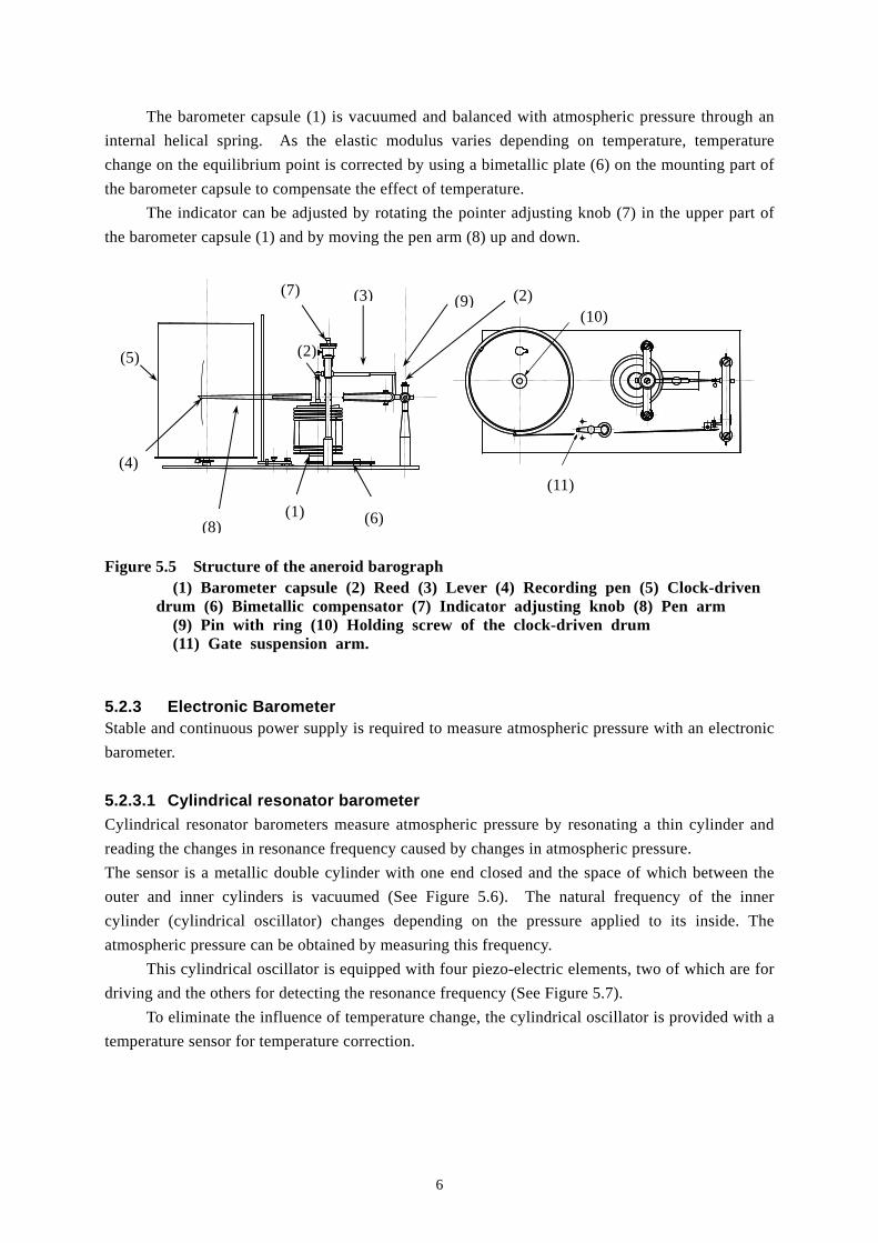
The barometer capsule (1) is vacuumed and balanced with atmospheric pressure through an
internal helical spring. As the elastic modulus varies depending on temperature, temperature
change on the equilibrium point is corrected by using a bimetallic plate (6) on the mounting part of
the barometer capsule to compensate the effect of temperature.
The indicator can be adjusted by rotating the pointer adjusting knob (7) in the upper part of
the barometer capsule (1) and by moving the pen arm (8) up and down.
Figure 5.5 Structure of the aneroid barograph (1) Barometer capsule (2) Reed (3) Lever (4) Recording pen (5) Clock-driven drum (6) Bimetallic compensator (7) Indicator adjusting knob (8) Pen arm (9) Pin with ring (10) Holding screw of the clock-driven drum (11) Gate suspension arm.
5.2.3 Electronic Barometer Stable and continuous power supply is required to measure atmospheric pressure with an electronic
barometer.
5.2.3.1 Cylindrical resonator barometer
Cylindrical resonator barometers measure atmospheric pressure by resonating a thin cylinder and
reading the changes in resonance frequency caused by changes in atmospheric pressure.
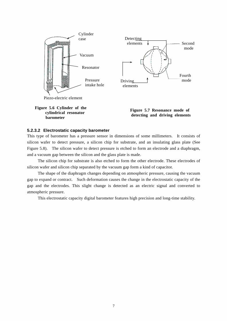
The sensor is a metallic double cylinder with one end closed and the space of which between the
outer and inner cylinders is vacuumed (See Figure 5.6). The natural frequency of the inner
cylinder (cylindrical oscillator) changes depending on the pressure applied to its inside. The
atmospheric pressure can be obtained by measuring this frequency.
This cylindrical oscillator is equipped with four piezo-electric elements, two of which are for
driving and the others for detecting the resonance frequency (See Figure 5.7).
To eliminate the influence of temperature change, the cylindrical oscillator is provided with a
temperature sensor for temperature correction.
(1)
(2)
(3)
(4)
(5)
(6)
(7)
(8)
(9) (2)(10)
(11)
7
5.2.3.2 Electrostatic capacity barometer This type of barometer has a pressure sensor in dimensions of some millimeters. It consists of
silicon wafer to detect pressure, a silicon chip for substrate, and an insulating glass plate (See
Figure 5.8). The silicon wafer to detect pressure is etched to form an electrode and a diaphragm,
and a vacuum gap between the silicon and the glass plate is made.
The silicon chip for substrate is also etched to form the other electrode. These electrodes of
silicon wafer and silicon chip separated by the vacuum gap form a kind of capacitor.
The shape of the diaphragm changes depending on atmospheric pressure, causing the vacuum
gap to expand or contract. Such deformation causes the change in the electrostatic capacity of the
gap and the electrodes. This slight change is detected as an electric signal and converted to
atmospheric pressure.
This electrostatic capacity digital barometer features high precision and long-time stability.
Figure 5.6 Cylinder of the cylindrical resonator
barometer
Cylinder case
Vacuum
Resonator
Pressure intake hole
Piezo-electric element
Detecting elements
Driving elements
Second mode
Fourth mode
Figure 5.7 Resonance mode of detecting and driving elements

8
5.2.4 Reduction to Mean Sea Level To compare the atmospheric pressure value at a certain location to a value at another location, it is
necessary to convert the values at the same referential altitude. It is internationally decided to use
the mean sea level as the referential altitude, and the conversion is called reduction to mean sea
level.
Various kinds of methods of the reduction are used in individual countries. For international
comparisons, however, methods should be standardized to ensure data interchangeability. Two basic
equations, hydrostatic equation and state of ideal gas equation are used in each country.
Differences among the methods are found only in the ways to calculate the gravity acceleration and
the mean virtual temperature.
When the vertical distribution of air temperature and humidity between the mean sea level
and the observation point are known, reduction to mean sea level can be made accurately.
However, the air temperature and humidity just at the observation point are generally known.
Therefore, the atmospheric pressure at mean sea level is obtained assuming the standard vertical
distribution of air temperature and humidity
Suppose there is a vertical air column from the observation point to the mean sea level. The
relation between atmospheric pressure P at the observing point, in hPa, and atmospheric pressure P0
at mean sea level, in hPa, is given by:
Figure 5.8 Pressure sensor of the electrostatic capacity barometer
Vacuum gap
Electrostatic
capacity
: large
Atmospheric pressure : small Atmospheric pressure : Large
Electrostatic
capacity
: small
Silicon substrate
Electrode Ⅱ
Glass substrate
Vacuum gap
Electrode interval
Electrode ⅠMeasurement of
electrostatic capacity
Atmospheric pressure
Silicon
diaphragm
9
where:
Tv is the virtual temperature of the vertical air column, in K.
R is the gas constant of dry air, in Jkg-1K-1.
Z is the height from mean sea level to the barometer, in meters.
Assuming that "g" is constant and is equal to the gravity acceleration at the observing point.
The mean of virtual temperature is given by:
It results:
Therefore, the reduction to mean sea level value P is given by:
Now TVm is expressed as: TVm=273.15+tm+m (K), where tm is the average temperature of the air
column, m is the effect of air humidity. Assuming the lapse rate of air temperature to be 0.5℃
/100m results:
where:
t is the air temperature at the observing point.
The value of m is statistically determined as a function
of the average air temperature. The relationship
between tm and m is graphically shown in Figure 5.9.
This is statistically derived from surface observation
data obtained at eight meteorological observatories in
Japan. This relationship is almost the same as that in the lower atmosphere under average
lnP
P R
z gdz
TV
0
0
1
TZz dz
T
Vm
V
0
P PgZ
RTVm0
exp
P P P PgZ
RTVm
0 1exp
t t Zm 0 005 2.
Figure 5.9 Relationship between m and tm
m
tm
10
conditions in Japan. The value of "R" is 287.05 Jkg-1K-1. Use this formula to calculate the
reduction to one decimal place to mean sea level value P as a function of air temperature t and
atmospheric pressure P at the observing point. It is convenient to tabulate the reductions in
advance. The air temperature at the observing point t should be the one at the height of the
barometer, but the air temperature at the observation field is used instead as the difference is
negligible. Similarly, "g" should be the average value down to the mean sea level, but its
influence is also negligible.
m = (Atm+B) tm + C
tm < -30.0 ゚ C ; m = 0.09
-30.0 tm < 0.0 ; A = 0.000489, B = 0.0300, C = 0.550
0.0 tm < 20.0 ; A = 0.002850, B = 0.0165, C = 0.550
20.0 tm < 33.8 ; A = -0.006933, B = 0.4687, C = -4.580
33.8 tm ; m = 3.34
5.3 Maintenance 5.3.1 5.3.1 Maintenance of the Mercury Barometer The maintenance of mercury barometers is carried out in the following ways:
1) Once a month, brush dust off the outer surface with a soft brush, and wipe metal and glass
parts with a soft cloth. Check the barometer for flaws and cracks.
2) If dirt collects on the mercury level where the mercury comes into contact with the ivory
pointer, turn the adjusting screw as shown in Figure 5.2 to lower level by approximately 3 mm.
Restore the adjusting screw, and dirt will be removed. At this time, be careful not to shake
the main body in an attempt to remove the dirt, as the inside of the glass tube may become
dirty above the mercury level, resulting in unclear readings.
3) The degree of vacuum should not be checked unless it is definitely necessary to do.
5.3.2 Aneroid Instruments 5.3.2.1 Aneroid barometer
Clean the surface or the glass part of the aneroid barometer with a soft cloth or brush every week.
(See Figures 5.3 and 5.4.)
5.3.2.2 Aneroid barograph
Check the aneroid barograph as indicated in Chapter 2: Measurement of temperature, and when
there is a difference of 0.3 hPa or more between the reading of the aneroid barograph and that of
the mercury barometer, turn the indicator adjusting screw (7) to adjust the indicator in Figure 5.5.
5.3.3 Electronic Barometer
5.3.3.1 Cylindrical resonator barometer
As the humid air in the sensor of the cylindrical resonator barometer results in an error of
11
approximately 0.1 hPa in the pressure reading. Replace the desiccant enclosed near the sensor
every month.
5.3.3.2 Electrostatic capacity barometer
Electrostatic capacity barometers have high performance and stability, requiring no daily
maintenance.
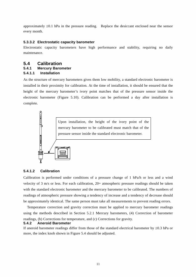
5.4 Calibration 5.4.1 Mercury Barometer 5.4.1.1 Installation
As the structure of mercury barometers gives them low mobility, a standard electronic barometer is
installed in their proximity for calibration. At the time of installation, it should be ensured that the
height of the mercury barometer’s ivory point matches that of the pressure sensor inside the
electronic barometer (Figure 5.10). Calibration can be performed a day after installation is
complete.
5.4.1.2 Calibration
Calibration is performed under conditions of a pressure change of 1 hPa/h or less and a wind
velocity of 3 m/s or less. For each calibration, 20+ atmospheric pressure readings should be taken
with the standard electronic barometer and the mercury barometer to be calibrated. The numbers of
readings of atmospheric pressure showing a tendency of increase and a tendency of decrease should
be approximately identical. The same person must take all measurements to prevent reading errors.
Temperature correction and gravity correction must be applied to mercury barometer readings
using the methods described in Section 5.2.1 Mercury barometers, (4) Correction of barometer
readings, (b) Corrections for temperature, and (c) Corrections for gravity. 5.4.2 Aneroid Barometer If aneroid barometer readings differ from those of the standard electrical barometer by 0.3 hPa or
more, the index knob shown in Figure 5.4 should be adjusted.
Upon installation, the height of the ivory point of the
mercury barometer to be calibrated must match that of the
pressure sensor inside the standard electronic barometer.
12
5.4.3 Electronic Barometer (Cylindrical resonator barometer, Electrostatic capacity barometer)
5.4.3.1 Installation
For electronic barometer calibration, the barometer to be calibrated and the standard electronic
barometer must be connected with a pipe, and a manual pressure adjuster must be used for setting
as shown in Figure 5.11. Upon installation, the pressure sensors inside both barometers must be at
the same height. Installation should be completed a day before calibration to allow the instruments
to acclimatize to room temperature.
5.4.3.2 Pressure inspection
Prior to calibration, the pressure should be gradually changed throughout the entire calibration
range a few times using the manual adjuster. Comparative measurement at the calibration points
should then be performed as described below.
Comparative measurement must be performed at least three times each with upward and downward
pressure changes. The difference between the readings of the standard barometer and the barometer
to be calibrated at each point should be recorded, and the average of the difference at each point can
be taken as the error index for each calibration point.
Calibration points: 880, 920, 960, 1,000, 1,040 (hPa)
*If the specified facilities for pressure inspection are not available, an alternative simplified
method can be used in which the barometer to be calibrated and the standard electronic
barometer are placed at the same height in the atmosphere. Approximately 20 barometer
readings are then taken to determine the correction value at atmospheric pressure.
5.5 Repair 5.5.1 Mercury Barometer When the difference in observation values increases between the mercury and the aneroid
Electronic barometer to be
calibrated Standard Electric Barometaer
Manual pressure adjuster
13
barometers and the mercury barometer appears to be defective, repair it following the instructions
as described below (See Figure 5.2).
1) The difference increase is probably caused by the impaired vacuum or the loose mounting of
the ivory pointer. When the vacuum becomes impaired, drain and refill the mercury. When
the ivory pointer mounting part becomes loose, disassemble and screw it up tightly.
2) When the knob (5) used to move the vernier (3) comes loose and causes a large backlash when
the graduation is adjusted, tighten two nuts on the knob with a special tool (pin face wrench)
(6).
3) Do not lubricate the adjusting screw (18) and the knob (5) excessively. Excess oil will spread
and melt paint varnish, causing sticky thread. It will stiffen the screw all the more. In
addition, the oil will soak into the wash-leather bag (15) and the wooden part, and contaminate
the mercury. When the adjusting screw (18) is stiff, it is probably because the screw is bent
or the thread is dirty. In these cases, replace the screw or remove and clean it with a brush
and cloth.
4) When the level of a mercury barometer seems to be not working correctly due to an earthquake,
for example, loosen three screws of the vertical axis pivoting link. Check the level and
tighten the screws again. 5.5.2 Aneroid Instruments 5.5.2.1 Aneroid barometer
The aneroid barometer is a very precise instrument, and it cannot be easily disassembled or repaired
on site.
5.5.2.2 Aneroid barograph
Repair aneroid barographs according to the repair instructions in Chapter 2: Measurement of
temperature. When irregular movements of the pen arm are noticeable, repair it as follows (See
Figure 5.5).
1) Pull out the pin (with ring) (9) and the connecting pin. Clean pinholes on the barometer
capsule (1), reed (2) and lever (3) with volatile oil or benzine, and remove old oil. Polish the
inside of the holes with an oil-absorbing toothpick and apply a thin film of high-quality clock
oil inside the holes before assembly.
2) Feel how the pivots rattle with hands. Remove one pivot at a time. Clear out old oil and
dust. When the pivot is rusty, polish it evenly with a lathe or oilstone and lubricate it with
clock oil, as mentioned above in 1), before assembly.
3) The reed (2) must be centered on the crack of the lever (3). If not, check the pin and the
crack for distortion, and repair any defective parts before reassembly.
4) To repair the clock-driven drum (5), refer to the relevant section in Chapter 2: Measurement of
temperature.
5.5.3 Electronic Barometer Cylindrical resonator and electrostatic capacity barometers mainly consist of electric components,
and they rarely have mechanical parts. Therefore, it is rarely possible to repair these barometers
on site.
14
5.6 Transport 5.6.1 Mercury Barometer (1) Method of transport
When transporting the mercury barometer, fill the vacuum part with mercury and turn the
barometer upside down to prevent any air from entering. This also applies to indoor transport,
regardless of distance. For long distance transport, carry it in a leather carrying case keeping
the barometer in the upside down position.
(a) Removing the mercury barometer
To remove the mercury barometer from the hanger plate, softly turn the adjusting screw
(18) (See Figure 5.2) until the mercury column reaches the top of the tube. It may be
difficult to notice by only feeling the adjusting screw or listening to its metallic sound.
So, pay careful attention to the mercury column movement while rotating the adjusting
screw. If the cistern has an air vent, it must be closed tightly at this stage.
After turning the adjusting screw, loosen three screws of the vertical axis pivoting
link. Remove the screw in the upper part of the hanger plate. Hold the main body
firmly with both hands, and remove it from the hanger plate.
(b) Turning the mercury barometer upside down
After removing the mercury barometer from the hanger plate, tilt it slowly and turn it
upside down.
(c) Storing the mercury barometer in a leather carrying case
Check the leather carrying case so the barometer will not come off, that the shoulder belt
is not worn, and the cap can be tightened securely. When everything is checked out, put
the barometer, which has been turned upside down in step (b), in the leather carrying case
slowly. When the mercury cistern is about to enter the leather carrying case, grab the
adjusting screw securely with one hand and lift up the leather carrying case with the other
hand so that the top of the mercury barometer bottoms on the leather carrying case.
After putting the barometer into the leather case, fill cushioning material around the
mercury cistern for support.
(2) Precautions of transport
When the temperature of the barometer rises during transport, the mercury expands and may
break the glass tube or leak out. To prevent this, loosen the adjusting screw (18) one or two
turns (See Figure 5.2) in advance.
Sling the leather carrying case over the shoulder, and do not swing it.
For long-time transport by rail or vessel, put the leather carrying case upright in a safe
place so that the barometer is always upside down. If it is impossible to put the leather case
upright, be careful not to allow it to tilt more than 30 degrees. For temporary placement
during transport, put the leather case at a stable place so that it does not fall down accidentally.
Air transport of mercury and associated instruments are regulated by the International
Air Transport Association (IATA).
15
5.6.2 Aneroid Instruments Generally, aneroid instruments have a measuring range from 900 hPa to 1,050 hPa. Do not
transport these barometers by air, as barometer capsules may break from exceeding its measuring
range.
For transport of a clock-driven drums of the aneroid barograph, refer to Chapter 2:
Measurement of temperature.
5.7 Installation 5.7.1 Mercury Barometer (1) Checking the mercury barometer
After putting the mercury barometer out of the leather carrying case, check it for damage,
distortion, and mercury leakage with keeping it reversed. After its integrity is confirmed,
tighten the adjusting screw (18) (Figure 5.2) until it stops and the air is taken out.
(2) Turning the mercury barometer back to a vertical setting
After taking out the air by tightening the adjusting screw (18), hold the mercury barometer
with both hands and turn it back to a vertical setting slowly. Then, turn the vernier knob (5)
and check that it does not become fast nor run idle.
(3) Test for the presence of gas in the barometer tube
Holding the mercury barometer firmly with one hand, pat the brass cover (21) of the mercury
cistern with fingers of the other hand a few times, and loosen the adjusting screw (18) a little.
When the top of the mercury column (4) appears in the upper part of the slot (2), tighten the
screw a half turn so that the top of the mercury column (4) is slightly hidden in the upper part
of the slot (2). Holding the mercury barometer with both hands, tilt it slowly. While tilting
the barometer to an angle of about 30 degrees, the mercury will reach the top of the barometer
tube (8) and emit a metallic sound like a click. If the click is sharp and metallic, the mercury
column has reached the top without meeting any gases. When performing this test, the operator
should be aware of the danger of breaking the barometer tube by tilting the barometer too
quickly.
(4) Checking the attached thermometer
Check the attached thermometer (7) for breakage or disconnection of mercury column.
(5) Checking the hanger plate
Check the integrity of the upper and lower milky white glasses, hanger hook, vertical axis
pivoting link, and wall hanger hook of the hanger plate. Check the latch screw and the three
vertical axis pivoting link screws for distortion or shortage.
(6) Installing the mercury barometer
The mercury barometer must be installed as vertically as possible to minimize reading error.
Before installation, remove the attached thermometer and the latch screw, and loosen the
centripetal screw. With the glass cylinder (12) filled with mercury, stand the barometer
upright and insert the adjusting screw (18) into the center of the vertical axis pivoting link.
Next, hang the metal hook (1) from the hanger hook and attach the screw of the hanger hook.
Using three screws, secure the vertical axis pivoting link to keep it in an up-right position.

16
Turn the adjusting screw (18) slowly until the mercury level in the mercury cistern is 1
mm below the ivory pointer. Do not lower the mercury level abruptly, as the air inside the
brass cylinder (21) is compressed and leaks through the wash-leather bag to the mercury level,
causing bubbles in the mercury tube (8). Make sure that no bubbles appear in the upper part
of the mercury tube (8) during this process. If the wash-leather bag is too hard, the mercury
level may not go down smoothly by loosening the screw. In such a case, pay close attention
to a sudden fall in the mercury level. If the mercury level does not go down spontaneously,
pat the adjusting screw (18) from below with the finger.
After the installment of the mercury barometer, reinstall the attached thermometer as
before. Leave the barometer as is for at least a day for conditioning at room temperature.
5.7.2 Aneroid Instruments 5.7.2.1 Aneroid barometer (1) Pre-install inspection
Before installing the aneroid barometer, check it for glass breakage. Make sure that the index
(Figure 5.3) moves smoothly and stops at an arbitrary point. Shake the barometer slightly and
listen to its internal sound to check for loose screws and nuts.
(2) Pre-install adjustment
Rotate the indicator adjusting knob to set the indicator to atmospheric pressure measured with
a mercury barometer on site.
(3) Installing the aneroid barometer
The barometer should be installed inside the barometer room. If it is impossible, place the
barometer in a place free from direct sunlight and extreme temperature changes. The
barometer should be positioned in a place free from vibration and strong impacts. When
installing the barometer on a pillar or wall, secure it tightly with wood screws to prevent it
from falling.
A barometer specifically intended for horizontal installation should be used in its
accessory case or wooden box for protection.
5.7.2.2 Aneroid Barograph
(1) Pre-install inspection
Before installing the aneroid barograph, check the main body (Figure 5.5) and the clock
-driven drum (5) for breakage, distortion, loose or missing screws, and other disorders. If
everything is fine, attach the clock-driven drum (5) to the main body. With the pin with ring
(9) removed, make sure that the tip of the recording pen (4) aligns with the graduation line for
time (curvature) of the recording chart. Make sure that the pen pressure is appropriate.
Insert the pin with ring (9) into the lever (3) and the reed (2). Turn the indicator
adjusting knob (7) to adjust the reading to the atmospheric pressure measured with a mercury
barometer on site. At this time, slightly vibrate it to make sure that the pen tip stays at the
same point.
Finally, wind the spring of the clock-driven drum and make sure that it operates
properly.

17
(2) Pre-install adjustment
Do not carelessly change the magnification on site, as it necessitates reinspection. Do not
carelessly change the temperature correction bimetallic mounting position as well, as it affects
the precision.
When the tip of the recording pen (4) does not align with the graduation line for time on
the recording chart, the clock-driven drum may slant. Correct it referring to Chapter 2:
Measurement of temperature.
(3) Installation of the aneroid barograph
As a general rule, the aneroid barograph should be positioned on a solid desk or table in the
barometer room. Lay a rubber sheet or other cushion under the aneroid barograph to absorb
vibrations of the building.
5.7.3 Electronic Barometer Cylindrical resonator and electrostatic capacity barometers should be used according to operating
instructions. Since they contain precise electronic parts and circuits, they should be installed in a
place free from humidity, direct sunlight, and vibrations.
5.8 Practical Training 5.8.1 Aneroid Barometer It is not necessary to repair at station for aneroid barometer. At this practice, open the cover and check the mechanism. Make observation of the barometer capsules, gears, lever, and hair springs (See Figure 5.3 and 5.4). 5.8.2 Aneroid Barograph Examine the aneroid barograph to understand the mechanism for maintenance. The aneroid barograph is consists of the barometer capsule, the clock-driven drum, and the pen system. The indicator can be adjusted by rotating the pointer adjusting knob. Repair the clock-driven drum according to the repair instruction in Chapter 2: Measurement of temperature. It is recommended not to shift the pen arm, and bimetallic compensator. 5.8.3 Disassembling and Cleaning the Mercury Barometer (1) Preparation and precautions
This section covers the practice of disassembling and
cleaning a Fortin barometer. It is ideal to clean the
barometer on a fine dry day. Because, the air mass of
high temperature and high humidity contains much dust.
Cleaning should be performed slowly and steadily.
The barometer must be turned upside down for
disassembly and cleaning work, like transporting.
With the barometer standing in a vertical setting,
tighten the adjusting screw (Figure 5.2 (18) ) and fill
the glass tube with mercury.
When the mercury comes into contact with the
top of the glass tube, it emits a metallic sound like a
click. This sound should be kept in mind to check for
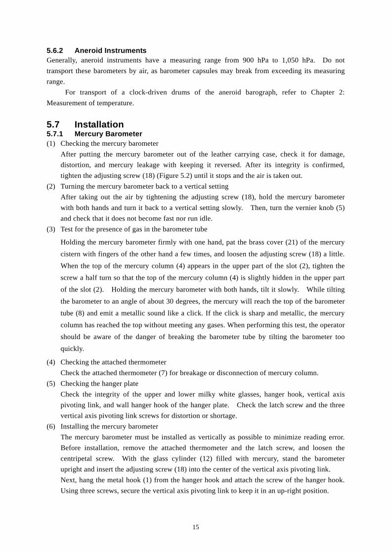
Repair frame
Polyethylene pat
18
entrance of air bubbles after cleaning.
After filling the glass tube with mercury, remove the
barometer from the hanger plate and turn it upside down.
Use cleaning tools free of oil, moisture and acid to prevent
amalgamation.
During disassembly and cleaning, it is important to remember the feeling of the
tightening of the screw to reassemble the components as before.
Tools required for disassembly and cleaning are listed in the attached table.
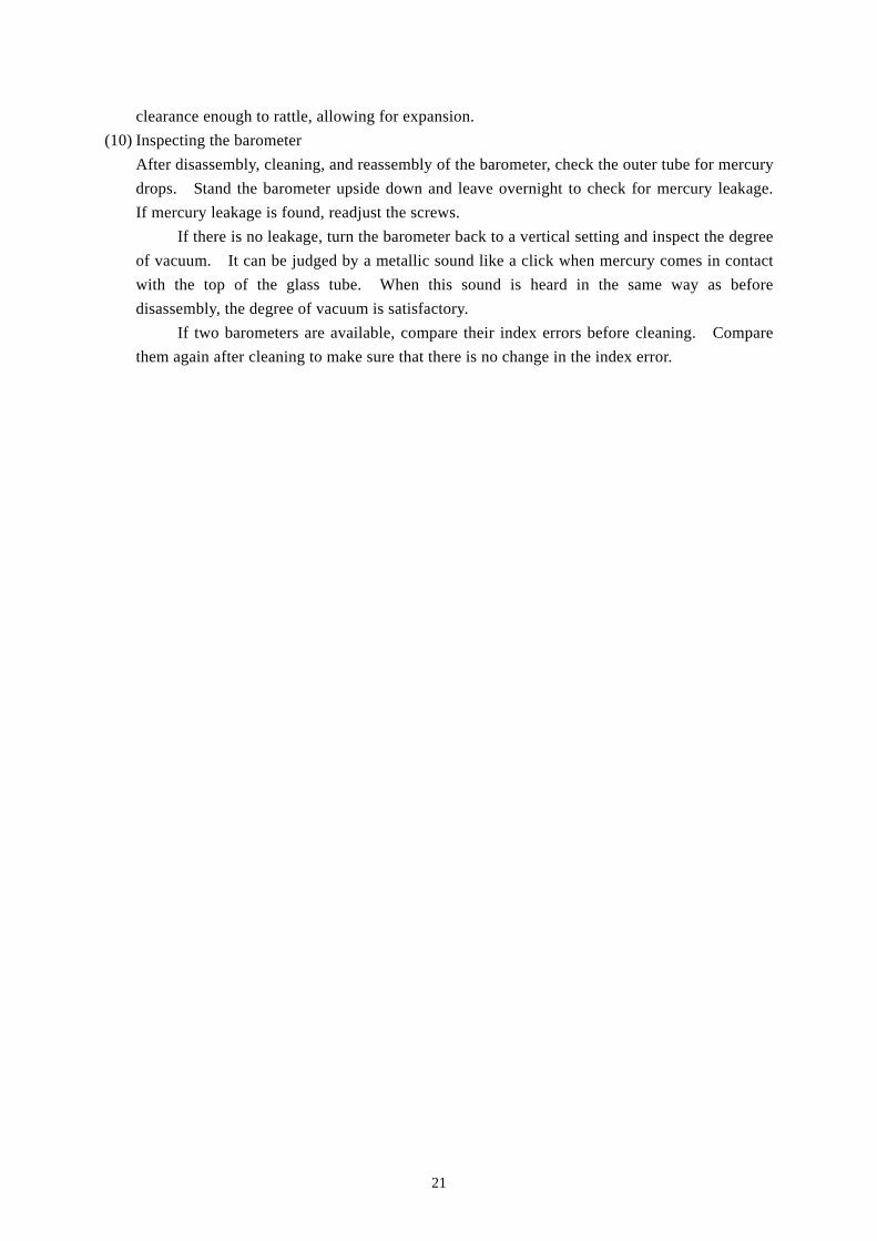
(2) Disassembling the mercury cistern
In the same way for transporting the barometer, turn the barometer upside down after the
mercury reaches the top of the glass tube. Install the barometer in the repair frame for
mercury barometer (Figure 5.10). It is recommended to pack the barometer with
polyethylene bag from the scale to barometer tube. Pressing the brass cylinder, turn the screw
under cover (Figure 5.11, b), to the left, to remove.
Pick up the wash-leather bag to check for mercury leakage. If mercury is leaking, press
the wooden base screw bridge with a finger, turn the barometer back to the vertical setting, and
remove the leaking mercury into a beaker. This leakage mercury has been amalgamated and
must not be mixed with mercury in the mercury cistern.
Pressing the upper part of three screws (Figure 5.11, d) with one hand, turn the brass
cylinder (Figure 5.11, c) to the left to remove. If the screw is stiff, tighten it slightly, apply a
small amount of oil, or pat it slightly, before loosening the screw.
Pat the wash-leather bag to remove mercury, and turn the boxwood counterclockwise
(Figure 5.12) to which the wash-leather bag is attached. If the screw is stiff, tighten it with a
rather thick hemp thread (Figure 5.13, a, b) and the other end around the hand (Figure 5.13, c),
and turn the boxwood counterclockwise with the thread. This should be done carefully not to
leakage mercury, as the glass cylinder is filled with mercury (Figure 5.12).
(3) Draining mercury from the mercury cistern
Syringe a small amount of mercury into a beaker. Be careful not to splash the mercury.
Insert a finger into the mercury cistern to feel the opening of the tube (Figure 5.14,b). Plug
the opening with a finger to prevent mercury flowing out of the glass tube. Excess force will
break the tapered part of the glass tube. With the opening of the tube plugged with the middle
finger, lift up the barometer with the other hand, and pour mercury into a beaker slowly
without spilling outside the beaker. After removing the mercury completely, turn the
barometer upside down as before and unplug the opening of the glass tube.
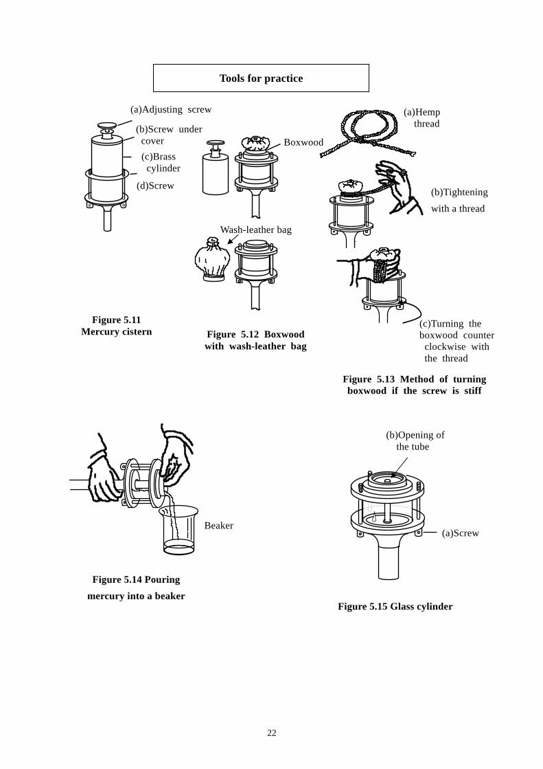
(4) Disassemble the mercury cistern glass cylinder
Loosen and remove three screws (Figure 5.15, a) one by one, feeling the tightening of the
screw. Next, remove the brass metal frame, wooden frame, and glass cylinder (Figure 5.16).
It is recommended to mark the screws and holes to prevent mismatching during the
reassembly. It is also recommended to mark the glass tube seam and gasket positions to
prevent mercury leakage after reassembly.
The leather gaskets attached in the upper and lower parts of the glass tube should not be
removed. When the gaskets are very dirty, however, remove and soften them well. Pinch
Figure 5.10 Repair frame and Polyethylene pat
19
the gasket with a pair of tweezers and immerse it into the beaker filled with filtered mercury to
allow the mercury to adsorb the dirt. Then attach the gaskets during reassembly.
(5) Filtering mercury and cleaning components
For the filtering the mercury, pour the mercury into the strain that stands on a beaker covered
by a thick paper (cross grained paper) (See Figure 5.17).
First, filter mercury with a rough strain, then again with a fine strain. Repeat this twice
or more until no dust is found. Since this process requires a lot of time, this filtering work
should start as soon as the mercury is drained into the beaker.
Wipe the glass cylinder with cleaning paper moistened with alcohol, being careful not to
rub off the marks. Scrape off excess dirt with a cutter, taking care not to damage the glass
cylinder, then polish the surface with a toothbrush and toothpaste. Wipe the glass cylinder
sufficiently to remove moisture.
Wipe the boxwood part (Figure 5.16, c) with the cleaning paper. Wipe the inside of the
wash-leather bag (Figure 5.12, b) with the cleaning paper. Then, put single-filtered mercury
into the bag up to about 1/3, hold the bag with one hand to prevent mercury from splashing,
and rub it with another hand to allow the mercury to adsorb the dirt. Repeat this process until
the dirt in the bag is not found.
Filter the contaminated mercury again and repeat it until it becomes clean.
Wipe dust off the ivory pointer with a brush and the paper softly. Take care not to
move or damage the ivory pointer, as it will affect index error. Wipe dust off the wooden
frame and glass tube with a brush and the cleaning paper.
Some barometers contain mica plates (Figure 5.2, 22) inside the brass cylinders (Figure
5.2, 21). Remove the mica plates carefully and wipe dust off with the cleaning paper or a
brush.
Bubbles often cling to the inlet of the glass tube. Pull them out by inserting a
well-dried iron wire (such as a needle).
(6) Assembling the mercury cistern glass cylinder
Reassemble the glass cylinder in the reverse order of disassembly. Before reassembly, wipe
dust off with clean paper or brush very carefully.
Hold the upper and lower parts of the glass tube, assemble it to the main body. Be
careful not to mix up the upper and lower sides and its orientation or leave fingerprints.
When the gasket comes off, soften and wash it well with mercury before setting it into the
groove.
Place the boxwood (Figure 5.16) on the main body and cover it with the brass metal frame
(Figure 5.16), paying careful attention to the marks and the gaskets.
Attach the three screws (Figure 5.16) to the original positions. Tighten the screws
while rotating the main body and adjusting the balance of screws to each other. Unbalanced
tightening may result in mercury leakage or glass tube breakage.
To clean the assembled mercury cistern (Figure 5.15), pour mercury through the
clearance of the wooden base while filtering so that the mercury adsorbs dirt. To drain the
mercury, plug the opening of the tube (Figure 5.15, b) with a fingertip covered with a
fingerstall and turn the main body upside down. If this is done when the mercury is concave
20
at the opening of the tube, bubbles will enter into the tube. To prevent this, heat the main
body tube with a dryer to allow the mercury to expand before plugging the opening of the tube.
(7) Filling mercury
Pour filtered mercury into the mercury cistern while filtering it again with a fine strain. At
this time, keep the mercury covered (Figure 5.17) to prevent dust from entering.
Mercury is concave at the opening of the tube that has been plugged with a finger. If
mercury is poured while it remains concave, air bubbles will appear at the top of the glass tube
when the barometer is turned back to its vertical setting. These bubbles will deteriorate the
degree of vacuum. Expand the mercury by heating it with drier until it becomes convex at the
opening of the tube. The convex is hardly visible from above, so you need to observe it very
carefully from other angles.
When the mercury becomes convex at the opening of the tube, filter and pour mercury
again until the mercury rises with surface tension just before overflowing. Add refined
mercury, if required.
(8) Assembling the mercury cistern
Wipe dust off the wash-leather bag, and then secure the wooden frame tightly not to allow the
rising mercury to spill. Make sure that the gaskets are properly attached inside the wooden
frame.
Push the screw bridge wood of the wash-leather bag into the mercury cistern with a
fingertip to make sure that mercury is not leaking from the mercury cistern glass cylinder and
the wooden frame (Figure 5.12). If mercury is leaking, stop it by tightening the three screws
of the brass metal frame. If mercury is still leaking, disassemble the gasket and soften it
again.
When tightening the screws of the brass cylinder, take care not to break the screws. If
the screw has been amalgamated due to mercury leakage, ask service personnel for repair.
Tighten the adjusting screw to complete the assembly of the glass cylinder.
At this stage, remove the polyethylene bag attached the barometer.
(9) Cleaning the graduation protective glass tube
After a long time use of a mercury barometer, the graduation protective glass tube (Figure 5.18,
A) may become too dirty to read the vernier clearly. The dirty glass tube should be cleaned at
the same time when the mercury cistern is checked.
To prevent the entry of bubbles, tighten the adjusting screw and turn the barometer back
to a vertical setting. Loosen the adjusting screw by turning two or three turns.
Loosen the glass catch ring holding screw (Figure 5.18, a) under the graduation
protective glass tube, it will go down together with the protective tube. When the latch
holding screw (Figure 5.18, b) comes out of the graduation protective glass tube, remove the
screw. The hanger metal fixture now will come off.
The graduation protective glass tube comes off, too. Clean the inside with paper.
Dust off the graduation and vernier lightly. If there is amalgam on the graduation, the
instrument should be repaired by service personnel.
After cleaning the glass tube, attach the latch holding screw. Lift up the protective tube
catch ring slightly and tighten the holding screw. Assemble the glass tube with some
21
clearance enough to rattle, allowing for expansion.
(10) Inspecting the barometer
After disassembly, cleaning, and reassembly of the barometer, check the outer tube for mercury
drops. Stand the barometer upside down and leave overnight to check for mercury leakage.
If mercury leakage is found, readjust the screws.
If there is no leakage, turn the barometer back to a vertical setting and inspect the degree
of vacuum. It can be judged by a metallic sound like a click when mercury comes in contact
with the top of the glass tube. When this sound is heard in the same way as before
disassembly, the degree of vacuum is satisfactory.
If two barometers are available, compare their index errors before cleaning. Compare
them again after cleaning to make sure that there is no change in the index error.
22
Tools for practice
(a)Adjusting screw
(b)Screw under cover
(c)Brass cylinder
(d)Screw
Figure 5.11 Mercury cistern Figure 5.12 Boxwood
with wash-leather bag
Boxwood
Figure 5.13 Method of turningboxwood if the screw is stiff
Figure 5.14 Pouring
mercury into a beaker Figure 5.15 Glass cylinder
(a) Hemp thread
(b)Tightening
with a thread
(c)Turning the boxwood counter clockwise with the thread
Beaker (a)Screw
(b)Opening of the tube
Wash-leather bag
23
ATTACHED TABLE
Tool and supplies for disassembly and cleaning of a mercury barometer
Tools or supplies Number of tools or
supplies Purposes
Three screws
Boxwood
Brass metal frame
Ivory pointer
Opening of the tube
Boxwood
Glass cylinder
Figure 5.16 Parts of mercury cistern glass cylinder
Figure 5.17 Filtering mercury
Figure 5.18 Protective glass tube
Strain
Thick paper Beaker
(b)Latch holdingscrew
(A) Graduation protective glass tube
(a)Glass catch ringholding screw
24
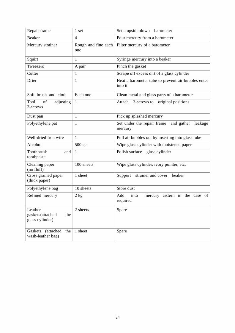
Repair frame 1 set Set a upside-down barometer
Beaker 4 Pour mercury from a barometer
Mercury strainer Rough and fine each one
Filter mercury of a barometer
Squirt 1 Syringe mercury into a beaker
Tweezers A pair Pinch the gasket
Cutter 1 Scrape off excess dirt of a glass cylinder
Drier 1 Heat a barometer tube to prevent air bubbles enter into it
Soft brush and cloth Each one Clean metal and glass parts of a barometer
Tool of adjusting 3-screws
1 Attach 3-screws to original positions
Dust pan 1 Pick up splashed mercury
Polyethylene pat 1 Set under the repair frame and gather leakage mercury
Well-dried Iron wire 1 Pull air bubbles out by inserting into glass tube
Alcohol 500 cc Wipe glass cylinder with moistened paper
Toothbrush and toothpaste
1 Polish surface glass cylinder
Cleaning paper (no fluff)
100 sheets Wipe glass cylinder, ivory pointer, etc.
Cross grained paper (thick paper)
1 sheet Support strainer and cover beaker
Polyethylene bag 10 sheets Store dust
Refined mercury 2 kg Add into mercury cistern in the case of required
Leather gaskets(attached the glass cylinder)
2 sheets Spare
Gaskets (attached the wash-leather bag)
1 sheet Spare