Chapter 5 Lecture - University of Pittsburghpitt.edu/~qiw4/Academic/MEMS0031/Chapter5...
31
Department of Mechanical Engineering Department of Mechanical Engineering Department of Mechanical Engineering Department of Mechanical Engineering Chapter 5 Chapter 5
Transcript of Chapter 5 Lecture - University of Pittsburghpitt.edu/~qiw4/Academic/MEMS0031/Chapter5...
Department of Mechanical EngineeringDepartment of Mechanical EngineeringDepartment of Mechanical EngineeringDepartment of Mechanical Engineering
Chapter 5Chapter 5

Department of Mechanical EngineeringDepartment of Mechanical EngineeringDepartment of Mechanical EngineeringDepartment of Mechanical Engineering
Chapter 5 Source Transformation
By KVL:Vs=iRs + v
By KCL: is=i + v/Rp
Vs/Rs=i + v/Rs
is=Vs/RsRs=Rp
is=i + v/Rp
Two circuits have the same terminal voltage and current

Department of Mechanical EngineeringDepartment of Mechanical EngineeringDepartment of Mechanical EngineeringDepartment of Mechanical Engineering
Chapter 5 Source Transformation

Department of Mechanical EngineeringDepartment of Mechanical EngineeringDepartment of Mechanical EngineeringDepartment of Mechanical Engineering
Chapter 5 Source Transformation
Example 1: Find the values of is and R in two circuits if they are equivalent
R=10 Ωis=12/R=1.2 A

Department of Mechanical EngineeringDepartment of Mechanical EngineeringDepartment of Mechanical EngineeringDepartment of Mechanical Engineering
Chapter 5 Source Transformation
Example 2: Find current i in circuit (a)
i=(5V-1.2V)/(5Ω+12Ω)=0.224A

Department of Mechanical EngineeringDepartment of Mechanical EngineeringDepartment of Mechanical EngineeringDepartment of Mechanical Engineering
Chapter 5 Superposition
Example1:(a) A circuit containing two independent sources. (b) The circuit after the ideal ammeter has been replaced by the equivalent short circuit and a label has been added to indicate the current measured by the ammeter im.
De-activate the voltage sourceDe-activate the current source
i1=6/(3+6)=0.67 Α i2=[3/(3+6)]% 2=0.67 Α im=i1+ i2=1.33 Α

Department of Mechanical EngineeringDepartment of Mechanical EngineeringDepartment of Mechanical EngineeringDepartment of Mechanical Engineering
Chapter 5 Superposition
Example2: a) A circuit containing two independent sources. (b) The circuit after the ideal voltmeter has been replaced by the equivalent open circuit and a label has been added to indicate the voltage measured by the voltmeter vm.
With only the voltage source
With only the current source
Department of Mechanical EngineeringDepartment of Mechanical EngineeringDepartment of Mechanical EngineeringDepartment of Mechanical Engineering
Chapter 5 Superposition
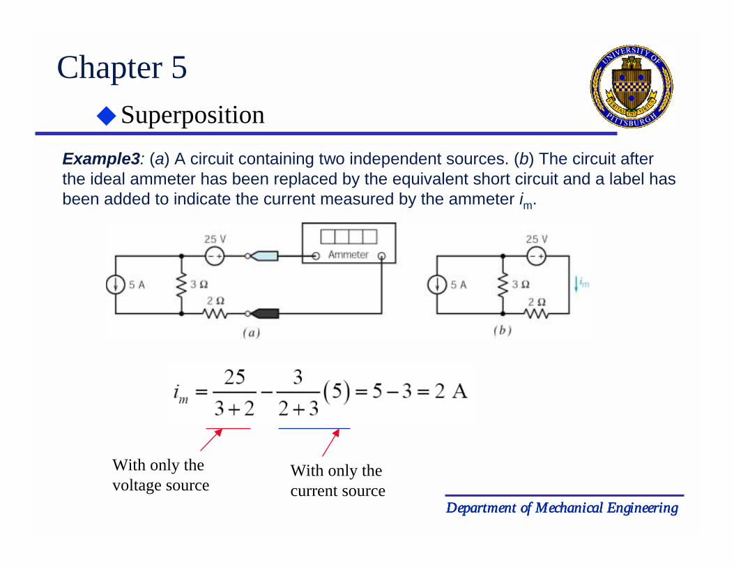
Example3: (a) A circuit containing two independent sources. (b) The circuit after the ideal ammeter has been replaced by the equivalent short circuit and a label has been added to indicate the current measured by the ammeter im.
With only the voltage source
With only the current source

Department of Mechanical EngineeringDepartment of Mechanical EngineeringDepartment of Mechanical EngineeringDepartment of Mechanical Engineering
Chapter 5 Superposition
Example4: (a) A circuit containing two independent sources. (b) The circuit after the ideal voltmeter has been replaced by the equivalent open circuit and a label has been added to indicate the voltage measured by the voltmeter vm.
With only the voltage source
With only the current source
Department of Mechanical EngineeringDepartment of Mechanical EngineeringDepartment of Mechanical EngineeringDepartment of Mechanical Engineering
Chapter 5 Superposition
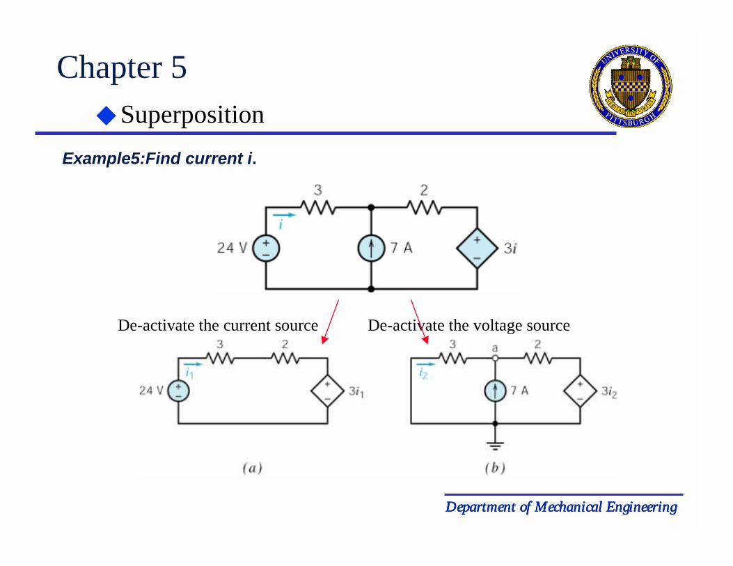
Example5:Find current i.
De-activate the voltage sourceDe-activate the current source

Department of Mechanical EngineeringDepartment of Mechanical EngineeringDepartment of Mechanical EngineeringDepartment of Mechanical Engineering
Chapter 5 Superposition
Example5: Find current i.
For circuit (a): by KVL, we have
24-(3+2)i1-3i1=0
Then i1=3 (A)
For circuit (b): we use node voltage analysis at node a
-i2 –7+ (va-3i2)/2=0For 3Ω resistor, we have
-i2=va/3
Then i2=-7/4i=i1 +i2 =1.25 (A)

Department of Mechanical EngineeringDepartment of Mechanical EngineeringDepartment of Mechanical EngineeringDepartment of Mechanical Engineering
Chapter 5 Thévenin’s Theorem
(a) A circuit partitioned into two parts: circuit A and circuit B. (b) Replacing circuit A by its Thévenin equivalent circuit.
A: Driving circuitB: Load

Department of Mechanical EngineeringDepartment of Mechanical EngineeringDepartment of Mechanical EngineeringDepartment of Mechanical Engineering
Chapter 5 Thévenin’s Theorem
The Thévenin equivalent circuit involves three parameters:(a) the open-circuit voltage, voc, (b) the short-circuit current isc, and (c) the Thévenin resistance, Rt.
voc=Rt isc

Department of Mechanical EngineeringDepartment of Mechanical EngineeringDepartment of Mechanical EngineeringDepartment of Mechanical Engineering
Chapter 5 Thévenin’s Theorem
(a) The Thévenin resistance, Rt, (b) A method for measuring or calculating the Thévenin
resistance, Rt.
Rt=vt/it
Department of Mechanical EngineeringDepartment of Mechanical EngineeringDepartment of Mechanical EngineeringDepartment of Mechanical Engineering
Chapter 5 Thévenin’s Theorem
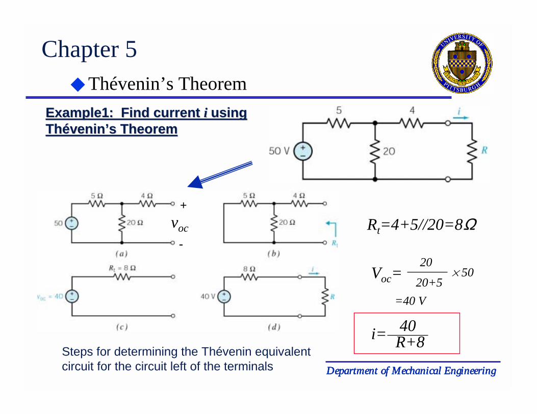
Example1: Find current Example1: Find current ii usingusingThévenin’sThévenin’s TheoremTheorem
Steps for determining the Thévenin equivalent circuit for the circuit left of the terminals
Rt=4+5//20=8Ωvoc
+
-
Voc=20
20+5% 50
=40 V
40i= R+8
Department of Mechanical EngineeringDepartment of Mechanical EngineeringDepartment of Mechanical EngineeringDepartment of Mechanical Engineering
Chapter 5 Thévenin’s Theorem
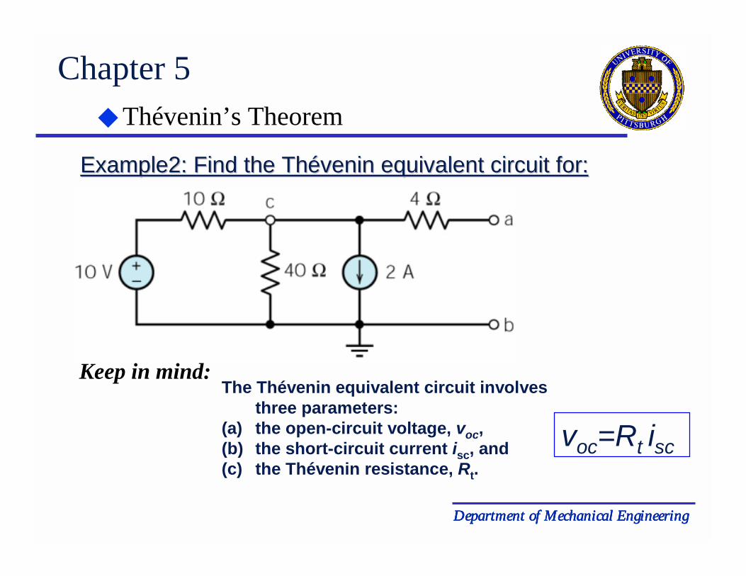
The Thévenin equivalent circuit involves three parameters:
(a) the open-circuit voltage, voc, (b) the short-circuit current isc, and (c) the Thévenin resistance, Rt.
Example2: Find the Example2: Find the ThThééveninvenin equivalent circuit for:equivalent circuit for:
Keep in mind:
voc=Rt isc

Department of Mechanical EngineeringDepartment of Mechanical EngineeringDepartment of Mechanical EngineeringDepartment of Mechanical Engineering
Chapter 5 Thévenin’s Theorem
First, find Rt:
Rt =10//40 + 4=12Ω
Circuit reduction by de-activate all ideal sourcesThen find the equivalent resistant

Department of Mechanical EngineeringDepartment of Mechanical EngineeringDepartment of Mechanical EngineeringDepartment of Mechanical Engineering
Chapter 5 Thévenin’s Theorem
Then, find voc:
voc
+
-Using Node voltage mothod to find vc, since 1-b is open circuit, no voltage drop for 4Ω resistor, voc= vc
vc -1010
+ 40vc + 2=0
Solve for vc
vc =-8V

Department of Mechanical EngineeringDepartment of Mechanical EngineeringDepartment of Mechanical EngineeringDepartment of Mechanical Engineering
Chapter 5 Thévenin’s Theorem
For circuit with dependent sources, we can not directly obtain the Rt from simple circuit reduction.
The procedure to get Rt :• Find open circuit voltage voc, • Find the short-circuit current isc, Rt =
voc
iscExample 3: Find the Example 3: Find the Thévenin’s Thévenin’s equivalent circuit for the following circuit: equivalent circuit for the following circuit:

Department of Mechanical EngineeringDepartment of Mechanical EngineeringDepartment of Mechanical EngineeringDepartment of Mechanical Engineering
Chapter 5 Thévenin’s Theorem
First, find open circuit voltage Voc
Voc
For the left loop, apply KVL:
20-6i+2i-6i=0
i=2 (A)
Voc =6i=12 (V)
Department of Mechanical EngineeringDepartment of Mechanical EngineeringDepartment of Mechanical EngineeringDepartment of Mechanical Engineering
Chapter 5 Thévenin’s Theorem
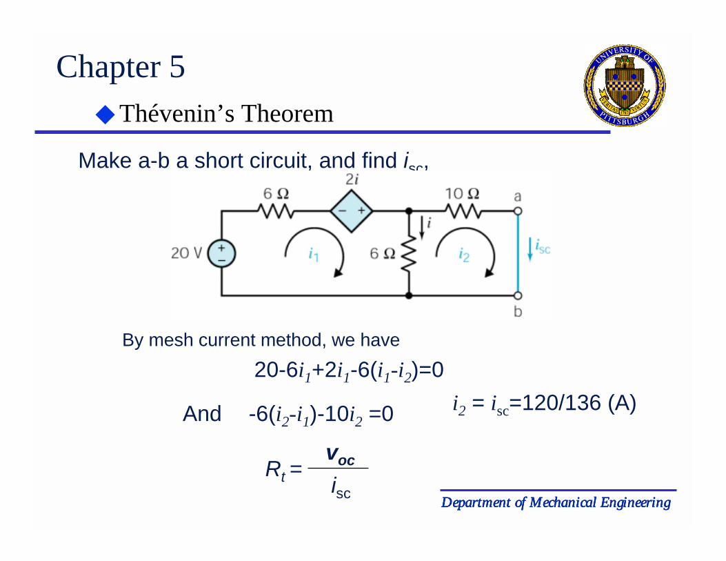
Make a-b a short circuit, and find isc,
Rt =voc
isc
By mesh current method, we have
20-6i1+2i1-6(i1-i2)=0
And -6(i2-i1)-10i2 =0 i2 = isc=120/136 (A)
Department of Mechanical EngineeringDepartment of Mechanical EngineeringDepartment of Mechanical EngineeringDepartment of Mechanical Engineering
Chapter 5 Thévenin’s Theorem
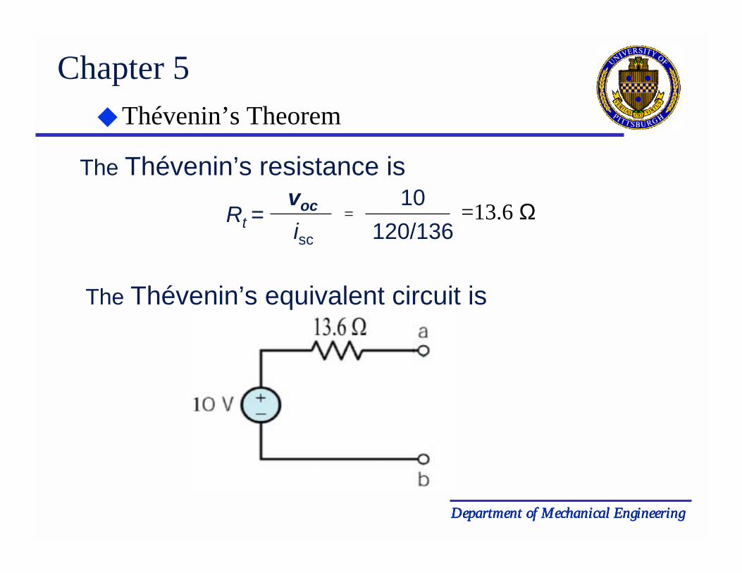
The Thévenin’s resistance is
Rt =voc
isc
=120/136
10 =13.6 Ω
The Thévenin’s equivalent circuit is

Department of Mechanical EngineeringDepartment of Mechanical EngineeringDepartment of Mechanical EngineeringDepartment of Mechanical Engineering
Chapter 5 Norton’s equivalent Circuit
(a) A circuit partitioned into two parts: circuit A and circuit B. (b) Replacing circuit A by its Norton equivalent circuit.
Norton equivalent is simply the source transformation of the Norton equivalent is simply the source transformation of the ThéveninThévenin equivalentequivalent

Department of Mechanical EngineeringDepartment of Mechanical EngineeringDepartment of Mechanical EngineeringDepartment of Mechanical Engineering
Chapter 5 Norton’s equivalent Circuit
Example1: Find the Norton Equivalent Circuit for
Rn =6x126+12
= 4 kΩ
Find Rn by replacing the voltage source with a short circuit
Department of Mechanical EngineeringDepartment of Mechanical EngineeringDepartment of Mechanical EngineeringDepartment of Mechanical Engineering
Chapter 5 Norton’s equivalent Circuit
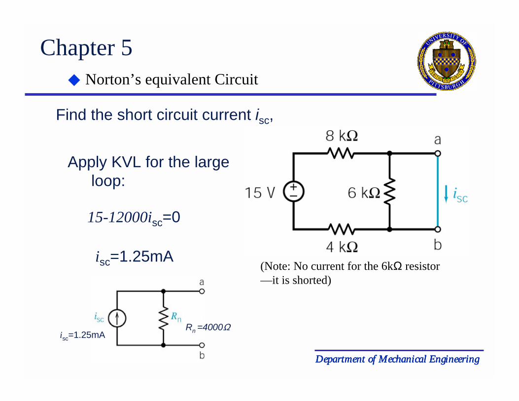
Find the short circuit current isc,
Apply KVL for the large loop:
15-12000isc=0
(Note: No current for the 6kΩ resistor—it is shorted)
isc=1.25mA
isc=1.25mARn =4000Ω

Department of Mechanical EngineeringDepartment of Mechanical EngineeringDepartment of Mechanical EngineeringDepartment of Mechanical Engineering
Chapter 5
First, find the open circuit voltage:
Norton’s equivalent Circuit
Example2: Find the Norton Equivalent Circuit for
vocApply KVL for the close loop:
12+6ia-2ia=0
ia=-3(A) voc=2ia=-6(V)
Department of Mechanical EngineeringDepartment of Mechanical EngineeringDepartment of Mechanical EngineeringDepartment of Mechanical Engineering
Chapter 5
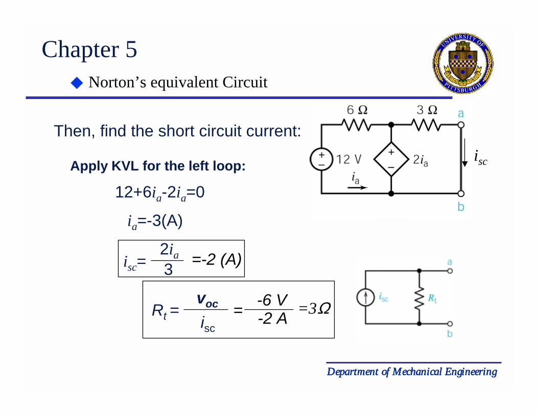
Then, find the short circuit current:
Norton’s equivalent Circuit
iscApply KVL for the left loop:
12+6ia-2ia=0
ia=-3(A)
isc=2ia3 =-2 (A)
Rt =voc
isc= -6 V
-2 A =3Ω

Department of Mechanical EngineeringDepartment of Mechanical EngineeringDepartment of Mechanical EngineeringDepartment of Mechanical Engineering
Chapter 5
For a circuit A and load resistor RL
Maximum Power Transfer
Circuit A contains resistors and independent and dependent sources.
The Thévenin equivalent is substituted for circuit A. Here we use vs for theThévenin source voltage.
Department of Mechanical EngineeringDepartment of Mechanical EngineeringDepartment of Mechanical EngineeringDepartment of Mechanical Engineering
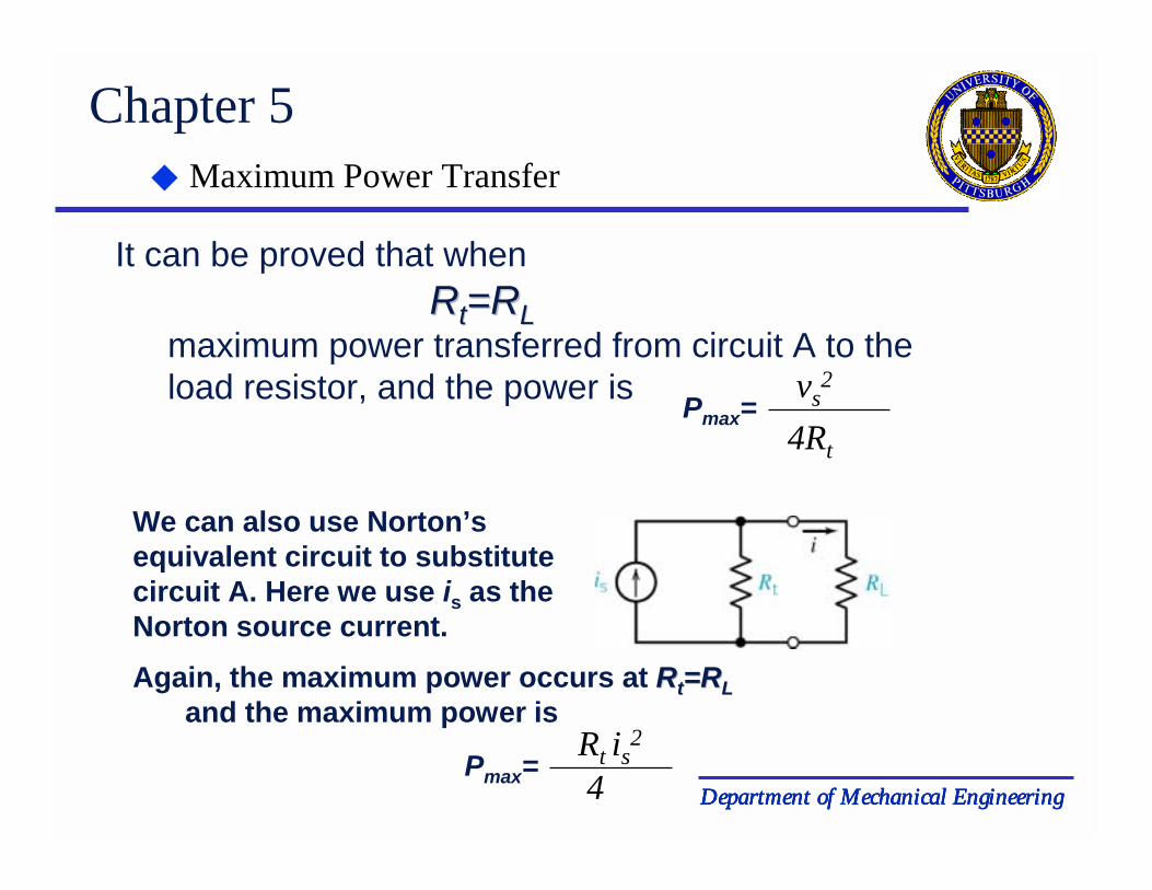
Chapter 5
It can be proved that when RRtt=R=RLL
maximum power transferred from circuit A to the load resistor, and the power is
Maximum Power Transfer
We can also use Norton’s equivalent circuit to substitute circuit A. Here we use is as the Norton source current.
Pmax=vs
2
4Rt
Again, the maximum power occurs at RRtt=R=RLLand the maximum power is
Pmax=Rt is
2
4

Department of Mechanical EngineeringDepartment of Mechanical EngineeringDepartment of Mechanical EngineeringDepartment of Mechanical Engineering
Chapter 5
Example: Find the Load RL that result in maximum power delivered to the load. Also determine Pmax
First, we use the circuit (b) to obtain theThévenin equivalent circuit.
Maximum Power Transfer
Find the open circuit voltage voc. Apply KVL to the close loop:
voc6-6i+2vab-4i=0
And vab=4i
i=3Avoc= vab= 12 (V)

Department of Mechanical EngineeringDepartment of Mechanical EngineeringDepartment of Mechanical EngineeringDepartment of Mechanical Engineering
Chapter 5 Maximum Power Transfer
Find the short circuit current for circuit (c), isc.
6-6isc+2vab=0
isc=1 (A)
Since ab is short, vab=0.Apply KVL to the close loop:
Rt =voc
isc
Find the equivalent resistance:
=12 Ω
RRLL==RRtt=12 =12 ΩΩΩΩΩΩΩΩ Pmax=voc
2
4Rt=
122
4(12)=3 W