
Chapter 5 - Defects and Non-stoichiometrymichael.lufaso/chem4627/ch5_solid_state.pdf$VVXPLQJ '+ V î...
42
1 Chapter 5: Defects and Non- stoichiometry Perfect Crystal Extended Defects Point Defects Extrinsic Intrinsic Grain Boundaries Dislocations
Transcript of Chapter 5 - Defects and Non-stoichiometrymichael.lufaso/chem4627/ch5_solid_state.pdf$VVXPLQJ '+ V î...

1
Chapter 5: Defects and Non-
stoichiometry
Perfect Crystal
Extended Defects Point Defects
ExtrinsicIntrinsicGrain Boundaries
Dislocations

2
Point Defect - Intrinsic
Schottky Frenkel
interstitial cationanion vacancycation vacancy
Na+ + Cl- Vna + VCl Ag+ VAg+ Ag+interstitial
Anion Frenkel defect in fluorite
Example fluorites include CaF2, SrF2, PbF2, ThO2, UO2, ZrO2
Cation Frenkel defects are common because of the typically smaller size of a cation compared to an anion.
•However, anions in the fluorite structure have a lower electrical charge than the cations and don’t find it as difficult to move nearer each other.
•The fluorite structure ccpcations with all tetrahedral holes occupied by the anions –thus all octahedral holes are unoccupied.

3
Concentration of defects
•At equilibrium, the overall change in free energy of the crystal due to the defect formation is zero according to:
DG = DH – TDS
D
kT
HNn s
s 2exp
where ns is the number of Schottky defects per unit volume, at T K, in a crystal with N cations and N anion sites per unit cell volume, and DHs is the enthalpy required to form one defect.
At any temperature, there will always be an equilibrium population of defects. The number of defects (for an MX crystal) is given by:
Energy is required to form a defect (endothermic process)
•Although there is a cost in energy, there is a gain in entropy in the formation of a defect.
Concentration of defects, cont.
Estimate the configurational entropy, the change of entropy due to the vibrations of atoms around the defects and the arrangement of defects, using methods of statistical mechanics.
•If the number of Schottky defects is ns per unit volume at T K, then there are ns cation vacancies and ns anion vacancies in a crystal containing N possible cation sites and N possible anion sites.
•The Boltzmann formula tells us that the entropy of such a system is:
S = klnW
where W is the number of ways of distributing ns defects over Npossible sites at random, and k is the Boltzmann constant (1.38x10⁻²³
J/K)
•Probability theory shows that W is given by:
!)!(
!
nnN
NW
N! is ‘factorial N’. N×(N-1)×(N-2)…×1
4
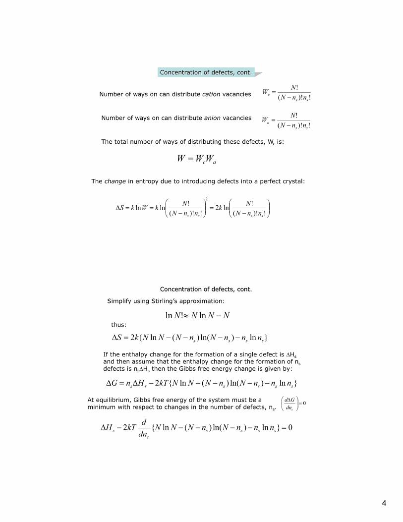
Concentration of defects, cont.
!)!(
!
ssc nnN
NW
Number of ways on can distribute cation vacancies
!)!(
!
ssa nnN
NW
Number of ways on can distribute anion vacancies
The total number of ways of distributing these defects, W, is:
acWWW
The change in entropy due to introducing defects into a perfect crystal:
D!)!(
!ln2
!)!(
!lnln
2
ssss nnN
Nk
nnN
NkWkS
Simplify using Stirling’s approximation:
NNNN ln!ln
Concentration of defects, cont.
}ln)ln()(ln{2 ssss nnnNnNNNkS D
thus:
If the enthalpy change for the formation of a single defect is DHsand then assume that the enthalpy change for the formation of nsdefects is nsDHs then the Gibbs free energy change is given by:
}ln)ln()(ln{2 ssssss nnnNnNNNkTHnG DD
At equilibrium, Gibbs free energy of the system must be a minimum with respect to changes in the number of defects, ns.
0
D
sdn
Gd
0}ln)ln()(ln{2 D sssss
s nnnNnNNNdn
dkTH
5
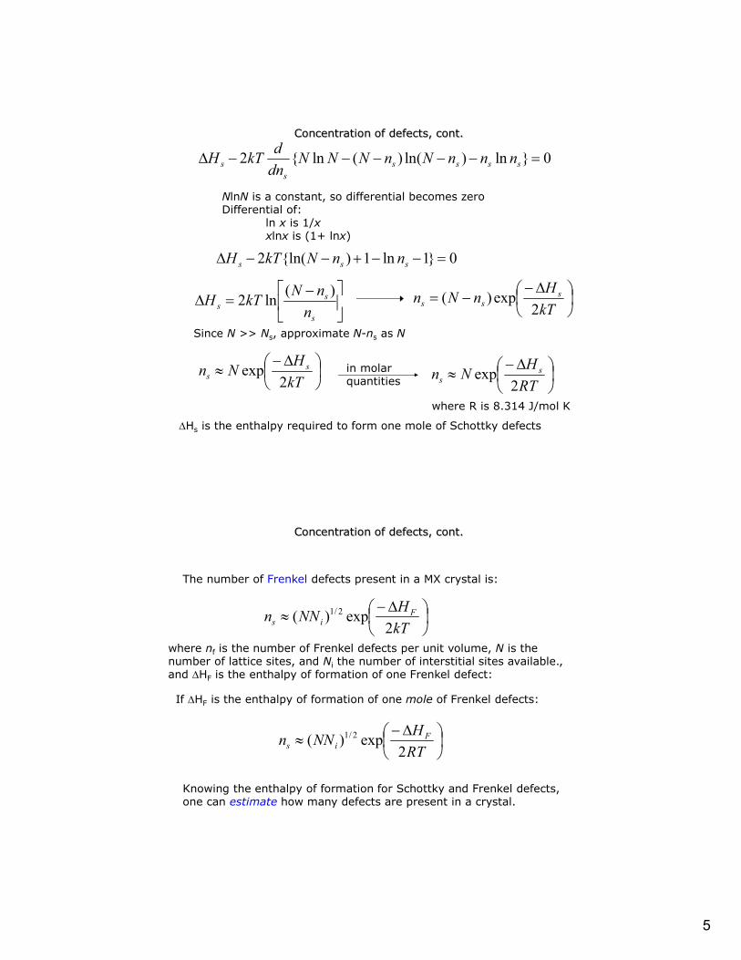
Concentration of defects, cont.
0}ln)ln()(ln{2 D sssss
s nnnNnNNNdn
dkTH
NlnN is a constant, so differential becomes zeroDifferential of:
ln x is 1/xxlnx is (1+ lnx)
0}1ln1){ln(2 D sss nnNkTH
D
s
ss n
nNkTH
)(ln2
D
kT
HnNn sss 2
exp)(
Since N >> Ns, approximate N-ns as N
D
kT
HNn s
s 2exp in molar
quantities
D
RT
HNn s
s 2exp
where R is 8.314 J/mol K
DHs is the enthalpy required to form one mole of Schottky defects
Concentration of defects, cont.
D
kT
HNNn F
is 2exp)( 2/1
The number of Frenkel defects present in a MX crystal is:
where nf is the number of Frenkel defects per unit volume, N is the number of lattice sites, and Ni the number of interstitial sites available., and DHF is the enthalpy of formation of one Frenkel defect:
D
RT
HNNn F
is 2exp)( 2/1
If DHF is the enthalpy of formation of one mole of Frenkel defects:
Knowing the enthalpy of formation for Schottky and Frenkel defects, one can estimate how many defects are present in a crystal.
6
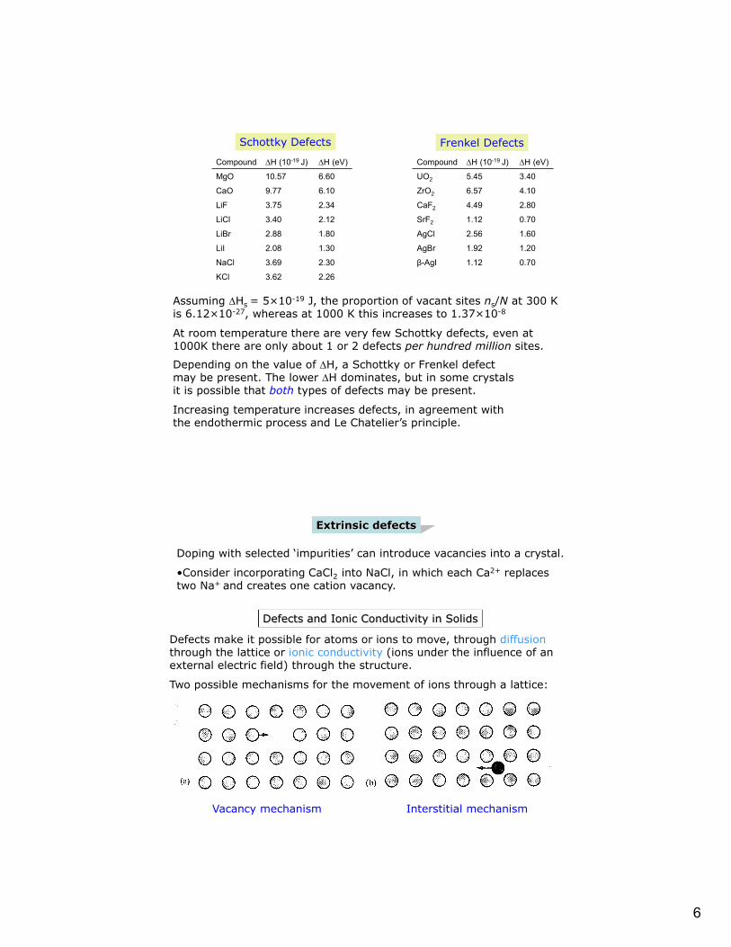
Assuming DHs = 5×10-19 J, the proportion of vacant sites ns/N at 300 K is 6.12×10⁻²⁷, whereas at 1000 K this increases to 1.37×10⁻⁸
At room temperature there are very few Schottky defects, even at 1000K there are only about 1 or 2 defects per hundred million sites.
Depending on the value of DH, a Schottky or Frenkel defect may be present. The lower DH dominates, but in some crystals it is possible that both types of defects may be present.
Increasing temperature increases defects, in agreement with the endothermic process and Le Chatelier’s principle.
Compound DH (10-19 J) DH (eV)
MgO 10.57 6.60
CaO 9.77 6.10
LiF 3.75 2.34
LiCl 3.40 2.12
LiBr 2.88 1.80
LiI 2.08 1.30
NaCl 3.69 2.30
KCl 3.62 2.26
Compound DH (10-19 J) DH (eV)
UO2 5.45 3.40
ZrO2 6.57 4.10
CaF2 4.49 2.80
SrF2 1.12 0.70
AgCl 2.56 1.60
AgBr 1.92 1.20
β-AgI 1.12 0.70
Schottky Defects Frenkel Defects
Extrinsic defects
Doping with selected ‘impurities’ can introduce vacancies into a crystal.
•Consider incorporating CaCl2 into NaCl, in which each Ca2+ replaces two Na+ and creates one cation vacancy.
Defects and Ionic Conductivity in Solids
Defects make it possible for atoms or ions to move, through diffusionthrough the lattice or ionic conductivity (ions under the influence of an external electric field) through the structure.
Two possible mechanisms for the movement of ions through a lattice:
Vacancy mechanism Interstitial mechanism

7
Ion Migration (Schottky defects)
Na+ ions move, but meet resistance in the crystal structure
Na
NaNa
Cl
Cl
ClCl
The Frenkel defects in AgCl can migrate via two mechanisms.
Ag
Ag
Ag
Cl
Cl
Cl
Cl
Ag2
Ag1
Ag
Ag
Cl
Cl
Ag
Ag
Ag
Cl
Cl
Cl
Cl
Ag2
Ag1
Ag
Ag
Cl
Cl
Ag
Ag
Ag
Cl
Cl
Cl
Cl
Ag1
Ag2
Ag
Ag
Cl
Cl
Ag
Ag
Ag
Cl
Cl
Cl
Cl
Ag2
Ag1
Ag
Ag
Cl
Cl
Direct Interstitial Jump
Interstitialcy Mechanism
Ion Migration (Frenkel Defects)

8
The energy required to make the jump, Ea, is the activation energy.
Ionic Conductivity
Ionic Conductivity, σ, is defined the same as electrical conductivity:
σ = nZemwhere n is the number of charge carriers per unit volume, Ze is the charge (e = 1.602189×10⁻¹⁹ C), and m is the mobility, which is a measure of the drift velocity in a constant electric field.
Material Conductivity / (S m-1)
Ionic Conductors Ionic crystals <10-16 – 10-2
Solid electrolytes 10-1 – 103
Strong (liquid) electrolytes 10-1 – 103
Electronic conductors Metals 103 – 107
Semiconductors 10-3 – 104
Insulators <10-10

9
Ionic Conductivity
If the external field is small (up to 300 V cm-1), a temperature dependence of 1/T is present in the pre exponential factor.
An expression for the variation of ionic conductivity:
T
E
Taexp0
The temperature dependence of the mobility of the ions can be expressed by an Arrhenius equation.
kT
Eaexpm
kT
Eaexp0mm where m0 is a proportionality constant known as the pre-exponential factor
or
m0 depends on the attempt frequency (frequency of vibration of the lattice 1012-1013 Hz), distance moved by ion, and the size of the external field.
The term σ0 contains n and Ze as well as the attempt frequency and jump distance. Taking logs…
T
ET a
0lnln
Plotting lnσT vs 1/T should produce a straight line with a slope of –Ea.
lnσ vs 1/T is also used
Conductivities of Solid Electrolytes vs Temperature
NaCl
10
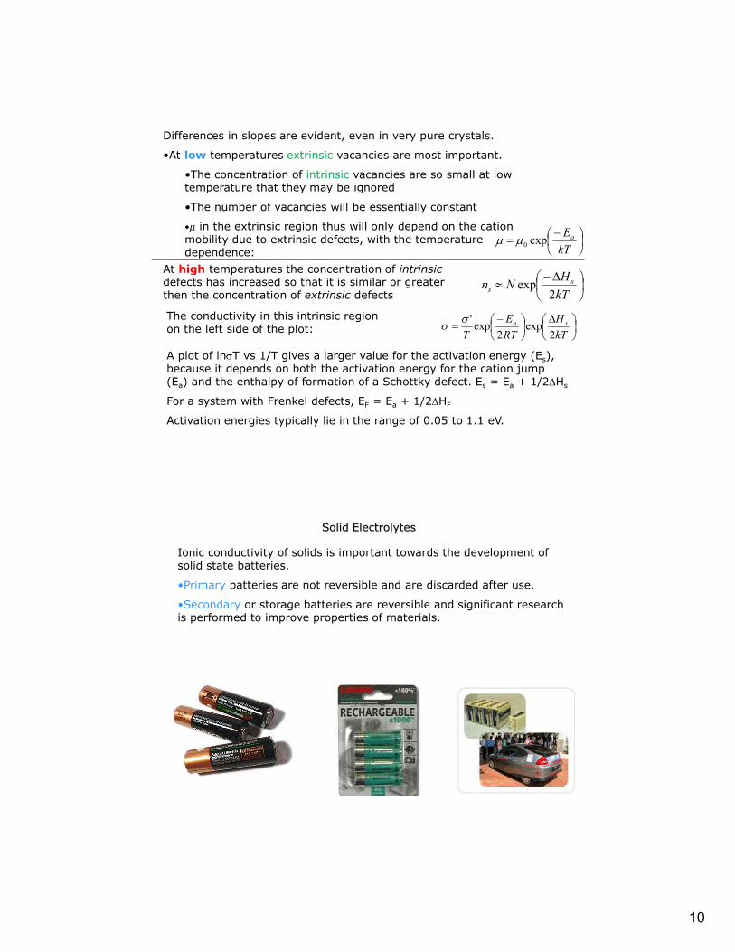
Differences in slopes are evident, even in very pure crystals.
•At low temperatures extrinsic vacancies are most important.
•The concentration of intrinsic vacancies are so small at low temperature that they may be ignored
•The number of vacancies will be essentially constant
• in the extrinsic region thus will only depend on the cation mobility due to extrinsic defects, with the temperature dependence:
kT
Eaexp0mm
At high temperatures the concentration of intrinsicdefects has increased so that it is similar or greater then the concentration of extrinsic defects
D
kT
HNn s
s 2exp
The conductivity in this intrinsic region on the left side of the plot:
D
kT
H
RT
E
Tsa
2exp
2exp
'
A plot of lnT vs 1/T gives a larger value for the activation energy (Es), because it depends on both the activation energy for the cation jump (Ea) and the enthalpy of formation of a Schottky defect. Es = Ea + 1/2DHs
For a system with Frenkel defects, EF = Ea + 1/2DHF
Activation energies typically lie in the range of 0.05 to 1.1 eV.
Solid Electrolytes
Ionic conductivity of solids is important towards the development of solid state batteries.
•Primary batteries are not reversible and are discarded after use.
•Secondary or storage batteries are reversible and significant research is performed to improve properties of materials.
11
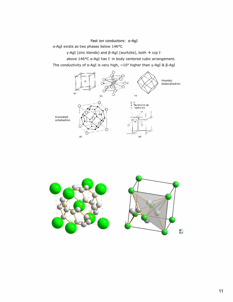
α-AgI exists as two phases below 146°C
γ-AgI (zinc blende) and β-AgI (wurtzite), both ccp I-
above 146°C α-AgI has I- in body centered cubic arrangement.
The conductivity of α-AgI is very high, ~104 higher than γ-AgI & β-AgI
Fast ion conductors: α-AgI
rhombic dodecahedron
truncated octahedron
12
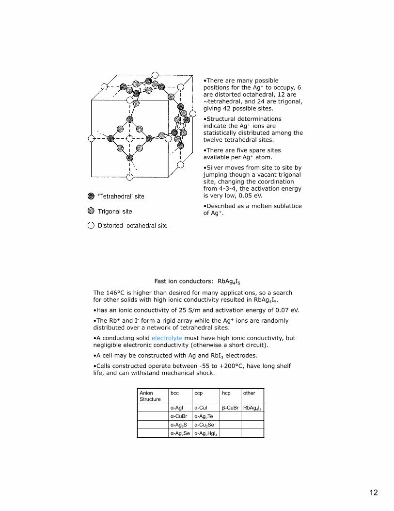
•There are many possible positions for the Ag+ to occupy, 6 are distorted octahedral, 12 are ~tetrahedral, and 24 are trigonal, giving 42 possible sites.
•Structural determinations indicate the Ag+ ions are statistically distributed among the twelve tetrahedral sites.
•There are five spare sites available per Ag+ atom.
•Silver moves from site to site by jumping though a vacant trigonal site, changing the coordination from 4-3-4, the activation energy is very low, 0.05 eV.
•Described as a molten sublattice of Ag+.
Fast ion conductors: RbAg4I5
The 146°C is higher than desired for many applications, so a search for other solids with high ionic conductivity resulted in RbAg4I5.
•Has an ionic conductivity of 25 S/m and activation energy of 0.07 eV.
•The Rb+ and I- form a rigid array while the Ag+ ions are randomly distributed over a network of tetrahedral sites.
•A conducting solid electrolyte must have high ionic conductivity, but negligible electronic conductivity (otherwise a short circuit).
•A cell may be constructed with Ag and RbI3 electrodes.
•Cells constructed operate between -55 to +200°C, have long shelf life, and can withstand mechanical shock.
Anion Structure
bcc ccp hcp other
α-AgI α-CuI β-CuBr RbAg4I5
α-CuBr α-Ag2Te
α-Ag2S α-Cu2Se
α-Ag2Se α-Ag2HgI4
13
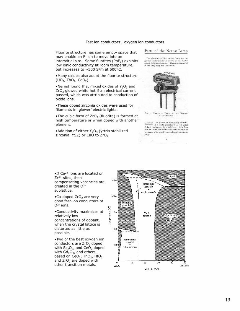
Fast ion conductors: oxygen ion conductors
Fluorite structure has some empty space that may enable an F- ion to move into an interstitial site. Some fluorites (PbF2) exhibits low ionic conductivity at room temperature, but increases to ~500 S/m at 500°C.
•Many oxides also adopt the fluorite structure (UO2, ThO2, CeO2)
•Nernst found that mixed oxides of Y2O3 and ZrO2 glowed white hot if an electrical current passed, which was attributed to conduction of oxide ions.
•These doped zirconia oxides were used for filaments in ‘glower’ electric lights.
•The cubic form of ZrO2 (fluorite) is formed at high temperature or when doped with another element.
•Addition of either Y2O3 (yttria stabilized zirconia, YSZ) or CaO to ZrO2
•If Ca2+ ions are located on Zr4+ sites, then compensating vacancies are created in the O2-
sublattice.
•Ca-doped ZrO2 are very good fast-ion conductors of O2- ions.
•Conductivity maximizes at relatively low concentrations of dopant, when the crystal lattice is distorted as little as possible.
•Two of the best oxygen ion conductors are ZrO2 doped with Sc2O3, and CeO2 doped with Gd2O3, and others based on CeO2, ThO2, HfO2, and ZrO2 are doped with other transition metals.

14
Perovskite:
Materials based on the perovskite lanthanum gallate, LaGaO3, doped with Sr2+ and Mg2+, produce La1-xSrxGa1-yMgyO3-d (LSGM).
•Has similar conductivities to zirconias, but at a lower operating temperature.
•For a cathode material in a solid oxide fuel cell, a material is needed that can conduct both ions and electrons. The Sr2+
doped LaMnO3 (LSM) and LaCrO3 (Sr) have both these properties.
LAMOX:
•Materials based on La2Mo2O9 has high conductivity above 600°C, but tend to be susceptible to reduction by hydrogen.
BIMEVOX:
•Materials based on Bi2O3 have high conductivity above 600°C
Apatite:
•Structure based on La10-xM6O26+y (M = Si, Ge) conduct well at high temperatures.
Oxygen ion conductors: Other
•β-alumina is a series of compounds that exhibit fast-ion conducting properties.
•Parent compound is sodium β-alumina, NaAl11O17
•General formula is M2O-nX2O3, where n can range from 5 to 11 and M is a monovalent cation (alkali metal)+, Cu+, Ag+, NH4
+, and X is a trivalent cation Al3+, Ga3+, or Fe3+.
•High conductivity of the compound is related to the crystal structure.
•Close-packed layers of oxide ions, but in every fifth layer three-fourths of the oxygens are missing. The four close packed layers contain Al3+ ions in both octahedral and tetrahedral holes. The Na+ are found in the fifth oxide layer [B(ABCA) C (ACBA) B]. Na+ ions move in the conduction plane.
Fast-ion conductors: sodium ion conductors
15
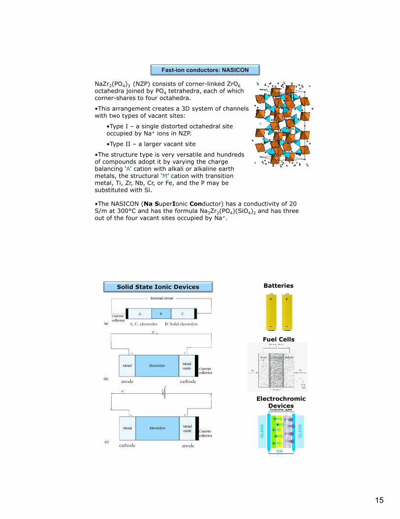
Fast-ion conductors: NASICON
NaZr2(PO4)3 (NZP) consists of corner-linked ZrO6octahedra joined by PO4 tetrahedra, each of which corner-shares to four octahedra.
•This arrangement creates a 3D system of channels with two types of vacant sites:
•Type I – a single distorted octahedral site occupied by Na+ ions in NZP.
•Type II – a larger vacant site
•The structure type is very versatile and hundreds of compounds adopt it by varying the charge balancing ‘A’ cation with alkali or alkaline earth metals, the structural ‘M’ cation with transition metal, Ti, Zr, Nb, Cr, or Fe, and the P may be substituted with Si.
•The NASICON (Na SuperIonic Conductor) has a conductivity of 20 S/m at 300°C and has the formula Na3Zr2(PO4)(SiO4)2 and has three out of the four vacant sites occupied by Na+.
Batteries
Fuel Cells
Electrochromic Devices
Solid State Ionic Devices
cathode anode
cathodeanode
A, C: electrodes B: Solid electrolyte
16
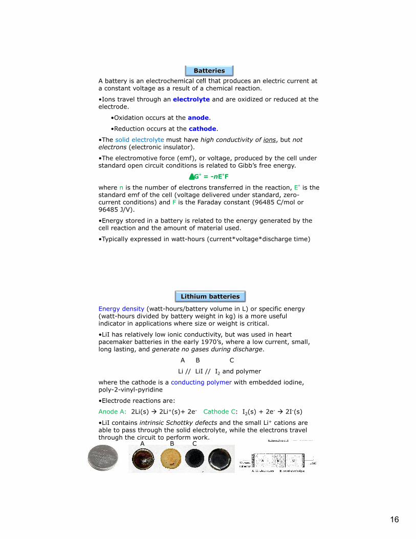
A battery is an electrochemical cell that produces an electric current at a constant voltage as a result of a chemical reaction.
•Ions travel through an electrolyte and are oxidized or reduced at the electrode.
•Oxidation occurs at the anode.
•Reduction occurs at the cathode.
•The solid electrolyte must have high conductivity of ions, but not electrons (electronic insulator).
•The electromotive force (emf), or voltage, produced by the cell under standard open circuit conditions is related to Gibb’s free energy.
DG° = -nE°F
where n is the number of electrons transferred in the reaction, E° is the standard emf of the cell (voltage delivered under standard, zero-current conditions) and F is the Faraday constant (96485 C/mol or 96485 J/V).
•Energy stored in a battery is related to the energy generated by the cell reaction and the amount of material used.
•Typically expressed in watt-hours (current*voltage*discharge time)
Batteries
Energy density (watt-hours/battery volume in L) or specific energy (watt-hours divided by battery weight in kg) is a more useful indicator in applications where size or weight is critical.
•LiI has relatively low ionic conductivity, but was used in heart pacemaker batteries in the early 1970’s, where a low current, small, long lasting, and generate no gases during discharge.
A B C
Li // LiI // I2 and polymer
where the cathode is a conducting polymer with embedded iodine, poly-2-vinyl-pyridine
•Electrode reactions are:
Anode A: 2Li(s) 2Li+(s)+ 2e- Cathode C: I2(s) + 2e- 2I-(s)
•LiI contains intrinsic Schottky defects and the small Li+ cations are able to pass through the solid electrolyte, while the electrons travel through the circuit to perform work.
CBA
Lithium batteries

17
•Sony developed rechargeable lithium-ion batteries the are able to undergo many charge-discharge cycles.
•The lightweight batteries find use in many applications from mobile phones and laptop computers, etc.
•Driving reaction is that of Li with CoO2 to form an intercalation compound, LixCoO2 and anode is Li in graphitic carbon.
A B C
Li/C // Li+ electrolyte // CoO2
•Electrode reactions are:
Anode A: LixC6(s) xLi++6C + xe-
Cathode C: xLi+ + CoO2(s) + xe- LixCoO2(s)
http://electronics.howstuffworks.com/lithium-ion-battery1.htm
Lithium-ion batteries
18
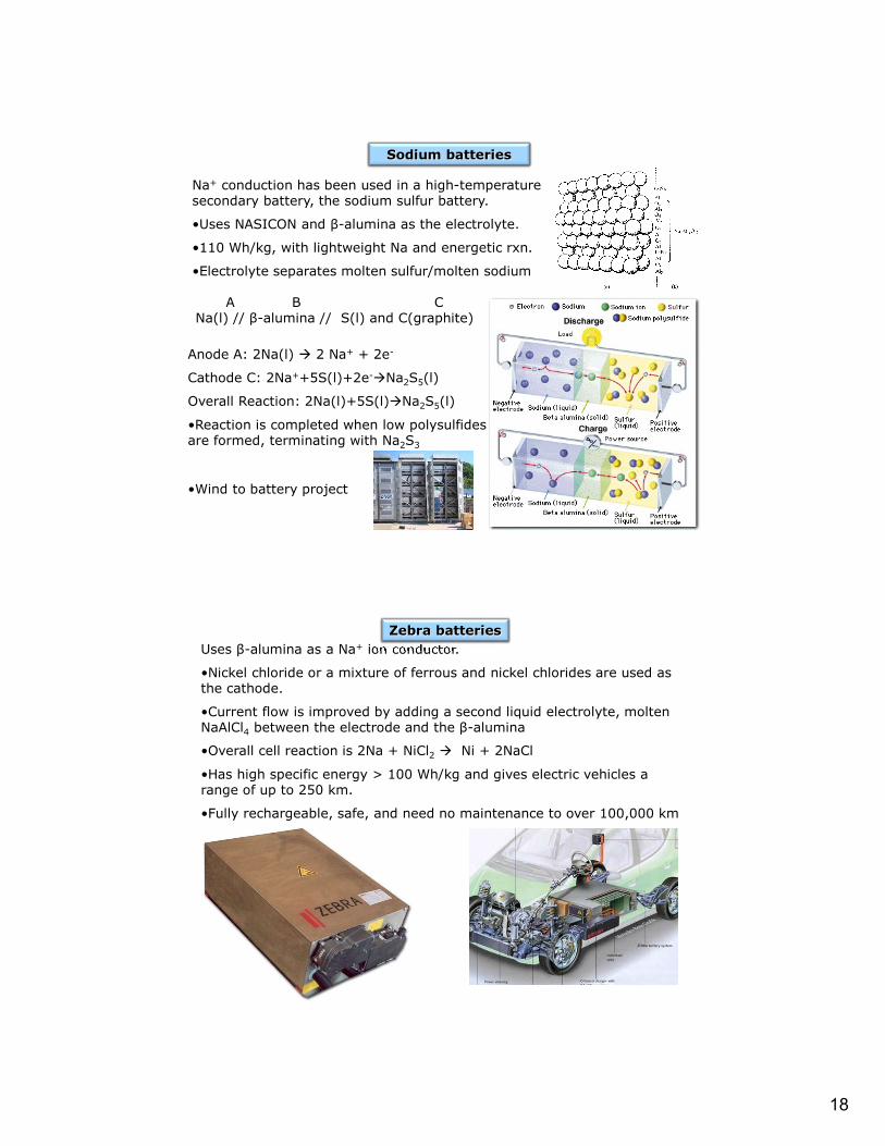
Na+ conduction has been used in a high-temperature secondary battery, the sodium sulfur battery.
•Uses NASICON and β-alumina as the electrolyte.
•110 Wh/kg, with lightweight Na and energetic rxn.
•Electrolyte separates molten sulfur/molten sodium
A B CNa(l) // β-alumina // S(l) and C(graphite)
Anode A: 2Na(l) 2 Na+ + 2e-
Cathode C: 2Na++5S(l)+2e-Na2S5(l)
Overall Reaction: 2Na(l)+5S(l)Na2S5(l)
•Reaction is completed when low polysulfides are formed, terminating with Na2S3
•Wind to battery project
Sodium batteries
Uses β-alumina as a Na+ ion conductor.
•Nickel chloride or a mixture of ferrous and nickel chlorides are used as the cathode.
•Current flow is improved by adding a second liquid electrolyte, molten NaAlCl4 between the electrode and the β-alumina
•Overall cell reaction is 2Na + NiCl2 Ni + 2NaCl
•Has high specific energy > 100 Wh/kg and gives electric vehicles a range of up to 250 km.
•Fully rechargeable, safe, and need no maintenance to over 100,000 km
Zebra batteries

19
Fuel Cells
Fuel cells differ from conventional batteries in that the fuel is fed in externally to the electrodes.
•Advantage: cell can operate continuously as long as fuel is available, unlike a battery that must be discarded (primary) or recharged (secondary).
•The fuels used are usually hydrogen and oxygen (air), which react electrochemically to produce water, electricity and heat.
•H2 is fed to the anode where it is oxidized to H+ ions and electrons.
•Electrons travel through the external circuit and the H+ ions travel through the electrolyte to the cathode, where they react with O2-.
•The reaction process is ‘green’ with byproducts of water and heat.
•The low temperature of the reaction means NOx are avoided.
•Efficiency is up to about 50% or more, compared to 15-20% for ICE and 30% for diesel engines.
•Reduction of oxygen at the cathode is rather slow at low temperatures, therefore a Pt catalyst is incorporated into the carbon electrodes.
Fuel Cells

20
A B CH2(g)//Pt/C electrode// hydrogen electrolyte //Pt/C electrode//O2(g)
•Electrode reactions are:
Anode A: H2(g) 2H+ + 2e-
Cathode C: 1/2O2(g) + 2H+ +2e- H2O
•The theoretical emf is E0 = 1.229 V at 298K, but decreases to ~1 V at 500 K, so a compromise is needed between voltage and operating temperature.
•Hydrogen storage is difficult, as well as the transportation (heavy cylinders for transportation), and changeover of the current infrastructure.
•Production of very pure hydrogen is energy intensive, thus cheap sources of electricity must be found (solar, hydroelectric, nuclear) or through the use of reforming reactions from methane or methanol with steam to produce hydrogen and CO2.
Fuel Cells
Phosphoric Acid Fuel Cell (PAFC)
H2 → 2 H+ + 2e- ½ O2 + 2 H+ + 2e- → H2O
21
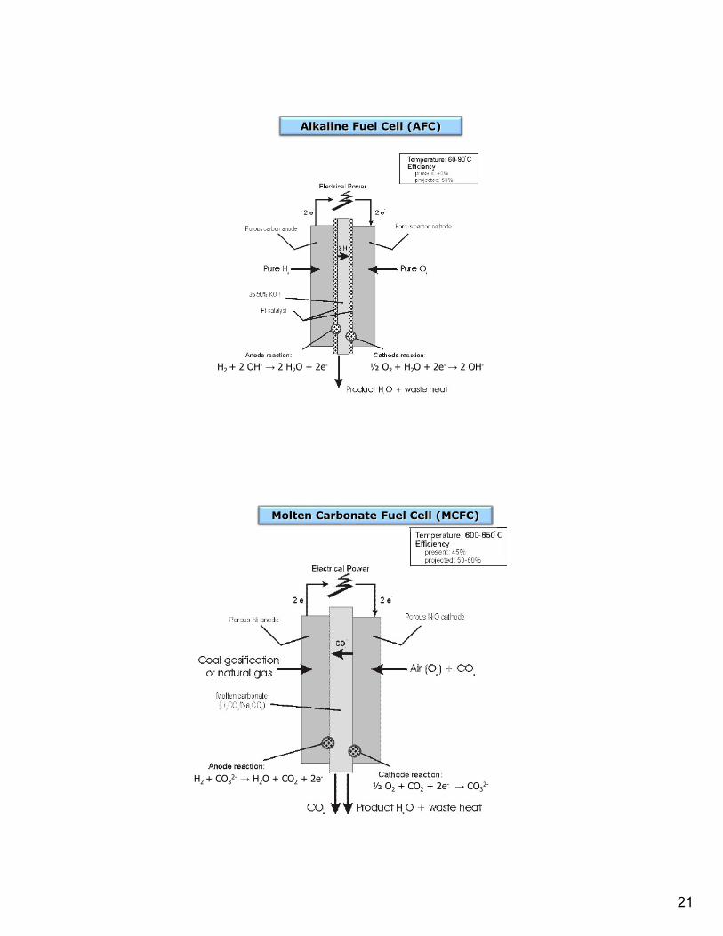
Alkaline Fuel Cell (AFC)
H2 + 2 OH- → 2 H2O + 2e- ½ O2 + H2O + 2e- → 2 OH-
Molten Carbonate Fuel Cell (MCFC)
H2 + CO32- → H2O + CO2 + 2e-
½ O2 + CO2 + 2e- → CO32-
22
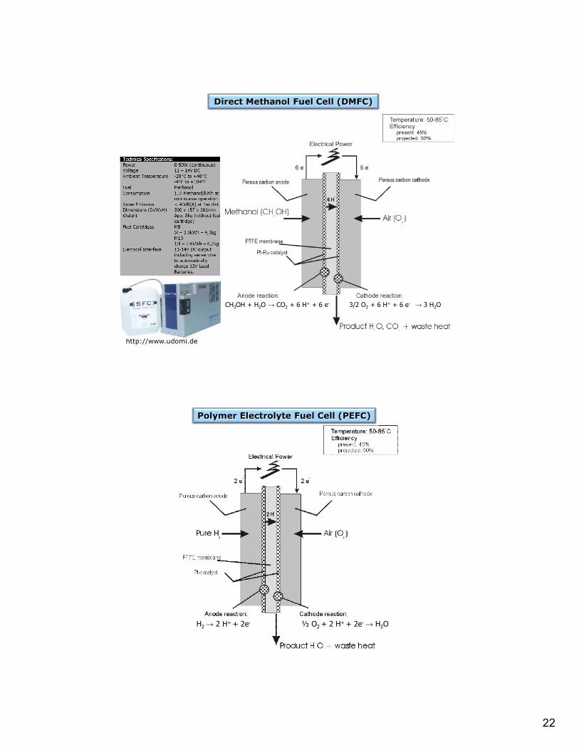
http://www.udomi.de
Direct Methanol Fuel Cell (DMFC)
CH3OH + H2O → CO2 + 6 H+ + 6 e- 3/2 O2 + 6 H+ + 6 e- → 3 H2O
Polymer Electrolyte Fuel Cell (PEFC)
H2 → 2 H+ + 2e- ½ O2 + 2 H+ + 2e- → H2O
23
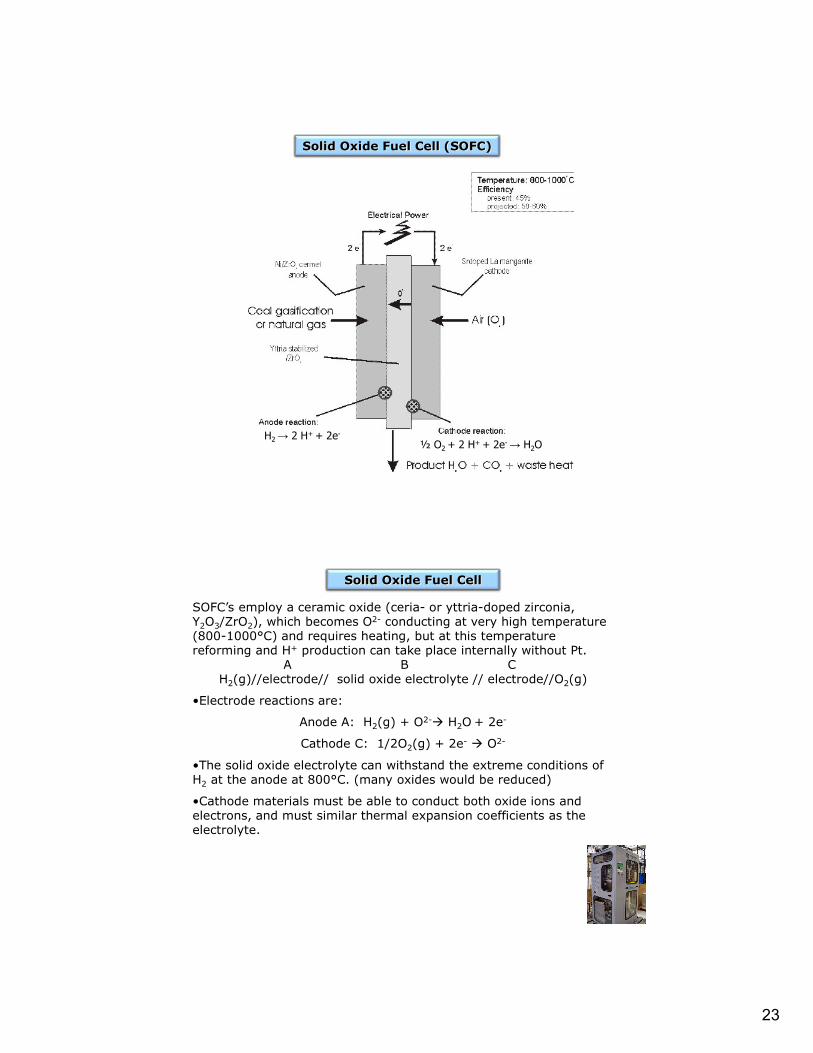
Solid Oxide Fuel Cell (SOFC)
H2 → 2 H+ + 2e-
½ O2 + 2 H+ + 2e- → H2O
SOFC’s employ a ceramic oxide (ceria- or yttria-doped zirconia, Y2O3/ZrO2), which becomes O2- conducting at very high temperature (800-1000°C) and requires heating, but at this temperature reforming and H+ production can take place internally without Pt.
A B CH2(g)//electrode// solid oxide electrolyte // electrode//O2(g)
•Electrode reactions are:
Anode A: H2(g) + O2- H2O + 2e-
Cathode C: 1/2O2(g) + 2e- O2-
•The solid oxide electrolyte can withstand the extreme conditions of H2 at the anode at 800°C. (many oxides would be reduced)
•Cathode materials must be able to conduct both oxide ions and electrons, and must similar thermal expansion coefficients as the electrolyte.
Solid Oxide Fuel Cell
24
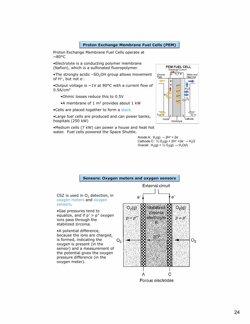
Proton Exchange Membrane Fuel Cells operate at ~80°C
•Electrolyte is a conducting polymer membrane (Nafion), which is a sulfonated fluoropolymer.
•The strongly acidic –SO2OH group allows movement of H+, but not e-.
•Output voltage is ~1V at 80°C with a current flow of 0.5A/cm2
•Ohmic losses reduce this to 0.5V
•A membrane of 1 m2 provides about 1 kW
•Cells are placed together to form a stack
•Large fuel cells are produced and can power banks, hospitals (250 kW)
•Medium cells (7 kW) can power a house and heat hot water. Fuel cells powered the Space Shuttle.
Proton Exchange Membrane Fuel Cells (PEM)
Anode A: H2(g) → 2H+ + 2e-
Cathode C: ½ O2(g) + 2H+ +2e- → H2OOverall: H2(g) + ½ O2(g) → H2O(l)
CSZ is used in O2 detection, in oxygen meters and oxygen sensors.
•Gas pressures tend to equalize, and if p’ > p” oxygen ions pass through the stabilized zirconia.
•A potential difference, because the ions are charged, is formed, indicating the oxygen is present (in the sensor) and a measurement of the potential gives the oxygen pressure difference (in the oxygen meter).
Sensors: Oxygen meters and oxygen sensors
25
Oxygen gas is reduced to O2- at the right-hand electrode (C). The oxide ions are able to pass through the doped zirconia and are oxidized to oxygen gas at the left-hand electrode (A).
•Electrode reactions are:
Anode A: 2O2- O2(p”) + 4e-
Cathode C: O2(p’) + 4e- 2O2-
Overall: O2(p’) O2(p”)
Under standard conditions, the change in Gibb’s Free energy is related to the standard emf of the cell:
DGo = -nEoF
Nernst equation - allows calculation of the cell emf under nonstandard conditions, E. Assume the cell reaction is given by a general equation: aA = bB +… + ne xX yY +…
bB
aA
yY
xXo
aa
aa
nF
RTEE log
303.2
where the quantities ax are the activities of the reactants and products.
Sensors: Oxygen meters and oxygen sensors
Applying the Nernst equation to the cell reaction in an oxygen meter:
Eo is zero, since under standard conditions the oxygen pressure is equal.
•Typically the pressure of the oxygen on one side of the cell (p”) is set to be a known reference pressure, usually either pure oxygen at 1 atm or atmospheric oxygen pressure (~0.21 atm).
•All of the quantities in the equation are known or can be measured, enabling a direct measure of the unknown oxygen pressure p’.
'
"log
4
303.2
p
p
F
RTEE o
ref
o
p
p
F
RTEE
'log
4
303.2
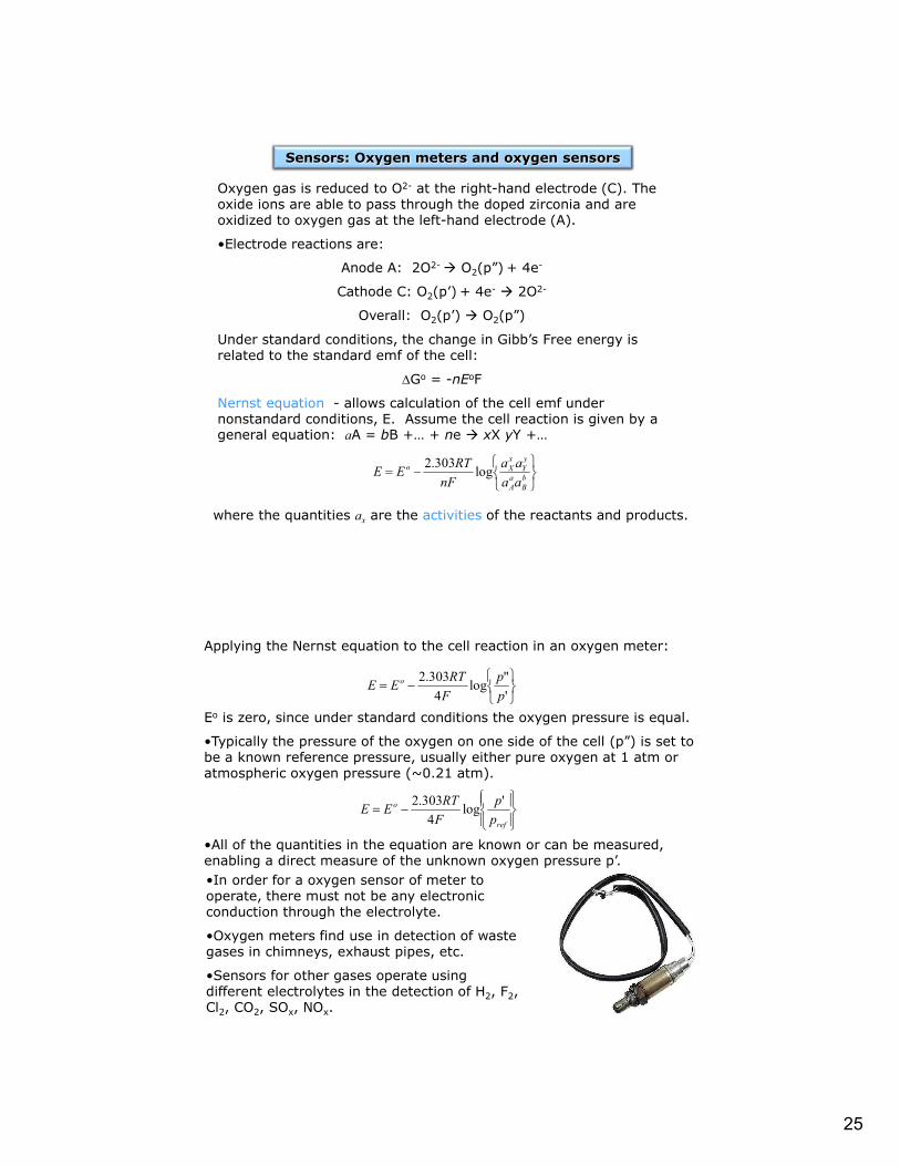
•In order for a oxygen sensor of meter to operate, there must not be any electronic conduction through the electrolyte.
•Oxygen meters find use in detection of waste gases in chimneys, exhaust pipes, etc.
•Sensors for other gases operate using different electrolytes in the detection of H2, F2, Cl2, CO2, SOx, NOx.

26
•Electric current is applied to the cell, causing a movement of ions through the electrolyte and creating a colored compound in one of the electrodes.
•Li+ ions flow from the anode, through the colorless electrolyte to form LixWO3 at the cathode, changing it from colorless to deep blue.
Granqvist et al Appl. Phys. A 89, 29–35 (2007)
Electrochromic Devices
http://eetd.lbl.gov/l2m2/tms-mirrors.html
•The film used for the switchable mirror is made of an alloy of magnesium and one or more transition-metals.
Thin Ni-Mg films, on exposure to hydrogen gas or on reduction in alkaline electrolyte, the films become transparent. The transition is believed to result from formation of nickel magnesium hydride, Mg2NiH4.
Transition-Metal Switchable Mirrors
27
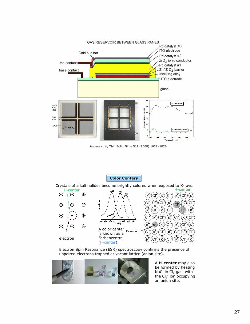
Anders et al, Thin Solid Films 517 (2008) 1021–1026
Crystals of alkali halides become brightly colored when exposed to X-rays.
electron
A color center is known as a Farbenzentre(F-center).
Electron Spin Resonance (ESR) spectroscopy confirms the presence of unpaired electrons trapped at vacant lattice (anion site).
A H-center may also be formed by heating NaCl in Cl2 gas, with the Cl2- ion occupying an anion site.
Color Centers
F-center H-center

28
Impurity induced defects are extrinsic and maintain charge neutrality.
Color centers in NaCl may be formed heat heating in the presence of Na vapor, becoming Na1+xCl, where the sodium atom occupies cation sites, creating anion vacancies. The sodium atoms oxidize to form a sodium cation with an electron at the anion vacancy.
•The resulting compound is known as a non-stoichiometric compound because the number of atomic components is no longer 1:1.
•Ionic compounds may also be non-stoichiometric when it contains an element with a variable valency, then a change in the number of ions of that element can be compensated with changes in ion charge.
Compound Composition range
TiOx [≈TiO] 0.65 < x <1.25
[≈TiO2] 1.998 < x < 2.000
VOx [≈VO] 0.79 < x < 1.29
MnxO [≈MnO] 0.848 < x <1.000
FexO [≈FeO] 0.833 < x <0.957
CoxO [≈CoO] 0.998 < x < 1.000
NixO [≈NiO] 0.999 < x <1.000
CeOx [≈Ce2O3] 1.50 < x < 1.52
ZrOx [≈ZrO2] 1.700 < x < 2.004
UOx [≈UO2] 1.65 < x < 2.25
LixWO3 0< x < 0.50
•Isolated point defects are not randomly located in non-stoichiometric compounds, but are dispersed in a regular pattern.
•Conventional XRD gives average structure, local structure may be investigated using high resolution electron microscopy (HREM) and direct lattice imaging.
Non-stoichiometric Compounds
Ferrous oxide, or wustite (FeO) has the NaCl structure type.
• Chemical analysis indicates it is non-stoichiometric and always deficient in iron. Stoichiometric FeO isn’t stable, and below 570°C disproportionates into α-Fe and Fe3O4.
• Iron deficiency may be accommodated in the structure on one of two ways:
1. Iron vacancies, giving Fe1-xO
2. Excess of oxygen in interstitial positions, giving FeO1+y
Non-stoichiometry in Wustite (FeO)

29
It is often found that non-stoichiometric compounds have a unit cell size that varies smoothly with composition but has symmetry that is unchanged, which is known as Vegard’s Law.
O:Fe ratio
Fe:O ratio
Lattice parameter /pm
Observed density (g/cm3)
Interstitial O (g/cm3)
Fe Vacancies (g/cm3)
1.058 0.945 430.1 5.728 6.075 5.742
1.075 0.930 429.2 5.658 6.136 5.706
1.087 0.920 428.5 5.624 6.181 5.687
1.099 0.910 428.2 5.613 6.210 5.652
428
428.5
429
429.5
430
430.5
0.905 0.91 0.915 0.92 0.925 0.93 0.935 0.94 0.945 0.95
Fe:O Ratio
La
ttice
Pa
ram
ete
r (p
m)
Vegard’s Law
Compensation for iron deficiency is energetically more favorable to oxidize Fe(II), requiring the oxidation of two Fe2+ to Fe3+ for every Fe2+
cation vacancy.
•In the case of excess metal, neighboring cations would be reduced.•In the case of an Fe2+ vacancy, the two Fe3+ vacancies are determined to be neighboring as confirmed by Mossbauer spectroscopy.•Some Fe3+ ions are found to be in a tetrahedral site.•If the tetrahedral site is occupied, then the thirteen neighboring octahedral Fe2+ sites are empty.•This type of defect is found for low values of x.•At high values of x, the structure contains various types of defect clusters, one possibility is a Koch-Cohen cluster.
Electronic Defects and Structure in FeO

30
•A defect cluster is a region of the crystal where defects form an ordered structure.
•Surrounding the central defect unit cell, the other octahedral iron sites (Feoct) are occupied, but may contain either Fe2+ or Fe3+.
•Clusters sometimes referred to the ratio of cation vacancies to interstitial Fe3+ in tetrahedral holes (13:4).
Koch-Cohen Cluster
*Front and back plans cut away for clarity
•Above 1127°C, a single oxygen-rich non-stoichiometric phase of UO2 is found with formula UO2 to UO2.25 (U4O9)
•Interstitial anions are present in the fluorite structure.
•Interstitial O’ causes O’’ displacement.
•A defect cluster, considered as two vacancies, one interstitial of one kind O’, and two of another O’’, is called a 2:1:2 Willis cluster.
•The movement of the interstitial oxide O’ is along the direction towards the diagonal of the cube face (110) direction, whereas the O’’ is along cube diagonal (111)
•Can consider UO2 as containing microdomains of U4O9structure within UO2.
Uranium Dioxide

31
•Composition ranges from TiO0.65 to TiO1.25, with a stoichiometric 1:1 composition resembling the NaCl-type structure with vacancies in both the metal and oxygen sublattices: 1/6 of Ti and 1/6 of O are missing.
•Vacancies are randomly distributed above 900°C, but below are ordered.
•The structure appears stoichiometric, but contains defects on both the cation and anion sublattices.•Note that every other atom along every third diagonal plane is missing.•The new unit cell is monoclinic (β ≠ 90°)•Vacancies permit sufficient contraction of the lattice to enable 3d orbitals on Ti to overlap, broadening the conduction band and allowing electronic conduction.
Titanium Monoxide (TiO)
•TiO1.25 has all of the oxygens present and one in every five Ti missing.
•Ordering produces a superlattice with a different unit cell.
•Formula would be more correctly written as Ti0.8O (Ti1-xO) because this indicates the structure contains interstitial vacancies.
Titanium Monoxide (TiO1.25)
32
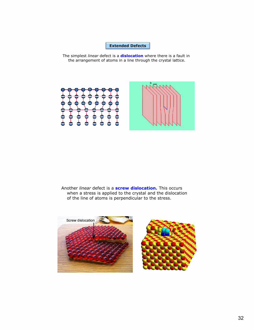
The simplest linear defect is a dislocation where there is a fault in the arrangement of atoms in a line through the crystal lattice.
Extended Defects
Another linear defect is a screw dislocation. This occurs when a stress is applied to the crystal and the dislocation of the line of atoms is perpendicular to the stress.

33
Antiphase domain: the grain has the reverse structure from the surrounding structure.
There are also planar defects such as grain boundaries.
Chemical twinning(planar defects) contains unit cells mirrored about the twin plane through the crystal.

34
Non-stoichiometric compounds are found for the higher oxides of tungsten (WO3-x), molybdenum (MoO3-x), and titanium (TiO2-x).
•In these systems a series of closely related compounds with similar formula exist (MonO3n-1, WnO3n-1 and WnO3n-2, and TinO2n-1, where n can take values of 4 and above). The resulting series of oxides is known as a homologous series.
•These compounds have regions of corner-sharing octahedra separated from each other by regions of a different structure known as a crystallographic shear plane.
•The different members of a homologous series are determined by the fixed spacing between the crystallographic shear planes.
•Above 900°C, the WO3 structure is that of ReO3, which has [WO6] octahedra sharing corners with any octahedron lined to four others in the same layer.
•Non-stoichiometry is WO3-x is achieved by some of the octahedra in this structure changing from corner-sharing to edge-sharing.
•Shearing occurs at regular intervals and creates groups of four octahedra which share edges.
•Direction of maximum density of edge sharing groups in the CS plane.
Crystallographic Shear Planes
WO3 WO3-x
WOO
OO=

35
Formation of Shear Structure= W
OO
OO
The four octahedra consist of four W atoms and 18 O atoms.
•14 of the O are linked to other octahedra and 4 O are involved in edge sharing within the group.
•The overall stoichiometry is given by 4W + (14*1/2)O+4O = W4O11
•If groups of W4O11 are interspersed throughout the WO3structure, the groups can be written as WO3-x.
•W4O11 + WO3 = W5O14
•W4O11 + 2WO3 = W6O17
•W4O11 + 3WO3 = W7O20
•W4O11 + 4WO3 = W8O23
•Simplifies to WnO3n-1

36
Shear Structure: W4O11 + 7WO3 W11O32
The term bronze is applied to metallic oxides that have a deep color (yellow to red or deep purple), metallic luster, and are metallic or semiconducting.
•Color depends on x in NaxWO3.
•Structure is a 3d network of channels throughout the structure, with alkali metals in the channels.
•Three main types of structures:
1. Cubic, 2. Tetragonal, 3. Hexagonal
•Charge compensation occurs with the M+ presence, reducing the metal M5+.
•In the case of K, stability lies in the range of K0.19WO3 to K0.33WO3, below 0.19 the structure has WO3 intergrownwith the hexagonal structure in a regular fashion.
•Layers of hexagonal structure 1 or 2 tunnels wide. Hexagonal
Tetragonal
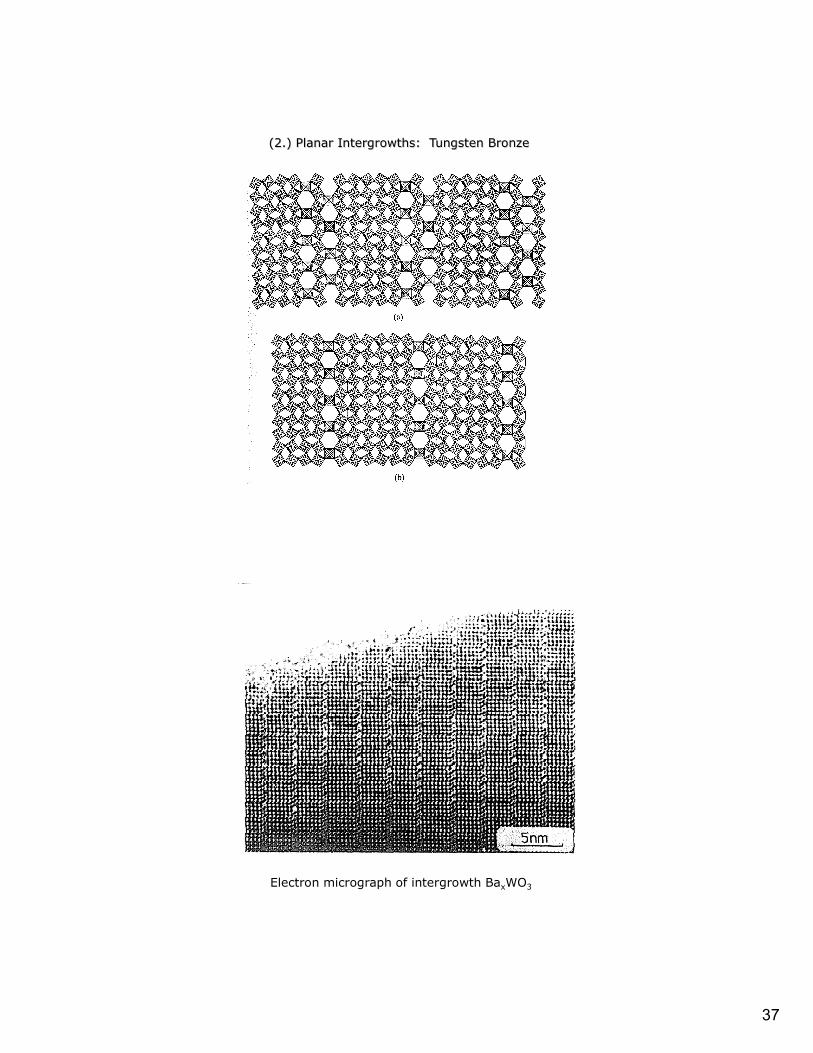
(2.) Planar Intergrowths: Tungsten Bronze
37
(2.) Planar Intergrowths: Tungsten Bronze
Electron micrograph of intergrowth BaxWO3

38
High-resolution electron micrograph of W4Nb26O77
In O-deficient Nb2O5, and mixed oxides of Nb and Ti, and Nb and W, the crystallographic shear planes occur in two sets at right angles to each other.
•Intervening regions of perfect structure change from infinite sheets to infinite columns or blocks, which are known as double shear or block structures.
•Characterized by the cross sectional size of the blocks.
•May also have blocks of two or three different sizes arranged in an ordered fashion, such as the 4x4 and 3x4 blocks in W4Nb26O77.
Three-Dimensional Defects: Block Structures
•Structure consists of a pentagonal ring of five [MO6] octahedra, which when stacked form a pentagonal column with alternating M and O atoms.
•The pentagonal columns fit inside an ReO3 type structure in an ordered way and, depending on the spacing, form a homologous series.
•One example is the Mo5O14structure.
Mo5O14
Three-Dimensional Defects: Pentagonal Columns

39
Ta22W4O67
Ta30W2O81
•A large number of compounds form in the Ta2O5-WO3 system, built from fitting together pentagonal columns.
•Structure have a wavelikeskeleton of pentagonal columns.
•As the composition varies, the ‘wavelength’ of the backbone changes, giving rise to a huge number of possible ordered structures, know as infinitely adaptive structures.
Three-Dimensional Defects: Infinitely Adaptive Structures
Four basic types of compounds are non-stoichiometric:Metal excess (reduced metal)Type A: anion vacancies present formula MO1-x (e.g. TiO, VO, ZrS)Type B: interstitial cations formula M1+xO (e.g. CdO, ZnO)Metal deficiency (oxidized metal)Type C: interstitial anions formula MO1+x
Type D: cation vacancies M1-xO (e.g. TiO, VO, MnO, FeO, CoO)
Electronic Properties of Non-stoichiometric Oxides

40
Type A oxides: Compensate for metal excess with anion vacancies. Two electrons have to be introduced for each anion vacancy, which may be trapped at the vacant anion site. More likely to find electrons associated with the reduction of nearby metal cations from M2+ to M+.
Type B oxides: Have a metal excess incorporated into the lattice in interstitial positions. Most likely that an interstitial atom is ionized, reducing nearby metal cations from M2+ to M+.
Type C oxides: Compensate for the lack of metal with interstitial anions. Charge balance is maintained by creation of two M3+
cations for each interstitial anion (O2-).
Conductivity:
(i) depends on d-orbital overlap – the bigger the overlap the greater the band widthand electrons in the band are delocalized over the whole structure.
(ii) interelectronic repulsion tends to keep electrons localized on individual atoms.

41
TiO and VO are metallic conductors – have good overlap between d-orbitals (forming a d-electron band), partly because Ti and V are early in the transition series and the d orbitals have not suffered contraction due to increase nuclear charge as is later in the series.
-TiO also has 1/6 of the Ti and O missing from NaCl structure type, leading to a contraction of the structure and better d overlap.
MnO, FeO, CoO, and NiO are insulators - the d-orbitals are too contracted to overlap much, with typical band width 1 eV, and the overlap is not sufficient to overcome the localizing influence of interelectronic repulsions. Gives rise to magnetic properties.
Non-stoichiometric oxides, types A and B metal excess monoxides, have extra electrons to compensate for excess metal in the structure. These electrons can be free to move through the lattice and are not necessarily bound to a particular atom.
-thermal energy is enough to make the electrons move and conductivity increases with temperature (like a semiconductor).
Compounds of type A and B would produce n-type semiconductors because the conduction is produced by electrons.
•Consider the conduction electrons (or holes) as localized, or trapped, at atoms or defects instead of delocalized in bands.
•Conduction occurs by jumping or hopping from one site to another under the influence of an electric field.
•Energetically, electron ‘jumps’ between two valence states (e.g. Zn+ and Zn2+), it doesn’t take much energy.
•These are called hopping semiconductors and can be described in the same way as ionic conduction.
•The mobility (m) for a charge carrier (electron or positive hole), is an activated process.
m is proportional to e(-Ea/kT)
where Ea is the activation energy of the hop (0.1 to 0.5 eV).
The hopping conductivity is = nem
where n is the number of mobile charge carriers per unit volume and e is the electronic charge. n doesn’t depend on temperature, only on composition.

42
Compounds of type C and D monoxides have M3+ ions, which can be regarded as a positive hole compared to the M2+ cation.
•if sufficient energy is available, conduction can be thought to occur via the positive hole hopping to another M2+ cation, giving rise to p-type electronic conductivity.
•This type of conductivity is found for MnO, CoO, NiO, and FeO
Non-stoichiometric oxides cover the entire range from metal to insulator.
•Others, such as TiO2 and WO3 require a different description.
•Each structure needs to be examined individually in terms of conductivity.
Doping compounds with an impurity extends the range of properties:
0.5x Li2O + (1-x)NiO + 1/4x O2 LixNi1-xO
where Ni2+ is oxidized to Ni3+, creating a high concentration of positive holes located at Ni cations. This process is known as valence induction.
In greatly increase the conductivity range of NiO – at high Li concentration the conductivity approaches that of a metal.


![Conheça PIGEONS OUT site · î î l ì î l î ì í ô ð D ] ] } ] u î î l ì î l î ì í ô ñ î Ñ } W ( ] Æ } } ] } K } } } u } u ( ] Æ } } ] } } u ( µ } X](https://static.fdocuments.us/doc/165x107/60cb083c8c9e68599a6f6bad/conhefa-pigeons-out-site-l-l-d-u-l-.jpg)

![$= X &DSWDLQ E ^&^ / v À ] ] } v o µ P î î v t î ï · K o ] À ] D Ì Ì v } · î ï ^^ U î î ì î î ] v } ] · ò î U ^^ î ì î î : } v D D Z } v · ñ K µ ( ] o](https://static.fdocuments.us/doc/165x107/5fd89c25f3a0516e76322c26/-x-dswdlq-e-v-v-o-p-v-t-k-o-d-oe.jpg)


![v v o µ ] W o v î ì î ì r î í l î ì î î r î ... · / v v o µ ] W o v î ì î ì r î í l î ì î î r î ï ( / v v o µ ] W o v î ì î ì r î í l î ì î î](https://static.fdocuments.us/doc/165x107/600570084499ff768d735382/v-v-o-w-o-v-r-l-r-v-v-o-w-o-v-.jpg)
![ΠΠΠΠΠΠΠΠΠΠΠΠΠΤΠΠΠCOMPANY PROFILE 2 engKDW Ez [^ WZK&/> , >> E/ h /d/E' ^ X X, ] } Ç d Z } u v Ç Á ( } µ v ] v: µ v î ì í ì v ] ( r P } Á](https://static.fdocuments.us/doc/165x107/5fe010b76605db55a425a508/-company-profile-2-eng-kdw-ez.jpg)


