Chapter 5 DATA COLLECTION - Oklahoma
44
ODOT ROADWAY DRAINAGE MANUAL November 2014 Chapter 5 DATA COLLECTION
Transcript of Chapter 5 DATA COLLECTION - Oklahoma

ODOT ROADWAY DRAINAGE MANUAL
November 2014
Chapter 5
DATA COLLECTION


ODOT Roadway Drainage Manual November 2014
Data Collection 5-i
Chapter 5 DATA COLLECTION
Table of Contents
Section Page
5.1 INTRODUCTION ..................................................................................................... 5.1-1
5.1.1 Overview ................................................................................................ 5.1-1 5.1.2 Data Retention Policy ............................................................................ 5.1-1
5.2 TYPES OF DATA NEEDED .................................................................................... 5.2-1
5.2.1 General .................................................................................................. 5.2-1 5.2.2 Watershed Characteristics .................................................................... 5.2-1
5.2.2.1 Contributing Size ............................................................... 5.2-1 5.2.2.2 Slopes ............................................................................. 5.2-2 5.2.2.3 Watershed Land Use ........................................................ 5.2-2 5.2.2.4 Streams, Rivers, Ponds, Lakes, Wetlands and
Detention Basins ............................................................... 5.2-3
5.2.3 Environmental Considerations ............................................................... 5.2-3 5.2.3.1 Environmental Sensitivity .................................................. 5.2-3 5.2.3.2 Water Quality Data ............................................................ 5.2-4 5.2.3.3 Mitigation ........................................................................... 5.2-4 5.2.3.4 Wetlands ........................................................................... 5.2-4
5.2.4 Site Characteristics ................................................................................ 5.2-4
5.2.4.1 Geomorphological Data .................................................... 5.2-5 5.2.4.2 Roughness Coefficients .................................................... 5.2-5 5.2.4.3 Stream Profile ................................................................... 5.2-5 5.2.4.4 Stream Cross Sections ..................................................... 5.2-5 5.2.4.5 Existing Structures ............................................................ 5.2-5 5.2.4.6 Acceptable Flood Levels ................................................... 5.2-6 5.2.4.7 Flood History ..................................................................... 5.2-6 5.2.4.8 Debris and Ice ................................................................... 5.2-6 5.2.4.9 Scour Potential .................................................................. 5.2-6
5.2.5 Controls Affecting Design Criteria ......................................................... 5.2-7
5.2.5.1 Downstream Control ......................................................... 5.2-7 5.2.5.2 Upstream Control .............................................................. 5.2-7
5.3 SOURCES OF DATA .............................................................................................. 5.3-1

ODOT Roadway Drainage Manual November 2014
5-ii Data Collection
Table of Contents (Continued)
Section Page 5.3.1 Geographic Information Systems (GIS) ................................................. 5.3-1 5.3.2 National Flood Insurance Program ........................................................ 5.3-1 5.3.3 Sources ................................................................................................. 5.3-1
5.4 DATA COLLECTION PROCESSES ....................................................................... 5.4-1
5.4.1 Overview ................................................................................................ 5.4-1 5.4.2 Field Data Collection ............................................................................. 5.4-1 5.4.3 Digital and Satellite Data Models ........................................................... 5.4-1 5.4.4 Aerial Photogrammetry and Surveys ..................................................... 5.4-2 5.4.5 Data Merging ......................................................................................... 5.4-2 5.4.6 Accuracy of Data ................................................................................... 5.4-3
5.5 FIELD REVIEWS .................................................................................................... 5.5-1
5.5.1 General .................................................................................................. 5.5-1 5.5.2 Preparation of Preliminary Drainage Data ............................................. 5.5-1
5.5.2.1 Transfer Road Alignment to Quadrangle Map .................. 5.5-1 5.5.2.2 Determine Drainage Areas ............................................... 5.5-2 5.5.2.3 Determine Channel Slopes ............................................... 5.5-3
5.5.3 Conducting the On-Site Inspection ........................................................ 5.5-3
5.6 DRAINAGE SURVEY INFORMATION .................................................................... 5.6-1
5.6.1 General .................................................................................................. 5.6-1 5.6.2 Survey Locations ................................................................................... 5.6-1 5.6.3 Drainage Survey Needs ........................................................................ 5.6-2
5.7 DATA EVALUATION ............................................................................................... 5.7-1
5.7.1 Objective ................................................................................................ 5.7-1 5.7.2 Reliability ............................................................................................... 5.7-1 5.7.3 Sensitivity .............................................................................................. 5.7-1
5.8 REFERENCES ........................................................................................................ 5.8-1 APPENDIX A DATA SOURCES ......................................................................................... 5.A-1
A.1 PRINCIPLE WATERSHED DATA SOURCES ...................................... 5.A 1 A.2 PRINCIPLE WATERSHED DATA SOURCES ...................................... 5.A 1 A.3 PRINCIPLE SITE DATA SOURCES ..................................................... 5.A 2 A.4 PRINCIPLE REGULATORY DATA SOURCES .................................... 5.A 2 A.5 PRINCIPLE ENVIRONMENTAL DATA SOURCES .............................. 5.A 3

ODOT Roadway Drainage Manual November 2014
Data Collection 5-iii
Table of Contents (Continued)
Section Page A.6 PRINCIPLE DEMOGRAPHIC, ECONOMIC AND POLITICAL
DATA SOURCES .................................................................................. 5.A 3 A.7 OTHER DATA SOURCES ..................................................................... 5.A 4
APPENDIX B FIELD INVESTIGATION FORMS..................................................................5.B 1

ODOT Roadway Drainage Manual November 2014
5-iv Data Collection
List of Figures
Section Page
Figure 5.B-A — ODOT FIELD INVESTIGATION FORM .................................................... 5.B-2
Figure 5.B-B — ODOT HYDRAULIC SURVEY FIELD INVESTIGATION CHECKLIST ..... 5.B-4

ODOT Roadway Drainage Manual November 2014
Data Collection 5.1-1
Chapter 5 DATA COLLECTION
5.1 INTRODUCTION
The hydraulics designer should identify the types of data that will be required prior to conducting the hydraulic analysis. The effort necessary for data collection and compilation should be tailored to the importance of the project. Not all data discussed in this chapter will be needed for every project.
Data collection for a specific project should be appropriate for the project scope and be tailored to:
• site conditions; • scope of the hydraulic analysis; • social, economic, environmental and archaeological requirements; • unique project requirements; and • regulatory requirements. Uniform or standardized survey requirements for all projects may prove uneconomical or data deficient for a specific project. Special instructions outlining data requirements may have to be provided to the survey party by the hydraulics designer for unique sites.
Coordination with the appropriate local, state and Federal agencies to identify any regulatory/permitting requirements before the initial field work has begun, will help ensure the acquisition of sufficient but not excessive data collection. This early coordination could also save an additional trip to the site.
5.1.1 Overview
This Chapter outlines the types of data that are normally required for drainage analysis and design, possible sources and other aspects of data collection. The following subjects are presented:
• types of data (Section 5.2), • sources of data (Section 5.3), • data collection processes (Section 5.4), • field reviews (Section 5.5), • drainage survey information (Section 5.6), and • data evaluation reliability (Section 5.7). 5.1.2 Data Retention Policy
The hydraulic project file and all of its contents should be readily available for use during construction, for defense of litigation and for future improvements. Hydrologic/hydraulics

ODOT Roadway Drainage Manual November 2014
5.1-2 Data Collection
documentation should be retained permanently, even after the drainage facility is totally replaced or modified as a result of a new drainage study.
A scanned electronic copy of the hydraulic project file can be the permanent record. Hardcopies should be kept for five years or can be destroyed three years after construction has been completed.

ODOT Roadway Drainage Manual November 2014
Data Collection 5.2-1
5.2 TYPES OF DATA NEEDED
5.2.1 General
The hydraulics designer should compile the data that are specific to the subject site. Following are the major types of data that may be required:
• permit requirements;
• watershed characteristics;
• stream-reach data;
• other physical data within the vicinity of the facility (e.g., utilities, easements);
• hydrologic and meteorologic data (e.g., stream-flow and rainfall data related to maximum or historical peak and low-flow discharges and hydrographs applicable to the site);
• existing and proposed land-use data in the subject drainage area and in the general vicinity of the facility;
• anticipated changes in land-use and/or watershed characteristics; and
• floodplain limits, environmental regulations and archaeological data.
Watershed, stream-reach and site characteristic data and data on other physical characteristics can be obtained from a field reconnaissance of the site. Examination of available maps and aerial photographs of the watershed are also excellent methods of defining physical characteristics of the watershed.
5.2.2 Watershed Characteristics
Following is a brief description of the major data topics that relate to drainage facility analysis and design. Additional information is discussed in Chapter 2 “Hydrology” of the AASHTO Highway Drainage Guidelines (1) and FHWA HDS-2 (2).
5.2.2.1 Contributing Size
The size of the contributing drainage area expressed in acres or square miles is determined from some or all of the following:
• digital elevation modeling software (e.g., WMS, StreamStats, mapping software);
• U.S. Geological Survey (USGS) topographic maps are available for most areas of the state. Topographic maps can also be obtained from most municipal and county governments and local developers;
• aerial maps or photographs are available for many counties in the state; check:

ODOT Roadway Drainage Manual November 2014
5.2-2 Data Collection
○ ODOT Survey Division, and ○ U.S. Department of Agriculture (USDA) Aerial Photography Field Office.
• direct field surveys with conventional surveying instruments;
• field checks to determine any changes in the contributing drainage area such as:
○ urbanization, ○ terraces, ○ lakes and sinks, ○ debris or mud flow barriers, ○ reclamation/flood-control structures, ○ irrigation diversions, ○ storm sewer systems, and ○ landowner alterations.
When determining the size of the drainage basin, document any subterranean flow loss zones (e.g., Karst formations) where flow is diverted from the surface waters. Karst is defined as “an irregular limestone region with sinks, underground streams and caverns.” Also define any areas outside the physical boundaries of the drainage area that have runoff diverted into the drainage area being analyzed or any flood waters that are diverted out of the basin before reaching the site.
5.2.2.2 Slopes
Hydrologic and hydraulics procedures presented in this Manual are dependent on watershed slopes and other factors. Determine the stream slope in the vicinity of proposed structures that will be used for the hydraulics analysis and the average slope of the watershed that will be used for the hydrologic analysis.
5.2.2.3 Watershed Land Use
Define and document the existing and expected future land use, particularly the location, degree of anticipated urbanization and data source. This information may be obtained from:
• field reviews, • aerial photographs (conventional and infrared), • zoning maps and master plans, • USGS and other maps, • municipal planning agencies, • landsat (satellite) images, and • Geographic Information Systems (GIS) data. Specific information regarding particular tracts of land can often be obtained from owners, developers, realtors and local residents. Care should be exercised in using data from these sources because their reliability may be questionable, and these sources may not be aware of future development within the watershed that might affect specific land uses.

ODOT Roadway Drainage Manual November 2014
Data Collection 5.2-3
Existing land-use data for small watersheds can best be determined during data collection (see Section 5.4) or verified from a field review (see Section 5.5). Field reviews should also be used to update information on maps and aerial photographs, especially in basins that have experienced changes in development since the maps or photos were prepared. Infrared aerial photographs may be particularly useful in identifying types of urbanization at a point in time.
5.2.2.4 Streams, Rivers, Ponds, Lakes, Wetlands and Detention Basins
The hydraulics designer should secure the following data at all streams, rivers, ponds, lakes and wetlands that will affect or may be affected by the proposed structure or construction. These data are essential in determining the expected hydrology and may be needed for regulatory permits:
• Determine the elevation of normal and high water for various frequencies.
• Prepare a detailed description of any natural or constructed spillway or outlet works including dimensions, elevations and operational characteristics, including emergency spillway works.
• Determine the classification of the water body.
• Document descriptions of adjustable gates, soil and water-control devices.
• Prepare a profile along the top of any dam and a typical cross section of the dam.
• Determine the use of the water resource (e.g., stock water, fish, recreational, power, irrigation, municipal or industrial water supply).
• Note the existing conditions of the stream, river, pond, lake or wetlands as to turbidity and silt.
• Determine riparian ownership(s) as well as water rights.
5.2.3 Environmental Considerations
The need for environmental data in the hydraulic analysis and design stems from the need to investigate and mitigate possible impacts due to specific design configurations. The hydraulics designer should coordinate with the ODOT Environmental Programs Division data needs that are briefly described in the following sections.
5.2.3.1 Environmental Sensitivity
Identify the information necessary to define the environmental sensitivity of the facility’s site relative to impacted surface waters (e.g., water use, water quality and standards, aquatic and riparian wildlife biology, wetlands information). Some of this information is available in the water quality standards and criteria published by the ODOT Environmental Programs Division.

ODOT Roadway Drainage Manual November 2014
5.2-4 Data Collection
5.2.3.2 Water Quality Data
Physical, chemical and biological data for many streams are also available from state and Federal water pollution control agencies, USGS, municipalities, water districts and industries that use surface waters as a source of water supply. In unique cases, a data collection program possibly lasting several years and tailored to the site may be required.
Gather the information necessary to determine the most environmentally compatible design (e.g., circulation patterns, sediment transport data). Data on circulation, water velocity, water quality and wetlands are available from the USGS, U.S. Army Corps of Engineers (USACE), ODOT Environmental Programs Division, universities and local agencies and organizations. Information on sediment transport is vital in defining the suitability of a stream for most beneficial uses including fish habitat, recreational and water supply. Data collection for projects in critical water-use areas (e.g., near municipal or industrial water supply intakes) should be accomplished early in project development to ensure proper coordination.
5.2.3.3 Mitigation
Information necessary to define the need for and design of mitigation measures should be obtained (e.g., fish characteristics (type, size, migratory habits), fish habitat (depth, cover, pool-riffle relationship), sediment analysis, water use, water quality standards, TMDLs). Water quality standards and TMDLs can be obtained from ODEQ. Fish and fish habitat information is available from the U.S. Fish and Wild Life Service (USFWS) and the state department of game, fish and parks.
5.2.3.4 Wetlands
Wetlands are unique and data needs can be identified through coordination with the USFWS, the Natural Resources Conservation Service (NRCS) and the ODOT Environmental Programs Division.
5.2.4 Site Characteristics
A complete understanding of the physical nature of the natural channel or stream reach is of prime importance to a good hydraulic design, particularly at the site of interest. Any work being performed, proposed or completed that changes the hydraulic efficiency of a stream reach should be studied to determine its effect on the stream flow. The hydraulics designer should be aware of plans for channel modifications and any other changes that might affect the facility design. The stream may be classified as:
• rural or urban; • improved or unimproved; • narrow or wide; • rapid or sluggish flow; • stable, transitional or unstable;

ODOT Roadway Drainage Manual November 2014
Data Collection 5.2-5
• sinuous, straight, braided, alluvial or incised; and • perennial or intermittent flow. FHWA HEC-20 (3) and FHWA HDS No. 6 (4) present commonly used stream classification systems.
5.2.4.1 Geomorphological Data
Geomorphological data are important in the analysis of channel stability and scour. Types of needed data, if the stream reach needs to be analyzed, include:
• sediment transport and related data; • stability of form over time (e.g., braided and meandering, pool-riffle relationship); • scour history/evidence of scour; and • bed and bank material identification. 5.2.4.2 Roughness Coefficients
Roughness coefficients, ordinarily in the form of Manning’s n values, should be estimated for the entire flood limits of the stream. See Chapter 8 “Channels” for a tabulation of Manning’s n values with descriptions of their applications.
5.2.4.3 Stream Profile
Stream-bed profile data should be obtained and these data should extend sufficiently upstream and downstream to determine the average slope and to encompass any proposed construction or aberrations usually 500 ft upstream to 500 ft downstream. Identification of “headcuts” that could migrate to the site under consideration are particularly important. Profile data on live streams should be obtained from the water surface. Where there is a stream gage relatively close, the discharge, date and hour of the reading should be obtained.
5.2.4.4 Stream Cross Sections
Stream cross section data should be obtained that represent the conditions at the structure site. Stream cross section data should also be obtained at other locations where stage discharge and related calculations will be necessary.
5.2.4.5 Existing Structures
The location, size, description, condition, observed flood stages and channel section relative to existing structures on the stream reach and near the site should be secured to determine their capacity and effect on the stream flow. Any structures, downstream or upstream, that may cause backwater or retard stream flow should be investigated. Also, note the history of how existing structures have been functioning regarding scour, overtopping, debris and ice passage,

ODOT Roadway Drainage Manual November 2014
5.2-6 Data Collection
fish passage, etc. With bridges, these data include span lengths, types of piers and substructure orientation, which usually can be obtained from existing structure plans. The necessary culvert data includes size, inlet and outlet geometry, slope, end treatment, culvert material and flow-line profile. Highway construction plans may be available to obtain required bridge and/or culvert data. The hydraulics designer should verify the documented as-built conditions through field checks. Photographs and high-water profiles or marks of flood events at the structure and past flood scour data can be valuable when assessing the hydraulic performance of the existing facility.
5.2.4.6 Acceptable Flood Levels
Development and property use adjacent to the proposed site, both upstream and downstream, may determine acceptable flood levels. Note the ground elevations of buildings in the vicinity of structures. In the absence of upstream development, acceptable flood levels may be based on tailwater and freeboard requirements of the highway itself. In these cases, the presence of downstream development may determine appropriate overflow points when an overtopping design of the highway is considered.
5.2.4.7 Flood History
The history of past floods and their effect on existing structures are of exceptional value in making flood hazard evaluation studies, and they provide needed information for sizing structures. Information may be obtained from newspaper accounts, local residents, ODOT maintenance files, flood marks or other positive evidence of the height of historical floods. Evaluate changes in channel and watershed conditions since the occurrence of the flood by relating historical floods to present conditions.
Recorded flood data may be available from USACE, USGS, NRCS, Federal Emergency Management Agency (FEMA), U.S. Bureau of Reclamation (USBR), ODOT Environmental Programs Division, etc.
5.2.4.8 Debris and Ice
Investigate the quantity and size of debris and ice carried or available for transport by a stream during flood events. In addition, the times of occurrence of debris and ice in relation to the occurrence of flood peaks should be determined, and the effect of backwater from debris and ice jams on recorded flood heights should be considered when using stream flow records. Data related to debris and ice considerations can be obtained from maintenance personnel, maintenance records and bridge inspection reports.
5.2.4.9 Scour Potential
Scour potential is an important consideration relative to the stability of the structure over time. Scour potential will be determined by a combination of the stability of the natural materials at the facility site, tractive shear force exerted by the stream and sediment transport characteristics of the stream. Data can be obtained from the NRCS district, the County Soil Survey book, the

ODOT Roadway Drainage Manual November 2014
Data Collection 5.2-7
ODOT Maintenance Divisions, ODOT bridge hydraulics and geotechnical files or by tests at the site. The USGS may have collected limited data at the site as an element of its stream gaging activities or as part of the bridge scour analysis. Bed and bank material samples sufficient for classifying channel type, stability and gradations are required. A geotechnical study to determine the substrata is also required for scour studies. The various alluvial river computer model data needs will help clarify what data are needed. Also, these data are needed to determine the presence of bed forms so that a reliable Manning’s roughness coefficient and bed-form scour can be estimated.
5.2.5 Controls Affecting Design Criteria
Many controls will affect the criteria applied to the final design of drainage structures including allowable headwater level, allowable flood level, allowable velocities and resulting scour and other site-specific considerations. Data and information related to these types of controls can be obtained from Federal, state and local regulatory agencies and site investigations to determine what natural or constructed controls should be considered in design. In addition, there may be downstream and upstream controls that should be documented.
5.2.5.1 Downstream Control
Any ponds or reservoirs, including their spillway elevations and design levels of operation, should be noted because their effect on backwater and/or streambed aggradation may directly influence the proposed structure. Any downstream confluence of two or more streams should be studied to determine the effects of backwater or streambed change resulting from that confluence. In addition, the following may have an effect:
• landowner alterations downstream, • utility crossings, • highway crossings, and • railroad crossings. 5.2.5.2 Upstream Control
Note any upstream control of runoff in the watershed and obtain its capacities and operational designs. Conservation and/or flood control reservoirs in the watershed may effectively reduce peak discharges at the site and may also retain some of the watershed runoff. NRCS; USACE; U.S. Bureau of Reclamation; ODOT Environmental Programs Division; and other reservoir sponsors often have comprehensive reports on the operation and design of proposed or existing conservation and/or flood control reservoirs. However, the hydraulics designer should disregard the storage capacity of the private pond in the design.
The redirection of flood waters can significantly affect the hydraulic performance of a site. Some actions that redirect flows are irrigation facilities, landowner alterations, debris and ice jams, mud flows and highways or railroads.

ODOT Roadway Drainage Manual November 2014
5.2-8 Data Collection

ODOT Roadway Drainage Manual November 2014
Data Collection 5.3-1
5.3 SOURCES OF DATA
5.3.1 Geographic Information Systems (GIS)
Oklahoma’s geographic information system (GIS) may be used as a source of georeferenced hydrologic data required in hydraulic design decision-making. For example, a GIS database may have been developed containing the land cover, soil type and topography for the Department’s entire area of jurisdiction. This database may then be used to produce the existing and ultimate-development hydrographs and an array of maps, graphs and tables needed to complete the hydrologic analysis.
5.3.2 National Flood Insurance Program
A number of streams in Oklahoma have been analyzed for local flood insurance studies. In these cases, data collection requirements are normally reduced or unnecessary because the discharges and hydraulic models are normally available from FEMA. Although these studies are a good source of data, their technical content should be reviewed prior to using the data. Many of the studies are outdated and/or will not reflect changes that may have occurred in the study reach since its initial publication. See Chapter 15 “Permits” for more discussion on National Flood Insurance Program (NFIP).
5.3.3 Sources
Much of the data and information necessary for the design of highway drainage facilities may be obtained from some combination of the sources listed in Appendix 5.A.

ODOT Roadway Drainage Manual November 2014
5.3-2 Data Collection

ODOT Roadway Drainage Manual November 2014
Data Collection 5.4-1
5.4 DATA COLLECTION PROCESSES
5.4.1 Overview
A complete field or aerial drainage survey of the site and its contributing watershed should always be undertaken as part of the hydraulics analysis and design. The ODOT Survey Division is in charge of the drainage survey. Their personnel have a general knowledge of drainage design and will coordinate the data collection with the hydraulics designer.
The amount of survey data gathered should be commensurate with the importance and cost of the proposed structure and the expected flood hazard. Survey requirement for minor drainage facilities (e.g., 36 inch culvert) are less extensive than those for major facilities (e.g., bridges). However, the purpose of each survey is to provide an accurate picture of the conditions within the zone of hydraulics influence of the facility. The following data should be collected for all drainage structures:
• drainage area (acres, square miles); • watershed average slope in ft/ft or in percent (%); • land use – existing and proposed; • overland characteristics – length, slope, cover; • channel characteristics – length, slope, cover; • stream flow line from 500 ft upstream to 500 ft downstream; • existing structure data (if any); • highwater mark – survey, local people; and • ravine cross sections:
○ minor structure – at least one; or
○ major structure – multiple locations determined by the hydraulics designer in consultation with survey personnel based on the hydraulic model used in design.
5.4.2 Field Data Collection
Field data collection is normally accomplished using electronic survey equipment including Total Station and Global Positioning System (GPS).
5.4.3 Digital and Satellite Data Models
Several methods to use electronic data for hydraulics and hydrologic studies are available. Design of drainage systems can be accomplished using Computer-Aided Design and Drafting (CADD) software and electronic surface data. Hydrologic and hydraulics models can be developed using this data.
ODOT Roadway Drainage Manual November 2014
5.4-2 Data Collection
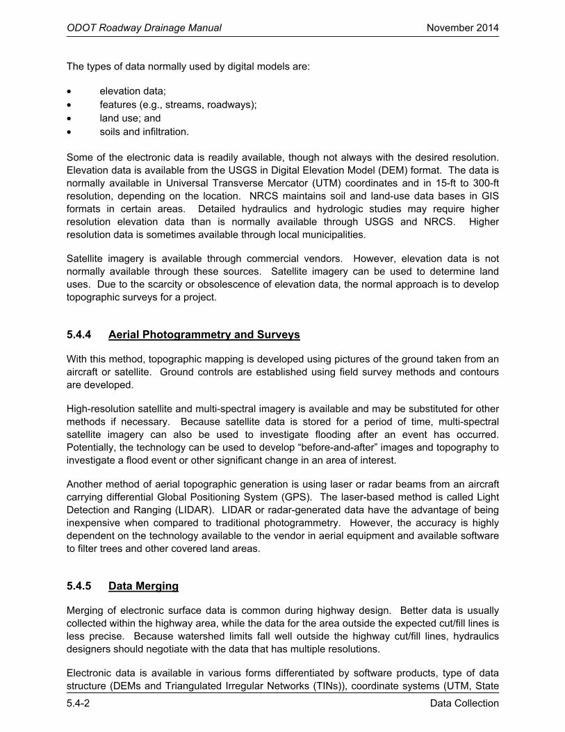
The types of data normally used by digital models are:
• elevation data; • features (e.g., streams, roadways); • land use; and • soils and infiltration. Some of the electronic data is readily available, though not always with the desired resolution. Elevation data is available from the USGS in Digital Elevation Model (DEM) format. The data is normally available in Universal Transverse Mercator (UTM) coordinates and in 15-ft to 300-ft resolution, depending on the location. NRCS maintains soil and land-use data bases in GIS formats in certain areas. Detailed hydraulics and hydrologic studies may require higher resolution elevation data than is normally available through USGS and NRCS. Higher resolution data is sometimes available through local municipalities.
Satellite imagery is available through commercial vendors. However, elevation data is not normally available through these sources. Satellite imagery can be used to determine land uses. Due to the scarcity or obsolescence of elevation data, the normal approach is to develop topographic surveys for a project.
5.4.4 Aerial Photogrammetry and Surveys
With this method, topographic mapping is developed using pictures of the ground taken from an aircraft or satellite. Ground controls are established using field survey methods and contours are developed.
High-resolution satellite and multi-spectral imagery is available and may be substituted for other methods if necessary. Because satellite data is stored for a period of time, multi-spectral satellite imagery can also be used to investigate flooding after an event has occurred. Potentially, the technology can be used to develop “before-and-after” images and topography to investigate a flood event or other significant change in an area of interest.
Another method of aerial topographic generation is using laser or radar beams from an aircraft carrying differential Global Positioning System (GPS). The laser-based method is called Light Detection and Ranging (LIDAR). LIDAR or radar-generated data have the advantage of being inexpensive when compared to traditional photogrammetry. However, the accuracy is highly dependent on the technology available to the vendor in aerial equipment and available software to filter trees and other covered land areas.
5.4.5 Data Merging
Merging of electronic surface data is common during highway design. Better data is usually collected within the highway area, while the data for the area outside the expected cut/fill lines is less precise. Because watershed limits fall well outside the highway cut/fill lines, hydraulics designers should negotiate with the data that has multiple resolutions.
Electronic data is available in various forms differentiated by software products, type of data structure (DEMs and Triangulated Irregular Networks (TINs)), coordinate systems (UTM, State

ODOT Roadway Drainage Manual November 2014
Data Collection 5.4-3
Plane, Latitude-Longitude), units (feet or meters), resolution and datums. When merging data in different forms, care should be taken to ensure proper conversion prior to merging. Standardizing all data to the most current format is the best way to ensure compatibility. There are tools available to accomplish the data “translation.”
A more serious issue in data merging is caused by differences in data resolution. For example, a digital surface model developed using a photogrammetric method is typically of a lower resolution compared to a surface model developed using a field data collection survey. When merging the data, elevation differences at the boundaries of the different data areas should be carefully reconciled.
There is often a problem with artificial pits and peaks due to the creation of DEMs and TINs. The data user should evaluate the data and correct these inconsistencies.
5.4.6 Accuracy of Data
In any hydraulics computation, it is important to understand the limitations in the accuracy of the computations based on the accuracy of the input data. In step-backwater computations using the USACE HEC-RAS program, there are several factors that have significant effects on the accuracy of the results:
• accuracy of the survey data, • spacing between cross sections, • correct establishment of upstream and downstream study limits, and • selection of roughness coefficients. Most field surveys of channel and floodplain cross sections are recorded to an accuracy of 0.1 ft. If the survey truly represents the cross sections of the reach of the stream being studied to 0.1-ft accuracy, the greatest accuracy that would result from a step-backwater computation could be no more than 0.1 ft. Any results expressed more precisely than 0.1 ft are simply a function of the mathematics.
The accuracy of aerial survey technology for generating cross sectional coordinate data is governed by mapping industry standards. Cross sections obtained from contours of topographic maps developed by photogrammetric methods are generally not as accurate as those generated from field data collection methods. Aerial photography can supplement field survey cross sections. The use of aerial elevation survey technology permits additional coordinate points and cross sections to be obtained at only a small incremental cost, and the coordinate points may be formatted for direct input into water surface profile computer programs (e.g., HEC-RAS).
For further information on determining the relationships between survey technology and accuracy employed for determining stream cross sectional geometry, degree of confidence in selecting Manning’s roughness coefficients and the resulting accuracy of hydraulic computations, refer to the USACE publication, RD-26, Accuracy of Computer Water Surface Profiles (5). This publication also presents methods of determining the upstream and downstream limits of data collection for a hydraulic study requiring a specified degree of accuracy.

ODOT Roadway Drainage Manual November 2014
5.4-4 Data Collection

ODOT Roadway Drainage Manual November 2014
Data Collection 5.5-1
5.5 FIELD REVIEWS
5.5.1 General
An on-site field review should be made by the project engineer and the hydraulics designer in order for the hydraulics designer to become familiar with the conditions along the project. The most complete survey data cannot adequately depict all site conditions or substitute for personal inspection by someone experienced in drainage design. Factors that most often need to be confirmed by the Roadway Drainage Engineer are:
• verify basin boundaries, • selection of roughness coefficients, • evaluation of apparent flow direction and diversions, • flow concentration, • observation of land use and related flood hazards, • geomorphic relationships, • high-water marks or profiles and related frequencies, • existing structure size and type, • existence of wetlands, and • erosion and scour. An actual visit to the site where the project will be constructed should be made before any detailed hydraulics design is undertaken. This may be combined with the visit by others (e.g., roadway and structural designers, environmental reviewers) and may take the form of an official plan-in-hand/scoping site visit. The hydraulics designer may visit the site separately, however, because of interests that are different from the others and the time needed to obtain the required data.
5.5.2 Preparation of Preliminary Drainage Data
5.5.2.1 Transfer Road Alignment to Quadrangle Map
To prepare for preliminary drainage data collection, the hydraulics designer should first have the project’s road alignment transferred to the appropriate quadrangle map. The Roadway Design Division will provide a preliminary plan and profile for the proposed highway project. To transfer the road alignment, the hydraulics designer should perform the following steps:
1. Obtain the Quadrangle Map.
a. Hard copies of the USG 7.5 minutes quadrangle maps of the State of Oklahoma could be found in ODOT Roadway Design, Survey and Bridge Divisions.
b. USGS maps may be downloaded at no cost at www.store.usgs.gov. The map should be saved in the project file. The downloaded map may then be referenced into the appropriate CADD file and scaled.

ODOT Roadway Drainage Manual November 2014
5.5-2 Data Collection
2. Obtain “Old Plans.” The project’s “Old Plans” for the existing highway can be obtained from ODOT Reproduction or from the originating agency. The old plans may provide other useful hydraulics information for the preliminary hydraulics design.
3. Prepare Preliminary Drainage Map for Preliminary Hydrology/Hydraulics Field Review. Draw the existing drainage crossing locations, proposed highway alignment and existing highway alignment, as needed. Label the proposed highway stationing for each existing crossing.
a. Survey and Preliminary Plans Available in CADD Format. Reference the downloaded USGS map into the CADD file and scale appropriately. Turn on existing drainage structures and existing and proposed highway alignments, as necessary. Turn on existing survey data such as structure type, structure size and flow lines. Label the proposed highway station at each existing structure crossing.
b. Survey and Preliminary Plans that are not Available in CADD Format. Use an engineering scale, typically 1:20, to transfer existing drainage crossing locations and the existing or proposed (if available) highway alignment from the “Old Plans” and from the preliminary plans to the quadrangle map. Use a pencil to label the proposed highway stationing for each crossing.
5.5.2.2 Determine Drainage Areas
Before the field review, determine the drainage area for all drainage crossings within the project limits on the quadrangle map. This calculation will be verified during the field review. The drainage area can be determined using CADD, approved hydraulics software (see Chapter 16 “Hydraulics Software”) or traditional hand methods using planimeter. The drainage area of non-contributing areas should be determined. These area(s) will retain all rainfall from the design event.
The two most common methods used by ODOT for determining the boundary and the area of a small watershed are:
1. The USGS Maps. Printed in 7.5 minutes or 15 minutes quadrangle with 5 ft, 10 ft or 20 ft contour lines. The USGS maps are easy to use, less expensive and most of the time accurate enough for design purposes. Once the boundary of the watershed has been determined, the area of the watershed can be measured with a planimeter. When greater accuracy is required (e.g., small, flat areas), field survey will be more favorable. USGS maps may also be downloaded, referenced into CADD drawings and scaled appropriately. The hydraulics designer may then delineate and calculate the drainage areas within the CADD drawings.
2. The Field Survey Map. Field survey data completed by ODOT Survey Division field crews can be plotted from aerial survey photos. Field survey information is more accurate, the survey effort should be commensurate with the sensitivity or importance of this site. Financial constraints, crew availability, weather and time are factors that can limit the use of field survey.

ODOT Roadway Drainage Manual November 2014
Data Collection 5.5-3
For large watersheds, the boundary and the area of the watershed are best determined using CADD, StreamStats or other digital methods.
The drainage areas and boundaries should be included on the Preliminary Drainage Map for the Preliminary Hydrology/Hydraulics Field Review Meeting.
5.5.2.3 Determine Channel Slopes
Usually, the channel slopes (at the structure site or for the whole watershed as used in the USGS method) can be obtained by measuring it directly on the USGS maps or by Field survey data.
The user may use the engineering scale, the distance-measuring wheel or mapping software to determine the channel lengths.
5.5.3 Conducting the On-Site Inspection
The following questions should be addressed before making the field visit:
• Can any needed information be obtained from maps or aerial photos or by telephone calls?
• What type of equipment should be taken and, most important, what exactly are the critical items at this site?
• Should photos be taken looking upstream and downstream from the site and along the contemplated highway centerline in both directions?
• Should details of the streambed and banks be photographed?
• Are there structures in the vicinity both upstream and downstream?
• Should close-up photographs complete with a scale or grid be taken to facilitate estimates of the streambed gradation?
Use one of the following, as provided in Appendix 5.B, to document the visit:
• Form 1 - Field Visit Investigation Form • Form 2 - Hydraulics Survey Field Inspection Checklist

ODOT Roadway Drainage Manual November 2014
5.5-4 Data Collection
ODOT Roadway Drainage Manual November 2014
Data Collection 5.6-1
5.6 DRAINAGE SURVEY INFORMATION
5.6.1 General
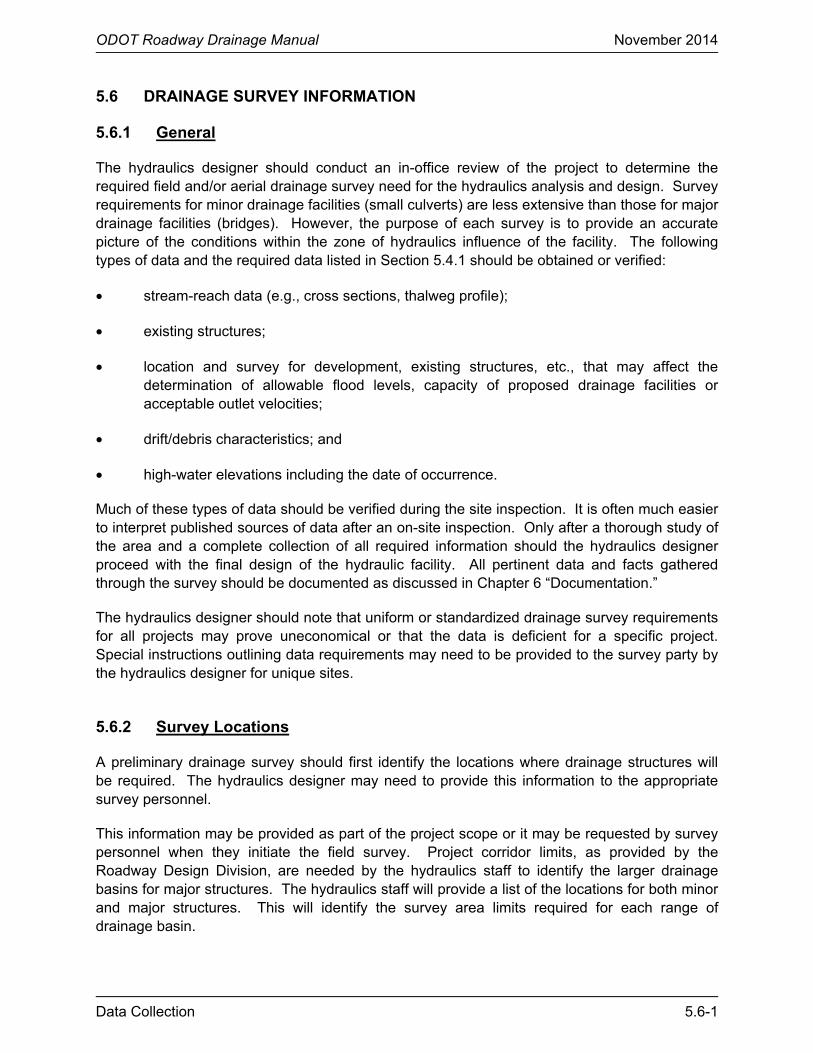
The hydraulics designer should conduct an in-office review of the project to determine the required field and/or aerial drainage survey need for the hydraulics analysis and design. Survey requirements for minor drainage facilities (small culverts) are less extensive than those for major drainage facilities (bridges). However, the purpose of each survey is to provide an accurate picture of the conditions within the zone of hydraulics influence of the facility. The following types of data and the required data listed in Section 5.4.1 should be obtained or verified:
• stream-reach data (e.g., cross sections, thalweg profile);
• existing structures;
• location and survey for development, existing structures, etc., that may affect the determination of allowable flood levels, capacity of proposed drainage facilities or acceptable outlet velocities;
• drift/debris characteristics; and
• high-water elevations including the date of occurrence.
Much of these types of data should be verified during the site inspection. It is often much easier to interpret published sources of data after an on-site inspection. Only after a thorough study of the area and a complete collection of all required information should the hydraulics designer proceed with the final design of the hydraulic facility. All pertinent data and facts gathered through the survey should be documented as discussed in Chapter 6 “Documentation.”
The hydraulics designer should note that uniform or standardized drainage survey requirements for all projects may prove uneconomical or that the data is deficient for a specific project. Special instructions outlining data requirements may need to be provided to the survey party by the hydraulics designer for unique sites.
5.6.2 Survey Locations
A preliminary drainage survey should first identify the locations where drainage structures will be required. The hydraulics designer may need to provide this information to the appropriate survey personnel.
This information may be provided as part of the project scope or it may be requested by survey personnel when they initiate the field survey. Project corridor limits, as provided by the Roadway Design Division, are needed by the hydraulics staff to identify the larger drainage basins for major structures. The hydraulics staff will provide a list of the locations for both minor and major structures. This will identify the survey area limits required for each range of drainage basin.

ODOT Roadway Drainage Manual November 2014
5.6-2 Data Collection
5.6.3 Drainage Survey Needs
The basic information needed for all drainage surveys is as follows:
• Obtain any observed high water (OHW) elevations and the date of the high water. It is important that this information be obtained because it can aid the hydraulics designer in the calibration of the hydraulics model developed to analyze existing and to size future structures.
• For any existing box culvert or large culvert encountered, obtain the flow line (invert or top of floor) elevation and coordinates of the inlet and outlet ends. The coordinates of all four corners should be recorded for box culverts. Additional elevations and coordinates at the end of any apron are optional. This data is important for any crossing, but especially important for any culverts that will be extended.
• Obtain the low elevation of any upstream buildings.
• Obtain data approximately 500 ft both upstream and downstream to define the channel and any obstructions. Dams should always be documented because they may impact the highway crossing. For dams, provide the spillway crest elevation, width and shape.
• When crossing lake bed areas, the lake bed overflow outlet should be located and the overflow elevation established.
• Complete and submit the Drainage Data Information Sheet to the hydraulics designer when the survey for the remainder of the project is transmitted. Appendix 5.B provides sample forms.
.

ODOT Roadway Drainage Manual November 2014
Data Collection 5.7-1
5.7 DATA EVALUATION
5.7.1 Objective
Once the needed data have been collected, the next step is to compile it into a usable format. The hydraulics designer should ascertain whether the data contains inconsistencies or other unexplained anomalies that might lead to erroneous calculations or results. The primary reason for analyzing the data is to draw all of the various pieces of collected information together and to fit them into a comprehensive and accurate representation of the hydrologic and hydraulics characteristics of a particular site.
5.7.2 Reliability
Data should always be subjected to careful study by the hydraulics designer for accuracy and reliability. Experience, knowledge and judgment are important components of data evaluation. It is in this phase that reliable data should be separated from that which is less reliable and historical data combined with that obtained from measurements. The data should be evaluated by the hydraulics designer for consistency and to identify any changes from established patterns. Reviews should be made of such items as previous studies and old plans for types and sources of data, how the data were used and any indications of accuracy and reliability. Historical data should be reviewed to determine whether significant changes have occurred in the watershed and whether these data can be used. Data acquired from the publications of established sources (e.g., USGS) can usually be considered as valid and accurate. Data should always be subjected to careful study by the hydraulics designer for accuracy and reliability.
Basic data (e.g., streamflow data derived from non-published sources) should be evaluated and summarized before use. Compare maps, aerial photographs, Landsat images and land-use studies with one another and with the results of the field survey and resolve any inconsistencies. General references should be consulted to help define the hydrologic character of the site or region under study and to aid in the analysis and evaluation of data.
5.7.3 Sensitivity
Sensitivity studies may be used to evaluate data and establish the relative importance of specific data items to the final design. Sensitivity studies consist of conducting a design with a range of values for specific data items. The effect on the final design can then be established. This is useful in determining what specific data items have major effects on the final design and the importance of possible data errors. Time and effort can then be dedicated to the more sensitive data items ensuring that these data are as accurate as possible. This does not mean that inaccurate data are accepted for less sensitive data items, but it allows prioritization of the data collection process given a limited budget and time allocation.
The results of this type of data evaluation should be used so that as reliable a description as possible of the site can be made within the allotted time and the resources committed to this effort. The effort of data collection and evaluation should be appropriate for the importance and extent of the project and/or facility.

ODOT Roadway Drainage Manual November 2014
5.7-2 Data Collection

ODOT Roadway Drainage Manual November 2014
Data Collection 5.8-1
5.8 REFERENCES
1. AASHTO. Highway Drainage Guidelines. Washington, DC : Technical Committee on Hydrology and Hydraulics, American Association of State Highway and Transportation Officials, 2007.
2. FHWA. Highway Hydrology, Hydraulic Design Series No. 2, 2nd Edition. Washington,
DC : Federal Highway Administration, U.S. Department of Transportation, 2002. FHWA-NHI-02-001.
3. —. Stream Stability at Highway Structures. Hydraulic Engineering Circular No. 20, Third
Edition. Washington, DC : Federal Highway Administration, U.S. Department of Transportation, 2001. FHWA-NHI-01-002.
4. —. River Engineering for Highway Encroachments—Highways in the River Environment.
Hydraulic Design Series No. 6. Washington, DC : Federal Highway Administration, U.S. Department of Transportation, 2001. FHWA-NHI-01-004.
5. USACE. Accuracy of Computer Water Surface Profiles. Davis, CA : Hydrologic
Engineering Center, U.S. Army Corps of Engineers, 1986. RD-26.

ODOT Roadway Drainage Manual November 2014
5.8-2

ODOT Roadway Drainage Manual November 2014
Data Collection 5.A-1
APPENDIX A DATA SOURCES
A.1 PRINCIPLE WATERSHED DATA SOURCES
• Meteorological Data National Oceanography and Atmospheric Agency (NOAA) Climatic Data Center Ashville, North Carolina 28801
• The Oklahoma Climatological Survey 120 David L. Boren Blvd., Ste. 2900 Norman, Oklahoma 73109-0628 (405) 325-2550
• U.S. Geological Survey – Water Resources Division 202 NW 66 Street, Bldg. 7 Oklahoma City, Oklahoma 73116 (405) 810-4400
• Survey Division – ODOT Surveyed high water marks records
• Hydrology data from others (see below) Local Television Stations – Weather Department
A.2 PRINCIPLE WATERSHED DATA SOURCES
• U.S. Geological Survey Maps (“Quad” Sheets) U.S. Geological Survey Rocky Mountain Mapping Center Stop 504 Denver, Colorado 80225 (303) 236-5829
• EROS Aerial Photographs U.S. Geological Survey EROS Data Center 47914 252nd Street Sioux Falls, South Dakota 57198 (605) 594-6151
• U.S. Geological Survey – Water Resources Division 202 NW 66 Street Oklahoma City, Oklahoma 73116 (405) 231-4256

ODOT Roadway Drainage Manual November 2014
5.A-2 Data Collection
• Maps and Aerial Photos (see ODOT Survey Division) or ○ USDA-ASCS – Aerial Photograph Field Office, P. O. Box 30010, Salt Lake City,
UT 84130-0010, (801) 524-5856
○ National Archives and Records Administration, Cartographic and Architectural Branch. 8601 Adelphi Road, College Park, Maryland 20740 (301) 837-3200
• OK State Department of Libraries Archives Branch 200 NE 18th Street Oklahoma City, Oklahoma 73105
• NRCS and BLM Soils Maps U.S. Department of Agriculture
• Watershed data from others (e.g. counties, cities, municipals)
A.3 PRINCIPLE SITE DATA SOURCES
• ODOT files of aerial drainage surveys • ODOT files for existing facilities • Site visits by hydraulics designer • Field or aerial surveys from others (e.g. counties, cities, municipals)
A.4 PRINCIPLE REGULATORY DATA SOURCES
• Federal Flood Plain delineations and studies Federal Emergency Management Agency Flood Map Service Center PO Box 3617 Oakton, Virginia 22124-9617 (877) 336-2627
• OK State Water Resources Board 600 N. Harvey Avenue Oklahoma City, Oklahoma 73105 (405) 231-2555
• FHWA design criteria and practices (see FHWA website) Federal Highway Administration
• Local ordinance and master plans (counties, cities, municipals)
• Corps of Engineers Section 404 permit program (see Environmental below)

ODOT Roadway Drainage Manual November 2014
Data Collection 5.A-3
• U.S. Coast Guard
• U.S. Environmental Protection Agency (EPA) (see Environmental below)
• OK State Department of Health (see Environmental below)
• Federal Registers (see GPO website)
A.5 PRINCIPLE ENVIRONMENTAL DATA SOURCES
• U.S. Environmental Protection Agency District 6 OK Field Office, 1645 South 101 East Ave., Room 134 Tulsa, Oklahoma 74128
• U.S. Corps of Engineers data and studies Central Oklahoma Area Office 1645 South 101 East Ave. Tulsa, Oklahoma 74128 (918) 669-7366
• U.S. Geological Survey water quality data (see address above)
• OK State Water Resources Board Water quality data (see address above)
• Environmental statements prepared by other Federal, state and local agencies as well as private parties
• Environmental data from others (see below) OK State Department of Health
A.6 PRINCIPLE DEMOGRAPHIC, ECONOMIC AND POLITICAL DATA SOURCES
• Chamber of Commerce • ODOT Planning Division • ODOT Survey Division • Site visits

ODOT Roadway Drainage Manual November 2014
5.A-4 Data Collection
A.7 OTHER DATA SOURCES
• U.S. Bureau of Reclamation (USBR) U.S. Denver Federal Center Denver, Colorado 80225 (303) 236-8098
• U.S. Bureau of Land Management (BLM) 7906 E. 33rd Street, Suite 101 Tulsa, Oklahoma 74145 (918) 621-4100
• Region 6 – U.S. Environmental Protection Agency (EPA) 1445 Ross Avenue, Suite 1200 Dallas, Texas 75202-2733 (214) 655-7175
• Region 6 – U.S. Federal Emergency Management Agency (FEMA) FRC 800 North Loop 288 Denton, Texas 76209-3698 (940) 898-5399
• U.S. Fish and Wildlife Services (USFWS) Southwest Region 500 Gold Avenue SW Albuquerque, New Mexico 87102 (505) 248-6931
• U.S. Forest Services (USFS) Southwest Region 333 Broadway SE Albuquerque, New Mexico 87102 (504) 842-3198
• National Resources Conservation Service (NRCS) USDA, NRCS 100 USDA, Suite 206 Stillwater, Oklahoma 74074 (405) 742-1204
• U.S. Corps of Engineers (USACE)
Southwestern Division U.S. Army Engineer District 1645 South 101 East Avenue Tulsa, Oklahoma 74128 (918) 669-7366

ODOT Roadway Drainage Manual November 2014
Data Collection 5.A-5
• Regional and State U.S. Geological Survey (USGS) (see above address)
• Federal Highway Administration (FHWA) 5801 N Robinson Ave, Suite 300 Oklahoma City, Oklahoma 73118 (405) 254-3300
• National Oceanic and Atmospheric Administration (NOAA) National Weather Service (NWS) Southern Region Headquarters819 Taylor Street, Room 10A06 Ft. Worth, Texas 76102 (817) 325-3620

ODOT Roadway Drainage Manual November 2014
5.A-6 Data Collection

ODOT Roadway Drainage Manual November 2014
Data Collection 5.B-1
APPENDIX B FIELD INVESTIGATION FORMS
ODOT Roadway Drainage Manual November 2014
5.B-2 Data Collection
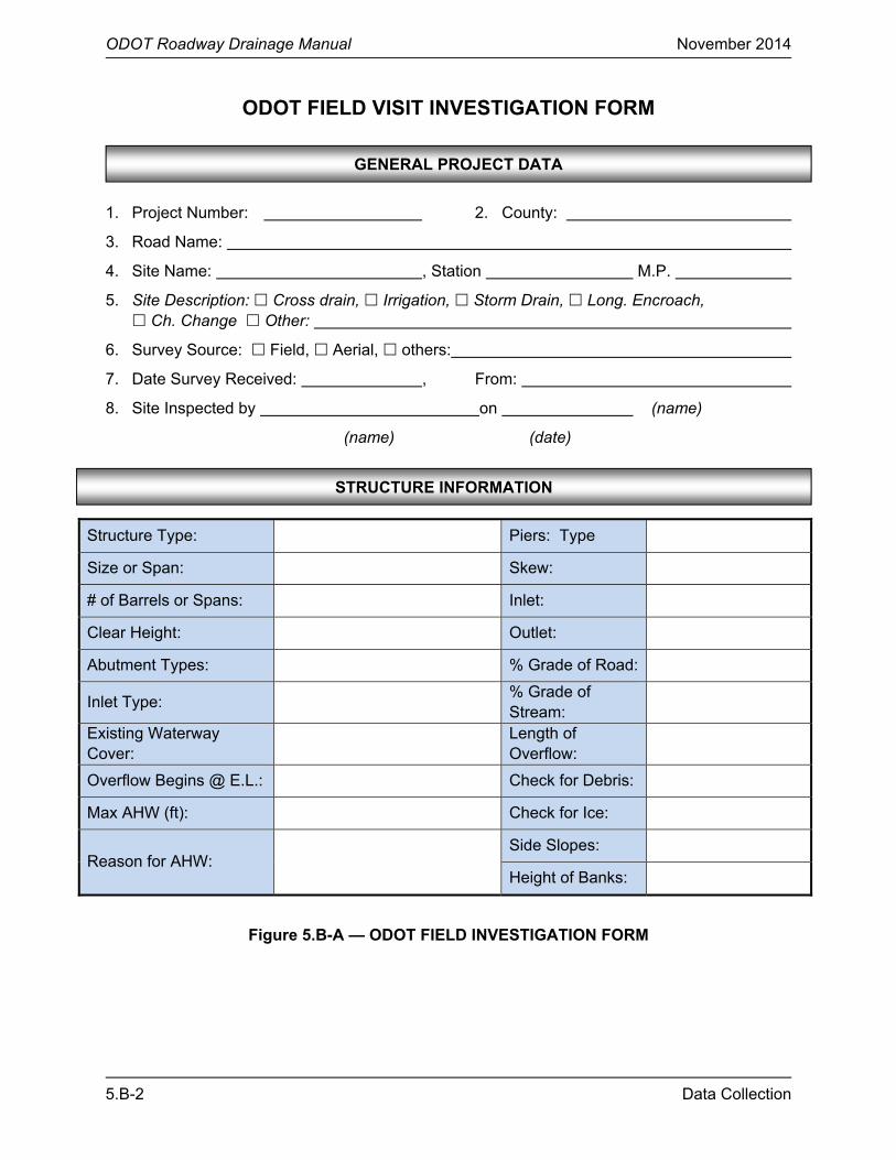
ODOT FIELD VISIT INVESTIGATION FORM 1. Project Number: 2. County:
3. Road Name:
4. Site Name: , Station M.P.
5. Site Description: Cross drain, Irrigation, Storm Drain, Long. Encroach, Ch. Change Other:
6. Survey Source: Field, Aerial, others:
7. Date Survey Received: , From:
8. Site Inspected by on (name)
(name) (date)
Structure Type: Piers: Type
Size or Span: Skew:
# of Barrels or Spans: Inlet:
Clear Height: Outlet:
Abutment Types: % Grade of Road:
Inlet Type: % Grade of Stream:
Existing Waterway Cover:
Length of Overflow:
Overflow Begins @ E.L.: Check for Debris:
Max AHW (ft): Check for Ice:
Reason for AHW: Side Slopes:
Height of Banks:
Figure 5.B-A — ODOT FIELD INVESTIGATION FORM
STRUCTURE INFORMATION
GENERAL PROJECT DATA

ODOT Roadway Drainage Manual November 2014
Data Collection 5.B-3
Up or Downstream Restriction:
Outlet Channel, Base:
Manning’s n Value:
Type of Material in Stream:
Ponding:
Check Bridges Upstream and Downstream:
Yes No Current Mapping Status:
Check Land Use Upstream and Downstream:
Yes No Identify:
Survey Required? Yes No
Remarks:
Figure 5.B-A — ODOT FIELD INVESTIGATION FORM (Continued)
CHANNEL INFORMATION

ODOT Roadway Drainage Manual November 2014
5.B-4 Data Collection
ODOT HYDRAULICS SURVEY FIELD INSPECTION CHECKLIST 1. Project Number: 2. County: 3. Road Name: 4. Site Name: , Station M.P. 5. Site Description: Cross drain, Irrigation, Storm Drain, Long. Encroach,
Ch. Change Other: 6. Survey Source: Field, Aerial, others: 7. Date Survey Received: , From: 8. Site Inspected by on (name) (date)
1. Reviewed:
Aerial Photos: Yes, Photo #s , None Available Mapping/Maps: Yes, Map #s , None Available Reports: Yes, No, None Available at this time ((Agency)) Permanent File: Yes, No, No file data found 2. Special Requirements and Problems Identified for Field Checking:
Hydrologic Boundary: obtain hydrologic channel geometry Adverse Flood History: obtain HW Marks/dates/eyewitness Irrigation Ditch: obtain several Water Right depths Permits Required: USACE, Ch. Change, Dam, USCG, NFIP, Dr. District Other: Adverse Channel Stability and Alignment History: Check for headcutting, bank caving, braiding
increased meander activity Structure Scour: check flow alignment, scour at culvert outlet or evidence of bridge scour Obtain bed/bank material samples at (The following details obtained at the site are annotated on the Drainage Survey) 1. Survey appears correct: Yes, Apparent errors are:
that were resolved by:
2. Flooding Apparent? No Yes, HW marks obtained, Yes, but HW marks not obtained because
3. Do all Floods Reach Site? Yes, No, details obtained, No, but details not obtained because
Figure 5.B-B — ODOT HYDRAULICS SURVEY FIELD INVESTIGATION CHECKLIST
GENERAL PROJECT DATA
OFFICE PREPARATION FOR INSPECTION
FIELD INSPECTION

ODOT Roadway Drainage Manual November 2014
Data Collection 5.B-5
4. Do floodwaters enter irrigation ditch? N/A No, Yes, details obtained Yes, but details not obtained because
5. Hydrologic Ch. Geometry obtained? Yes, No because
6. Channel Unstable? No, Yes, because of headcutting observed and amount/location obtained, bank caving, braiding, increased meander activity, Other
7. Structure Scour in Evidence? No, Minor, Yes and obtained bed/bank samples and noted any flow alignment problems, Yes and bed/bank material samples not obtained and flow alignment not noted because
8. Irrigation facility? No, Yes, several water right related depths obtained, Yes, no water right related depths obtained because
9. Manning’s n obtained? Yes, No, because
10. Property damage due to BW? No Yes, elevation/property type checked, Yes, but elevation/property type not obtained because
11. Environmental Hazards Present? No, Yes, details obtained, Yes, details not obtained because
12. Ground Photos Taken? Upstream floodplain and all property, Downstream floodplain and all property, Site looking from downstream, Site looking from upstream, Channel material w/scale, Evidence of channel instability, Evidence of scour, Existing structure inlet/outlet, Other
13. Effective drainage area visually verified? Yes, No, because
1. Section II Findings annotated on survey? Yes, No, see section attached (attach typed
explanation by site station and site name and check list section and number). 2. Survey Originals and check lists forwarded to ((Agency’s Roadway Unit, ea. site’s))
and the ((Agency’s Hydraulics Unit, ea. site’s)) for hydraulic design. /s/ ((Hydraulics Designer Making Inspection))
Figure 5.B-B — ODOT HYDRAULICS SURVEY FIELD INVESTIGATION CHECKLIST (Continued)
POST INSPECTION SURVEY ANNOTATION

ODOT Roadway Drainage Manual November 2014
5.B-6 Data Collection