Chapter 4B Objectives Developing an ER Diagram Converting the E-R Diagram to a Relational Schema (...
6
1 Chapter 4B Objectives • Understand – How ERD components affect database design and implementation – That real-world database design often requires the reconciliation of conflicting goals 1 CS275 Fall 2010 Developing an ER Diagram • Database design is an iterative process • Building an ERD includes the following: 1. Create detailed narrative of organization’s description of operations 2. Identify business rules based on description of operations 3. Identify main entities and relationships from business rules 4. Develop initial ERD 5. Identify attributes and primary keys that adequately describe entities 6. Review and revise the ERD 2 CS275 Fall 2010 Developing an E-R Model • Information Gathering/Preliminary Investigation – interviewing the end users – examining the business forms and reports. – Write results/description of the investigation • Determine Entities – ‘things’ you want to collect, keep, or know • Create general rules governing relationships among Entities – Relationship Rules come from the Business Rules of the organization – Result will help define all foreign keys 3 CS275 Fall 2010 Refining an E-R Model • M:N Relationship – Convert the M:N relationship to a composite (bridge) entity consisting of the parent tables’ primary keys. • 1:M Relationships – Create the foreign key by putting the primary key of the “one” in the table of the “many”. • “One” -- Parent table • “Many” -- Dependent table – Define Relationship Participation: • Both sides are MANDATORY. • Both sides are OPTIONAL. • One side is OPTIONAL and one side is MANDATORY. 4 CS275 Fall 2010
Transcript of Chapter 4B Objectives Developing an ER Diagram Converting the E-R Diagram to a Relational Schema (...

1
Chapter 4B Objectives
• Understand
– How ERD components affect database design and
implementation
– That real-world database design often requires the
reconciliation of conflicting goals
1CS275 Fall 2010
Developing an ER Diagram
• Database design is an iterative process
• Building an ERD includes the following:
1. Create detailed narrative of organization’s description of operations
2. Identify business rules based on description of operations
3. Identify main entities and relationships from business rules
4. Develop initial ERD
5. Identify attributes and primary keys that adequately describe entities
6. Review and revise the ERD2CS275 Fall 2010
Developing an E-R Model
• Information Gathering/Preliminary Investigation
– interviewing the end users
– examining the business forms and reports.
– Write results/description of the investigation
• Determine Entities
– ‘things’ you want to collect, keep, or know
• Create general rules governing relationships
among Entities
– Relationship Rules come from the Business Rules
of the organization
– Result will help define all foreign keys3CS275 Fall 2010
Refining an E-R Model
• M:N Relationship
– Convert the M:N relationship to a composite (bridge) entity consisting of the parent tables’ primary keys.
• 1:M Relationships
– Create the foreign key by putting the primary key of the “one” in the table of the “many”.
• “One” -- Parent table
• “Many” -- Dependent table
– Define Relationship Participation:
• Both sides are MANDATORY.
• Both sides are OPTIONAL.
• One side is OPTIONAL and one side is MANDATORY.
4
CS275 Fall 2010
2
Refining an E-R Model
• Weak Entity
– Put the key of the parent table (strong entity) in the weak entity.
– The weak entity relationship conforms to the same rules as the 1:M relationship, except foreign key restrictions.
• 1:1 Relationships
– If both entities are in mandatory participation in the relationship and they do not participate in other relationships, it is most likely that the two entities should be part of the same entity.
5
CS275 Fall 2010
Developing an ERD
Tiny College Example
• Tiny College – needs a data base to keep it’s
information.
• Define Business rules & determine Data Entities
– Tiny College is divided into several schools
• Each school is composed of several departments.
• Each school is administered by a dean. A 1:1
relationship exists between DEAN and SCHOOL.
• Each dean is a member of a group of administrators
(ADMINISTRATOR). Deans also hold professorial
rank and may teach a class (PROFESSOR).
6CS275 Fall 2010
Developing an ER Diagram
• Tiny College Business Rules (cont.)
– Each school is composed of several departments.
• The smallest number of departments operated by a
school is one, and the largest number of
departments is indeterminate (N).
• Each department belongs to only a single school.
• Each department may offer courses
– Each department may have many professors
assigned to it
• Each professor may teach up to four classes; each
class is section of course
7CS275 Fall 2010
Developing an ER Diagram
• Business Rules(cont.)– Each department has several students
• Each student has only a single major and is
associated with a single department
– Each student has an advisor in his or her
department• Each advisor counsels several students
– Student may enroll in several classes, but (s)he
takes each class only once during any given
enrollment period
– A class is taught in a room and the room in the
building
8CS275 Fall 2010

3
Developing an ER Diagram
9CS275 Fall 2010
Developing an ER Diagram
10CS275 Fall 2010
Developing an ER Diagram
11CS275 Fall 2010
Developing an ER Diagram
12CS275 Fall 2010
4
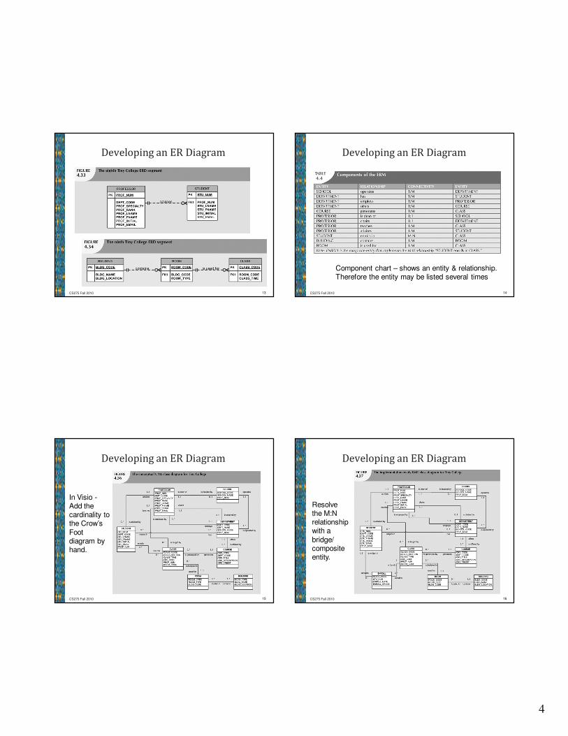
Developing an ER Diagram
13CS275 Fall 2010
Developing an ER Diagram
14CS275 Fall 2010
Component chart – shows an entity & relationship. Therefore the entity may be listed several times
Developing an ER Diagram
15CS275 Fall 2010
In Visio -Add the cardinality to the Crow’s
Foot diagram by hand.
Developing an ER Diagram
16CS275 Fall 2010
Resolve the M:N relationship with a
bridge/ composite entity.

5
Converting the E-R Diagram to a Relational
Schema ( from Chen ERD)
• Summary of Tiny College’s Entities and Attributes
17
CS275 Fall 2010
Created for
diagram
styles like
Chen which
do not list
attributes.
ER Diagram Models
18CS275 Fall 2010
Database Design Challenges:
Conflicting Goals
• Database designers must make design compromises
– Conflicting goals: design standards, processing speed, information requirements
• Important to meet logical requirements and design conventions
• Design is of little value unless it delivers all specified query and reporting requirements
• Some design and implementation problems do not yield “clean” solutions
19CS275 Fall 2010
ER Diagram Homework Hints
• Interpreting the Business Rules
– Find Major grouping of Data - NOUNS
– Find Major relationships between Data - VERBS
– Verify with the User/Client
• Understructured (high-level conceptual view)
– Decompose any M:N relationships
– Review/verify business rules against relational
schema
• How could it be represented in the form
Table(PrimeKey, Attribute2, Atribute3,….)
20
CS275 Fall 2010
6
ER Diagram Homework Hints
• Overly structured
– example: Patient Appointment-relationship verbs, sees doctor, sees nurse, has xray,….etc.
– Delete verbs that will not represent any new or different data sets. Be Careful!
• Cardinality
– Vocalize the numbers in relationship to the box it is on. That is why there are cardinality symbols at each end of the relationship. “This box representing an Invoice can have one to ten line items” (1,10) “This employee may or may not belong to a department” (0,1)
21
CS275 Fall 2010
ER Diagram Homework Hints
• Mandatory vs Non-mandatory
– Must be stated in the Business rules
– Look for statements like “roving employees not
attached to a project/department” or “may have”
(implies may not have)
– Where cardinality is (0,x)on one side/entity there
will be the � symbol on the relationship on the
other side/entity.
• Multi-valued attributes
– Flexibility vs effeciency
22
CS275 Fall 2010
Summary
• M:N relationship is valid at conceptual level
– Must be mapped to a set of 1:M relationships
• ERDs may be based on many different ERMs
• UML class diagrams are used to represent the
static data structures in a data model
• Database designers are often forced to make
design compromises
23CS275 Fall 2010