Chapter 4 Soft Ground Treatment Works - JICAChapter 4 Soft Ground Treatment Works 4 - 4 (2)...
203
Chapter 4 Soft Ground Treatment Works
Transcript of Chapter 4 Soft Ground Treatment Works - JICAChapter 4 Soft Ground Treatment Works 4 - 4 (2)...
Chapter 4
Soft Ground Treatment Works
Soft Ground Treatment Manual
4 - 1
4-1 Concept of Design and Execution of Soft Ground Treatment
4-1-1 Outline of Soft Ground Treatment
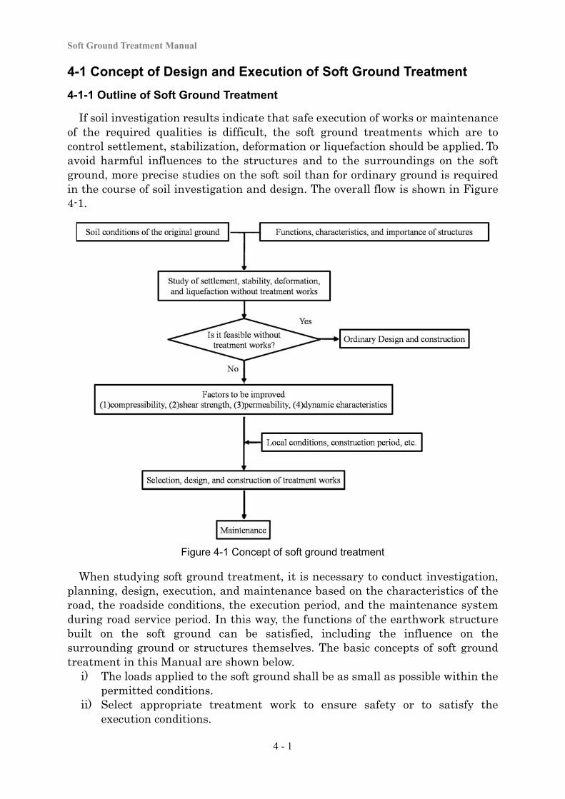
If soil investigation results indicate that safe execution of works or maintenance of the required qualities is difficult, the soft ground treatments which are to control settlement, stabilization, deformation or liquefaction should be applied. To avoid harmful influences to the structures and to the surroundings on the soft ground, more precise studies on the soft soil than for ordinary ground is required in the course of soil investigation and design. The overall flow is shown in Figure 4-1.
Figure 4-1 Concept of soft ground treatment
When studying soft ground treatment, it is necessary to conduct investigation, planning, design, execution, and maintenance based on the characteristics of the road, the roadside conditions, the execution period, and the maintenance system during road service period. In this way, the functions of the earthwork structure built on the soft ground can be satisfied, including the influence on the surrounding ground or structures themselves. The basic concepts of soft ground treatment in this Manual are shown below.
i) The loads applied to the soft ground shall be as small as possible within the permitted conditions.
ii) Select appropriate treatment work to ensure safety or to satisfy the execution conditions.
Chapter 4 Soft Ground Treatment Works
4 - 2
iii) An improvement method that utilizes the inherent characteristics of the ground shall be given a precedence in the study of the preloading method or slow loading method to enhance the strength through consolidation by ensuring sufficient time for execution.
iv) Conduct design and execution while considering the limitations of current investigation/analysis techniques, and the uncertainty of investigation, design, and execution.
v) Conduct adequate execution management and information management based on an understanding of the complicated characteristics and distribution of soft ground.
vi) Conduct appropriate design and execution considering the ability of maintenance to ensure the intended performance of the earthwork structure.
4-1-2 Significant Points of Soft Ground Treatment
Significant points in the implementation of soft ground treatment are presented below. a. Conformity with the purpose of usage: The function of earthwork structure
constructed on soft ground must fulfill for traffics on the structures. It also includes the serviceability of the structure for the safety and comfort of the road users.
b. Reliability: An earthwork structure on soft ground has appropriate safety against various types of influences, such as from traffics, rainfall, and seismic motion.
c. Durability: Even an earthwork structure in aging deterioration after long usage should keep original quality and structural safety.
d. Quality Control: Earthwork structures should be constructed securely in order to ensure the purpose of usage, safety of the structures and safe execution of works. The structures should be studied carefully in the design stage.
e. Easiness of maintenance: Easiness of maintenance such as daily inspection, examination of the materials and repair work should be considered. It is related to durability and economic efficiency.
f. Harmony with the environment: Earthwork structures on the soft ground should be harmonized with the social and natural environment, and apply an appropriate landscape to the surrounding area.
g. Economic efficiency: It is important to reduce the total cost including for maintenance and repairs to minimize the life cycle cost rather than simply minimizing the construction cost.
Soft Ground Treatment Manual
4 - 3
4-2 Selection of Soft Ground Treatment Method
4-2-1 Effects of Soft Ground Treatment
There are various kind of soft ground treatment method as shown in Figure 4-1. The purposes of treatment works are;
- control of settlement, - retention of stability, - control of deformation of the surrounding ground, - control of liquefaction-induced damage, and - retention of trafficability.
Since each treatment work method is based on its own fundamental principles, it is important to select an appropriate treatment work method that matches the reason why such treatment is necessary and the purpose of the treatment.
(1) Settlement Control
From the viewpoint of the serviceability of a road embankment, the main issue is residual settlement during road service period. And another issue is the amount of total settlement to estimate the necessary volume of the embankment and to estimate the effect on the surrounding ground. Methods to reduce residual settlement during road service period include securing the maximum progress of consolidation during construction to minimize residual settlement during road service period, and reducing total settlement to correspondingly reduce residual settlement during road service period.
Secure maximum progress of consolidation during construction
Treatment methods designed to secure maximum progress of consolidation during construction include the vertical drain method, in which drain materials are installed in the vertical direction in the soft soil layer at appropriate intervals to reduce the consolidation drainage distance in the lateral direction in order to accelerate consolidation. In addition, surcharge methods include constructing an embankment in advance to accelerate consolidation. If the work period is sufficiently long, residual settlement can be reduced by using a slow banking method, which involves spending a long time to construct an embankment.
Reduce total settlement
Methods to reduce total settlement include those designed to reduce the embankment load on the soft layer in order to reduce the amount of settlement of the ground. For example, common methods include supporting the embankment load using soil-improving piles, which are constructed in a soft soil layer by the compaction method or deep mixed method, and using lightweight materials for embankment materials in order to reduce the load and the consolidation stress. When a soft soil layer is thin, the excavation replacement method is sometimes adopted, in which a consolidated layer is replaced with good-quality soil.
Chapter 4 Soft Ground Treatment Works
4 - 4
(2) Stabilization
Soft ground treatment work is studied when it is considered to be necessary based on the results of the studies described in 3-2-3. Embankments will collapse because of a lack of strength in the foundation ground or a lack of strength in the embankment material. This Manual concentrates on embankment failure due to a lack of strength in the foundation ground, not in the embankment material. Measures to secure ground stability are generally divided into a number of types: using consolidation to increase the strength of the soft ground, using soft soil improvement to increase the resistance of the ground, and reducing slip sliding force.
Increasing the strength of the soft ground with consolidation
The intention of this process is to secure the stability of a soft layer against slips by increasing the strength of the ground with efficient consolidation and drainage of the soft layer. Specific measures used in this process are mostly the same as those for the methods to accelerate consolidation settlement. Another typical method is the slow banking method in which an embankment is slowly built up.
Increase in the resistance with soft soil treatment
The intention of this process is to increase the resistance of the foundation ground with soft soil improvement. Resistance is increased by replacing a soft soil layer with good quality soil, constructing compaction piles or improved bodied in a soft soil layer, and installing geotextiles or wire nets in the soft ground or embankment. As a measure against slip failure, in the counterweight filling method, the main embankment is reinforced by constructing another smaller embankment on the side.
Reduction of slip sliding force
The intention of this process is to secure stability against slips by reducing the slip sliding force resulting from the application of the embankment load. Specific measures include the use of a lightweight material for embankment.
(3) Control of Deformation of the Surrounding Ground
Carrying out treatment work is studied when soft ground treatment is considered to be necessary based on the results of the studies described in “3-6 Deformation of the Ground around Earthwork Structures”. When an embankment is constructed on soft ground, lateral deformation due to shear deformation can occur in the ground in addition to consolidation settlement. Refer to “3-2-1 Basic Matters on Design” for the detailed description of the mechanism. Measures to withstand deformation of the surrounding ground are meant to control shear deformation or consolidation deformation. Measures to withsand deformation of the surrounding ground are necessary when harmful deformation occurs to buildings, water channels, underground facilities, or other structures located close to the embankment. Anti-deformation measures are also necessary when an existing embankment is likely to suffer settlement or major deformation
Soft Ground Treatment Manual
4 - 5
due to the pulling force of additional embankment on the side of an existing embankment. Anti-deformation measures for the surrounding ground are divided into interception of stress and reduction of stress.
Interception of stress
This is a method to prevent stress occurring due to the application of the embankment load from reaching the surrounding ground, in order to control deformation in the surrounding ground. Specific actions taken under this method include;
a. driving structures (e.g., sheet piles) into the soft ground at the slope toe of the embankment,
b. constructing consolidated bodies in the ground in order to realize soft soil improvement, and
c. excavating a soft soil layer, if the layer is thin, in order to replace the soft soil with good-quality soil.
Reduction of stress
This is a method to reduce stress occurring due to the application of the embankment load, in order to reduce settlement of the embankment and reduce the amount of deformation in the surrounding ground. Specific actions taken under this method include the use of a lightweight material for embankment to reduce the embankment load, and distributing support of the embankment load with improvement piles formed in the ground with the compaction method, deep mixed method, etc., in order to reduce stress occurring in the soft layer.
(4) Control of Liquefaction-induced Damage
Carrying out treatment work is studied when soft ground treatment is considered to be necessary based on the results of the studies. In soft ground, as inertial force is added to the ground in an earthquake, the sliding force rapidly increases and the shear resistance of the ground is reduced. Particularly when liquefaction occurs in loose saturated sandy soil ground, the damage can be so great that the embankment will not be able to maintain its original form at all. For cohesive soil ground, on the other hand, liquefaction as serious as that in sandy soil ground rarely occurs, but the action of inertial force can cause deformation of the embankment or the foundation ground and affect buildings and facilities in the vicinity. Liquefaction of sandy soil ground that will cause particularly serious damage and related countermeasures are explained below. Anti-liquefaction works are largely divided according to their theory into;
- control of the occurrence of liquefaction, and - control of deformation after liquefaction.
Methods to control the occurrence of liquefaction are divided according to their action principles into;
- quality treatment of the ground, - increasing effective stress,
Chapter 4 Soft Ground Treatment Works
4 - 6
- dispersing excess pore water pressure, and - controlling shear deformation.
Methods to control liquefaction
a. Ground improvement
This is a process to control the occurrence of liquefaction by increasing shear strength by increasing the density of the soil, chemically stabilizing the structure of the soil, or replacing the easily liquefiable layer itself with a hard-to-liquefy material.
b. Increasing effective stress
This is a process to control the occurrence of liquefaction by increasing the effective stress in the soil to prevent elevation of the excess pore water pressure ratio.
c. Dispersion of excess pore water pressure
This is a process to control the occurrence of liquefaction by constructing highly water-permeable materials in the ground to quickly disperse excess pore water pressure that occurs in an earthquake. The drain method is often used for this process, However, this method is mainly for the purpose of dispersing excess pore water pressure in the event of an earthquake, and its water permeability is very high compared with the abovementioned vertical drain method (which is mainly used in measures to withstand settlement or stability), and thus it is treated separately.
d. Controlling shear deformation
This is a process to control the occurrence of liquefaction by constructing improved bodies or structures with high shear rigidity in the soil, in order to reduce shear deformation occurring in the ground due to seismic motion.
Methods that allow liquefaction, and suppress post-liquefaction deformation
There are methods for mitigating damage due to liquefaction that allow liquefaction to occur in the surrounding ground while controlling the settlement or deformation of earthwork structures like embankments. Specifically, these methods include;
- supporting the embankment with pile foundations, - sheet pile cofferdam at the slope toe of the embankment, - control of settlement or deformation with counterweight filling, and - geotextile reinforcement of the soil.
Methods to control deformation of an embankment due to liquefaction of the embankment itself include geotextile reinforcement of the soil and counterweight filling.
Soft Ground Treatment Manual
4 - 7
Method for deciding anti-liquefaction improvement measures
In many cases, the improvement measures used to meet with the liquefaction of an embankment are selected by stability analysis that assumes a circular slip with generation of excess pore water pressure taken into account. It has been pointed out, however, that this stability analysis method can produce extremely safe-side calculation results. Considering this, it is necessary to select improvement measures based on the use of appropriate techniques.
(5) Retention of Trafficability
When construction machines are run on soft ground, the work efficiency can vary significantly depending on the type of soil or water content. For cohesive soil ground with high water content, etc., due to remolding it can become impossible to run equipment on the ground. In order to conduct work on soft ground like this, it is necessary to secure the necessary trafficability according to the construction machines to be used. Specific methods that are often used include subsurface water drainage, sand mats, shallow soil stabilization, laying of materials, and other methods designed to increase the shear strength of layers relatively closer to the surface.
Chapter 4 Soft Ground Treatment Works
4 - 8
4-2-2 List of Soft Ground Treatment Methods
Tables 4-1a, 4-1b, 4-1c, 4-1d, 4-1e shows all soft ground treatment methods introduced in the manual.
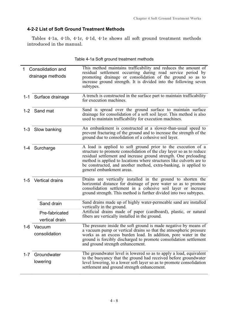
Table 4-1a Soft ground treatment methods
1 Consolidation and
drainage methods
This method maintains trafficability and reduces the amount of residual settlement occurring during road service period by promoting drainage or consolidation of the ground so as to increase ground strength. It is divided into the following seven subtypes.
1-1 Surface drainage A trench is constructed in the surface part to maintain trafficability for execution machines.
1-2 Sand mat Sand is spread over the ground surface to maintain surface drainage for consolidation of a soft soil layer. This method is also used to maintain trafficability for execution machines.
1-3 Slow banking An embankment is constructed at a slower-than-usual speed to prevent fracturing of the ground and to increase the strength of the ground due to consolidation of a cohesive soil layer.
1-4 Surcharge A load is applied to soft ground prior to the execution of a structure to promote consolidation of the clay layer so as to reduce residual settlement and increase ground strength. One preloading method is applied to locations where structures like culverts are to be constructed, and another method, extra-banking, is applied to general embankment areas.
1-5 Vertical drains Drains are vertically installed in the ground to shorten the horizontal distance for drainage of pore water so as to promote consolidation settlement in a cohesive soil layer or increase ground strength. This method is further divided into two subtypes.
Sand drain Sand drains made up of highly water-permeable sand are installed vertically in the ground.
Pre-fabricated
vertical drain
Artificial drains made of paper (cardboard), plastic, or natural fibers are vertically installed in the ground.
1-6 Vacuum
consolidation
The pressure inside the soft ground is made negative by means of a vacuum pump or vertical drains so that the atmospheric pressure works as an excess burden load. In addition, pore water in the ground is forcibly discharged to promote consolidation settlement and ground strength enhancement.
1-7 Groundwater
lowering
The groundwater level is lowered so as to apply a load, equivalent to the buoyancy that the ground had received before groundwater level lowering, to a lower soft layer so as to promote consolidation settlement and ground strength enhancement.
Soft Ground Treatment Manual
4 - 9
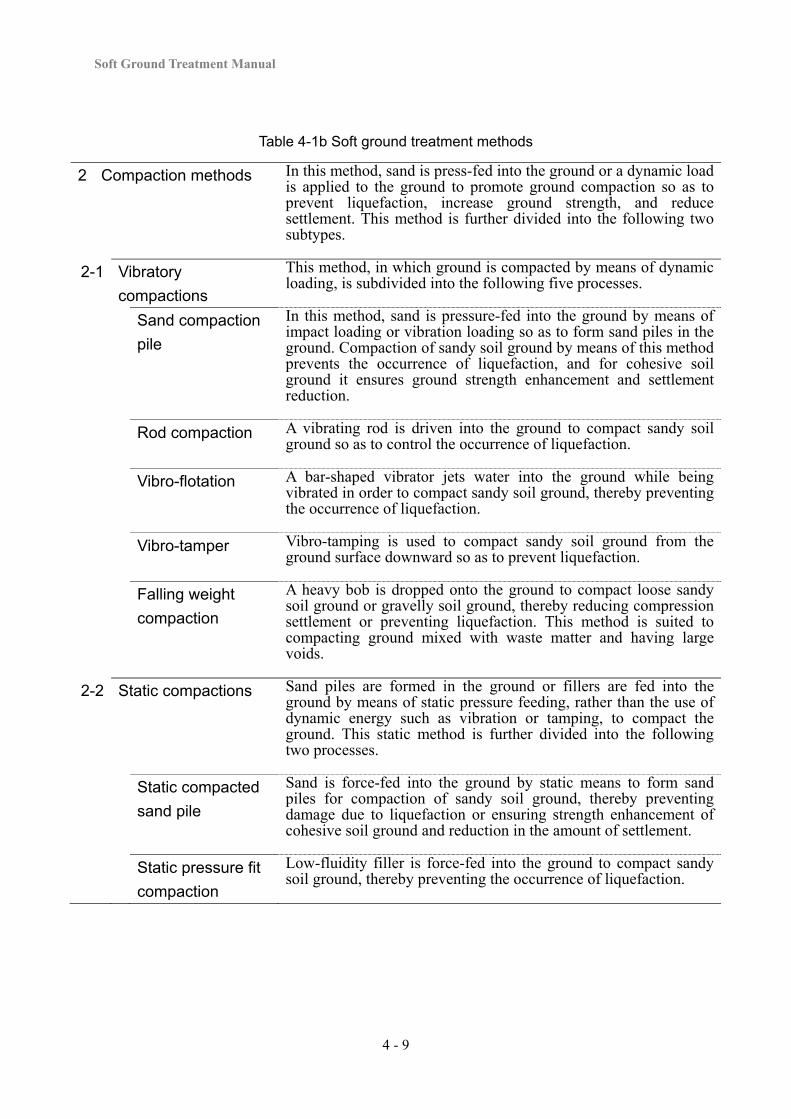
Table 4-1b Soft ground treatment methods
2 Compaction methods In this method, sand is press-fed into the ground or a dynamic load is applied to the ground to promote ground compaction so as to prevent liquefaction, increase ground strength, and reduce settlement. This method is further divided into the following two subtypes.
2-1 Vibratory
compactions
This method, in which ground is compacted by means of dynamic loading, is subdivided into the following five processes.
Sand compaction
pile
In this method, sand is pressure-fed into the ground by means of impact loading or vibration loading so as to form sand piles in the ground. Compaction of sandy soil ground by means of this method prevents the occurrence of liquefaction, and for cohesive soil ground it ensures ground strength enhancement and settlement reduction.
Rod compaction A vibrating rod is driven into the ground to compact sandy soil ground so as to control the occurrence of liquefaction.
Vibro-flotation A bar-shaped vibrator jets water into the ground while being vibrated in order to compact sandy soil ground, thereby preventing the occurrence of liquefaction.
Vibro-tamper Vibro-tamping is used to compact sandy soil ground from the ground surface downward so as to prevent liquefaction.
Falling weight
compaction
A heavy bob is dropped onto the ground to compact loose sandy soil ground or gravelly soil ground, thereby reducing compression settlement or preventing liquefaction. This method is suited to compacting ground mixed with waste matter and having large voids.
2-2 Static compactions Sand piles are formed in the ground or fillers are fed into the ground by means of static pressure feeding, rather than the use of dynamic energy such as vibration or tamping, to compact the ground. This static method is further divided into the following two processes.
Static compacted
sand pile
Sand is force-fed into the ground by static means to form sand piles for compaction of sandy soil ground, thereby preventing damage due to liquefaction or ensuring strength enhancement of cohesive soil ground and reduction in the amount of settlement.
Static pressure fit
compaction
Low-fluidity filler is force-fed into the ground to compact sandy soil ground, thereby preventing the occurrence of liquefaction.
Chapter 4 Soft Ground Treatment Works
4 - 10
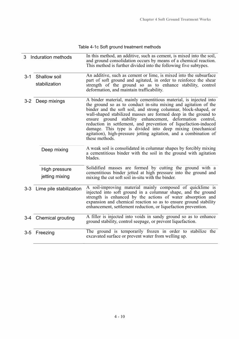
Table 4-1c Soft ground treatment methods
3 Induration methods In this method, an additive, such as cement, is mixed into the soil, and ground consolidation occurs by means of a chemical reaction. This method is further divided into the following five subtypes.
3-1 Shallow soil
stabilization
An additive, such as cement or lime, is mixed into the subsurface part of soft ground and agitated, in order to reinforce the shear strength of the ground so as to enhance stability, control deformation, and maintain trafficability.
3-2 Deep mixings
A binder material, mainly cementitious material, is injected into the ground so as to conduct in-situ mixing and agitation of the binder and the soft soil, and strong columnar, block-shaped, or wall-shaped stabilized masses are formed deep in the ground to ensure ground stability enhancement, deformation control, reduction in settlement, and prevention of liquefaction-induced damage. This type is divided into deep mixing (mechanical agitation), high-pressure jetting agitation, and a combination of these methods.
Deep mixing A weak soil is consolidated in columnar shapes by forcibly mixing a cementitious binder with the soil in the ground with agitation blades.
High pressure
jetting mixing
Solidified masses are formed by cutting the ground with a cementitious binder jetted at high pressure into the ground and mixing the cut soft soil in-situ with the binder.
3-3 Lime pile stabilization
A soil-improving material mainly composed of quicklime is injected into soft ground in a columnar shape, and the ground strength is enhanced by the actions of water absorption and expansion and chemical reaction so as to ensure ground stability enhancement, settlement reduction, or liquefaction prevention.
3-4 Chemical grouting A filler is injected into voids in sandy ground so as to enhance ground stability, control seepage, or prevent liquefaction.
3-5 Freezing The ground is temporarily frozen in order to stabilize the excavated surface or prevent water from welling up.
Soft Ground Treatment Manual
4 - 11
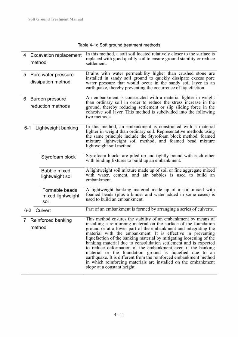
Table 4-1d Soft ground treatment methods
4 Excavation replacement
method
In this method, a soft soil located relatively closer to the surface is replaced with good quality soil to ensure ground stability or reduce settlement.
5 Pore water pressure
dissipation method
Drains with water permeability higher than crushed stone are installed in sandy soil ground to quickly dissipate excess pore water pressure that would occur in the sandy soil layer in an earthquake, thereby preventing the occurrence of liquefaction.
6 Burden pressure
reduction methods
An embankment is constructed with a material lighter in weight than ordinary soil in order to reduce the stress increase in the ground, thereby reducing settlement or slip sliding force in the cohesive soil layer. This method is subdivided into the following two methods.
6-1 Lightweight banking In this method, an embankment is constructed with a material lighter in weight than ordinary soil. Representative methods using the same principle include the Styrofoam block method, foamed mixture lightweight soil method, and foamed bead mixture lightweight soil method.
Styrofoam block Styrofoam blocks are piled up and tightly bound with each other with binding fixtures to build up an embankment.
Bubble mixed lightweight soil
A lightweight soil mixture made up of soil or fine aggregate mixed with water, cement, and air bubbles is used to build an embankment.
Formable beads mixed lightweight soil
A lightweight banking material made up of a soil mixed with foamed beads (plus a binder and water added in some cases) is used to build an embankment.
6-2 Culvert Part of an embankment is formed by arranging a series of culverts.
7 Reinforced banking
method
This method ensures the stability of an embankment by means of installing a reinforcing material on the surface of the foundation ground or at a lower part of the embankment and integrating the material with the embankment. It is effective in preventing liquefaction of the banking material by mitigating loosening of the banking material due to consolidation settlement and is expected to reduce deformation of the embankment even if the banking material or the foundation ground is liquefied due to an earthquake. It is different from the reinforced embankment method in which reinforcing materials are installed on the embankment slope at a constant height.

Chapter 4 Soft Ground Treatment Works
4 - 12
Table 4-1e Soft ground treatment methods
8 Structural methods Structural methods are methods in which structures or materials higher in shear strength or rigidity than soils are constructed in or on the ground to reduce the total settlement of a cohesive soil layer, ensure the stability of the embankment, and reduce stress in the ground. There are four major methods, as follows.
8-1 Counterweight filling The stability of an embankment is maintained by backing up the side of the embankment proper with a smaller embankment.
8-2 Contiguous wall An embankment is surrounded by cast-in-site reinforced concrete (a continuous underground wall), and, in addition, continuous underground walls are constructed at appropriate intervals in a grid pattern inside the surrounding array of reinforced concrete so as to control shear deformation in an earthquake and prevent liquefaction-induced damage.
8-3 Sheet pile Sheet piles are installed in the ground in the lateral direction of the embankment so as to form a continuous wall in order to ensure embankment stability, control lateral deformation of the ground, or prevent liquefaction-induced damage.
8-4 Pile Piles are driven into the ground to transfer the loads of the embankment to the foundation ground, thereby reducing total settlement, ensuring ground stability, controlling deformation due to stress reduction, and preventing liquefaction-induced damage.
9 Laying reinforced
material method
In this method, reinforcing materials are laid under sand mats as temporary work to maintain trafficability. This compacts the sand mats and controls loosening of the soil due to consolidation settlement, thereby mitigating damage due to liquefaction of the banking materials during an earthquake.
Soft Ground Treatment Manual
4 - 13
4-2-3 Applicability of Each Method
The main conditions to take into account in selecting soft ground treatment work methods are the theory and effects of the method, road conditions, ground conditions, work conditions, and economic efficiency.
(1) Principles and Effects of Treatment Works
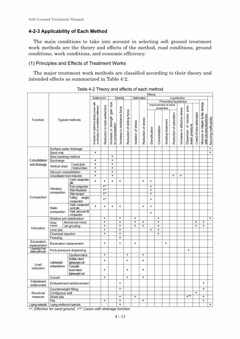
The major treatment work methods are classified according to their theory and intended effects as summarized in Table 4-2.
Table 4-2 Theory and effects of each method
Function Typical methods
EffectsSettlement Stability Deformation Liquefaction
Sec
urin
g tr
affic
abili
ty
Redu
ctio
n in
set
tlem
ent d
urin
g se
rvice
with
ac
cele
ratio
n of
con
solid
atio
n se
ttlem
ent
Red
uctio
n in
tota
l set
tlem
ent
Incr
ease
in
stre
ngth
gai
n du
e to
con
solid
atio
n
Incr
ease
in r
esis
tanc
e fo
rce
Red
uctio
n of
slid
ing
forc
e
Isol
atio
n of
str
ess
Red
uctio
n of
str
ess
Preventing liquefaction
Mea
sure
s to
mitig
ate
facil
ity d
amag
e w
hile
tole
ratin
g liq
uefa
ctio
n
Improvement of sand properties
Incr
ease
in e
ffect
ive
stre
ss
Dis
pers
ion
of
exce
ss
pore
w
ater
pre
ssur
e
Con
trol o
f she
ar d
efor
mat
ion
Den
sific
atio
n
Con
solid
atio
n
Gra
ding
trea
tmen
t
Red
uctio
n of
sat
urat
ion
Consolidation and drainage
Surface water drainage +Sand mat + +Slow banking method + Surcharge + +
Vertical drain Sand drain + + Vertical drain + +
Vacuum consolidation + + Groundwater level reduction + + + +
Compaction
Vibratory compaction
Sand compaction pile + + + + + +
Rod compaction +* + Vibro-floatation +* + Vibro-tamper +* + Falling weight compaction
+* +
Static compaction
Static compacted sand pile + + + + + + Static pressure-fit compaction +
Induration
Shallow soil stabilization + + + + +Deep mixed
Mechanical mixed + + + + + + +Jet grouting + + + + + + +
Lime pile + + + + Chemical injection + + + Freezing +
Excavation replacement
Excavation replacement + + + +
Lowering Pore water pressure Pore-pressure dispersing +
Load reduction
Lightweight embankment
Styrofoam block + + + Bubble-mixed lightweight soil
+ + +
Formable bead-mixed lightweight soil
+ + +
Culvert + + + Embankment reinforcement Embankment reinforcement + +
Structural measure
Counterweight filling + +Contiguous wall + Sheet pile + + +** +Pile + + + +
Laying materials Laying reinforced materials + ++*; Effective for sand ground, +**; Cases with drainage function
Chapter 4 Soft Ground Treatment Works
4 - 14
Even if the same work method is selected, if it is applied for a different purpose and use, the design method will be different. Each method has its own intended effects, and in many cases, a method has major effects, which are its primary purpose, as well as associated secondary effects. For instance, when the sand compaction method is applied to cohesive soil ground, the expected major effects include a reduction in total settlement due to stress distribution with sand piles and, as a safety measure, an increase in slip resistance. A number of secondary effects can also be expected including acceleration of consolidation and reduction of stress as a solution for preventing lateral deformation. Considering these characteristics, a single method can have two or more effects as shown in Table 4-2.
(2) Road Conditions
Methods applicable to a specific project vary depending on the road conditions (e.g., the shape or location of the road embankment) and ground conditions (e.g., the geological composition or soil properties). Road condition items to take into account in selecting treatment methods include (a) the shape (structure) of the longitudinal or transverse cross-section of the road embankment, and (b) the location of the road embankment (whether or not it is at an approach section).
Shape of the longitudinal or transverse cross-section of the road embankment
The shape of an embankment (e.g., the proposed height or width) is an important element in selecting treatment methods. For example, if the proposed height of an embankment is high and the ground stability is a concern, the use of the surcharge method will be limited. In other words, larger stress spreads to a greater depth as the embankment width or height increases, and thus there is a higher possibility of slips or settlement for a deep cohesive soil layer. Therefore, the combined use of other methods is often considered in these cases. For a low embankment, unevenness on the road surface can occur during road service period as the soft ground receives traffic loads. Regarding the embankment section, special caution is necessary for low embankments as well as cut and bank sections, an embankment on an inclined foundation, or a work site adjacent to an existing structure. Problems and corresponding examples are shown in “4-2-5 Applicability of Treatment Methods at Peculiar Places”.
Location of road embankment
For an ordinary section of a road, even if residual settlement is somewhat large, it will not become a problem for the evenness of the pavement if uneven settlement is not large. At an approach to a structure, however, residual settlement itself causes a level difference, and this becomes a problem for vehicles running on the road. In addition, if the stability of an embankment is insufficient, there will be large earth pressure on the abutment, and problems can occur including lateral movement of the abutment, etc. Therefore, measures for settlement and stability at an approach section are very important. Problems and corresponding examples are shown in “4-2-5 Applicability of Treatment Methods at Peculiar Places”.
Soft Ground Treatment Manual
4 - 15
(3) Ground Conditions
1) Soil properties
Sandy soil ground
Sand or sandy soil has larger particles than cohesive soil, but the void ratio is smaller. Sandy soil also has good water permeability, and there are few problems with sandy soil ground regarding ordinary actions. However, since there is a fear of liquefaction occurring in a loose sandy soil layer due to the actions of seismic motion, it is necessary to conduct checking as specified by “3-2-7 Stability against Seismic Ground Motion” and study measures according to the results.
Cohesive soil ground
Because of the soil properties of cohesive soil ground, soft ground treatment work is often necessary. Some cohesive soils have a high sensitivity ratio and suffer a drastic decline in strength once they are disturbed. Therefore, the treatment requires selecting methods that disturb the ground as little as possible. Caution is also necessary as methods based on the same principles show different patterns of ground disturbance depending on the implementation procedure.
Peaty ground
Peat layers often have high compressibility, water content exceeding 300%, and extremely small initial strength. Their permeability, however, is often very high, and settlement due to primary consolidation rapidly progresses even without the use of consolidation accelerating methods (e.g., the vertical drain method). Because strength reinforcement can be expected with the progress of consolidation, the slow banking method is an effective method for these soils. Muck has low permeability and often has water content of less than about 300%. There is a severe drop in strength once its structure is disturbed, and so an increase in strength due to consolidation cannot be expected. Therefore, the surcharge method, which causes a minor degree of ground disturbance, can be used to cope with settlement, while the overweight fill method can be used to secure stability. However, these methods tend to become very large in scale.
2) Geological composition
Shallow and thin soft layer
When a soft layer is shallow and thin, its consolidation settlement is small and ends in a short time. In general, it is also less subject to slip failure. Therefore, the treatment of these layers is often conducted with a simple subsurface water drainage method. When constructing a very important structure, it is relatively easy to excavate and remove the problem soft layer. Thus, the excavation replacement method is also often used.
Thick soft layer
When a soft layer is thick, the subsurface water drainage method is used in combination with other methods according to the purpose of application or the soil
Chapter 4 Soft Ground Treatment Works
4 - 16
properties. However, for extremely thick soft layers, it is not only difficult but also uneconomical to apply the vertical drain method or sand compaction pile method to every layer. Therefore, the standard procedure in this case would be to use the above methods to a certain depth and leave the remaining part untreated or jointly use the surcharge method. With long vertical drains, the seepage resistance of the draining material is large if the material has a small cross-section, and due to consolidation delay it will not show the effect expected by the theory. This point needs to be kept in mind as described in “4-3-5”.
Thin soft layer (less than 3-4m) sandwiched between draining layers
In many cases, settlement due to consolidation rapidly progresses because of a short consolidation drainage distance, and it can be expected that the increase in strength will be sufficient. Therefore, treatment of these layers is often conducted with the subsurface water drainage method, slow banking method, or surcharge method. In some cases, if sand layers are continuous, even those that are only about 5 cm in thickness, they can be effective as draining layers. If the sand layers are not continuous, they will not serve as effective draining layers, and this requires attention.
Thick soft layer lacks draining layer (sand layer)
Since the distance for consolidation drainage is long, it takes a long time to accelerate consolidation settlement, and no rapid increase in strength is expected. Settlement measures are thus often conducted with the vertical drain method, which accelerates consolidation. Stability acceleration is then often realized by using the counterweight filling method, slow banking method, sand compaction pile method, induration method, or lightweight embankment method, either singly or in combination.
Thick sand layer (4 m or more) at shallow depth underlain by soft cohesive layer
When the embankment is low, in general there will be no stability-related problems, and only settlement will cause problems. Settlement measures are generally conducted with the vertical drain method or surcharge method. Although the vacuum loading method or groundwater lowering method work to increase consolidation loads, caution is necessary regarding the maintenance of vacuum pressure or the impact of groundwater lowering on the surrounding area during execution. When sand layers have accumulated in a loose condition, caution is required regarding the occurrence of liquefaction in a major earthquake.
Soft layer on inclined foundation
Application examples are described in “4-2-5 Applicability of Treatment Methods at Peculiar Places”
Soft Ground Treatment Manual
4 - 17
(4) Work Conditions
In selecting treatment work methods, items to be considered regarding work conditions include work period, materials, trafficability for construction machinery, the execution depth, and impacts on the surrounding area.
Work period
This is an extremely important item in the selection of treatment work methods. There are many cases in which a relatively economical method will be sufficient if the work period is long enough. In other words, when the work period is long, it is often possible to construct an embankment while maintaining stability with the slow banking method, and residual settlement will be minimized by leaving the work site for a long time. When vertical drains or sand compaction piles are installed, long installation spacing can be maintained, or the driving length can be reduced. Thus, a long work period produces various advantages. Therefore, when deciding the work period for soft ground treatment in a road project, the basic rule is to first secure a sufficient period for the treatment, and to select appropriate treatment work methods according to the available work period.
Materials
Since it has recently become difficult to obtain highly permeable sea sand or river sand, points to consider in selecting appropriate treatment work methods should include the easiness or economic efficiency of acquiring materials for each method.
Trafficability for construction machinery
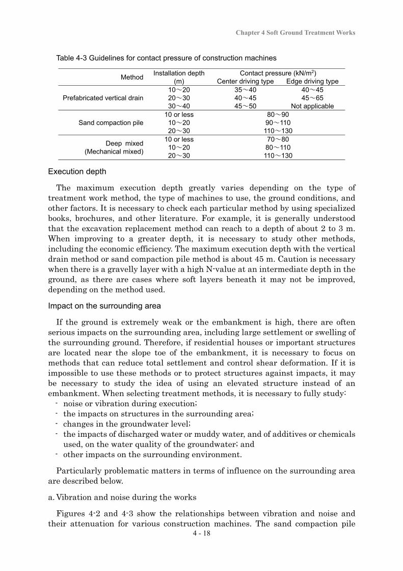
It is necessary to guarantee sufficient trafficability for construction machinery when soft ground is improved. Therefore, a combined use of the sand mat method and shallow soil stabilization method is often adopted. In order to secure trafficability, the sand mat thickness is generally decided by considering the weight of the construction machines, the contact pressure, and the strength of the subsurface section of the soft ground as described in 4-3-2 for details. Table 4-3 shows guideline values for contact pressure for machines used in the prefabricated vertical drain method, sand compaction pile method, and deep mixed method.
For the prefabricated vertical drain method, “Center driving type” means that the casing is set at the center of the construction machine, while “Edge driving type” means that the casing is set on either side of the construction machine.
Chapter 4 Soft Ground Treatment Works
4 - 18
Table 4-3 Guidelines for contact pressure of construction machines
Method Installation depth
(m) Contact pressure (kN/m2)
Center driving type Edge driving type
Prefabricated vertical drain 10~20 35~40 40~45 20~30 40~45 45~65 30~40 45~50 Not applicable
Sand compaction pile 10 or less 80~90
10~20 90~110 20~30 110~130
Deep mixed (Mechanical mixed)
10 or less 70~80 10~20 80~110 20~30 110~130
Execution depth
The maximum execution depth greatly varies depending on the type of treatment work method, the type of machines to use, the ground conditions, and other factors. It is necessary to check each particular method by using specialized books, brochures, and other literature. For example, it is generally understood that the excavation replacement method can reach to a depth of about 2 to 3 m. When improving to a greater depth, it is necessary to study other methods, including the economic efficiency. The maximum execution depth with the vertical drain method or sand compaction pile method is about 45 m. Caution is necessary when there is a gravelly layer with a high N-value at an intermediate depth in the ground, as there are cases where soft layers beneath it may not be improved, depending on the method used.
Impact on the surrounding area
If the ground is extremely weak or the embankment is high, there are often serious impacts on the surrounding area, including large settlement or swelling of the surrounding ground. Therefore, if residential houses or important structures are located near the slope toe of the embankment, it is necessary to focus on methods that can reduce total settlement and control shear deformation. If it is impossible to use these methods or to protect structures against impacts, it may be necessary to study the idea of using an elevated structure instead of an embankment. When selecting treatment methods, it is necessary to fully study:
- noise or vibration during execution; - the impacts on structures in the surrounding area; - changes in the groundwater level; - the impacts of discharged water or muddy water, and of additives or chemicals
used, on the water quality of the groundwater; and - other impacts on the surrounding environment.
Particularly problematic matters in terms of influence on the surrounding area are described below.
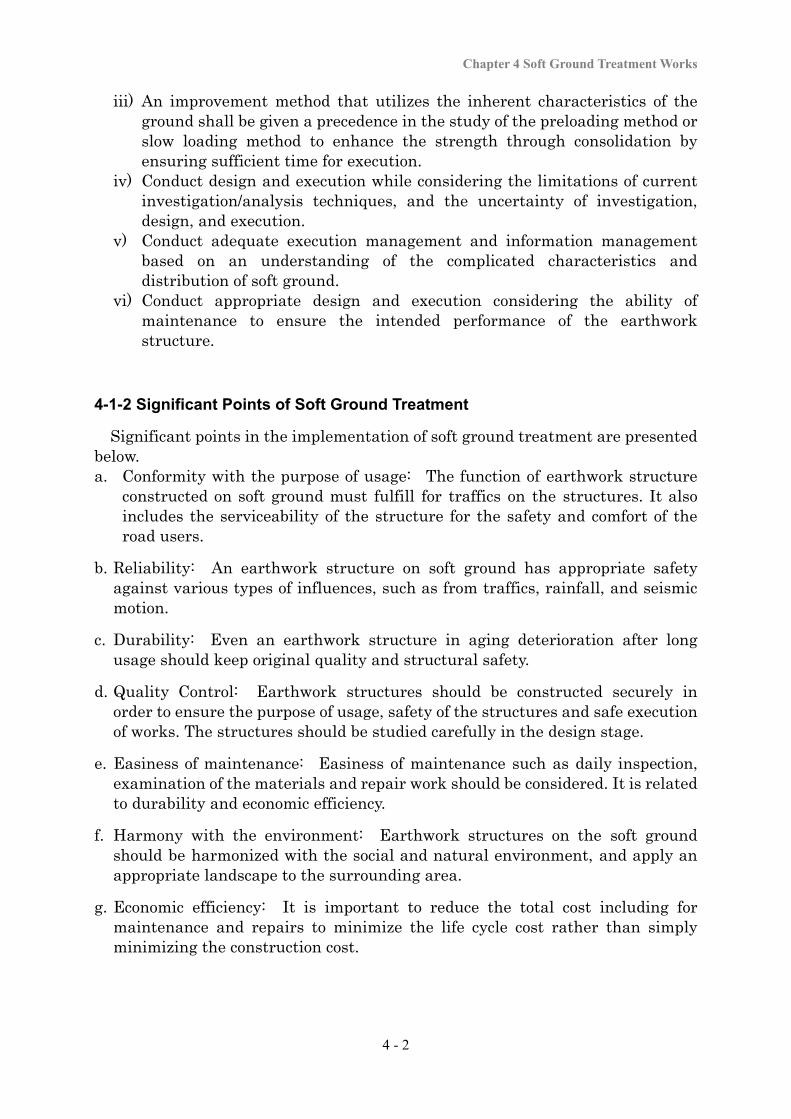
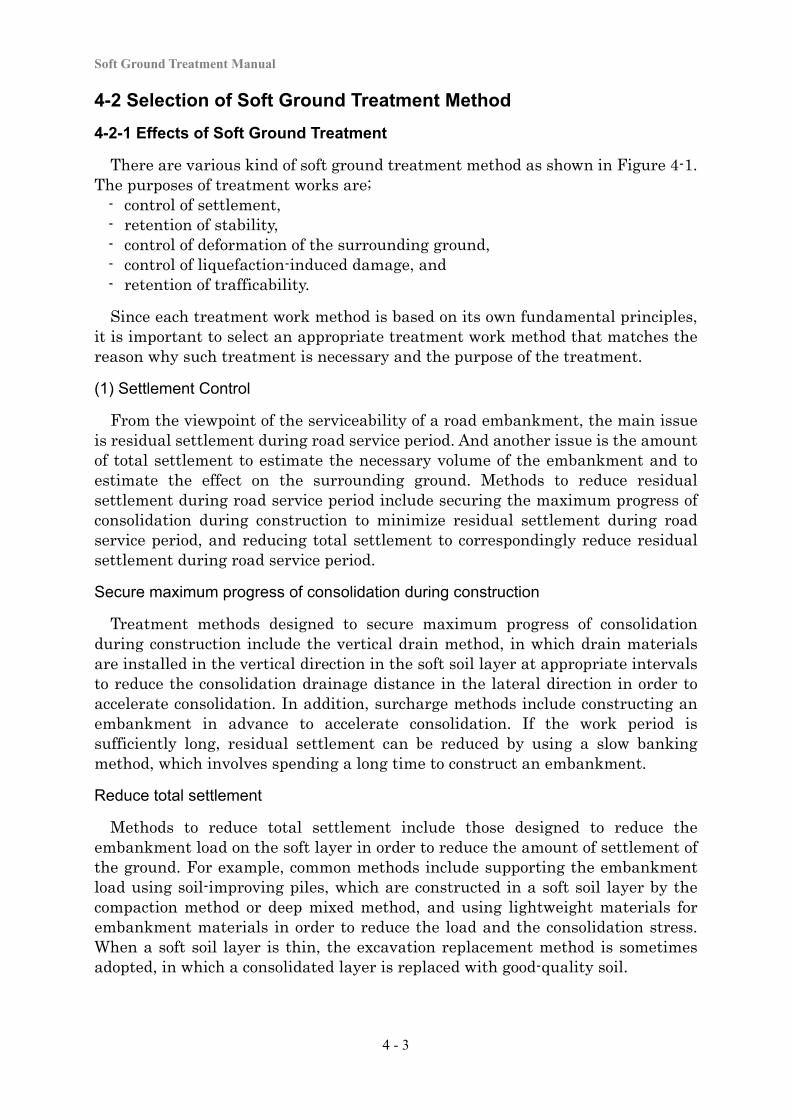
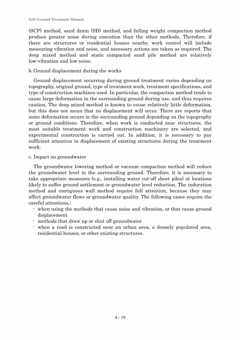
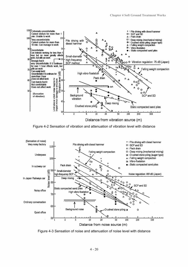
a. Vibration and noise during the works
Figures 4-2 and 4-3 show the relationships between vibration and noise and their attenuation for various construction machines. The sand compaction pile
Soft Ground Treatment Manual
4 - 19
(SCP) method, sand drain (SD) method, and falling weight compaction method produce greater noise during execution than the other methods. Therefore, if there are structures or residential houses nearby, work control will include measuring vibration and noise, and necessary actions are taken as required. The deep mixed method and static compacted sand pile method are relatively low-vibration and low-noise.
b. Ground displacement during the works
Ground displacement occurring during ground treatment varies depending on topography, original ground, type of treatment work, treatment specifications, and type of construction machines used. In particular, the compaction method tends to cause large deformation in the surrounding ground during use, and thus requires caution. The deep mixed method is known to cause relatively little deformation, but this does not mean that no displacement will occur. There are reports that some deformation occurs in the surrounding ground depending on the topography or ground conditions. Therefore, when work is conducted near structures, the most suitable treatment work and construction machinery are selected, and experimental construction is carried out. In addition, it is necessary to pay sufficient attention to displacement of existing structures during the treatment work.
c. Impact on groundwater
The groundwater lowering method or vacuum compaction method will reduce the groundwater level in the surrounding ground. Therefore, it is necessary to take appropriate measures (e.g., installing water cut-off sheet piles) at locations likely to suffer ground settlement or groundwater level reduction. The induration method and contiguous wall method require full attention, because they may affect groundwater flows or groundwater quality. The following cases require the careful attentions,;
- when using the methods that cause noise and vibration, or that cause ground displacement
- methods that draw up or shut off groundwater - when a road is constructed near an urban area, a densely populated area,
residential houses, or other existing structures.
Chapter 4 Soft Ground Treatment Works
4 - 20
Figure 4-2 Sensation of vibration and attenuation of vibration level with distance
Figure 4-3 Sensation of noise and attenuation of noise level with distance
Soft Ground Treatment Manual
4 - 21
4-2-4 Selection of the Method
The followings are necessary to consider for selecting soil treatment methods. - performance required of the structure - purpose of treatment - characteristics of the soil - land use restrictions - impacts on the work period and the surrounding area - effectiveness and economic efficiency.
In the selection flow, the top priority of study is placed on the sand mat and similar methods to secure trafficability. If any problems arise regarding settlement or stability, then methods that involve slowly building up the embankment and that are relatively inexpensive (e.g., surcharge or the slow banking method), are preferably studied. Suitable methods are studied based on the theory and effects of each method as shown in Table 4-2. If the use of only the surcharge method might not solve a settlement-related problem because of strict time constraints, the use of the only the slow banking method will not be able to maintain sufficient stability, or the filling works could cause deformation or other damage to facilities in the vicinity. In selecting appropriate treatment methods, a number of promising methods are selected based on the study of the road conditions, ground conditions, work conditions, and records of past application on similar types of ground, as described in “(3) Conditions to consider in selecting soft ground treatment work methods”. An initial design is then carried out for these methods to calculate the rough cost, and the most suitable method is selected based on a comprehensive point of view. If the cost of the soft ground treatment work is expected to be very high, it is necessary to conduct an extensive study, including changing the road structure or route, taking into account economic efficiency, road standards, etc.
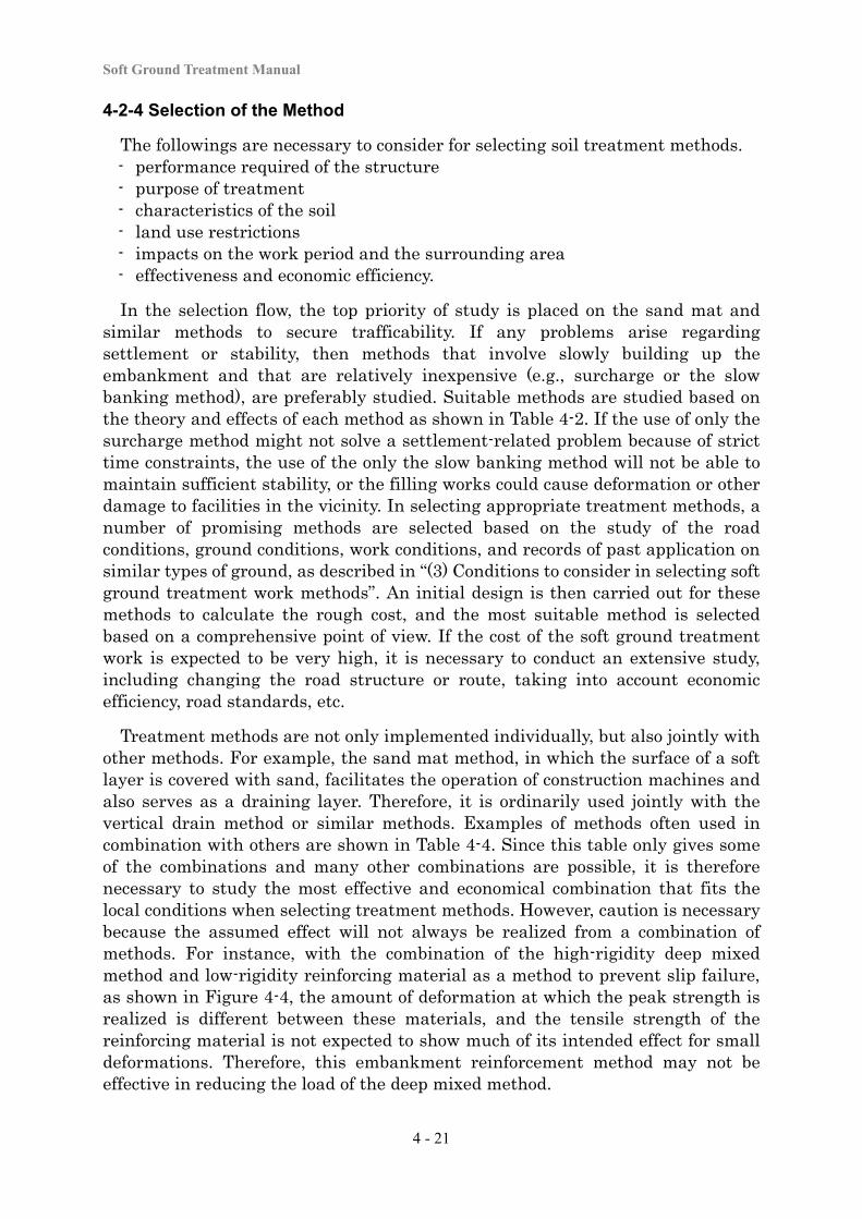
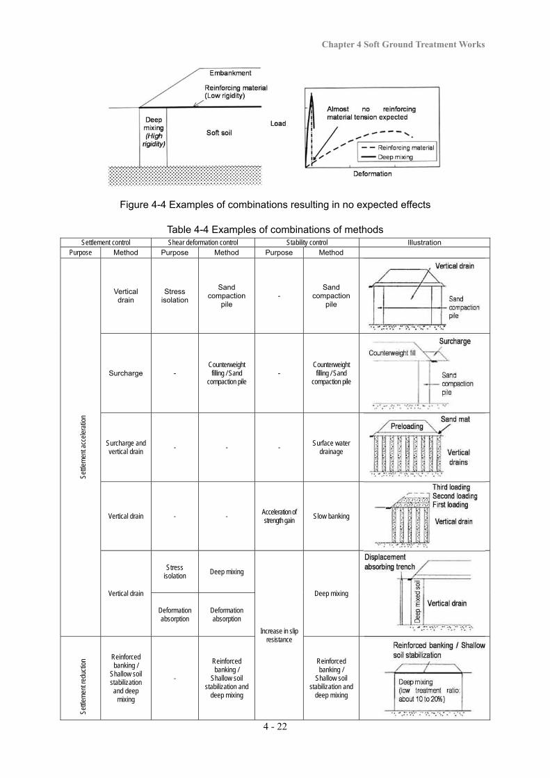
Treatment methods are not only implemented individually, but also jointly with other methods. For example, the sand mat method, in which the surface of a soft layer is covered with sand, facilitates the operation of construction machines and also serves as a draining layer. Therefore, it is ordinarily used jointly with the vertical drain method or similar methods. Examples of methods often used in combination with others are shown in Table 4-4. Since this table only gives some of the combinations and many other combinations are possible, it is therefore necessary to study the most effective and economical combination that fits the local conditions when selecting treatment methods. However, caution is necessary because the assumed effect will not always be realized from a combination of methods. For instance, with the combination of the high-rigidity deep mixed method and low-rigidity reinforcing material as a method to prevent slip failure, as shown in Figure 4-4, the amount of deformation at which the peak strength is realized is different between these materials, and the tensile strength of the reinforcing material is not expected to show much of its intended effect for small deformations. Therefore, this embankment reinforcement method may not be effective in reducing the load of the deep mixed method.
Chapter 4 Soft Ground Treatment Works
4 - 22
Figure 4-4 Examples of combinations resulting in no expected effects
Table 4-4 Examples of combinations of methods Settlement control Shear deformation control Stability control Illustration
Purpose Method Purpose Method Purpose Method
Settl
emen
t acc
eler
atio
n
Vertical drain
Stress isolation
Sand compaction
pile -
Sand compaction
pile
Surcharge - Counterweight filling / Sand
compaction pile -
Counterweight filling / Sand
compaction pile
Surcharge and vertical drain
- - - Surface water drainage
Vertical drain - - Acceleration of strength gain
Slow banking
Vertical drain
Stress isolation Deep mixing
Increase in slip resistance
Deep mixing
Deformation absorption
Deformation absorption
Settl
emen
t red
uctio
n Reinforced banking /
Shallow soil stabilization and deep
mixing
-
Reinforced banking /
Shallow soil stabilization and
deep mixing
Reinforced banking /
Shallow soil stabilization and
deep mixing
Soft Ground Treatment Manual
4 - 23
There is quite a wide range of soft ground treatment work methods including conventional methods, recently popular methods, and newly developed methods. Some of them may become measures that are excellent in stability and economic efficiency according to the application conditions. It is recommendable to study the application of these new methods and technologies in selecting appropriate methods. However, when methods with no sufficient verification data are applied, it is necessary to verify them with experimental construction or ground monitoring.
4-2-5 Applicability of Treatment Methods at Peculiar Places
Various problems will be encountered with a low embankment on soft ground, an embankment on an inclined foundation, or at the approach to a structure. In the case of a low embankment, for example, because the traffic load reaches soft ground without being sufficiently dissipated within the embankment, it can cause excessive settlement during road service period. With soft ground on an inclined foundation, uneven settlement of the embankment or slips toward the direction of inclination can occur. At an approach section, the occurrence of level differences requires attention.
Therefore, it is necessary to fully understand the abovementioned problems according to the performance required of the road, and to apply treatment methods that are appropriate for;
- the road conditions (shape or location of road embankments), - the ground conditions (soil properties and soil composition), and - the work conditions (work period and materials).
(1) Low Embankment
Low embankments on soft ground are less likely to cause problems that are often seen in high embankments (e.g., stability problems, deformation of the surrounding ground, or large settlement during execution). However, problems may occur during road service period due to the traffic load (e.g., uneven settlement on the road surface that may result in destruction of pavement). Vibration may occur with traffic on the road during road service period, and this vibration may spread to the surrounding area and have an impact on the environment in the vicinity.
Response to uneven settlement due to traffic loads
As a measure against settlement due to traffic loads, one method is to reduce settlement in the ground near the surface layer, and to increase the uniformity of strength. Examples of specific methods are described below.
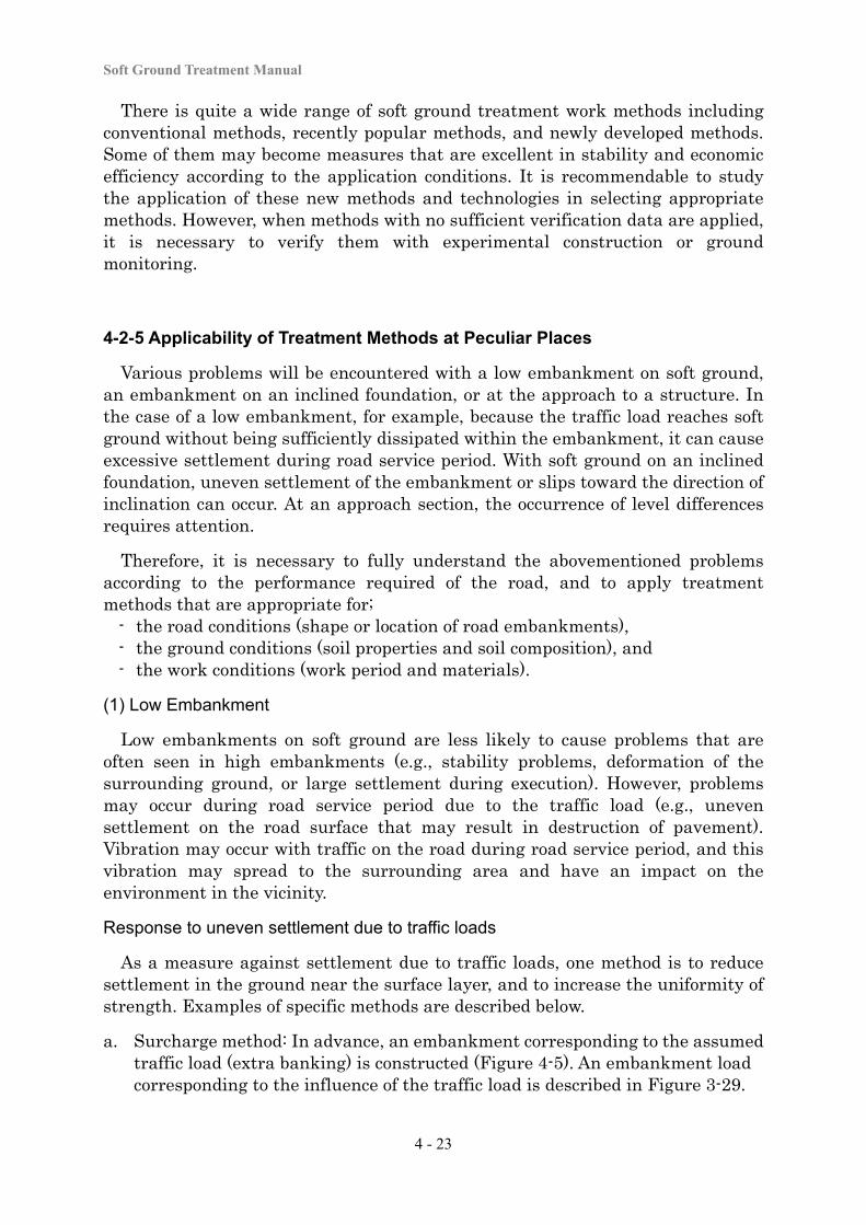
a. Surcharge method: In advance, an embankment corresponding to the assumed traffic load (extra banking) is constructed (Figure 4-5). An embankment load corresponding to the influence of the traffic load is described in Figure 3-29.
Chapter 4 Soft Ground Treatment Works
4 - 24
b. Shallow soil stabilization method: Cement- or lime-based additives are mixed with the subsurface soil of a weak layer to reinforce the ground strength.
c. Replacement method: The soil of the surface layer, which receives the largest portion of the traffic load, is replaced with good quality soil (see Figure 4-6).
Figure 4-5 Surcharge method Figure 4-6 Replacement method
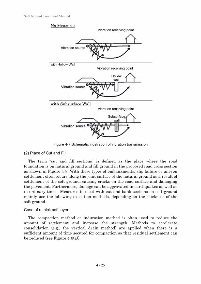
Reduction of traffic vibration
Measures to reduce traffic vibration are broadly divided into measures - for vibration sources (road structure), - for the spreading route (vibration isolation walls), and - for vibration receivers (structures that receive vibration).
Since traffic vibration often becomes obvious after a road opens to services, it is difficult to make a large change of the road structure. In general, measures for vibration spreading routes (e.g., pavement repair to reduce unevenness or constructing vibration isolation walls in the ground) are often studied. Measures for vibration spreading routes are methods to isolate or reduce vibration that spreads in the ground. Examples of specific methods include constructing empty trenches or underground walls along the vibration spreading route, as shown in Figure 4-7. An empty trench is constructed in the ground between the vibration source and the vibration receiver to mitigate vibration that spreads through the ground. It is generally difficult to maintain these as permanent facilities. Underground walls are made using two types of materials, rigid material (e.g., steel sheet piles or soil cement) and lightweight and less rigid material (e.g., Styrofoam). However, at present, there are few traffic vibration measures that are anticipated to be reliably effective. This is a field in which it is hoped that better methods will be developed in the future.
Soft Ground Treatment Manual
4 - 25
No Measures Vibration receiving point
with Hollow Wall
Vibration receiving point
with Subsurface Wall
Vibration receiving point
Figure 4-7 Schematic illustration of vibration transmission
(2) Place of Cut and Fill
The term “cut and fill sections” is defined as the place where the road foundation is on natural ground and fill ground in the proposed road cross section as shown in Figure 4-8. With these types of embankments, slip failure or uneven settlement often occurs along the joint surface of the natural ground as a result of settlement of the soft ground, causing cracks on the road surface and damaging the pavement. Furthermore, damage can be aggravated in earthquakes as well as in ordinary times. Measures to meet with cut and bank sections on soft ground mainly use the following execution methods, depending on the thickness of the soft ground.
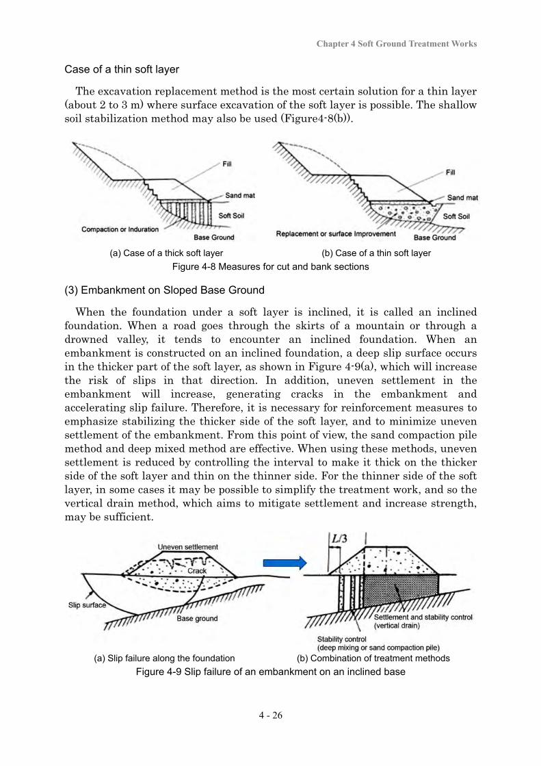
Case of a thick soft layer
The compaction method or induration method is often used to reduce the amount of settlement and increase the strength. Methods to accelerate consolidation (e.g., the vertical drain method) are applied when there is a sufficient amount of time secured for compaction so that residual settlement can be reduced (see Figure 4-8(a)).
Chapter 4 Soft Ground Treatment Works
4 - 26
Case of a thin soft layer
The excavation replacement method is the most certain solution for a thin layer (about 2 to 3 m) where surface excavation of the soft layer is possible. The shallow soil stabilization method may also be used (Figure4-8(b)).
(a) Case of a thick soft layer (b) Case of a thin soft layer
Figure 4-8 Measures for cut and bank sections
(3) Embankment on Sloped Base Ground
When the foundation under a soft layer is inclined, it is called an inclined foundation. When a road goes through the skirts of a mountain or through a drowned valley, it tends to encounter an inclined foundation. When an embankment is constructed on an inclined foundation, a deep slip surface occurs in the thicker part of the soft layer, as shown in Figure 4-9(a), which will increase the risk of slips in that direction. In addition, uneven settlement in the embankment will increase, generating cracks in the embankment and accelerating slip failure. Therefore, it is necessary for reinforcement measures to emphasize stabilizing the thicker side of the soft layer, and to minimize uneven settlement of the embankment. From this point of view, the sand compaction pile method and deep mixed method are effective. When using these methods, uneven settlement is reduced by controlling the interval to make it thick on the thicker side of the soft layer and thin on the thinner side. For the thinner side of the soft layer, in some cases it may be possible to simplify the treatment work, and so the vertical drain method, which aims to mitigate settlement and increase strength, may be sufficient.
(a) Slip failure along the foundation (b) Combination of treatment methods
Figure 4-9 Slip failure of an embankment on an inclined base
Soft Ground Treatment Manual
4 - 27
When different methods are jointly conducted, cracking or uneven settlement can occur on the road surface. Therefore, it is necessary to pay attention to the places where different methods connect.
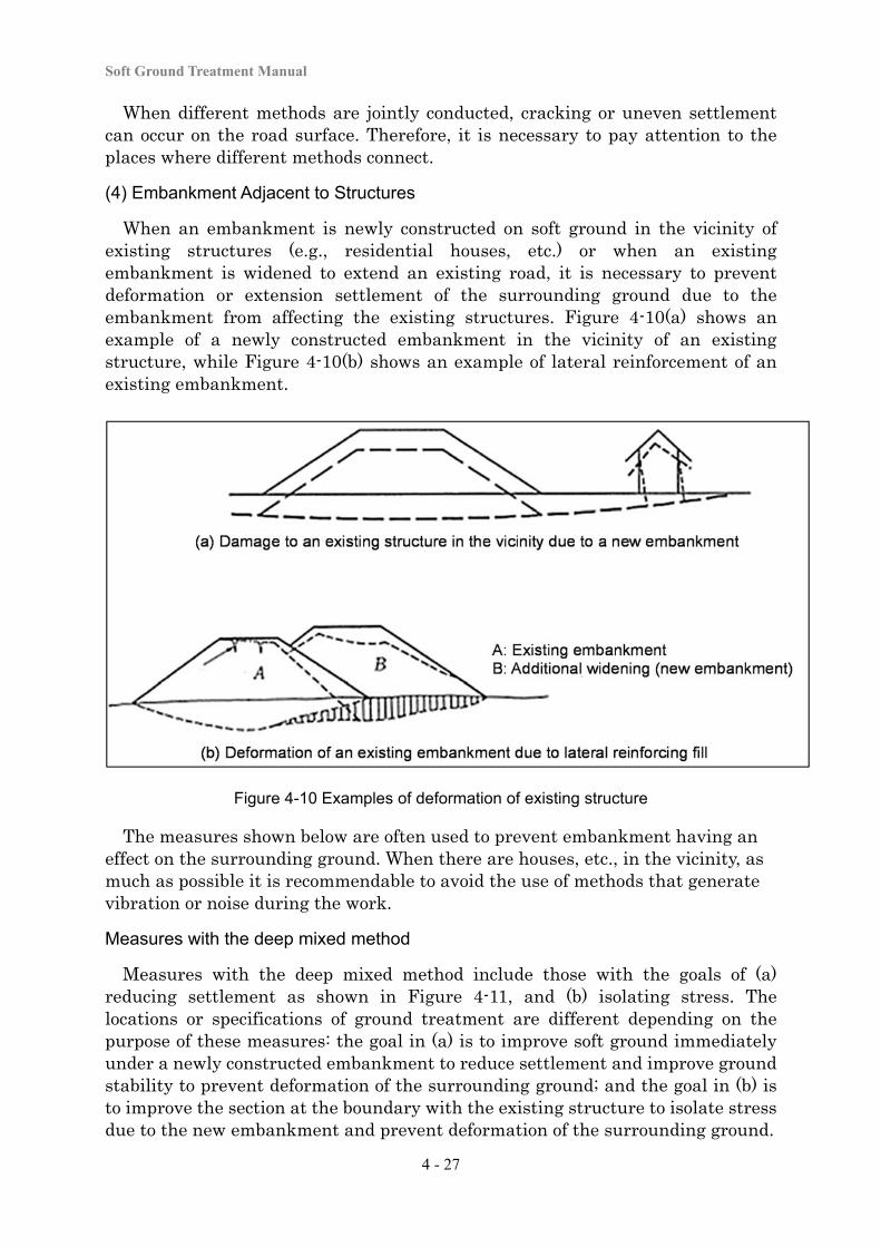
(4) Embankment Adjacent to Structures
When an embankment is newly constructed on soft ground in the vicinity of existing structures (e.g., residential houses, etc.) or when an existing embankment is widened to extend an existing road, it is necessary to prevent deformation or extension settlement of the surrounding ground due to the embankment from affecting the existing structures. Figure 4-10(a) shows an example of a newly constructed embankment in the vicinity of an existing structure, while Figure 4-10(b) shows an example of lateral reinforcement of an existing embankment.
Figure 4-10 Examples of deformation of existing structure
The measures shown below are often used to prevent embankment having an effect on the surrounding ground. When there are houses, etc., in the vicinity, as much as possible it is recommendable to avoid the use of methods that generate vibration or noise during the work.
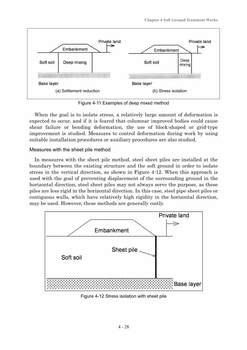
Measures with the deep mixed method
Measures with the deep mixed method include those with the goals of (a) reducing settlement as shown in Figure 4-11, and (b) isolating stress. The locations or specifications of ground treatment are different depending on the purpose of these measures: the goal in (a) is to improve soft ground immediately under a newly constructed embankment to reduce settlement and improve ground stability to prevent deformation of the surrounding ground; and the goal in (b) is to improve the section at the boundary with the existing structure to isolate stress due to the new embankment and prevent deformation of the surrounding ground.
Chapter 4 Soft Ground Treatment Works
4 - 28
(a) Settlement reduction (b) Stress isolation
Figure 4-11 Examples of deep mixed method
When the goal is to isolate stress, a relatively large amount of deformation is expected to occur, and if it is feared that columnar improved bodies could cause shear failure or bending deformation, the use of block-shaped or grid-type improvement is studied. Measures to control deformation during work by using suitable installation procedures or auxiliary procedures are also studied.
Measures with the sheet pile method
In measures with the sheet pile method, steel sheet piles are installed at the boundary between the existing structure and the soft ground in order to isolate stress in the vertical direction, as shown in Figure 4-12. When this approach is used with the goal of preventing displacement of the surrounding ground in the horizontal direction, steel sheet piles may not always serve the purpose, as these piles are less rigid in the horizontal direction. In this case, steel pipe sheet piles or contiguous walls, which have relatively high rigidity in the horizontal direction, may be used. However, these methods are generally costly.
Figure 4-12 Stress isolation with sheet pile
Soft Ground Treatment Manual
4 - 29
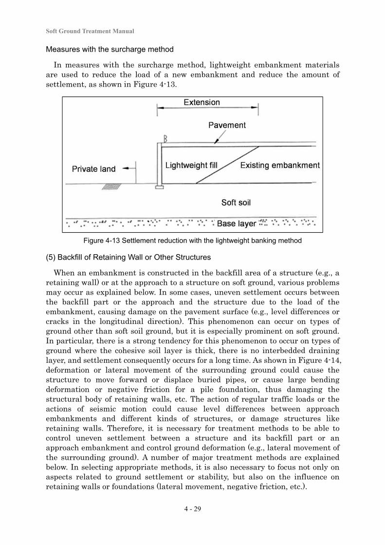
Measures with the surcharge method
In measures with the surcharge method, lightweight embankment materials are used to reduce the load of a new embankment and reduce the amount of settlement, as shown in Figure 4-13.
Figure 4-13 Settlement reduction with the lightweight banking method
(5) Backfill of Retaining Wall or Other Structures
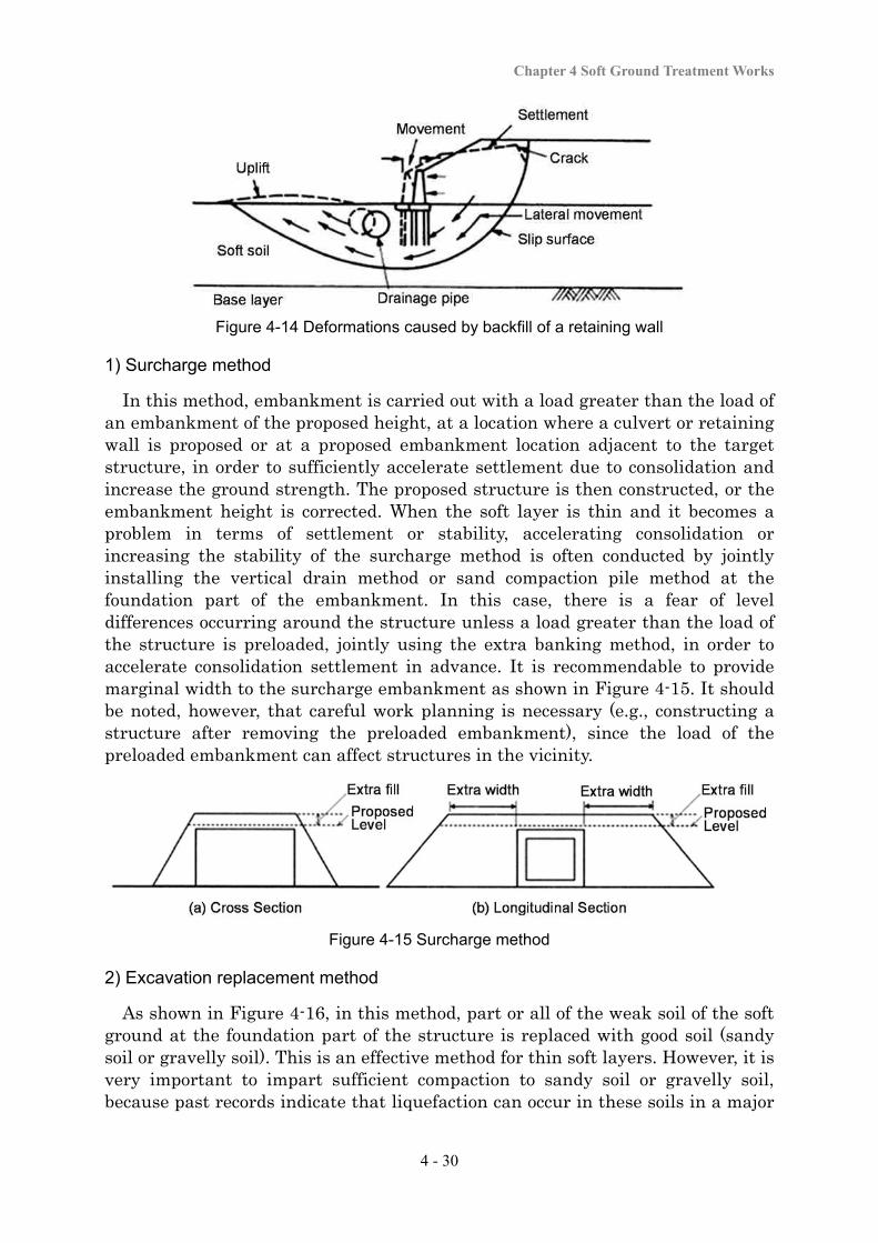
When an embankment is constructed in the backfill area of a structure (e.g., a retaining wall) or at the approach to a structure on soft ground, various problems may occur as explained below. In some cases, uneven settlement occurs between the backfill part or the approach and the structure due to the load of the embankment, causing damage on the pavement surface (e.g., level differences or cracks in the longitudinal direction). This phenomenon can occur on types of ground other than soft soil ground, but it is especially prominent on soft ground. In particular, there is a strong tendency for this phenomenon to occur on types of ground where the cohesive soil layer is thick, there is no interbedded draining layer, and settlement consequently occurs for a long time. As shown in Figure 4-14, deformation or lateral movement of the surrounding ground could cause the structure to move forward or displace buried pipes, or cause large bending deformation or negative friction for a pile foundation, thus damaging the structural body of retaining walls, etc. The action of regular traffic loads or the actions of seismic motion could cause level differences between approach embankments and different kinds of structures, or damage structures like retaining walls. Therefore, it is necessary for treatment methods to be able to control uneven settlement between a structure and its backfill part or an approach embankment and control ground deformation (e.g., lateral movement of the surrounding ground). A number of major treatment methods are explained below. In selecting appropriate methods, it is also necessary to focus not only on aspects related to ground settlement or stability, but also on the influence on retaining walls or foundations (lateral movement, negative friction, etc.).
Chapter 4 Soft Ground Treatment Works
4 - 30
Figure 4-14 Deformations caused by backfill of a retaining wall
1) Surcharge method
In this method, embankment is carried out with a load greater than the load of an embankment of the proposed height, at a location where a culvert or retaining wall is proposed or at a proposed embankment location adjacent to the target structure, in order to sufficiently accelerate settlement due to consolidation and increase the ground strength. The proposed structure is then constructed, or the embankment height is corrected. When the soft layer is thin and it becomes a problem in terms of settlement or stability, accelerating consolidation or increasing the stability of the surcharge method is often conducted by jointly installing the vertical drain method or sand compaction pile method at the foundation part of the embankment. In this case, there is a fear of level differences occurring around the structure unless a load greater than the load of the structure is preloaded, jointly using the extra banking method, in order to accelerate consolidation settlement in advance. It is recommendable to provide marginal width to the surcharge embankment as shown in Figure 4-15. It should be noted, however, that careful work planning is necessary (e.g., constructing a structure after removing the preloaded embankment), since the load of the preloaded embankment can affect structures in the vicinity.
Figure 4-15 Surcharge method
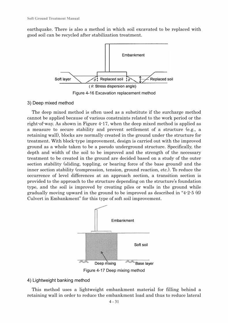
2) Excavation replacement method
As shown in Figure 4-16, in this method, part or all of the weak soil of the soft ground at the foundation part of the structure is replaced with good soil (sandy soil or gravelly soil). This is an effective method for thin soft layers. However, it is very important to impart sufficient compaction to sandy soil or gravelly soil, because past records indicate that liquefaction can occur in these soils in a major
Soft Ground Treatment Manual
4 - 31
earthquake. There is also a method in which soil excavated to be replaced with good soil can be recycled after stabilization treatment.
Figure 4-16 Excavation replacement method
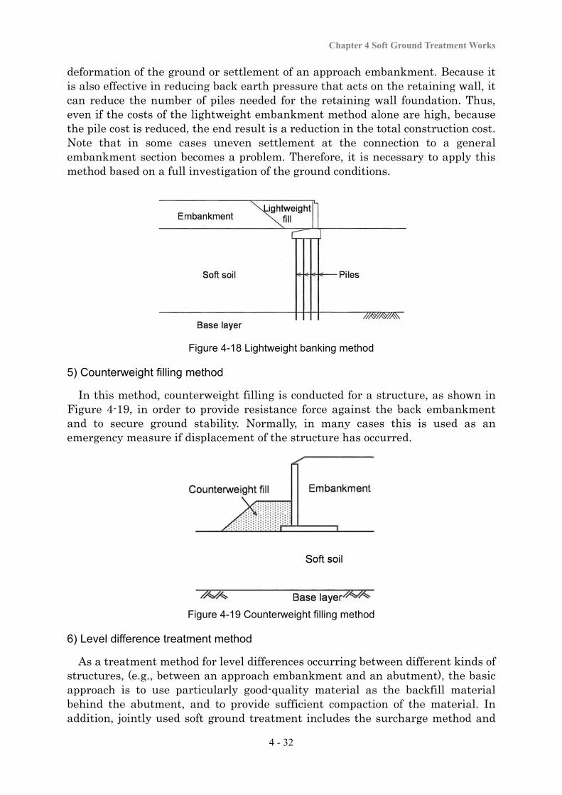
3) Deep mixed method
The deep mixed method is often used as a substitute if the surcharge method cannot be applied because of various constraints related to the work period or the right-of-way. As shown in Figure 4-17, when the deep mixed method is applied as a measure to secure stability and prevent settlement of a structure (e.g., a retaining wall), blocks are normally created in the ground under the structure for treatment. With block-type improvement, design is carried out with the improved ground as a whole taken to be a pseudo underground structure. Specifically, the depth and width of the soil to be improved and the strength of the necessary treatment to be created in the ground are decided based on a study of the outer section stability (sliding, toppling, or bearing force of the base ground) and the inner section stability (compression, tension, ground reaction, etc.). To reduce the occurrence of level differences at an approach section, a transition section is provided to the approach to the structure depending on the structure’s foundation type, and the soil is improved by creating piles or walls in the ground while gradually moving upward in the ground to be improved as described in “4-2-5 (6) Culvert in Embankment” for this type of soft soil improvement.
Figure 4-17 Deep mixing method
4) Lightweight banking method
This method uses a lightweight embankment material for filling behind a retaining wall in order to reduce the embankment load and thus to reduce lateral
Chapter 4 Soft Ground Treatment Works
4 - 32
deformation of the ground or settlement of an approach embankment. Because it is also effective in reducing back earth pressure that acts on the retaining wall, it can reduce the number of piles needed for the retaining wall foundation. Thus, even if the costs of the lightweight embankment method alone are high, because the pile cost is reduced, the end result is a reduction in the total construction cost. Note that in some cases uneven settlement at the connection to a general embankment section becomes a problem. Therefore, it is necessary to apply this method based on a full investigation of the ground conditions.
Figure 4-18 Lightweight banking method
5) Counterweight filling method
In this method, counterweight filling is conducted for a structure, as shown in Figure 4-19, in order to provide resistance force against the back embankment and to secure ground stability. Normally, in many cases this is used as an emergency measure if displacement of the structure has occurred.
Figure 4-19 Counterweight filling method
6) Level difference treatment method
As a treatment method for level differences occurring between different kinds of structures, (e.g., between an approach embankment and an abutment), the basic approach is to use particularly good-quality material as the backfill material behind the abutment, and to provide sufficient compaction of the material. In addition, jointly used soft ground treatment includes the surcharge method and
Soft Ground Treatment Manual
4 - 33
soft soil improvement as well as approach cushioning, backfilling, and pavement patching and overlaying.
Approach slabs
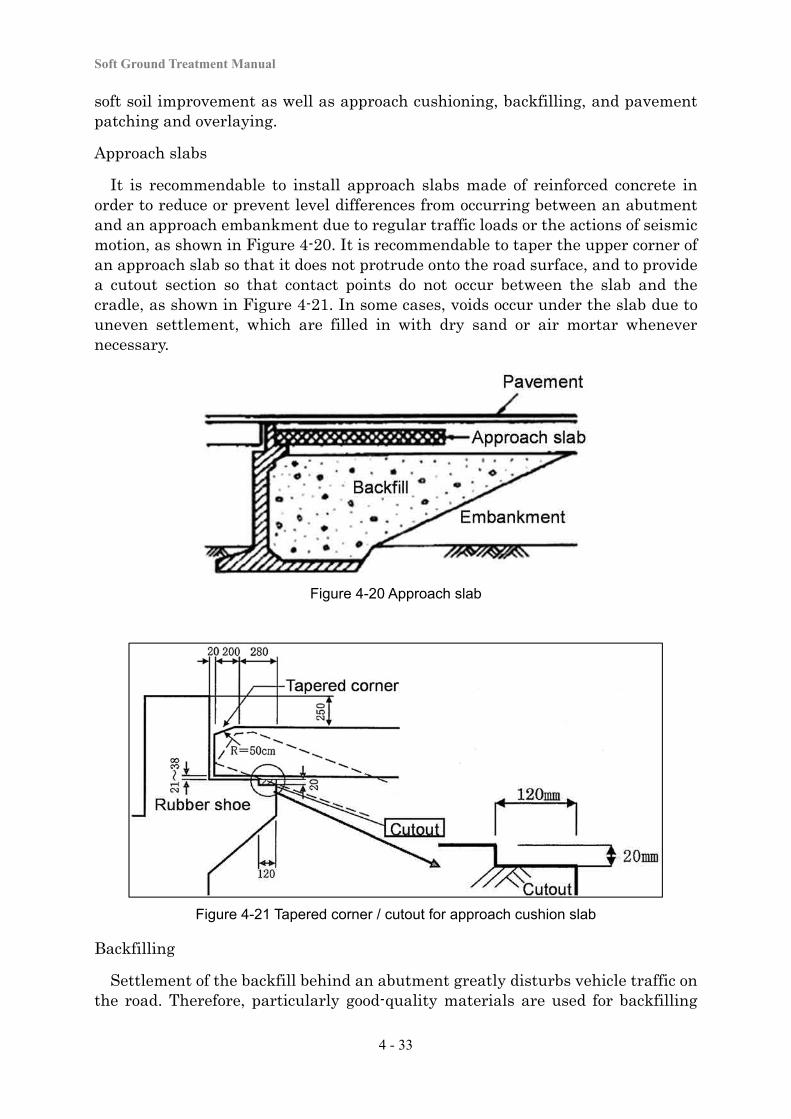
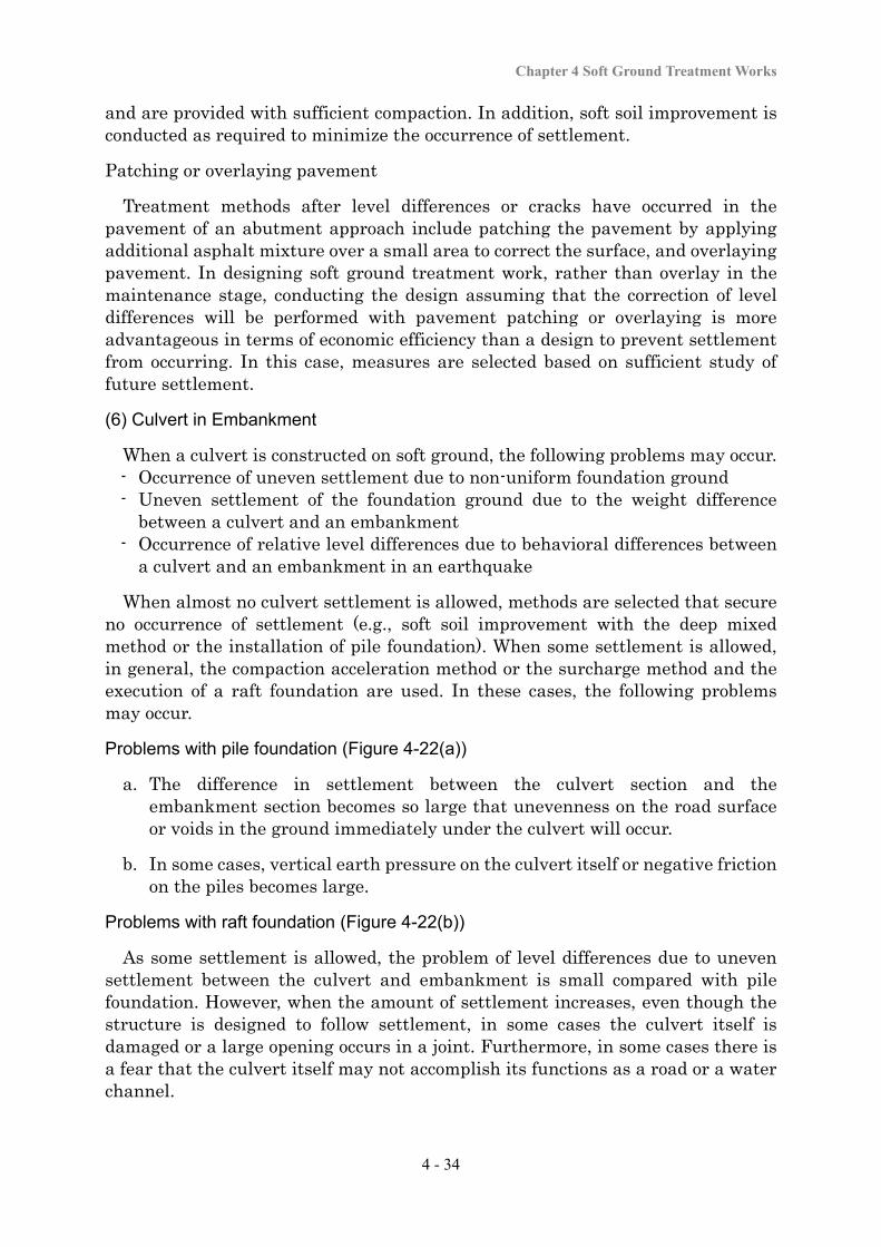
It is recommendable to install approach slabs made of reinforced concrete in order to reduce or prevent level differences from occurring between an abutment and an approach embankment due to regular traffic loads or the actions of seismic motion, as shown in Figure 4-20. It is recommendable to taper the upper corner of an approach slab so that it does not protrude onto the road surface, and to provide a cutout section so that contact points do not occur between the slab and the cradle, as shown in Figure 4-21. In some cases, voids occur under the slab due to uneven settlement, which are filled in with dry sand or air mortar whenever necessary.
Figure 4-20 Approach slab
Figure 4-21 Tapered corner / cutout for approach cushion slab
Backfilling
Settlement of the backfill behind an abutment greatly disturbs vehicle traffic on the road. Therefore, particularly good-quality materials are used for backfilling
Chapter 4 Soft Ground Treatment Works
4 - 34
and are provided with sufficient compaction. In addition, soft soil improvement is conducted as required to minimize the occurrence of settlement.
Patching or overlaying pavement
Treatment methods after level differences or cracks have occurred in the pavement of an abutment approach include patching the pavement by applying additional asphalt mixture over a small area to correct the surface, and overlaying pavement. In designing soft ground treatment work, rather than overlay in the maintenance stage, conducting the design assuming that the correction of level differences will be performed with pavement patching or overlaying is more advantageous in terms of economic efficiency than a design to prevent settlement from occurring. In this case, measures are selected based on sufficient study of future settlement.
(6) Culvert in Embankment
When a culvert is constructed on soft ground, the following problems may occur. - Occurrence of uneven settlement due to non-uniform foundation ground - Uneven settlement of the foundation ground due to the weight difference
between a culvert and an embankment - Occurrence of relative level differences due to behavioral differences between
a culvert and an embankment in an earthquake
When almost no culvert settlement is allowed, methods are selected that secure no occurrence of settlement (e.g., soft soil improvement with the deep mixed method or the installation of pile foundation). When some settlement is allowed, in general, the compaction acceleration method or the surcharge method and the execution of a raft foundation are used. In these cases, the following problems may occur.
Problems with pile foundation (Figure 4-22(a))
a. The difference in settlement between the culvert section and the embankment section becomes so large that unevenness on the road surface or voids in the ground immediately under the culvert will occur.
b. In some cases, vertical earth pressure on the culvert itself or negative friction on the piles becomes large.
Problems with raft foundation (Figure 4-22(b))
As some settlement is allowed, the problem of level differences due to uneven settlement between the culvert and embankment is small compared with pile foundation. However, when the amount of settlement increases, even though the structure is designed to follow settlement, in some cases the culvert itself is damaged or a large opening occurs in a joint. Furthermore, in some cases there is a fear that the culvert itself may not accomplish its functions as a road or a water channel.

Soft Ground Treatment Manual
4 - 35
(a) with pile foundation (b) with raft foundation Figure 4-22 Culvert and displacement of the surrounding area
3) Other problems
When a culvert is constructed on ground composed of inhomogeneous soils, or when a culvert having a large cross-section and a large bevel is constructed on soft ground, uneven settlement or movement due to eccentric earth pressure can occur, as shown in Figure 4-23, and in some cases this damages the culvert. In the filling works of a culvert, if there is a difference in the height of both sides of the embankment with a raft foundation, the culvert may move, or with a pile foundation, eccentric loads may affect the piles. Therefore, in the work, it is necessary to minimize lateral movement and residual settlement. It is also necessary to pay attention to procedures that secure the filling works without causing eccentric loads (e.g., by building up the backfill material to the same height on both sides). Specific solutions to the above problems include preloading, excavation replacement, the deep mixed method, or lightweight embankment.
(a) Non-uniform ground (b) Large culvert with large bevel Figure 4-23 Culvert subject to uneven settlement
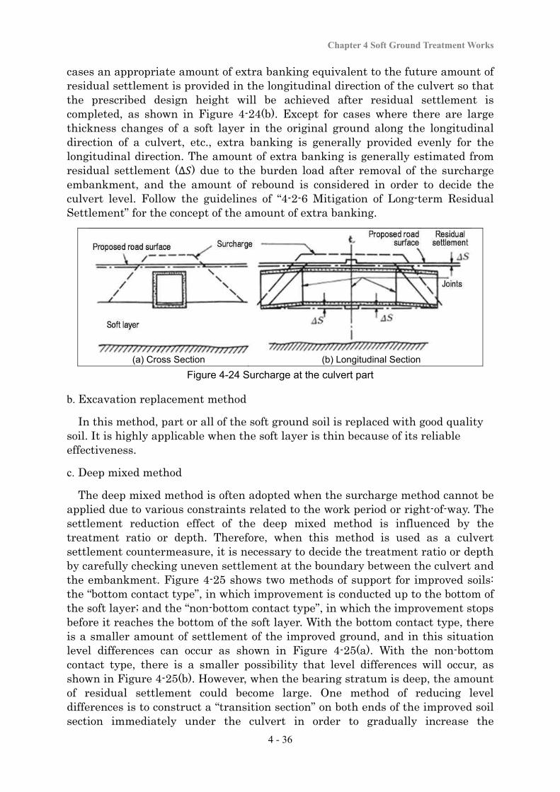
a. Surcharge method
As shown in Figure 4-24(a), in the surcharge method, an embankment load is applied in advance to the ground to accelerate ground settlement, the ground is left until residual settlement reaches the target amount, the surcharge embankment is removed, and culverts are constructed. This is the method used in the greatest number of cases. If large residual settlement is predicted, in some
Chapter 4 Soft Ground Treatment Works
4 - 36
cases an appropriate amount of extra banking equivalent to the future amount of residual settlement is provided in the longitudinal direction of the culvert so that the prescribed design height will be achieved after residual settlement is completed, as shown in Figure 4-24(b). Except for cases where there are large thickness changes of a soft layer in the original ground along the longitudinal direction of a culvert, etc., extra banking is generally provided evenly for the longitudinal direction. The amount of extra banking is generally estimated from residual settlement (∆ ) due to the burden load after removal of the surcharge embankment, and the amount of rebound is considered in order to decide the culvert level. Follow the guidelines of “4-2-6 Mitigation of Long-term Residual Settlement” for the concept of the amount of extra banking.
(a) Cross Section (b) Longitudinal Section
Figure 4-24 Surcharge at the culvert part
b. Excavation replacement method
In this method, part or all of the soft ground soil is replaced with good quality soil. It is highly applicable when the soft layer is thin because of its reliable effectiveness.
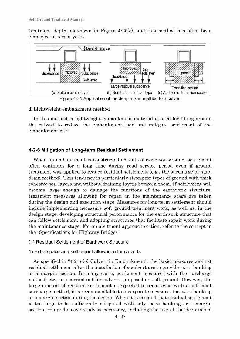
c. Deep mixed method
The deep mixed method is often adopted when the surcharge method cannot be applied due to various constraints related to the work period or right-of-way. The settlement reduction effect of the deep mixed method is influenced by the treatment ratio or depth. Therefore, when this method is used as a culvert settlement countermeasure, it is necessary to decide the treatment ratio or depth by carefully checking uneven settlement at the boundary between the culvert and the embankment. Figure 4-25 shows two methods of support for improved soils: the “bottom contact type”, in which improvement is conducted up to the bottom of the soft layer; and the “non-bottom contact type”, in which the improvement stops before it reaches the bottom of the soft layer. With the bottom contact type, there is a smaller amount of settlement of the improved ground, and in this situation level differences can occur as shown in Figure 4-25(a). With the non-bottom contact type, there is a smaller possibility that level differences will occur, as shown in Figure 4-25(b). However, when the bearing stratum is deep, the amount of residual settlement could become large. One method of reducing level differences is to construct a “transition section” on both ends of the improved soil section immediately under the culvert in order to gradually increase the
Soft Ground Treatment Manual
4 - 37
treatment depth, as shown in Figure 4-25(c), and this method has often been employed in recent years.
(a) Bottom contact type (b) Non-bottom contact type (c) Addition of transition section
Figure 4-25 Application of the deep mixed method to a culvert d. Lightweight embankment method
In this method, a lightweight embankment material is used for filling around the culvert to reduce the embankment load and mitigate settlement of the embankment part.
4-2-6 Mitigation of Long-term Residual Settlement
When an embankment is constructed on soft cohesive soil ground, settlement often continues for a long time during road service period even if ground treatment was applied to reduce residual settlement (e.g., the surcharge or sand drain method). This tendency is particularly strong for types of ground with thick cohesive soil layers and without draining layers between them. If settlement will become large enough to damage the functions of the earthwork structure, treatment measures allowing for repair in the maintenance stage are taken during the design and execution stage. Measures for long-term settlement should include implementing necessary soft ground treatment work, as well as, in the design stage, developing structural performance for the earthwork structure that can follow settlement, and adopting structures that facilitate repair work during the maintenance stage. For an abutment approach section, refer to the concept in the “Specifications for Highway Bridges”.
(1) Residual Settlement of Earthwork Structure
1) Extra space and settlement allowance for culverts
As specified in “4-2-5 (6) Culvert in Embankment”, the basic measures against residual settlement after the installation of a culvert are to provide extra banking or a margin section. In many cases, settlement measures with the surcharge method, etc., are carried out for culverts proposed on soft ground. However, if a large amount of residual settlement is expected to occur even with a sufficient surcharge method, it is recommendable to incorporate measures for extra banking or a margin section during the design. When it is decided that residual settlement is too large to be sufficiently mitigated with only extra banking or a margin section, comprehensive study is necessary, including the use of the deep mixed

Chapter 4 Soft Ground Treatment Works
4 - 38
method and other methods. During the surcharge method, residual settlement is estimated based on the settlement observation results and differences from the forecast at the time of the design are checked. If residual settlement greatly differs from what was forecast during the design, it is necessary to reexamine the design of the culvert.
Culverts for roads
A basic measure is the provision of extra banking. However, the maximum amount of extra banking applicable to a box culvert is 30 cm due to the structural characteristics of the culvert joint. Therefore, when providing extra banking greater than this amount, it is necessary to separately study the joint structure. As shown in Figure 4-26, if the amount of extra banking becomes great, it is necessary to reconsider the vertical grade of the intersecting road. When measures with extra banking alone will be difficult, it is recommendable to add measures with a margin section.
Figure 4-26 Extra banking of culvert
For culverts, the surcharge method is a basic measure for settlement. However, in many cases the shape of extra banking with long-term continuation of residual settlement is uniform in the longitudinal direction of the culvert as shown in Figure 4-27(a).
(a) With Surcharge method
Sr: Settlement allowance
(b) Without surcharge method
D : Thickness of overburden soil : Extra banking at the culvert center : Extra banking at the culvert edge
r : Settlement ratio =
(c) Settlement ratio
Figure 4-27 Settlement Allowance of Culvert
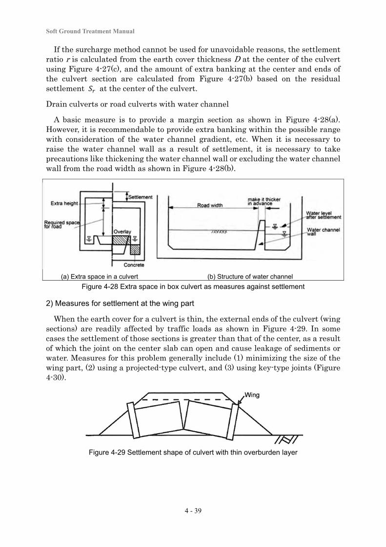
Soft Ground Treatment Manual
4 - 39
If the surcharge method cannot be used for unavoidable reasons, the settlement ratio r is calculated from the earth cover thickness D at the center of the culvert using Figure 4-27(c), and the amount of extra banking at the center and ends of the culvert section are calculated from Figure 4-27(b) based on the residual settlement at the center of the culvert.
Drain culverts or road culverts with water channel
A basic measure is to provide a margin section as shown in Figure 4-28(a). However, it is recommendable to provide extra banking within the possible range with consideration of the water channel gradient, etc. When it is necessary to raise the water channel wall as a result of settlement, it is necessary to take precautions like thickening the water channel wall or excluding the water channel wall from the road width as shown in Figure 4-28(b).
(a) Extra space in a culvert (b) Structure of water channel
Figure 4-28 Extra space in box culvert as measures against settlement
2) Measures for settlement at the wing part
When the earth cover for a culvert is thin, the external ends of the culvert (wing sections) are readily affected by traffic loads as shown in Figure 4-29. In some cases the settlement of those sections is greater than that of the center, as a result of which the joint on the center slab can open and cause leakage of sediments or water. Measures for this problem generally include (1) minimizing the size of the wing part, (2) using a projected-type culvert, and (3) using key-type joints (Figure 4-30).
Figure 4-29 Settlement shape of culvert with thin overburden layer
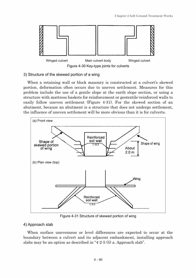
Chapter 4 Soft Ground Treatment Works
4 - 40
Winged culvert Main culvert body Winged culvert
Figure 4-30 Key-type joints for culverts
3) Structure of the skewed portion of a wing
When a retaining wall or block masonry is constructed at a culvert’s skewed portion, deformation often occurs due to uneven settlement. Measures for this problem include the use of a gentle slope at the earth slope section, or using a structure with mattress baskets for reinforcement or geotextile-reinforced walls to easily follow uneven settlement (Figure 4-31). For the skewed section of an abutment, because an abutment is a structure that does not undergo settlement, the influence of uneven settlement will be more obvious than it is for culverts.
(a) Front view
(b) Plan view (top)
Figure 4-31 Structure of skewed portion of wing
4) Approach slab
When surface unevenness or level differences are expected to occur at the boundary between a culvert and its adjacent embankment, installing approach slabs may be an option as described in “4-2-5 (5) a. Approach slab”.
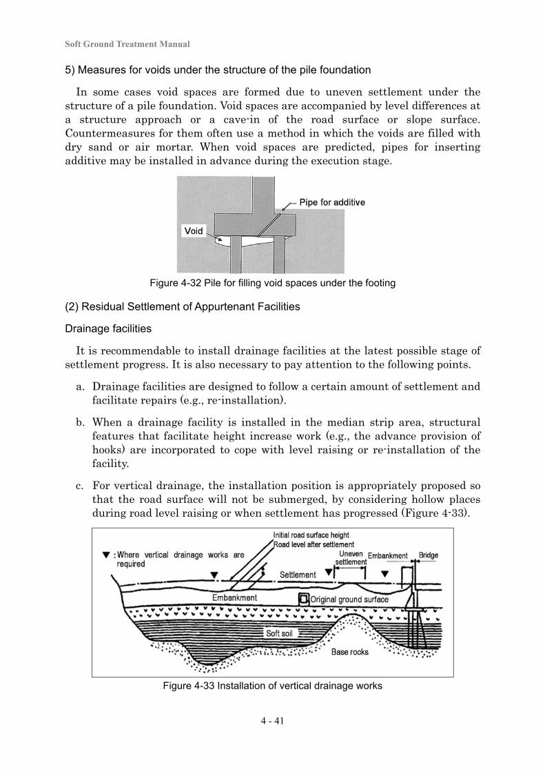
Soft Ground Treatment Manual
4 - 41
5) Measures for voids under the structure of the pile foundation
In some cases void spaces are formed due to uneven settlement under the structure of a pile foundation. Void spaces are accompanied by level differences at a structure approach or a cave-in of the road surface or slope surface. Countermeasures for them often use a method in which the voids are filled with dry sand or air mortar. When void spaces are predicted, pipes for inserting additive may be installed in advance during the execution stage.
Figure 4-32 Pile for filling void spaces under the footing
(2) Residual Settlement of Appurtenant Facilities
Drainage facilities
It is recommendable to install drainage facilities at the latest possible stage of settlement progress. It is also necessary to pay attention to the following points.
a. Drainage facilities are designed to follow a certain amount of settlement and facilitate repairs (e.g., re-installation).
b. When a drainage facility is installed in the median strip area, structural features that facilitate height increase work (e.g., the advance provision of hooks) are incorporated to cope with level raising or re-installation of the facility.
c. For vertical drainage, the installation position is appropriately proposed so that the road surface will not be submerged, by considering hollow places during road level raising or when settlement has progressed (Figure 4-33).
Figure 4-33 Installation of vertical drainage works
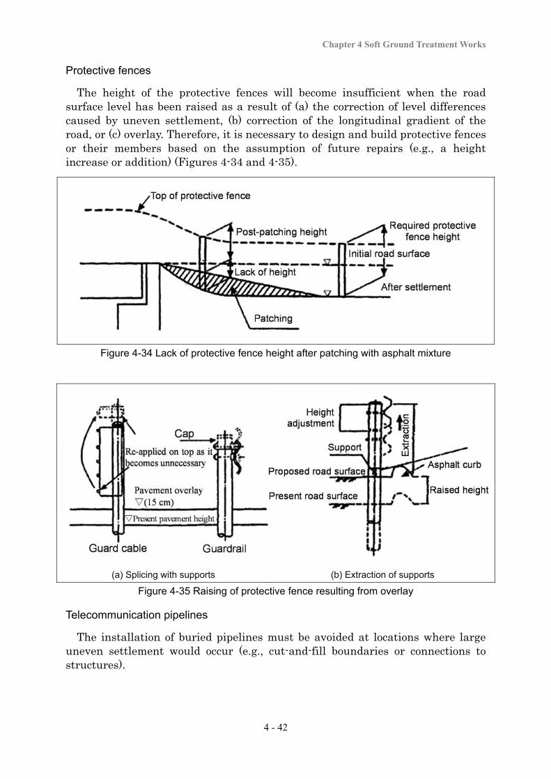
Chapter 4 Soft Ground Treatment Works
4 - 42
Protective fences
The height of the protective fences will become insufficient when the road surface level has been raised as a result of (a) the correction of level differences caused by uneven settlement, (b) correction of the longitudinal gradient of the road, or (c) overlay. Therefore, it is necessary to design and build protective fences or their members based on the assumption of future repairs (e.g., a height increase or addition) (Figures 4-34 and 4-35).
Figure 4-34 Lack of protective fence height after patching with asphalt mixture
(a) Splicing with supports (b) Extraction of supports Figure 4-35 Raising of protective fence resulting from overlay
Telecommunication pipelines
The installation of buried pipelines must be avoided at locations where large uneven settlement would occur (e.g., cut-and-fill boundaries or connections to structures).
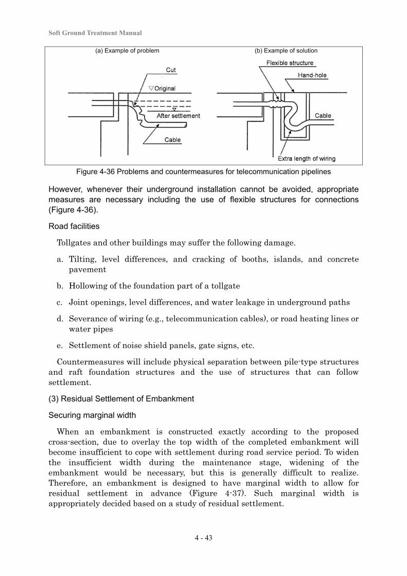
Soft Ground Treatment Manual
4 - 43
(a) Example of problem (b) Example of solution
Figure 4-36 Problems and countermeasures for telecommunication pipelines
However, whenever their underground installation cannot be avoided, appropriate measures are necessary including the use of flexible structures for connections (Figure 4-36).
Road facilities
Tollgates and other buildings may suffer the following damage.
a. Tilting, level differences, and cracking of booths, islands, and concrete pavement
b. Hollowing of the foundation part of a tollgate
c. Joint openings, level differences, and water leakage in underground paths
d. Severance of wiring (e.g., telecommunication cables), or road heating lines or water pipes
e. Settlement of noise shield panels, gate signs, etc.
Countermeasures will include physical separation between pile-type structures and raft foundation structures and the use of structures that can follow settlement.
(3) Residual Settlement of Embankment
Securing marginal width
When an embankment is constructed exactly according to the proposed cross-section, due to overlay the top width of the completed embankment will become insufficient to cope with settlement during road service period. To widen the insufficient width during the maintenance stage, widening of the embankment would be necessary, but this is generally difficult to realize. Therefore, an embankment is designed to have marginal width to allow for residual settlement in advance (Figure 4-37). Such marginal width is appropriately decided based on a study of residual settlement.
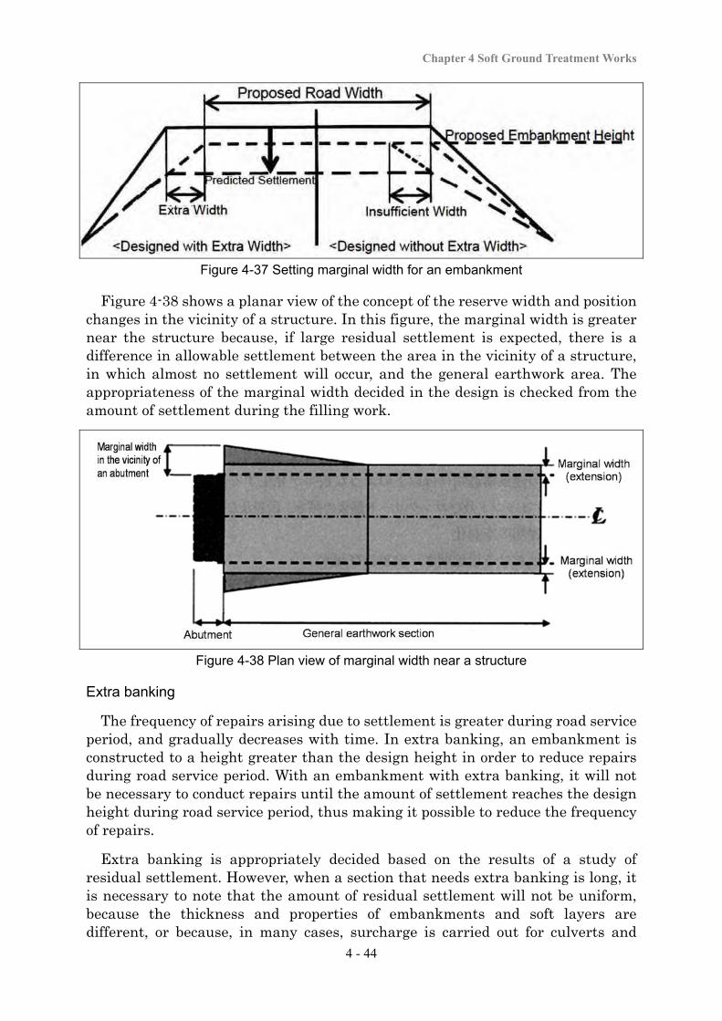
Chapter 4 Soft Ground Treatment Works
4 - 44
Figure 4-37 Setting marginal width for an embankment
Figure 4-38 shows a planar view of the concept of the reserve width and position changes in the vicinity of a structure. In this figure, the marginal width is greater near the structure because, if large residual settlement is expected, there is a difference in allowable settlement between the area in the vicinity of a structure, in which almost no settlement will occur, and the general earthwork area. The appropriateness of the marginal width decided in the design is checked from the amount of settlement during the filling work.
Figure 4-38 Plan view of marginal width near a structure
Extra banking
The frequency of repairs arising due to settlement is greater during road service period, and gradually decreases with time. In extra banking, an embankment is constructed to a height greater than the design height in order to reduce repairs during road service period. With an embankment with extra banking, it will not be necessary to conduct repairs until the amount of settlement reaches the design height during road service period, thus making it possible to reduce the frequency of repairs.
Extra banking is appropriately decided based on the results of a study of residual settlement. However, when a section that needs extra banking is long, it is necessary to note that the amount of residual settlement will not be uniform, because the thickness and properties of embankments and soft layers are different, or because, in many cases, surcharge is carried out for culverts and
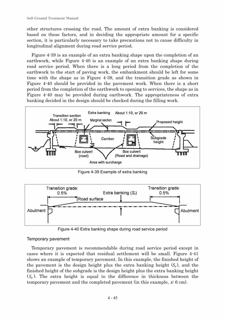
Soft Ground Treatment Manual
4 - 45
other structures crossing the road. The amount of extra banking is considered based on these factors, and in deciding the appropriate amount for a specific section, it is particularly necessary to take precautions not to cause difficulty in longitudinal alignment during road service period.
Figure 4-39 is an example of an extra banking shape upon the completion of an earthwork, while Figure 4-40 is an example of an extra banking shape during road service period. When there is a long period from the completion of the earthwork to the start of paving work, the embankment should be left for some time with the shape as in Figure 4-39, and the transition grade as shown in Figure 4-40 should be provided in the pavement work. When there is a short period from the completion of the earthwork to opening to services, the shape as in Figure 4-40 may be provided during earthwork. The appropriateness of extra banking decided in the design should be checked during the filling work.
Figure 4-39 Example of extra banking
Figure 4-40 Extra banking shape during road service period
Temporary pavement
Temporary pavement is recommendable during road service period except in cases where it is expected that residual settlement will be small. Figure 4-41 shows an example of temporary pavement. In this example, the finished height of the pavement is the design height plus the extra banking height ( ), and the finished height of the subgrade is the design height plus the extra banking height ( ). The extra height is equal to the difference in thickness between the temporary pavement and the completed pavement (in this example, x: 6 cm).
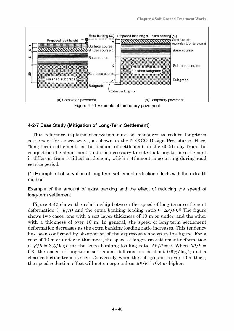
Chapter 4 Soft Ground Treatment Works
4 - 46
(a) Completed pavement (b) Temporary pavement Figure 4-41 Example of temporary pavement
4-2-7 Case Study (Mitigation of Long-Term Settlement)
This reference explains observation data on measures to reduce long-term settlement for expressways, as shown in the NEXCO Design Procedures. Here, “long-term settlement” is the amount of settlement on the 600th day from the completion of embankment, and it is necessary to note that long-term settlement is different from residual settlement, which settlement is occurring during road service period.
(1) Example of observation of long-term settlement reduction effects with the extra fill method
Example of the amount of extra banking and the effect of reducing the speed of long-term settlement
Figure 4-42 shows the relationship between the speed of long-term settlement deformation ( / ) and the extra banking loading ratio ( ∆ / ).3) The figure shows two cases: one with a soft layer thickness of 10 m or under, and the other with a thickness of over 10 m. In general, the speed of long-term settlement deformation decreases as the extra banking loading ratio increases. This tendency has been confirmed by observation of the expressway shown in the figure. For a case of 10 m or under in thickness, the speed of long-term settlement deformation is / ≒ 3%/ log for the extra banking loading ratio ∆ / 0. When ∆ /0.3, the speed of long-term settlement deformation is about 0.8%/ log , and a clear reduction trend is seen. Conversely, when the soft ground is over 10 m thick, the speed reduction effect will not emerge unless ∆ / is 0.4 or higher.
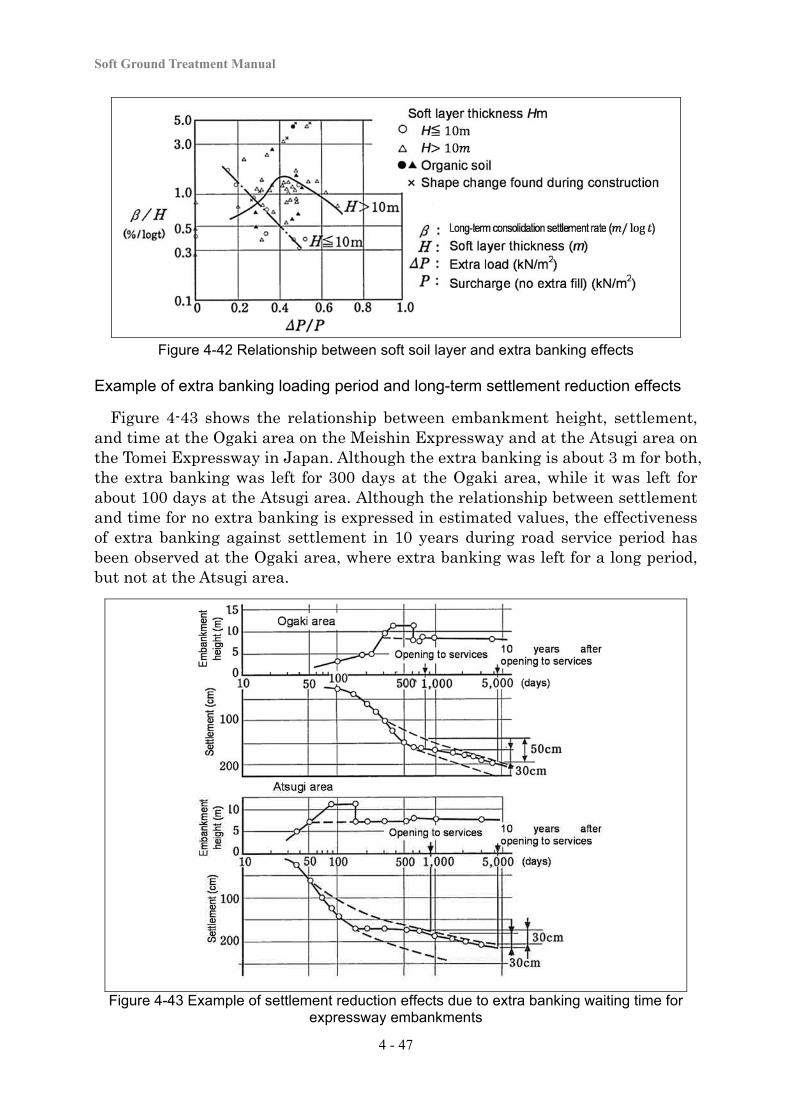
Soft Ground Treatment Manual
4 - 47
Figure 4-42 Relationship between soft soil layer and extra banking effects
Example of extra banking loading period and long-term settlement reduction effects
Figure 4-43 shows the relationship between embankment height, settlement, and time at the Ogaki area on the Meishin Expressway and at the Atsugi area on the Tomei Expressway in Japan. Although the extra banking is about 3 m for both, the extra banking was left for 300 days at the Ogaki area, while it was left for about 100 days at the Atsugi area. Although the relationship between settlement and time for no extra banking is expressed in estimated values, the effectiveness of extra banking against settlement in 10 years during road service period has been observed at the Ogaki area, where extra banking was left for a long period, but not at the Atsugi area.
Figure 4-43 Example of settlement reduction effects due to extra banking waiting time for expressway embankments
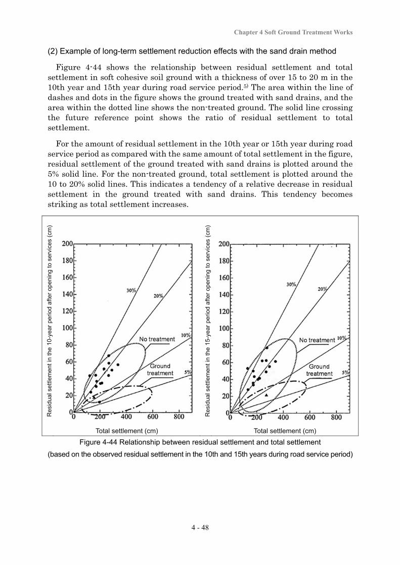
Chapter 4 Soft Ground Treatment Works
4 - 48
(2) Example of long-term settlement reduction effects with the sand drain method
Figure 4-44 shows the relationship between residual settlement and total settlement in soft cohesive soil ground with a thickness of over 15 to 20 m in the 10th year and 15th year during road service period.5) The area within the line of dashes and dots in the figure shows the ground treated with sand drains, and the area within the dotted line shows the non-treated ground. The solid line crossing the future reference point shows the ratio of residual settlement to total settlement.
For the amount of residual settlement in the 10th year or 15th year during road service period as compared with the same amount of total settlement in the figure, residual settlement of the ground treated with sand drains is plotted around the 5% solid line. For the non-treated ground, total settlement is plotted around the 10 to 20% solid lines. This indicates a tendency of a relative decrease in residual settlement in the ground treated with sand drains. This tendency becomes striking as total settlement increases.
Res
idua
l set
tlem
ent i
n th
e 1
0-ye
ar p
erio
d af
ter
ope
nin
g to
ser
vice
s (c
m)
Res
idua
l set
tlem
ent i
n th
e 1
5-ye
ar p
erio
d af
ter
ope
nin
g to
ser
vice
s (c
m)
Total settlement (cm) Total settlement (cm)
Figure 4-44 Relationship between residual settlement and total settlement
(based on the observed residual settlement in the 10th and 15th years during road service period)
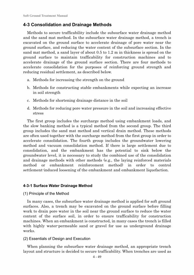
Soft Ground Treatment Manual
4 - 49
4-3 Consolidation and Drainage Methods
Methods to secure trafficability include the subsurface water drainage method and the sand mat method. In the subsurface water drainage method, a trench is excavated on the ground surface to accelerate drainage of pore water near the ground surface, and reducing the water content of the subsurface section. In the sand mat method, a sand layer of about 0.5 to 1.2 m in thickness is spread on the ground surface to maintain trafficability for construction machines and to accelerate drainage of the ground surface section. There are four methods to accelerate consolidation for the purposes of reinforcing ground strength and reducing residual settlement, as described below.
a. Methods for increasing the strength on the ground
b. Methods for constructing stable embankments while expecting an increase in soil strength
c. Methods for shortening drainage distance in the soil
d. Methods for reducing pore water pressure in the soil and increasing effective stress
The first group includes the surcharge method using embankment loads, and the slow banking method is a typical method from the second group. The third group includes the sand mat method and vertical drain method. These methods are often used together with the surcharge method from the first group in order to accelerate consolidation. The fourth group includes the groundwater lowering method and vacuum consolidation method. If there is large settlement due to consolidation, and the embankment has the potential to sink below the groundwater level, it is necessary to study the combined use of the consolidation and drainage methods with other methods (e.g., the laying reinforced materials method or embankment reinforcement method) in order to control settlement-induced loosening of the embankment and embankment liquefaction.
4-3-1 Surface Water Drainage Method
(1) Principle of the Method
In many cases, the subsurface water drainage method is applied for soft ground surfaces. Also, a trench may be excavated on the ground surface before filling work to drain pore water in the soil near the ground surface to reduce the water content of the surface soil, in order to ensure trafficability for construction machines. When an embankment is constructed, in many cases the trench is filled with highly water-permeable sand or gravel for use as underground drainage works.
(2) Essentials of Design and Execution
When planning the subsurface water drainage method, an appropriate trench layout and structure is decided to secure trafficability. When trenches are used as
Chapter 4 Soft Ground Treatment Works
4 - 50
underground drainage works, it is important to study the installation interval, layout, or structure of the trenches taking into account the local topography or banking methods, in order to cause no disturbance to the overall drainage.
Trench layout
In deciding the trench layout, it is necessary to fully take into account the site topography and soil properties to realize effective drainage. Matters that need to be considered include the following.
a. Allow natural drainage by using the slope of the terrain. To do this, also consider potential changes in the gradient associated with ground settlement.
b. Ensure that there is no penetration of surface water or seepage water into the area under the embankment from the cut sections in the vicinity.
c. Make the trench interval as dense as possible to increase the drainage capability, and take preventive measures against possible severance of trench section in order to secure overall drainage.
A sample trench layout is shown in Figure 4-45. The trench interval is normally between 5 and 20 m. When an embankment is constructed in parallel with or at right angles to the water flow direction, in many cases the trench layouts are as respectively shown in (a) and (b) of the figure below.
(a) Embankment parallel to the water flow
direction (b) Embankment at right angles to the
water flow direction Figure 4-45 Examples of trench layout
Trench structure
A trench is normally excavated to a width of about 0.5 to 1.0 m and a depth of about 0.5 to 1.0 m. It is recommendable to backfill trenches with good sand or
Soft Ground Treatment Manual
4 - 51
gravel prior to embankment and to put them to use as underground drainage ditches. When porous pipes are buried in a trench, the pipes need to be protected with filtering materials.
(3) Quality Control and Work Control
Trenches are reliably constructed to maintain the proposed layout or structure in order to secure trafficability treatment on the surface part of the soft layer, and appropriate management is conducted to prevent reduction of the surface water drainage performance. In constructing trenches, appropriate procedures and methods are decided to satisfy the prescribed sectional area or gradient. In the subsurface water drainage method, the extent of the excavation and the standard height are confirmed at an appropriate frequency as part of the work progress control.
(4) Confirmation of Effects
The confirmation of trafficability treatment effects includes directly confirming the traveling performance of construction machines, and may include implementation of the cone penetration test. When it is decided that the required level of trafficability has not been achieved, the additional trenches is studied.
4-3-2 Sand Mat Method
(1) Principle of the method
The sand mat method is normally applied when an earthwork structure like an embankment is constructed on soft ground. A sand layer of about 0.5 to 1.2 m in thickness is spread over the surface to accelerate upper soil drainage for consolidation of a soft layer and to secure trafficability for construction machines.
Upper soil drainage layer for consolidation of a soft layer
When an embankment is constructed on soft ground, excess pore water pressure will occur in the ground due to the embankment load. Excess pore water pressure is dispersed with the progress of consolidation, during which time the pore water is discharged to the ground surface if the sand mat method is used jointly with the vertical drain method. The pore water discharged to the ground surface has to be released outside the embankment. However, when the embankment material is a cohesive soil with poor permeability, drainage from the ground surface is disturbed, resulting in a greatly increased time necessary for consolidation settlement. Sand mats are laid as a ground surface draining layer to discharge this pore water to outside the embankment.
Securing trafficability for construction machines
Since the surface of soft ground is often too soft for ordinary construction machines to advance across it, laying sand mats is intended to disperse the weight of construction machines and limit the contact pressure to a range below the bearing capacity of the surface part, in order to secure trafficability for construction
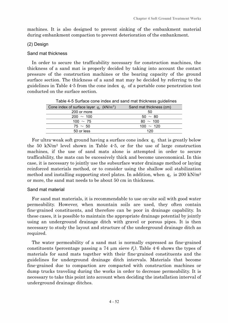
Chapter 4 Soft Ground Treatment Works
4 - 52
machines. It is also designed to prevent sinking of the embankment material during embankment compaction to prevent deterioration of the embankment.
(2) Design
Sand mat thickness
In order to secure the trafficability necessary for construction machines, the thickness of a sand mat is properly decided by taking into account the contact pressure of the construction machines or the bearing capacity of the ground surface section. The thickness of a sand mat may be decided by referring to the guidelines in Table 4-5 from the cone index of a portable cone penetration test conducted on the surface section.
Table 4-5 Surface cone index and sand mat thickness guidelines
Cone index of surface layer (kN/ ) Sand mat thickness (cm) 200 or more 50 200 ~ 100 50 ~ 80 100 ~ 75 80 ~ 100 75 ~ 50 100 ~ 120 50 or less 120
For ultra-weak soft ground having a surface cone index that is greatly below the 50 kN/m2 level shown in Table 4-5, or for the use of large construction machines, if the use of sand mats alone is attempted in order to secure trafficability, the mats can be excessively thick and become uneconomical. In this case, it is necessary to jointly use the subsurface water drainage method or laying reinforced materials method, or to consider using the shallow soil stabilization method and installing supporting steel plates. In addition, when is 200 kN/m2 or more, the sand mat needs to be about 50 cm in thickness.
Sand mat material
For sand mat materials, it is recommendable to use on-site soil with good water permeability. However, when mountain soils are used, they often contain fine-grained constituents, and therefore can be poor in drainage capability. In these cases, it is possible to maintain the appropriate drainage potential by jointly using an underground drainage ditch with gravel or porous pipes. It is then necessary to study the layout and structure of the underground drainage ditch as required.
The water permeability of a sand mat is normally expressed as fine-grained constituents (percentage passing a 74 µm sieve ). Table 4-6 shows the types of materials for sand mats together with their fine-grained constituents and the guidelines for underground drainage ditch intervals. Materials that become fine-grained due to compaction are compacted with construction machines or dump trucks traveling during the works in order to decrease permeability. It is necessary to take this point into account when deciding the installation interval of underground drainage ditches.
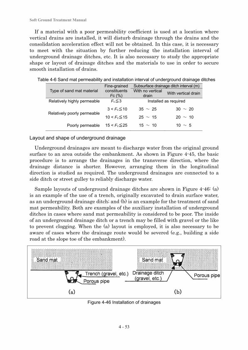
Soft Ground Treatment Manual
4 - 53
If a material with a poor permeability coefficient is used at a location where vertical drains are installed, it will disturb drainage through the drains and the consolidation acceleration effect will not be obtained. In this case, it is necessary to meet with the situation by further reducing the installation interval of underground drainage ditches, etc. It is also necessary to study the appropriate shape or layout of drainage ditches and the materials to use in order to secure smooth installation of drains.
Table 4-6 Sand mat permeability and installation interval of underground drainage ditches
Type of sand mat material Fine-grained constituents
Fc (%)
Subsurface drainage ditch interval (m) With no vertical
drain With vertical drain
Relatively highly permeable Fc≦3 Installed as required
Relatively poorly permeable 3 < Fc≦10 35 ~ 25 30 ~ 20
10 < Fc≦15 25 ~ 15 20 ~ 10
Poorly permeable 15 < Fc≦25 15 ~ 10 10 ~ 5
Layout and shape of underground drainage
Underground drainages are meant to discharge water from the original ground surface to an area outside the embankment. As shown in Figure 4-45, the basic procedure is to arrange the drainages in the transverse direction, where the drainage distance is shorter. However, arranging them in the longitudinal direction is studied as required. The underground drainages are connected to a side ditch or street gulley to reliably discharge water.
Sample layouts of underground drainage ditches are shown in Figure 4-46: (a) is an example of the use of a trench, originally excavated to drain surface water, as an underground drainage ditch; and (b) is an example for the treatment of sand mat permeability. Both are examples of the auxiliary installation of underground ditches in cases where sand mat permeability is considered to be poor. The inside of an underground drainage ditch or a trench may be filled with gravel or the like to prevent clogging. When the (a) layout is employed, it is also necessary to be aware of cases where the drainage route would be severed (e.g., building a side road at the slope toe of the embankment).
Figure 4-46 Installation of drainages
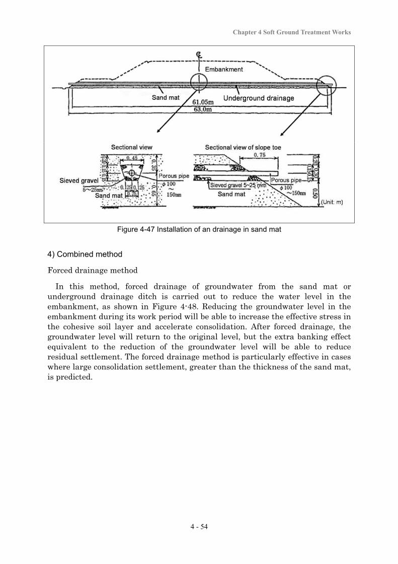
Chapter 4 Soft Ground Treatment Works
4 - 54
Figure 4-47 Installation of an drainage in sand mat
4) Combined method
Forced drainage method
In this method, forced drainage of groundwater from the sand mat or underground drainage ditch is carried out to reduce the water level in the embankment, as shown in Figure 4-48. Reducing the groundwater level in the embankment during its work period will be able to increase the effective stress in the cohesive soil layer and accelerate consolidation. After forced drainage, the groundwater level will return to the original level, but the extra banking effect equivalent to the reduction of the groundwater level will be able to reduce residual settlement. The forced drainage method is particularly effective in cases where large consolidation settlement, greater than the thickness of the sand mat, is predicted.
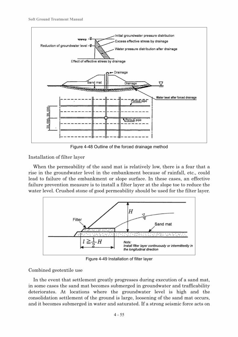
Soft Ground Treatment Manual
4 - 55
Figure 4-48 Outline of the forced drainage method
Installation of filter layer
When the permeability of the sand mat is relatively low, there is a fear that a rise in the groundwater level in the embankment because of rainfall, etc., could lead to failure of the embankment or slope surface. In these cases, an effective failure prevention measure is to install a filter layer at the slope toe to reduce the water level. Crushed stone of good permeability should be used for the filter layer.
Figure 4-49 Installation of filter layer
Combined geotextile use
In the event that settlement greatly progresses during execution of a sand mat, in some cases the sand mat becomes submerged in groundwater and trafficability deteriorates. At locations where the groundwater level is high and the consolidation settlement of the ground is large, loosening of the sand mat occurs, and it becomes submerged in water and saturated. If a strong seismic force acts on
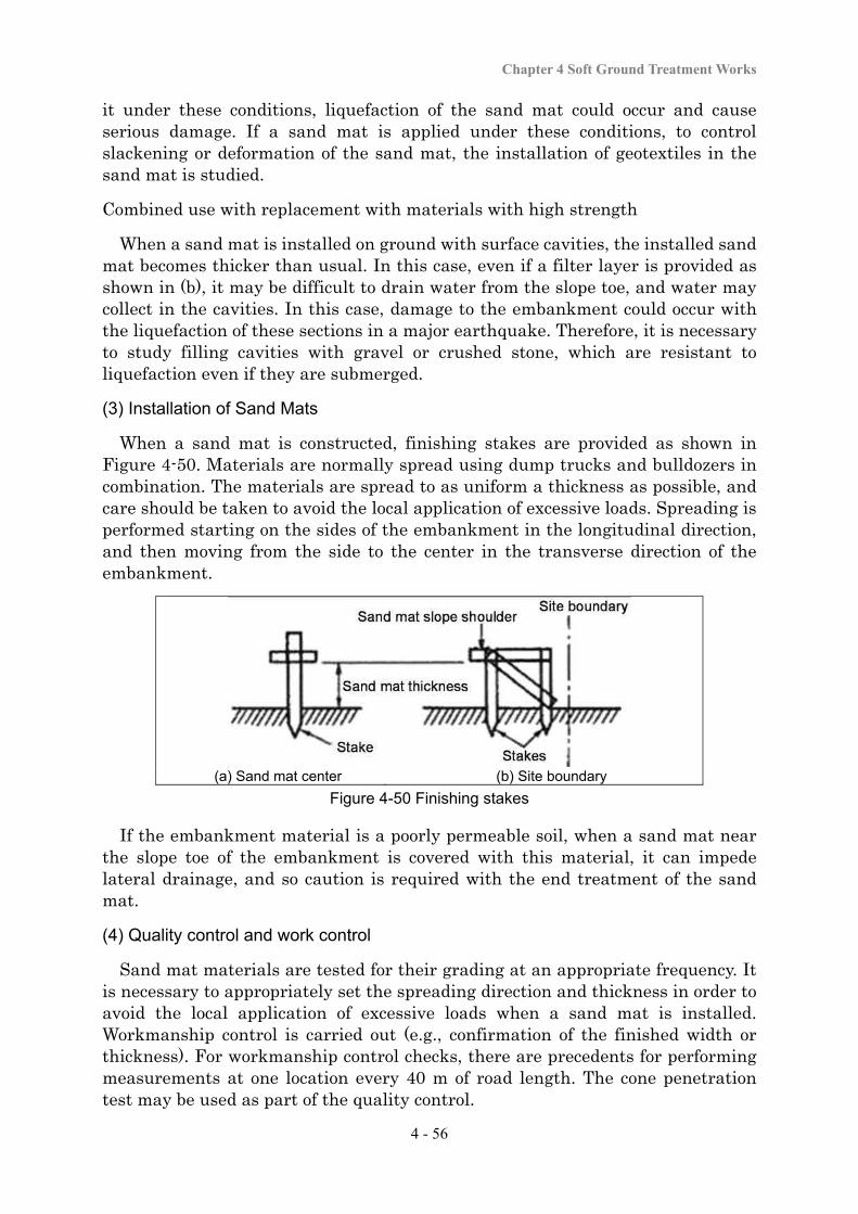
Chapter 4 Soft Ground Treatment Works
4 - 56
it under these conditions, liquefaction of the sand mat could occur and cause serious damage. If a sand mat is applied under these conditions, to control slackening or deformation of the sand mat, the installation of geotextiles in the sand mat is studied.
Combined use with replacement with materials with high strength
When a sand mat is installed on ground with surface cavities, the installed sand mat becomes thicker than usual. In this case, even if a filter layer is provided as shown in (b), it may be difficult to drain water from the slope toe, and water may collect in the cavities. In this case, damage to the embankment could occur with the liquefaction of these sections in a major earthquake. Therefore, it is necessary to study filling cavities with gravel or crushed stone, which are resistant to liquefaction even if they are submerged. (3) Installation of Sand Mats
When a sand mat is constructed, finishing stakes are provided as shown in Figure 4-50. Materials are normally spread using dump trucks and bulldozers in combination. The materials are spread to as uniform a thickness as possible, and care should be taken to avoid the local application of excessive loads. Spreading is performed starting on the sides of the embankment in the longitudinal direction, and then moving from the side to the center in the transverse direction of the embankment.
(a) Sand mat center (b) Site boundary
Figure 4-50 Finishing stakes
If the embankment material is a poorly permeable soil, when a sand mat near the slope toe of the embankment is covered with this material, it can impede lateral drainage, and so caution is required with the end treatment of the sand mat.
(4) Quality control and work control
Sand mat materials are tested for their grading at an appropriate frequency. It is necessary to appropriately set the spreading direction and thickness in order to avoid the local application of excessive loads when a sand mat is installed. Workmanship control is carried out (e.g., confirmation of the finished width or thickness). For workmanship control checks, there are precedents for performing measurements at one location every 40 m of road length. The cone penetration test may be used as part of the quality control.
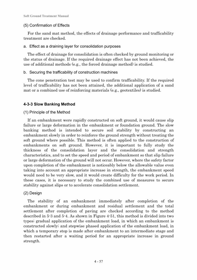
Soft Ground Treatment Manual
4 - 57
(5) Confirmation of Effects
For the sand mat method, the effects of drainage performance and trafficability treatment are checked.
a. Effect as a draining layer for consolidation purposes
The effect of drainage for consolidation is often checked by ground monitoring or the status of drainage. If the required drainage effect has not been achieved, the use of additional methods (e.g., the forced drainage method) is studied.
b. Securing the trafficability of construction machines
The cone penetration test may be used to confirm trafficability. If the required level of trafficability has not been attained, the additional application of a sand mat or a combined use of reinforcing materials (e.g., geotextiles) is studied.
4-3-3 Slow Banking Method
(1) Principle of the Method
If an embankment were rapidly constructed on soft ground, it would cause slip failure or large deformation in the embankment or foundation ground. The slow banking method is intended to secure soil stability by constructing an embankment slowly in order to reinforce the ground strength without treating the soft ground where possible. This method is often applied to the construction of embankments on soft ground. However, it is important to fully study the thickness of the consolidation layer and the consolidation and strength characteristics, and to set the speed and period of embankment so that slip failure or large deformation of the ground will not occur. However, where the safety factor upon completion of the embankment is noticeably below the allowable value even taking into account an appropriate increase in strength, the embankment speed would need to be very slow, and it would create difficulty for the work period. In these cases, it is necessary to study the combined use of measures to secure stability against slips or to accelerate consolidation settlement.
(2) Design
The stability of an embankment immediately after completion of the embankment or during embankment and residual settlement and the total settlement after completion of paving are checked according to the method described in 5-3 and 5-4. As shown in Figure 4-51, this method is divided into two types; gradual application of the embankment load, in which an embankment is constructed slowly; and stepwise phased application of the embankment load, in which a temporary stop is made after embankment to an intermediate stage and then restarted after a waiting period for an appropriate increase in ground strength.
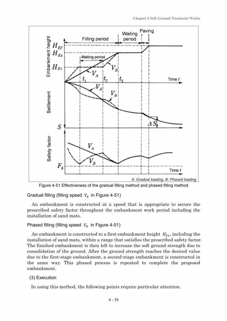
Chapter 4 Soft Ground Treatment Works
4 - 58
A: Gradual loading, B: Phased loading
Figure 4-51 Effectiveness of the gradual filling method and phased filling method
Gradual filling (filling speed in Figure 4-51)
An embankment is constructed at a speed that is appropriate to secure the prescribed safety factor throughout the embankment work period including the installation of sand mats.
Phased filling (filling speed in Figure 4-51)
An embankment is constructed to a first embankment height , including the installation of sand mats, within a range that satisfies the prescribed safety factor. The finished embankment is then left to increase the soft ground strength due to consolidation of the ground. After the ground strength reaches the desired value due to the first-stage embankment, a second-stage embankment is constructed in the same way. This phased process is repeated to complete the proposed embankment.
(3) Execution
In using this method, the following points require particular attention.
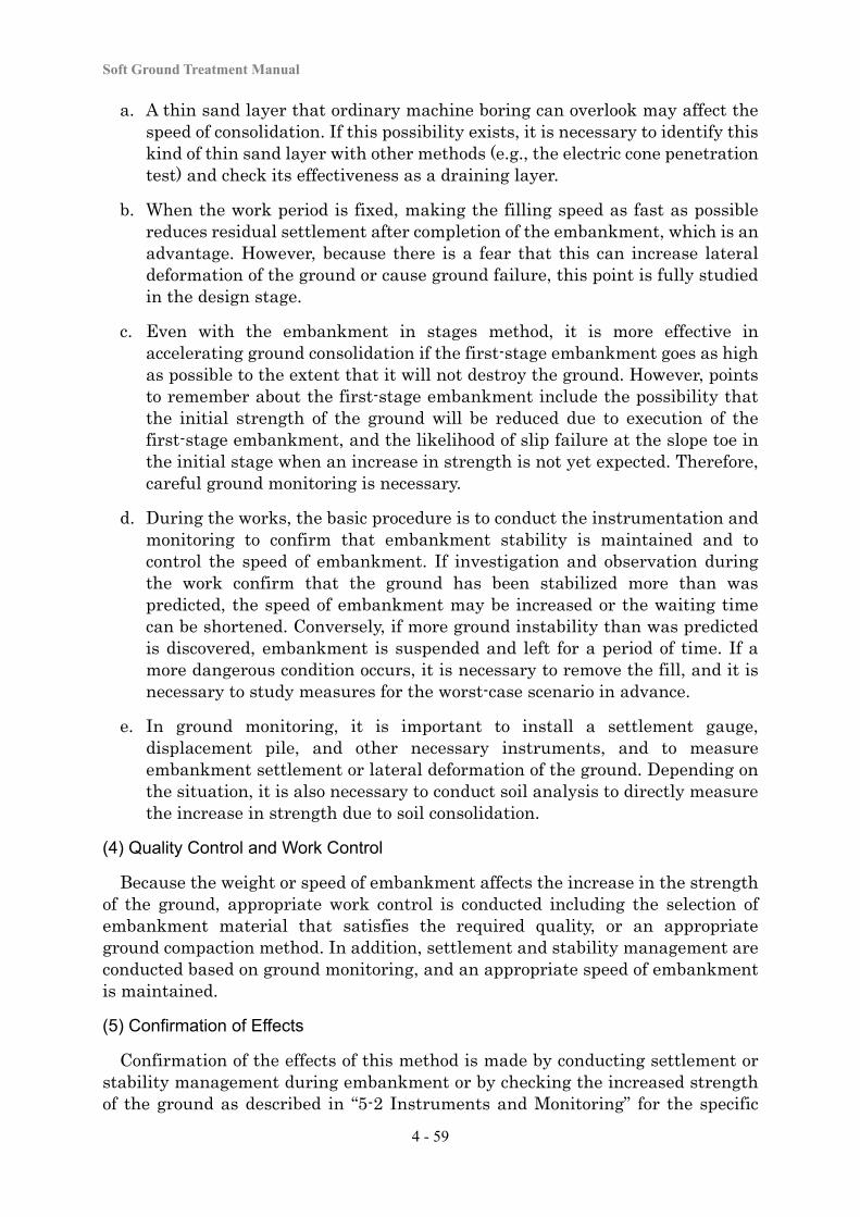
Soft Ground Treatment Manual
4 - 59
a. A thin sand layer that ordinary machine boring can overlook may affect the speed of consolidation. If this possibility exists, it is necessary to identify this kind of thin sand layer with other methods (e.g., the electric cone penetration test) and check its effectiveness as a draining layer.
b. When the work period is fixed, making the filling speed as fast as possible reduces residual settlement after completion of the embankment, which is an advantage. However, because there is a fear that this can increase lateral deformation of the ground or cause ground failure, this point is fully studied in the design stage.
c. Even with the embankment in stages method, it is more effective in accelerating ground consolidation if the first-stage embankment goes as high as possible to the extent that it will not destroy the ground. However, points to remember about the first-stage embankment include the possibility that the initial strength of the ground will be reduced due to execution of the first-stage embankment, and the likelihood of slip failure at the slope toe in the initial stage when an increase in strength is not yet expected. Therefore, careful ground monitoring is necessary.
d. During the works, the basic procedure is to conduct the instrumentation and monitoring to confirm that embankment stability is maintained and to control the speed of embankment. If investigation and observation during the work confirm that the ground has been stabilized more than was predicted, the speed of embankment may be increased or the waiting time can be shortened. Conversely, if more ground instability than was predicted is discovered, embankment is suspended and left for a period of time. If a more dangerous condition occurs, it is necessary to remove the fill, and it is necessary to study measures for the worst-case scenario in advance.
e. In ground monitoring, it is important to install a settlement gauge, displacement pile, and other necessary instruments, and to measure embankment settlement or lateral deformation of the ground. Depending on the situation, it is also necessary to conduct soil analysis to directly measure the increase in strength due to soil consolidation.
(4) Quality Control and Work Control
Because the weight or speed of embankment affects the increase in the strength of the ground, appropriate work control is conducted including the selection of embankment material that satisfies the required quality, or an appropriate ground compaction method. In addition, settlement and stability management are conducted based on ground monitoring, and an appropriate speed of embankment is maintained.
(5) Confirmation of Effects
Confirmation of the effects of this method is made by conducting settlement or stability management during embankment or by checking the increased strength of the ground as described in “5-2 Instruments and Monitoring” for the specific
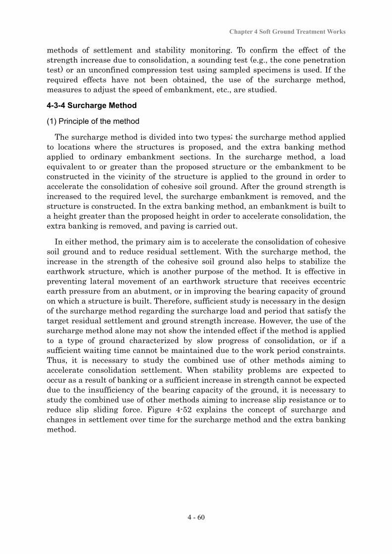
Chapter 4 Soft Ground Treatment Works
4 - 60
methods of settlement and stability monitoring. To confirm the effect of the strength increase due to consolidation, a sounding test (e.g., the cone penetration test) or an unconfined compression test using sampled specimens is used. If the required effects have not been obtained, the use of the surcharge method, measures to adjust the speed of embankment, etc., are studied.
4-3-4 Surcharge Method
(1) Principle of the method
The surcharge method is divided into two types; the surcharge method applied to locations where the structures is proposed, and the extra banking method applied to ordinary embankment sections. In the surcharge method, a load equivalent to or greater than the proposed structure or the embankment to be constructed in the vicinity of the structure is applied to the ground in order to accelerate the consolidation of cohesive soil ground. After the ground strength is increased to the required level, the surcharge embankment is removed, and the structure is constructed. In the extra banking method, an embankment is built to a height greater than the proposed height in order to accelerate consolidation, the extra banking is removed, and paving is carried out.
In either method, the primary aim is to accelerate the consolidation of cohesive soil ground and to reduce residual settlement. With the surcharge method, the increase in the strength of the cohesive soil ground also helps to stabilize the earthwork structure, which is another purpose of the method. It is effective in preventing lateral movement of an earthwork structure that receives eccentric earth pressure from an abutment, or in improving the bearing capacity of ground on which a structure is built. Therefore, sufficient study is necessary in the design of the surcharge method regarding the surcharge load and period that satisfy the target residual settlement and ground strength increase. However, the use of the surcharge method alone may not show the intended effect if the method is applied to a type of ground characterized by slow progress of consolidation, or if a sufficient waiting time cannot be maintained due to the work period constraints. Thus, it is necessary to study the combined use of other methods aiming to accelerate consolidation settlement. When stability problems are expected to occur as a result of banking or a sufficient increase in strength cannot be expected due to the insufficiency of the bearing capacity of the ground, it is necessary to study the combined use of other methods aiming to increase slip resistance or to reduce slip sliding force. Figure 4-52 explains the concept of surcharge and changes in settlement over time for the surcharge method and the extra banking method.
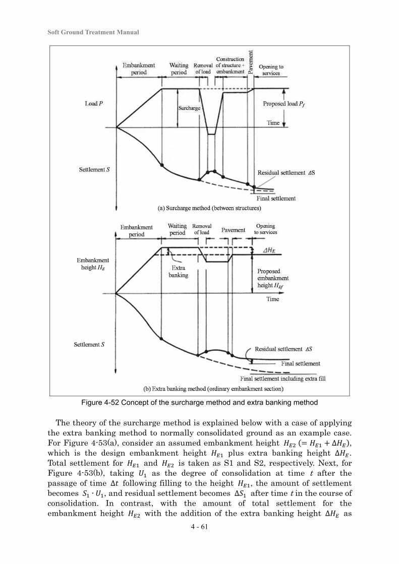
Soft Ground Treatment Manual
4 - 61
Figure 4-52 Concept of the surcharge method and extra banking method
The theory of the surcharge method is explained below with a case of applying the extra banking method to normally consolidated ground as an example case. For Figure 4-53(a), consider an assumed embankment height ∆ , which is the design embankment height plus extra banking height ∆ . Total settlement for and is taken as S1 and S2, respectively. Next, for Figure 4-53(b), taking as the degree of consolidation at time t after the passage of time ∆ following filling to the height , the amount of settlement becomes ∙ , and residual settlement becomes ∆ after time t in the course of consolidation. In contrast, with the amount of total settlement for the embankment height with the addition of the extra banking height ∆ as

Chapter 4 Soft Ground Treatment Works
4 - 62
, because the degree of consolidation at time t is generally , the settlement becomes ∙ . At this point in time, if ∆ is removed, the degree of consolidation ∆ has been reached as shown in Figure 4-53(a) for the embankment height . In other words, the degree of consolidation that only reached under the design embankment height has received an extra amount ∆ by loading with the extra banking ∆ for the period of time ∆ . In reality, the extra banking is not applied instantaneously, and some expansion occurs during load removal, and the effect of consolidation acceleration is lost to that extent. However, with the extra banking ∆ and a sufficient loading period of time ∆ , residual settlement after the passage of time t can be reduced from ∆ to ∆ as shown in Figure 4-53(b).
(a) Relationship between embankment height
and settlement (b) Relationship between settlement and time
Figure 4-53 Theory of the surcharge method
(2) Design
The settlement and stability of an embankment are studied with the methods described in “3-2-2” and “3-2-3”. To be specific, studies are performed regarding the stability of the embankment, including the surcharge load and extra banking, immediately after the completion of embankment or during embankment, and residual settlement of the structure after the removal of the surcharge. When applying the surcharge method, the surcharge load and period are decided so that sufficient required ground strength and residual settlement are within the allowed values.
(3) Execution
For determining the surcharge load and period, there are relationships among various factors, including the consolidation layer thickness or soil properties, the settlement-time curve relationship, the earthwork structure load, and the work period. Therefore, it is necessary to pay attention to the following points in applying this method.

Soft Ground Treatment Manual
4 - 63
a. Since the load of the embankment affects consolidation settlement and the strength increase of the ground, it is important to correctly understand the unit weight.
b. With this method, it is effective to apply a surcharge load that is as large as possible and to have a long waiting time, as shown in Figure 4-53. However, with a thick consolidation layer, and for ground characterized by a small consolidation coefficient and slow progress of consolidation, it is recommendable to study the combined use of another method (e.g., the vertical drain method).
c. It is recommendable to directly obtain information on increasing ground strength by appropriate means (e.g., a boring survey) before the removal of the surcharge.
d. For the top width of the surcharge, as much as possible it is recommendable to provide a marginal width as shown in Figure 4-15. Since there are also cases in which the surcharge will not be able to produce the expected effect depending on the location of the structure (e.g., the inability to apply the surcharge because part of the proposed section is in a river area), it is necessary to study the work procedures even in the design stage.
e. There are cases in which the reuse of a material used for a surcharge in a different construction project may provide an economic benefit. It is recommendable to formulate a schedule so that material like this can be reused in adjacent work.
f. During the works, it is necessary to conduct sufficient ground monitoring to detect any sign of ground slip failure and to evaluate the residual settlement after the removal of the surcharge or the surcharge removal timing based on the observation results.
g. When a structure is constructed on a raft foundation, the removal of the surcharge can generate elastic uplift (rebound), and if a structure is constructed on it, the ground will settle again. Therefore, in setting the structure height, it is necessary to allow for changes like these.
(4) Quality Control and Work Control
Since the weight of the embankment affects the amount of consolidation settlement or acceleration of ground strength increase, it is necessary to properly conduct settlement and stability management based on ground monitoring in order to decide the surcharge timing, in addition to work control covering the quality of the embankment material, the workmanship of the surcharge, or the degree of consolidation.
(5) Confirmation of effects
The effects of the method as measured by the amount of consolidation settlement during surcharge or strength increase due to consolidation are confirmed. The confirmation method is the same as that specified by “4-3-3 Slow
Chapter 4 Soft Ground Treatment Works
4 - 64
Banking Method”. When it is considered that no prescribed effect has been realized, other measures are studied (e.g., adjustment of the surcharge or the surcharge timing).
4-3-5 Sand Drain Method
(1) Principle of the method
As a method belonging to the vertical drain method group, in the sand drain method, columns with highly permeable sand (“sand drains”) are created vertically in the ground in order to shorten the drainage distance in the horizontal direction to accelerate consolidation and ground strength increase. Depending on the sand drain installation procedure, the method is divided into the vibro hammer method, the auger method, and the bagging method. In areas where it is difficult to procure highly permeable sand, in some cases gravel or crushed stone is used instead. Drains in the vibro hammer or auger method are 40 to 50 cm in diameter and are installed in the ground at an interval of about 1.5 m to 3.5 m. In the bagging method, sand is filled in a strong net bag about 12 cm in diameter, and these sandbags are placed in the ground. Normally, four columns of sandbags laid out in a square at a pitch of 1.2 m are installed at the same time.
The sand drain method is rarely employed alone, but is often used together with the slow banking method or surcharge method. Although it is effective for uniform cohesive soil ground with a great layer thickness, the consolidation acceleration effect is relatively small when it is applied to ground with many interbedded sand layers or peaty ground with high permeability.
As the time t necessary for consolidation of an untreated cohesive soil layer is proportional to the square of the drainage distance H, consolidation takes a long time when the cohesive layer is thick. However, when sand drains are installed in the soft layer, the drainage distance in the horizontal direction is reduced, and the consolidation time is shortened. In applying the sand drain method, it is important to evaluate the use of this method based on a full study of the thickness of the consolidation layer or consolidation characteristics, and, if the decision is to use this method, to appropriately consider the area of treatment, the layout of the sand piles, the installation depth, the material to use, and the execution method.
(2) Design
The target degree of consolidation is studied based on the study of embankment stability and residual settlement taking into account the strength increase of the cohesive soil, according to the methods described in “3-2-2” and “3-2-3”. The relationship between the degree of consolidation and the consolidation time is calculated, and a drain installation interval that satisfies the target degree of consolidation is decided. Stability and settlement are then studied based on the specific treatment specifications to check if the set values are appropriate. In many cases the target degree of consolidation is set to about 80 to 90%. Although it depends on the proposed schedule, the leaving time for consolidation is often 3
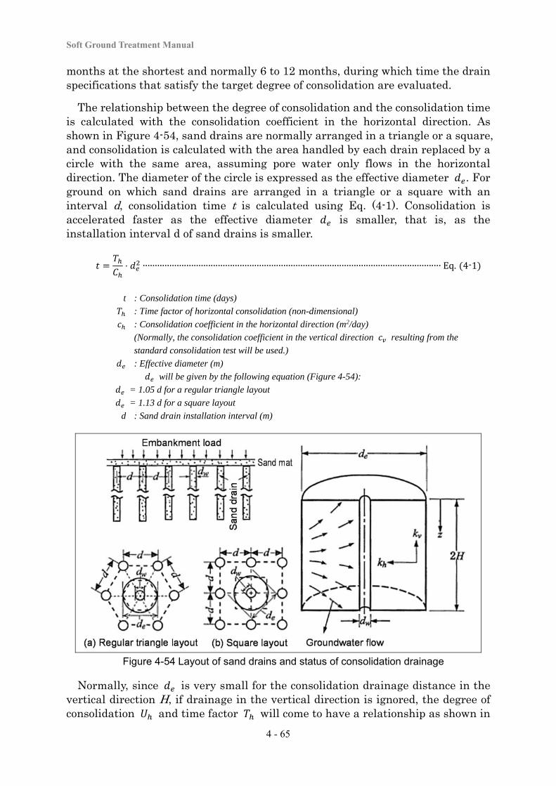
Soft Ground Treatment Manual
4 - 65
months at the shortest and normally 6 to 12 months, during which time the drain specifications that satisfy the target degree of consolidation are evaluated.
The relationship between the degree of consolidation and the consolidation time is calculated with the consolidation coefficient in the horizontal direction. As shown in Figure 4-54, sand drains are normally arranged in a triangle or a square, and consolidation is calculated with the area handled by each drain replaced by a circle with the same area, assuming pore water only flows in the horizontal direction. The diameter of the circle is expressed as the effective diameter . For ground on which sand drains are arranged in a triangle or a square with an interval d, consolidation time t is calculated using Eq. (4-1). Consolidation is accelerated faster as the effective diameter is smaller, that is, as the installation interval d of sand drains is smaller.
⋅ ∙∙∙∙∙∙∙∙∙∙∙∙∙∙∙∙∙∙∙∙∙∙∙∙∙∙∙∙∙∙∙∙∙∙∙∙∙∙∙∙∙∙∙∙∙∙∙∙∙∙∙∙∙∙∙∙∙∙∙∙∙∙∙∙∙∙∙∙∙∙∙∙∙∙∙∙∙∙∙∙∙∙∙∙∙∙∙∙∙∙∙∙∙∙∙∙∙∙∙∙∙∙∙∙∙∙∙∙∙∙∙∙∙∙∙∙∙∙∙∙∙∙∙ Eq. 4-1
t : Consolidation time (days)
: Time factor of horizontal consolidation (non-dimensional)
: Consolidation coefficient in the horizontal direction (m2/day)
(Normally, the consolidation coefficient in the vertical direction resulting from the
standard consolidation test will be used.)
: Effective diameter (m)
will be given by the following equation (Figure 4-54):
= 1.05 d for a regular triangle layout
= 1.13 d for a square layout
d : Sand drain installation interval (m)
Figure 4-54 Layout of sand drains and status of consolidation drainage
Normally, since is very small for the consolidation drainage distance in the vertical direction H, if drainage in the vertical direction is ignored, the degree of consolidation and time factor will come to have a relationship as shown in
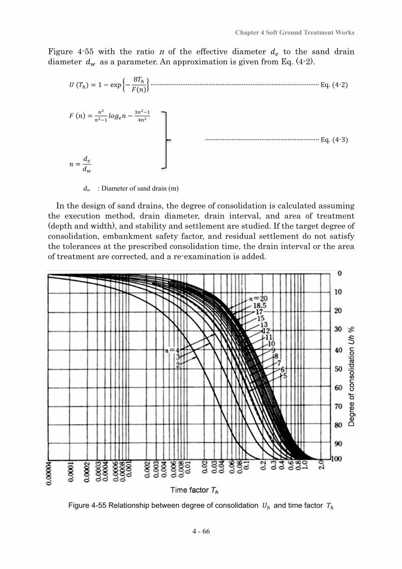
Chapter 4 Soft Ground Treatment Works
4 - 66
Figure 4-55 with the ratio n of the effective diameter to the sand drain diameter as a parameter. An approximation is given from Eq. (4-2).
1 exp8
∙∙∙∙∙∙∙∙∙∙∙∙∙∙∙∙∙∙∙∙∙∙∙∙∙∙∙∙∙∙∙∙∙∙∙∙∙∙∙∙∙∙∙∙∙∙∙∙∙∙∙∙∙∙∙∙∙∙∙∙∙∙∙∙∙∙∙∙∙∙∙∙∙∙∙∙∙∙∙∙∙∙∙∙∙∙∙∙∙∙∙∙∙∙∙∙ Eq. 4-2
∙∙∙∙∙∙∙∙∙∙∙∙∙∙∙∙∙∙∙∙∙∙∙∙∙∙∙∙∙∙∙∙∙∙∙∙∙∙∙∙∙∙∙∙∙∙∙∙∙∙∙∙∙∙∙∙∙∙∙∙∙∙∙∙∙ Eq. 4-3
dw : Diameter of sand drain (m)
In the design of sand drains, the degree of consolidation is calculated assuming the execution method, drain diameter, drain interval, and area of treatment (depth and width), and stability and settlement are studied. If the target degree of consolidation, embankment safety factor, and residual settlement do not satisfy the tolerances at the prescribed consolidation time, the drain interval or the area of treatment are corrected, and a re-examination is added.
Figure 4-55 Relationship between degree of consolidation and time factor
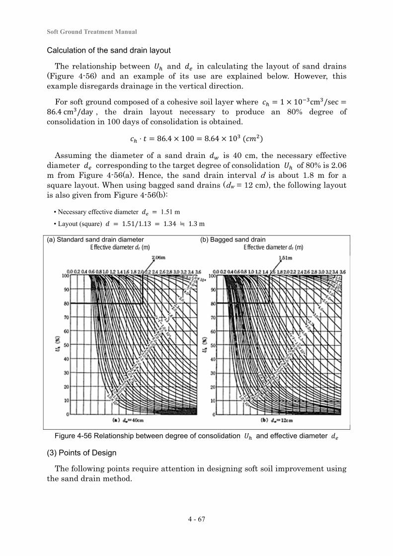
Soft Ground Treatment Manual
4 - 67
Calculation of the sand drain layout
The relationship between and in calculating the layout of sand drains (Figure 4-56) and an example of its use are explained below. However, this example disregards drainage in the vertical direction.
For soft ground composed of a cohesive soil layer where 1 10 cm /sec86.4cm /day , the drain layout necessary to produce an 80% degree of consolidation in 100 days of consolidation is obtained.
⋅ 86.4 100 8.64 10
Assuming the diameter of a sand drain is 40 cm, the necessary effective diameter corresponding to the target degree of consolidation of 80% is 2.06 m from Figure 4-56(a). Hence, the sand drain interval d is about 1.8 m for a square layout. When using bagged sand drains (dw = 12 cm), the following layout is also given from Figure 4-56(b):
• Necessary effective diameter 1.51 m
• Layout (square) 1.51/1.13 1.34 ≒ 1.3m
(a) Standard sand drain diameter (b) Bagged sand drain Effective diameter de (m) Effective diameter de (m)
Figure 4-56 Relationship between degree of consolidation and effective diameter
(3) Points of Design
The following points require attention in designing soft soil improvement using the sand drain method.
Chapter 4 Soft Ground Treatment Works
4 - 68
Presence of a sand layer in the soft layer
The sand drain method has been used in a large number of projects, and there have been many comments on its effectiveness. According to a study on cases in which this method (including the prefabricated vertical drain method) failed to show the expected results compared with cases of no treatment, cohesive soil ground with unsuccessful application of this method is often characterized by the presence of many thin interbedded sand layers in the ground. This means that in those types of ground the speed of consolidation is fast from the beginning and does not need any consolidation acceleration with drains. Therefore, it is necessary to pay full attention to the presence of interbedded sand layers in the cohesive soil layer when this method is used.
Prevention of surrounding soil disturbance
When sand drains are installed, the surrounding soil can be seriously disturbed, and this may cause reduction in water permeability or ground strength. To avoid this, it is necessary to select a execution method that is suitable for the ground conditions, and to select on an appropriate sand drain installation interval.
Sand drain material
Sand drains serve as a path to collect and discharge pore water released from the consolidated soft layer for a long period of time. Therefore, so that the drains can show sufficient water permeability performance as a pathway for a long period of time, it is necessary to use a suitable material that does not cause blockage or other problems. The guidelines for drain material grading are shown below.
drainmaterial / surroundingcohesivesoil 4 ∙∙∙∙∙∙∙∙∙∙∙∙∙∙∙∙∙∙∙∙∙∙∙∙∙∙∙∙∙∙∙∙∙∙∙∙∙∙∙∙ Eq. 4-4
drainmaterial / surroundingcohesivesoil 4 ∙∙∙∙∙∙∙∙∙∙∙∙∙∙∙∙∙∙∙∙∙∙∙∙∙∙∙∙∙∙∙∙∙∙∙∙∙∙∙∙ Eq. 4-5
Where and have a grain size equivalent to 15% and 85%, respectively, of the weight percent passing in the grain size accumulation curve. When it is difficult to procure materials with such a grading, it is acceptable to use clean sand, gravel, or crushed stone with high permeability.
Water permeability of sand drains and sand mats
In the consolidation calculation, the permeability coefficients of drains and sand mats are assumed to be infinite. However, in reality, drains and sand mats both have finite permeability coefficients. Depending on the value of the permeability coefficient, head loss may occur in a drain or a sand mat and reduce the drainage performance, thus causing delay in consolidation. When this problem is evaluated quantitatively in terms of the relationship between the degree of consolidation and time factor , a coefficient called the well resistance coefficient is used for sand drains as shown in Eq. (4-7).
1 exp80.8
∙∙∙∙∙∙∙∙∙∙∙∙∙∙∙∙∙∙∙∙∙∙∙∙∙∙∙∙∙∙∙∙∙∙∙∙∙∙∙∙∙∙∙∙∙∙∙∙∙∙∙∙∙∙∙∙∙∙∙∙∙∙∙∙∙∙∙∙∙∙∙∙∙∙ Eq. 4-6
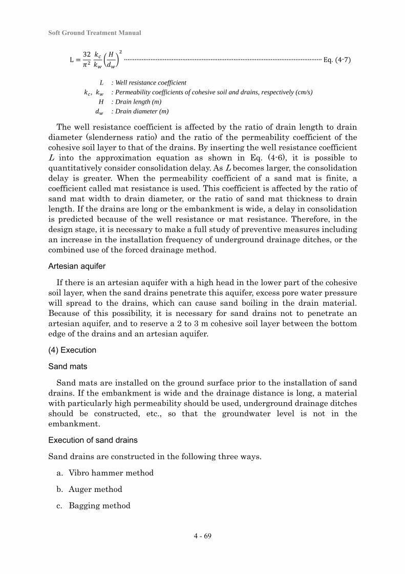
Soft Ground Treatment Manual
4 - 69
L32 ∙∙∙∙∙∙∙∙∙∙∙∙∙∙∙∙∙∙∙∙∙∙∙∙∙∙∙∙∙∙∙∙∙∙∙∙∙∙∙∙∙∙∙∙∙∙∙∙∙∙∙∙∙∙∙∙∙∙∙∙∙∙∙∙∙∙∙∙∙∙∙∙∙∙∙∙∙∙∙∙∙∙∙∙∙∙∙∙∙∙∙∙∙∙∙∙∙∙∙∙∙∙∙∙∙∙∙∙∙∙∙∙ Eq. 4-7
L : Well resistance coefficient
, : Permeability coefficients of cohesive soil and drains, respectively (cm/s)
H : Drain length (m)
: Drain diameter (m)
The well resistance coefficient is affected by the ratio of drain length to drain diameter (slenderness ratio) and the ratio of the permeability coefficient of the cohesive soil layer to that of the drains. By inserting the well resistance coefficient L into the approximation equation as shown in Eq. (4-6), it is possible to quantitatively consider consolidation delay. As L becomes larger, the consolidation delay is greater. When the permeability coefficient of a sand mat is finite, a coefficient called mat resistance is used. This coefficient is affected by the ratio of sand mat width to drain diameter, or the ratio of sand mat thickness to drain length. If the drains are long or the embankment is wide, a delay in consolidation is predicted because of the well resistance or mat resistance. Therefore, in the design stage, it is necessary to make a full study of preventive measures including an increase in the installation frequency of underground drainage ditches, or the combined use of the forced drainage method.
Artesian aquifer
If there is an artesian aquifer with a high head in the lower part of the cohesive soil layer, when the sand drains penetrate this aquifer, excess pore water pressure will spread to the drains, which can cause sand boiling in the drain material. Because of this possibility, it is necessary for sand drains not to penetrate an artesian aquifer, and to reserve a 2 to 3 m cohesive soil layer between the bottom edge of the drains and an artesian aquifer.
(4) Execution
Sand mats
Sand mats are installed on the ground surface prior to the installation of sand drains. If the embankment is wide and the drainage distance is long, a material with particularly high permeability should be used, underground drainage ditches should be constructed, etc., so that the groundwater level is not in the embankment.
Execution of sand drains
Sand drains are constructed in the following three ways.
a. Vibro hammer method
b. Auger method
c. Bagging method
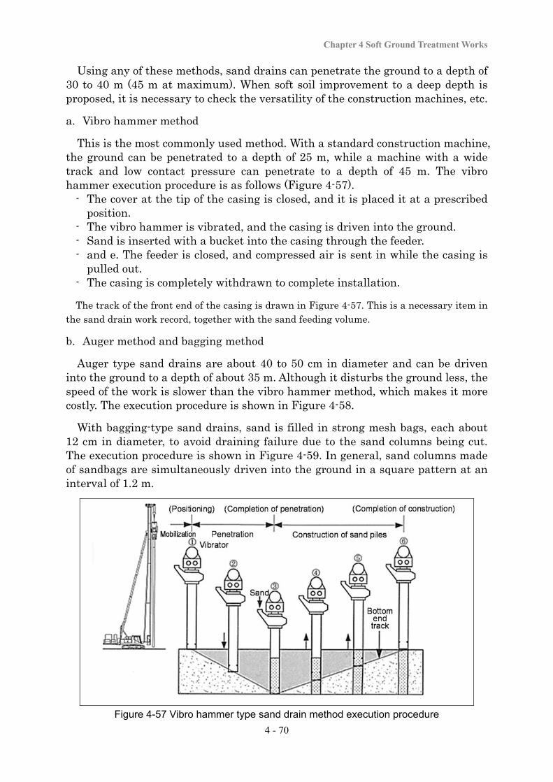
Chapter 4 Soft Ground Treatment Works
4 - 70
Using any of these methods, sand drains can penetrate the ground to a depth of 30 to 40 m (45 m at maximum). When soft soil improvement to a deep depth is proposed, it is necessary to check the versatility of the construction machines, etc.
a. Vibro hammer method
This is the most commonly used method. With a standard construction machine, the ground can be penetrated to a depth of 25 m, while a machine with a wide track and low contact pressure can penetrate to a depth of 45 m. The vibro hammer execution procedure is as follows (Figure 4-57).
- The cover at the tip of the casing is closed, and it is placed it at a prescribed position.
- The vibro hammer is vibrated, and the casing is driven into the ground. - Sand is inserted with a bucket into the casing through the feeder. - and e. The feeder is closed, and compressed air is sent in while the casing is
pulled out. - The casing is completely withdrawn to complete installation.
The track of the front end of the casing is drawn in Figure 4-57. This is a necessary item in the sand drain work record, together with the sand feeding volume.
b. Auger method and bagging method
Auger type sand drains are about 40 to 50 cm in diameter and can be driven into the ground to a depth of about 35 m. Although it disturbs the ground less, the speed of the work is slower than the vibro hammer method, which makes it more costly. The execution procedure is shown in Figure 4-58.
With bagging-type sand drains, sand is filled in strong mesh bags, each about 12 cm in diameter, to avoid draining failure due to the sand columns being cut. The execution procedure is shown in Figure 4-59. In general, sand columns made of sandbags are simultaneously driven into the ground in a square pattern at an interval of 1.2 m.
Figure 4-57 Vibro hammer type sand drain method execution procedure
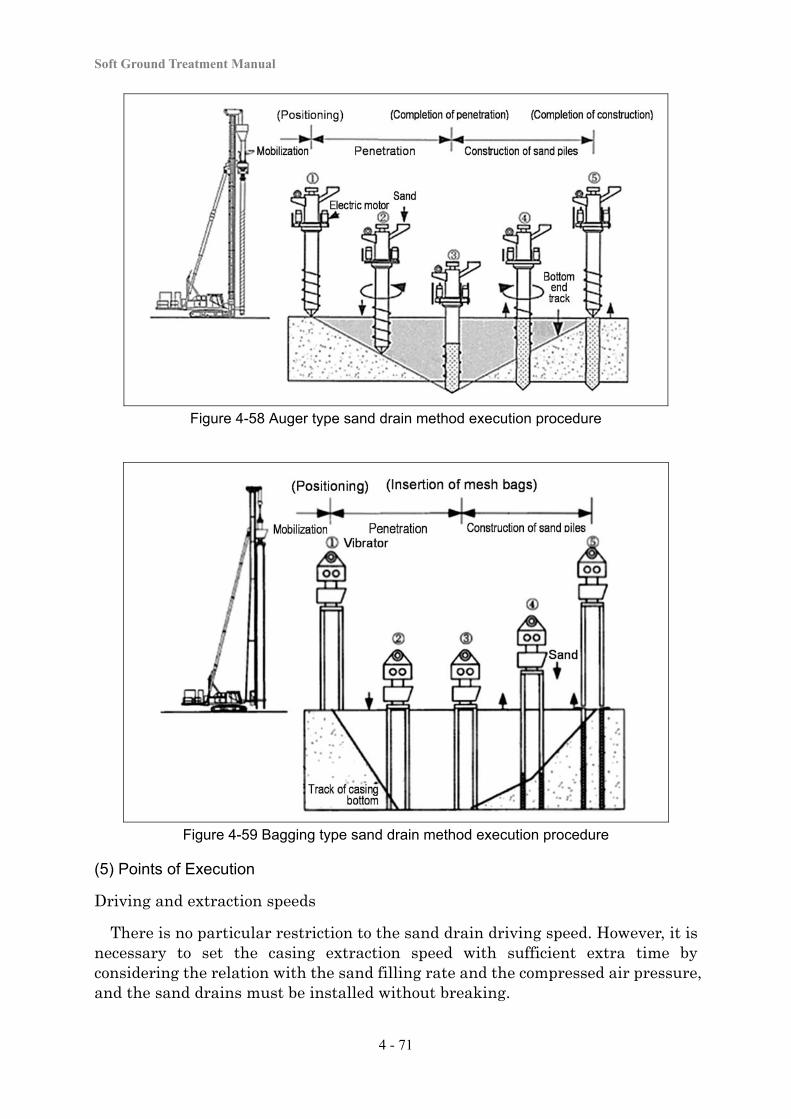
Soft Ground Treatment Manual
4 - 71
Figure 4-58 Auger type sand drain method execution procedure
Figure 4-59 Bagging type sand drain method execution procedure
(5) Points of Execution
Driving and extraction speeds
There is no particular restriction to the sand drain driving speed. However, it is necessary to set the casing extraction speed with sufficient extra time by considering the relation with the sand filling rate and the compressed air pressure, and the sand drains must be installed without breaking.
Chapter 4 Soft Ground Treatment Works
4 - 72
Sand filling and sand amount management
There is a sand filling method in which sand is temporarily put in a bucket to weigh the amount of a single feed, and the bucket is lifted up for feeding to the hopper. In recent years, it is normal to weigh the sand feed with a sand level meter installed inside the casing.
Protection of surrounding structures
When the vibro hammer type sand drain method is used, in some cases various impacts on surrounding structures are caused due to driving the casing into the ground, because of deformation of the surrounding ground or vibration during drilling, and appropriate preventive measures should be taken (e.g., the excavation of trenches for physical separation).
Trafficability
As the installation length increases, the weight of the construction machines becomes larger. As a result, the machines become unstable, and there is a fear that they may flip over. It is therefore necessary to make a preliminary investigation and confirm that is possible to secure trafficability for construction machines. If trafficability is not secured, it is necessary to take appropriate measures (e.g., the installation of sand mats or steel plates). Furthermore, after driving, the ground strength may have been reduced. Therefore, it is recommendable to use steel plates even though trafficability is secured.
(6) Quality control and Work Control
Appropriate management tests are conducted for sand drain materials, including measurement of grain size distribution at an appropriate frequency. When sand drains are installed, it is necessary to check the installation position and interval and installation procedure at an appropriate frequency, and to maintain records of the installation depth, maximum penetration depth, and the sand feeding volume. For the installation depth and the sand feeding volume, the data for all the sand drains are normally recorded.
(7) Confirmation of Effects
The effects of the method are checked by measuring the amount of consolidation settlement and the strength increase due to consolidation. The confirmation method is the same as that for “4-3-3 Slow Banking Method”. If the prescribed effect has not been achieved, the causes are investigated by checking the initial ground investigation results and work control records. If the discovered cause is insufficient sand mat draining performance, necessary measures are studied, including the additional installation of the forced drainage method, the additional application of a surcharge, and extending the loading period.
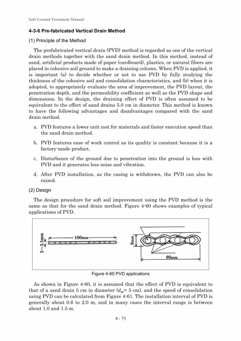
Soft Ground Treatment Manual
4 - 73
4-3-6 Pre-fabricated Vertical Drain Method
(1) Principle of the Method
The prefabricated vertical drain (PVD) method is regarded as one of the vertical drain methods together with the sand drain method. In this method, instead of sand, artificial products made of paper (cardboard), plastics, or natural fibers are placed in cohesive soil ground to make a draining column. When PVD is applied, it is important (a) to decide whether or not to use PVD by fully studying the thickness of the cohesive soil and consolidation characteristics, and (b) when it is adopted, to appropriately evaluate the area of improvement, the PVD layout, the penetration depth, and the permeability coefficient as well as the PVD shape and dimensions. In the design, the draining effect of PVD is often assumed to be equivalent to the effect of sand drains 5.0 cm in diameter. This method is known to have the following advantages and disadvantages compared with the sand drain method.
a. PVD features a lower unit cost for materials and faster execution speed than the sand drain method.
b. PVD features ease of work control as its quality is constant because it is a factory-made product.
c. Disturbance of the ground due to penetration into the ground is less with PVD and it generates less noise and vibration.
d. After PVD installation, as the casing is withdrawn, the PVD can also be raised.
(2) Design
The design procedure for soft soil improvement using the PVD method is the same as that for the sand drain method. Figure 4-60 shows examples of typical applications of PVD.
Figure 4-60 PVD applications
As shown in Figure 4-60, it is assumed that the effect of PVD is equivalent to that of a sand drain 5 cm in diameter ( = 5 cm), and the speed of consolidation using PVD can be calculated from Figure 4-61. The installation interval of PVD is generally about 0.6 to 2.0 m, and in many cases the interval range is between about 1.0 and 1.5 m.
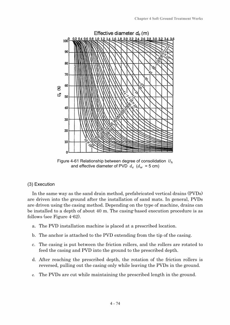
Chapter 4 Soft Ground Treatment Works
4 - 74
Figure 4-61 Relationship between degree of consolidation and effective diameter of PVD ( = 5 cm)
(3) Execution
In the same way as the sand drain method, prefabricated vertical drains (PVDs) are driven into the ground after the installation of sand mats. In general, PVDs are driven using the casing method. Depending on the type of machine, drains can be installed to a depth of about 40 m. The casing-based execution procedure is as follows (see Figure 4-62).
a. The PVD installation machine is placed at a prescribed location.
b. The anchor is attached to the PVD extending from the tip of the casing.
c. The casing is put between the friction rollers, and the rollers are rotated to feed the casing and PVD into the ground to the prescribed depth.
d. After reaching the prescribed depth, the rotation of the friction rollers is reversed, pulling out the casing only while leaving the PVDs in the ground.
e. The PVDs are cut while maintaining the prescribed length in the ground.
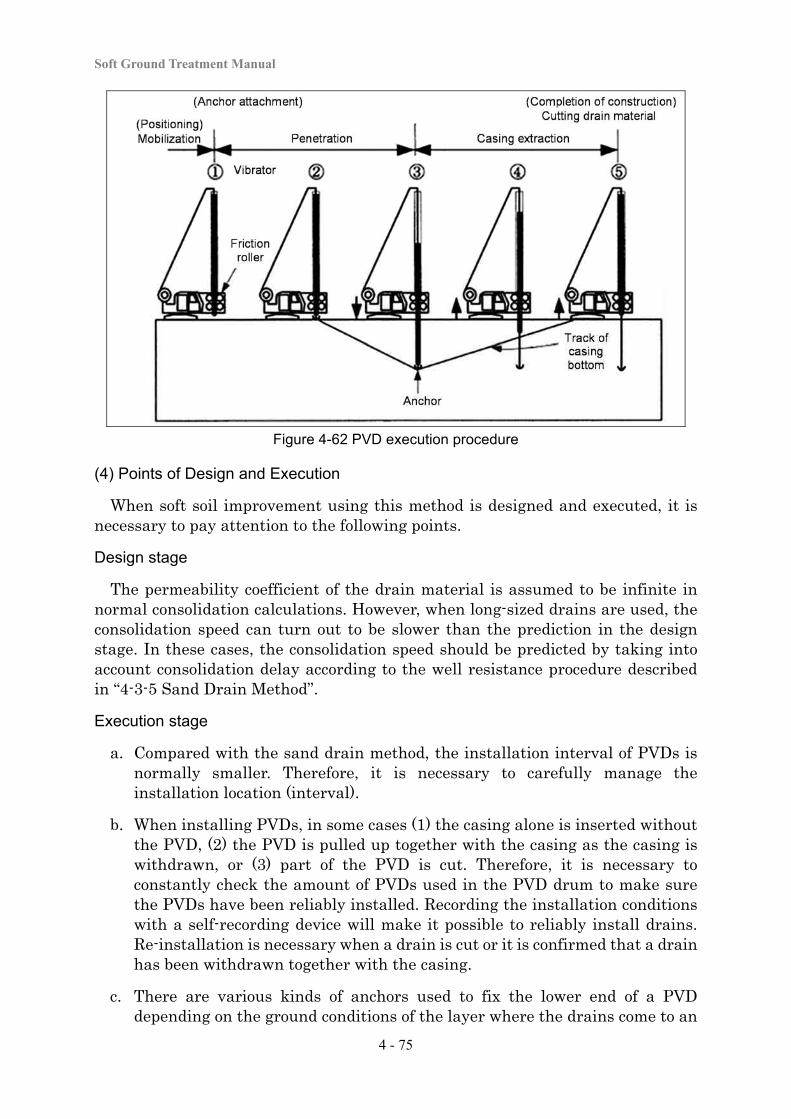
Soft Ground Treatment Manual
4 - 75
Figure 4-62 PVD execution procedure
(4) Points of Design and Execution
When soft soil improvement using this method is designed and executed, it is necessary to pay attention to the following points.
Design stage
The permeability coefficient of the drain material is assumed to be infinite in normal consolidation calculations. However, when long-sized drains are used, the consolidation speed can turn out to be slower than the prediction in the design stage. In these cases, the consolidation speed should be predicted by taking into account consolidation delay according to the well resistance procedure described in “4-3-5 Sand Drain Method”.
Execution stage
a. Compared with the sand drain method, the installation interval of PVDs is normally smaller. Therefore, it is necessary to carefully manage the installation location (interval).
b. When installing PVDs, in some cases (1) the casing alone is inserted without the PVD, (2) the PVD is pulled up together with the casing as the casing is withdrawn, or (3) part of the PVD is cut. Therefore, it is necessary to constantly check the amount of PVDs used in the PVD drum to make sure the PVDs have been reliably installed. Recording the installation conditions with a self-recording device will make it possible to reliably install drains. Re-installation is necessary when a drain is cut or it is confirmed that a drain has been withdrawn together with the casing.
c. There are various kinds of anchors used to fix the lower end of a PVD depending on the ground conditions of the layer where the drains come to an
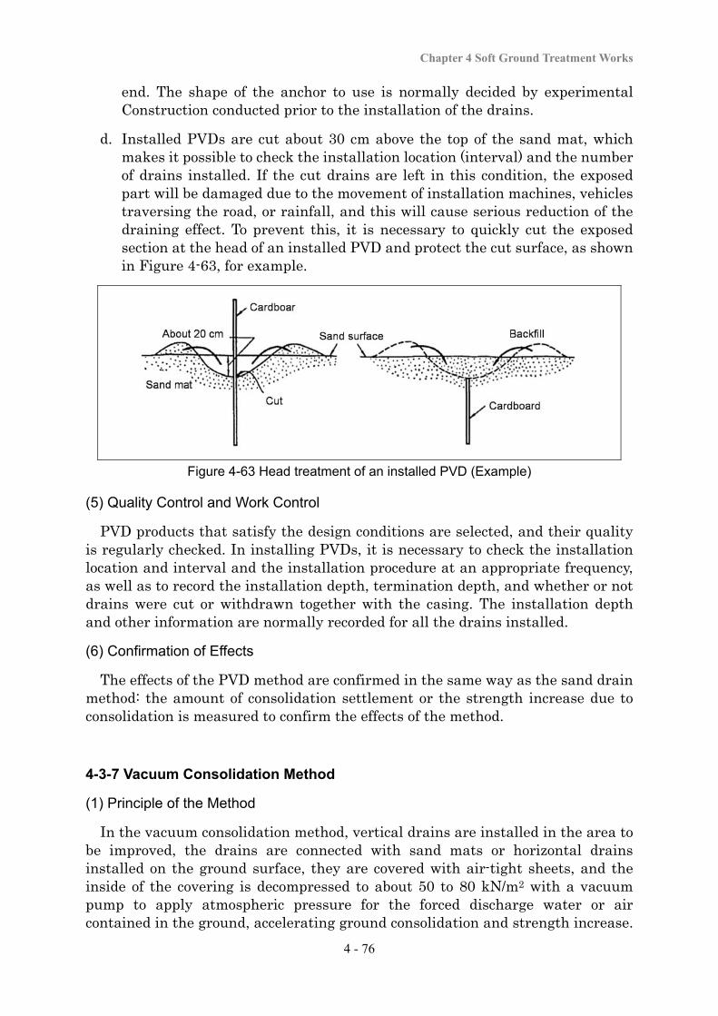
Chapter 4 Soft Ground Treatment Works
4 - 76
end. The shape of the anchor to use is normally decided by experimental Construction conducted prior to the installation of the drains.
d. Installed PVDs are cut about 30 cm above the top of the sand mat, which makes it possible to check the installation location (interval) and the number of drains installed. If the cut drains are left in this condition, the exposed part will be damaged due to the movement of installation machines, vehicles traversing the road, or rainfall, and this will cause serious reduction of the draining effect. To prevent this, it is necessary to quickly cut the exposed section at the head of an installed PVD and protect the cut surface, as shown in Figure 4-63, for example.
Figure 4-63 Head treatment of an installed PVD (Example)
(5) Quality Control and Work Control
PVD products that satisfy the design conditions are selected, and their quality is regularly checked. In installing PVDs, it is necessary to check the installation location and interval and the installation procedure at an appropriate frequency, as well as to record the installation depth, termination depth, and whether or not drains were cut or withdrawn together with the casing. The installation depth and other information are normally recorded for all the drains installed.
(6) Confirmation of Effects
The effects of the PVD method are confirmed in the same way as the sand drain method: the amount of consolidation settlement or the strength increase due to consolidation is measured to confirm the effects of the method.
4-3-7 Vacuum Consolidation Method
(1) Principle of the Method
In the vacuum consolidation method, vertical drains are installed in the area to be improved, the drains are connected with sand mats or horizontal drains installed on the ground surface, they are covered with air-tight sheets, and the inside of the covering is decompressed to about 50 to 80 kN/m2 with a vacuum pump to apply atmospheric pressure for the forced discharge water or air contained in the ground, accelerating ground consolidation and strength increase.
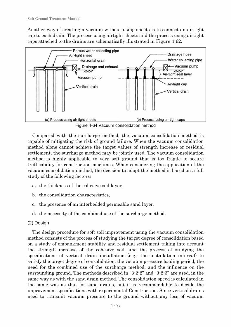
Soft Ground Treatment Manual
4 - 77
Another way of creating a vacuum without using sheets is to connect an airtight cap to each drain. The process using airtight sheets and the process using airtight caps attached to the drains are schematically illustrated in Figure 4-62.
(a) Process using air-tight sheets (b) Process using air-tight caps Figure 4-64 Vacuum consolidation method
Compared with the surcharge method, the vacuum consolidation method is capable of mitigating the risk of ground failure. When the vacuum consolidation method alone cannot achieve the target values of strength increase or residual settlement, the surcharge method may be jointly used. The vacuum consolidation method is highly applicable to very soft ground that is too fragile to secure trafficability for construction machines. When considering the application of the vacuum consolidation method, the decision to adopt the method is based on a full study of the following factors;
a. the thickness of the cohesive soil layer,
b. the consolidation characteristics,
c. the presence of an interbedded permeable sand layer,
d. the necessity of the combined use of the surcharge method.
(2) Design
The design procedure for soft soil improvement using the vacuum consolidation method consists of the process of studying the target degree of consolidation based on a study of embankment stability and residual settlement taking into account the strength increase of the cohesive soil, and the process of studying the specifications of vertical drain installation (e.g., the installation interval) to satisfy the target degree of consolidation, the vacuum pressure loading period, the need for the combined use of the surcharge method, and the influence on the surrounding ground. The methods described in “3-2-2” and “3-2-3” are used, in the same way as with the sand drain method. The consolidation speed is calculated in the same was as that for sand drains, but it is recommendable to decide the improvement specifications with experimental Construction. Since vertical drains need to transmit vacuum pressure to the ground without any loss of vacuum
Chapter 4 Soft Ground Treatment Works
4 - 78
pressure, they need to maintain high water permeability. The basic installation interval is 1 m. The interval may be set according to Figure 4-61.
(3) Execution
The vacuum consolidation method execution procedure is as follows.
a. Vertical drains are installed to the design improvement depth using installation equipment.
b. Porous water collecting pipes and horizontal drains are installed and connected to the heads of the vertical drains.
c. The entire improvement area is covered with airtight sheets. Alternatively, the drainage hoses are connected to the vertical drains and covered with a clay layer.
d. Atmospheric pressure is applied by decompressing the area within the airtight sheets or the drainage hoses with a vacuum pump (negative pressure of 50 to 80 kN/m2) to consolidate the soft soil.
e. Vacuum loading is completed when the prescribed consolidation settlement or strength increase is confirmed.
(4) Points of Design and Execution
Condition near the surface layer
If any protruding material, waste, rubble, or foreign matter that may damage the airtight sheets is mixed in the soil near the surface, or if there is an underground drainage ditch in the ground, it may be difficult to maintain air-tightness. If there is a fear that conditions like these exist, trial excavation is conducted in advance, and appropriate actions are taken, including the removal of waste.
Presence of permeable ground
When there is a deposit of a highly permeable gravel layer in the ground to which a vacuum is to be applied for consolidation, the vacuum consolidation system will continue to suction a large amount of groundwater, and this might make it difficult to maintain the design vacuum pressure. There can also be a fear of settlement of the surrounding ground due to a reduction in the groundwater level. In cases like these, it is necessary to study water cut-off measures (e.g., surrounding the work area with sheet piles).
Increase in the ground strength
According to the past application records, there are cases in which the cohesive force of the soil near the ground surface increased by about ∆ 20 kN/m2. If a greater strength increase is necessary, it is recommendable to study the combined use of the surcharge method. When airtight caps are used, caution is required, as
Soft Ground Treatment Manual
4 - 79
the strength increase of the sealing layer becomes a triangular distribution with 0 at the surface layer.
(5) Quality Control and Work Control
The quality of materials for drains, sheets, and drainage hoses used in the vacuum consolidation method is selected to satisfy the design conditions. The selected materials are periodically checked. In work control, the reliability of the connections between vertical drains or horizontal drains and the drainage hoses are confirmed, together with confirming that the internal soil has been decompressed to the target vacuum pressure and that the target amount of water is being released through the collecting and drainage pipes. For settlement management, ground monitoring is used to decide the vacuum loading time.
(6) Confirmation of Effects
The effects of the vacuum consolidation method are measured by checking the progress of the consolidation settlement or the acceleration of the strength increase. The confirmation procedure is the same as that specified in “4-3-3 Slow Banking Method”. If it is decided that the prescribed effects have not been obtained, the cause is investigated by checking the initial ground investigation results or work control records, and appropriate actions are studied (e.g., the vacuum pressure or extension of the vacuum pressure loading period).
4-3-8 Groundwater Lowering Method
(1) Principle of the Method
In the groundwater lowering method, the groundwater level in the ground is lowered and a load equivalent to the buoyancy that had worked on the ground is applied to the lower soft layer to accelerate consolidation and the soil strength increase. Since this method realizes acceleration of consolidation and the strength increase without directly applying the embankment load on the soft ground, it is capable of achieving its purpose in a highly stable condition without damaging soft ground where there is a fear of slip failure. The groundwater lowering processes normally used at soft ground sites are the well point system (Figure 4-65) and the deep well system. The well point system with a high head is also used to meet the need to penetrate to a greater depth for water drainage.
The groundwater lowering method is applied to ground in which sand layers are distributed in the upper part or middle part of a clay layer. However, it is also effective for types of cohesive soil ground in which many thin sand layers have developed in the horizontal direction. When constructing an embankment on peat soil, etc., where a large amount of settlement will occur, it is possible to utilize the buoyancy of the settled part of the embankment as an effective load by draining water from the sand mat and reducing the groundwater level. In applying the groundwater lowering method, it is necessary to make a full study of the thickness and permeability of the sand layer targeted for groundwater lowering, as well as
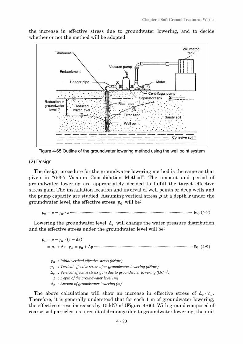
Chapter 4 Soft Ground Treatment Works
4 - 80
the increase in effective stress due to groundwater lowering, and to decide whether or not the method will be adopted.
Figure 4-65 Outline of the groundwater lowering method using the well point system
(2) Design
The design procedure for the groundwater lowering method is the same as that given in “6-3-7 Vacuum Consolidation Method”. The amount and period of groundwater lowering are appropriately decided to fulfill the target effective stress gain. The installation location and interval of well points or deep wells and the pump capacity are studied. Assuming vertical stress p at a depth z under the groundwater level, the effective stress will be:
⋅ ∙∙∙∙∙∙∙∙∙∙∙∙∙∙∙∙∙∙∙∙∙∙∙∙∙∙∙∙∙∙∙∙∙∙∙∙∙∙∙∙∙∙∙∙∙∙∙∙∙∙∙∙∙∙∙∙∙∙∙∙∙∙∙∙∙∙∙∙∙∙∙∙∙∙∙∙∙∙∙∙∙∙∙∙∙∙∙∙∙∙∙∙∙∙∙∙∙∙∙∙∙∙∙∙∙∙∙∙∙∙∙∙∙∙∙ Eq. 4-8
Lowering the groundwater level ∆ will change the water pressure distribution, and the effective stress under the groundwater level will be:
⋅ ∆
∆ ⋅ ∆p ∙∙∙∙∙∙∙∙∙∙∙∙∙∙∙∙∙∙∙∙∙∙∙∙∙∙∙∙∙∙∙∙∙∙∙∙∙∙∙∙∙∙∙∙∙∙∙∙∙∙∙∙∙∙∙∙∙∙∙∙∙∙∙∙∙∙∙∙∙∙∙∙∙∙∙∙∙∙∙∙∙∙∙∙∙∙∙∙∙∙∙∙∙ Eq. 4-9
: Initial vertical effective stress (kN/m2)
: Vertical effective stress after groundwater lowering (kN/m2)
∆ : Vertical effective stress gain due to groundwater lowering (kN/m2)
z : Depth of the groundwater level (m)
∆ : Amount of groundwater lowering (m)
The above calculations will show an increase in effective stress of ∆ ∙ . Therefore, it is generally understood that for each 1 m of groundwater lowering, the effective stress increases by 10 kN/m2 (Figure 4-66). With ground composed of coarse soil particles, as a result of drainage due to groundwater lowering, the unit
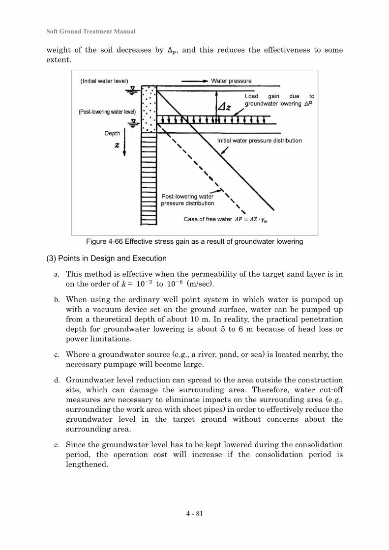
Soft Ground Treatment Manual
4 - 81
weight of the soil decreases by ∆ , and this reduces the effectiveness to some extent.
Figure 4-66 Effective stress gain as a result of groundwater lowering
(3) Points in Design and Execution
a. This method is effective when the permeability of the target sand layer is in on the order of k = 10 to 10 (m/sec).
b. When using the ordinary well point system in which water is pumped up with a vacuum device set on the ground surface, water can be pumped up from a theoretical depth of about 10 m. In reality, the practical penetration depth for groundwater lowering is about 5 to 6 m because of head loss or power limitations.
c. Where a groundwater source (e.g., a river, pond, or sea) is located nearby, the necessary pumpage will become large.
d. Groundwater level reduction can spread to the area outside the construction site, which can damage the surrounding area. Therefore, water cut-off measures are necessary to eliminate impacts on the surrounding area (e.g., surrounding the work area with sheet pipes) in order to effectively reduce the groundwater level in the target ground without concerns about the surrounding area.
e. Since the groundwater level has to be kept lowered during the consolidation period, the operation cost will increase if the consolidation period is lengthened.
Chapter 4 Soft Ground Treatment Works
4 - 82
(4) Quality Control and Work Control
When applying the groundwater lowering method, in order to maintain the design groundwater level for a certain duration of time, it is necessary to confirm the capacity of the drainage pump and vacuum pump in advance, and to confirm the installation position and interval of well points or deep wells. Daily management items include the groundwater level and the amount of drainage. Settlement management is conducted with ground monitoring in order to decide the period of groundwater lowering.
(5) Confirmation of Effects
The effects of the groundwater lowering method are normally confirmed by the acceleration of consolidation settlement or the acceleration of the strength increase by consolidation. The confirmation procedure is the same as that described in “4-3-3 Slow Banking Method”. If the prescribed effects have not been achieved, the causes are investigated by confirming the initial ground investigation results and work control records, and appropriate actions are taken, including changing the period of groundwater lowering.
Soft Ground Treatment Manual
4 - 83
4-4 Compaction Methods
The compaction method is largely divided into vibratory compaction and static compaction. The sand compaction pile method (or gravel compaction pile method, if crushed stone is used instead of sand) is the most often used vibratory compaction method. Other methods include rod compaction, vibro-tamping, vibro-floatation, and falling weight compaction. On the other hand, in the static compaction method, soils are improved by forming sand piles or injecting filling materials through static injection without providing any dynamic energy (e.g., vibration or tamping). This method was developed as a result of the growing difficulty of applying the vibratory compaction method in urban areas, locations close to houses, and narrow spaces. Static compaction methods include the static compacted sand pile method and the static pressure fit compaction method. In recent years, the number of cases in which the impact of vibration during the work on the surrounding environment has become a serious problem has been increasing. When it is known during the planning stage that the work could cause a situation like this, it is necessary to study the selection of the static compaction method.
Among compaction methods, processes of forming sand piles in the soil (i.e., the sand compaction pile method as a vibratory compaction method and the static compacted sand pile method as a static compaction method) are applicable in a wide variety of conditions ranging from the compaction of loose sandy ground to stability and settlement control for cohesive soil ground.
In designing soft soil improvement using the compaction method for sandy soil ground, the area of improvement and the degree of improvement are decided from the viewpoint of the performance requirements of the structure. As N-values are often used to study the bearing capacity or liquefaction of sandy soil ground, the improvement specifications (including the sand pile diameter or installation interval) are decided based on the N-values of the ground before and after improvement according to the design procedure for soft soil improvement using each method. For the purpose of the design to prevent liquefaction of the ground under the embankment, the safety factor against circular slips or the amount of deformation in the event of a major earthquake can be calculated by using an arbitrarily assumed N-value for the improved ground and carrying out an analysis using the technique described in 5-6. The next steps include calculating the resistance against liquefaction factor from the N-value of the ground after improvement, from this , calculating the excess pore water pressure that would occur during an earthquake, and deciding the safety factor against circular slips. Lastly, the specifications of the method are set from the target N-value after improvement. The process of creating compacted sand piles in cohesive soil ground is employed in order to use the sand piles to distribute load stress and to accelerate drainage for controlling the stability and settlement of cohesive soil ground. It is necessary to make a full advance study of the impacts of vibration, noise, and displacement during execution of the compaction method as described in “4-2-3 Applicability of Each Method”.
Chapter 4 Soft Ground Treatment Works
4 - 84
4-4-1 Sand Compaction Pile Method
(1) Principle of the Method
In the sand compaction pile (SCP) method, steel pipes are drilled into the ground, sand is inserted into the pipes, and sand piles are created by vibration compaction in the ground. This method features applicability to both sandy soil ground and cohesive soil ground, although with different improvement principles. It handles sandy soil ground with vibration to compact the surrounding ground and handles cohesive soil ground with sand piles to distribute stress and accelerate drainage. The major improvement purposes of the SCP method include increasing the bearing capacity, reducing compression settlement, preventing liquefaction, and increasing lateral resistance for loose sandy soil ground; and increasing bearing capacity, accelerating consolidation, reducing consolidation settlement, and increasing lateral resistance for cohesive soil ground.
Crushed stone or gravel may be used instead of sand when quality sand cannot be easily obtained or the improved sand piles require large strength. These processes, called the gravel compaction piling method and crushed stone compaction piling method, respectively, share the same improvement principles as the SCP method. In recent years, slag, recycled crushed stone, and other recycled materials are actively used depending on the purpose of use.
Since the improvement principles and design procedures differ between the application of the method to sandy soil ground and to cohesive soil ground, the descriptions below are given separately according to the applicable ground type.
Sandy soil ground
The application principles for sandy soil ground are a combination of the vibration-based compaction effect and the compaction effect due to sand injection. The plan is to reduce the void ratio of sandy soil ground in order to increase density and shear strength.
Cohesive soil ground
When many sand piles are driven into soft cohesive soil ground, the ground becomes a composite ground composed of sand piles and cohesive soil. When a load is applied on this composite ground, the burden load is supported more by the sand piles than by the cohesive soil, as sand is more rigid than cohesive soil. As a result, the stress supported by the cohesive soil decreases and reduces the amount of consolidation settlement. Moreover, because sand piles are constructed with shear strength greater than that of the original ground, the strength increase of the soil increases according to the amount of cohesive earth replaced by sand piles. In addition, a consolidation acceleration effect is also obtained, in the same way as with sand drains.
When a loose sand layer is deposited on a cohesive soil layer and consolidation of the cohesive soil layer needs to be accelerated with the sand layer, the use of
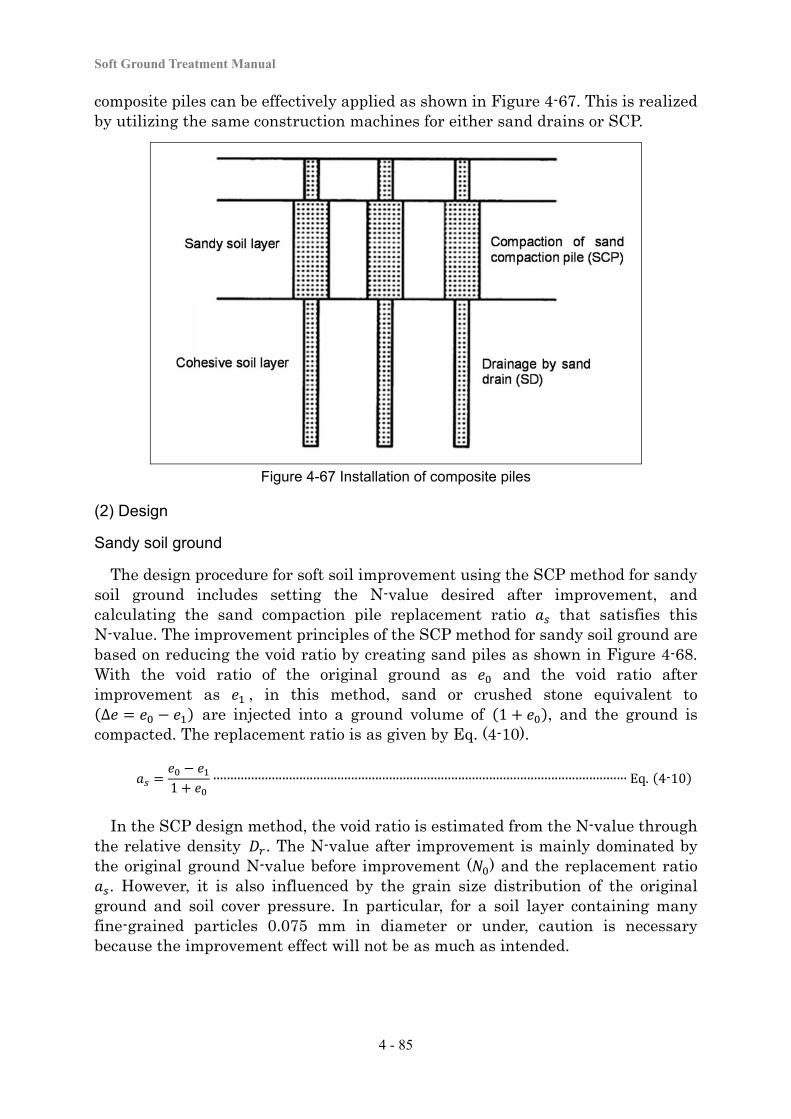
Soft Ground Treatment Manual
4 - 85
composite piles can be effectively applied as shown in Figure 4-67. This is realized by utilizing the same construction machines for either sand drains or SCP.
Figure 4-67 Installation of composite piles
(2) Design
Sandy soil ground
The design procedure for soft soil improvement using the SCP method for sandy soil ground includes setting the N-value desired after improvement, and calculating the sand compaction pile replacement ratio that satisfies this N-value. The improvement principles of the SCP method for sandy soil ground are based on reducing the void ratio by creating sand piles as shown in Figure 4-68. With the void ratio of the original ground as and the void ratio after improvement as , in this method, sand or crushed stone equivalent to ∆ are injected into a ground volume of 1 , and the ground is
compacted. The replacement ratio is as given by Eq. (4-10).
1∙∙∙∙∙∙∙∙∙∙∙∙∙∙∙∙∙∙∙∙∙∙∙∙∙∙∙∙∙∙∙∙∙∙∙∙∙∙∙∙∙∙∙∙∙∙∙∙∙∙∙∙∙∙∙∙∙∙∙∙∙∙∙∙∙∙∙∙∙∙∙∙∙∙∙∙∙∙∙∙∙∙∙∙∙∙∙∙∙∙∙∙∙∙∙∙∙∙∙∙∙∙∙∙∙∙∙∙∙∙∙∙∙∙∙∙∙∙∙∙ Eq. 4-10
In the SCP design method, the void ratio is estimated from the N-value through the relative density . The N-value after improvement is mainly dominated by the original ground N-value before improvement ( ) and the replacement ratio
. However, it is also influenced by the grain size distribution of the original ground and soil cover pressure. In particular, for a soil layer containing many fine-grained particles 0.075 mm in diameter or under, caution is necessary because the improvement effect will not be as much as intended.
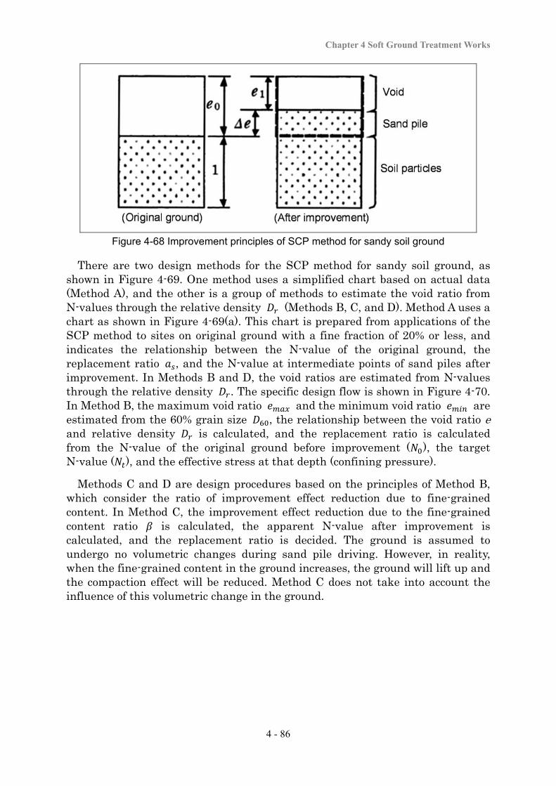
Chapter 4 Soft Ground Treatment Works
4 - 86
Figure 4-68 Improvement principles of SCP method for sandy soil ground
There are two design methods for the SCP method for sandy soil ground, as shown in Figure 4-69. One method uses a simplified chart based on actual data (Method A), and the other is a group of methods to estimate the void ratio from N-values through the relative density (Methods B, C, and D). Method A uses a chart as shown in Figure 4-69(a). This chart is prepared from applications of the SCP method to sites on original ground with a fine fraction of 20% or less, and indicates the relationship between the N-value of the original ground, the replacement ratio , and the N-value at intermediate points of sand piles after improvement. In Methods B and D, the void ratios are estimated from N-values through the relative density . The specific design flow is shown in Figure 4-70. In Method B, the maximum void ratio and the minimum void ratio are estimated from the 60% grain size , the relationship between the void ratio e and relative density is calculated, and the replacement ratio is calculated from the N-value of the original ground before improvement ( ), the target N-value ( ), and the effective stress at that depth (confining pressure).
Methods C and D are design procedures based on the principles of Method B, which consider the ratio of improvement effect reduction due to fine-grained content. In Method C, the improvement effect reduction due to the fine-grained content ratio is calculated, the apparent N-value after improvement is calculated, and the replacement ratio is decided. The ground is assumed to undergo no volumetric changes during sand pile driving. However, in reality, when the fine-grained content in the ground increases, the ground will lift up and the compaction effect will be reduced. Method C does not take into account the influence of this volumetric change in the ground.
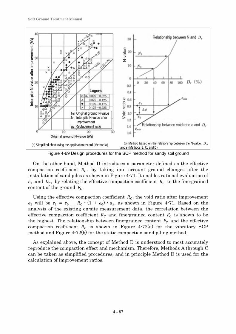
Soft Ground Treatment Manual
4 - 87
(a) Simplified chart using the application record (Method A) (b) Method based on the relationship between the N-value, , and e (Methods B, C, and D)
Figure 4-69 Design procedures for the SCP method for sandy soil ground
On the other hand, Method D introduces a parameter defined as the effective compaction coefficient , by taking into account ground changes after the installation of sand piles as shown in Figure 4-71. It enables rational evaluation of
and by relating the effective compaction coefficient to the fine-grained content of the ground .
Using the effective compaction coefficient , the void ratio after improvement will be = ・(1 + )・ , as shown in Figure 4-71. Based on the
analysis of the existing on-site measurement data, the correlation between the effective compaction coefficient and fine-grained content is shown to be the highest. The relationship between fine-grained content and the effective compaction coefficient is shown in Figure 4-72(a) for the vibratory SCP method and Figure 4-72(b) for the static compaction sand piling method.
As explained above, the concept of Method D is understood to most accurately reproduce the compaction effect and mechanism. Therefore, Methods A through C can be taken as simplified procedures, and in principle Method D is used for the calculation of improvement ratios.

Chapter 4 Soft Ground Treatment Works
4 - 88
Figure 4-70 Calculation flow of the design procedure for the SCP method for sandy soil ground
Method C
Set the N-value of the original ground and target N-value after improvement
Method B Method D
Calculate and from the fine-grained content
(%) using the following equations:
emax = 0.02 Fc + 1.0
emin = 0.008 Fc + 0.6
Set the maximum void ratio and minimum void
ratio .
Calculate and from the original ground grading ( or ). ( is the diameter of the most frequent particles.)
Calculate and from the fine-grained content
(%) using the following equations:
emax = 0.02Fc + 1.0
emin = 0.008Fc + 0.6
Calculate relative density and from the
original ground N-value and confining pressure ′ (kN/m
2).
D
r0 = 21⋅ / 0.7 ’/98
emax
Calculate the initial void ratio from the N-value of the original ground and relative density .
Read the equivalent to the original ground N-value
through the confining pressure from the relationship between the N-value, confining pressure, relative density , and void ratio e.
Calculate relative density and from the
original ground N-value and confining pressure ′
(kN/m2) and corrected
N-value increment ∆ due to fine-grained content.
Dr0
= 21 ⋅. / .
e0=e
max-
Where ∆ is:
Fc (%) ∆
0∼5 0 5∼10 1.2(F
c-5)
10∼20 6+0.2(Fc-10)
20∼ 8+0.1(Fc-20)
Calculate the reduction factor ′ relative to the increased N-value due to fine-grained content.
=1.05-0.51 log Fc
Calculate the coefficient related to the reduction of the compaction effect due to fine-grained content.
Calculate the effective compaction coefficient relative to the increased N-value due to fine-grained content.
Rc=1.05-0.46 log F
c
Calculate the apparent N-value ′ assuming no fine-grained content taking into account the reduction factor . Then, calculate as the void ratio corresponding to this ′.
N1 '= N0 + (N1-N0)/)
Dr1
= 21⋅ ′/ 0.7
e1 = e
max-
Calculate the void ratio after improvement from the N-value after improvement
and relative density .
Read equivalent to the N-value after improvement
through the confining pressure from the relationship between the N-value, confining pressure, relative density , and void ratio e.
Calculate the relative density and from the target
N-value after improvement , confining pressure ′
(kN/m2), and ∆ .
Dr1
= 21⋅. / .
e1=e
max-
Calculate the replacement ratio from the following equation:
as =
Calculate the replacement ratio from the void ratio before improvement and void ratio after improvement
.
Calculate the replacement ratio from the following equation: a
s =
Calculate the replacement ratio taking into account the effective compaction coefficient.
as =
∆ =
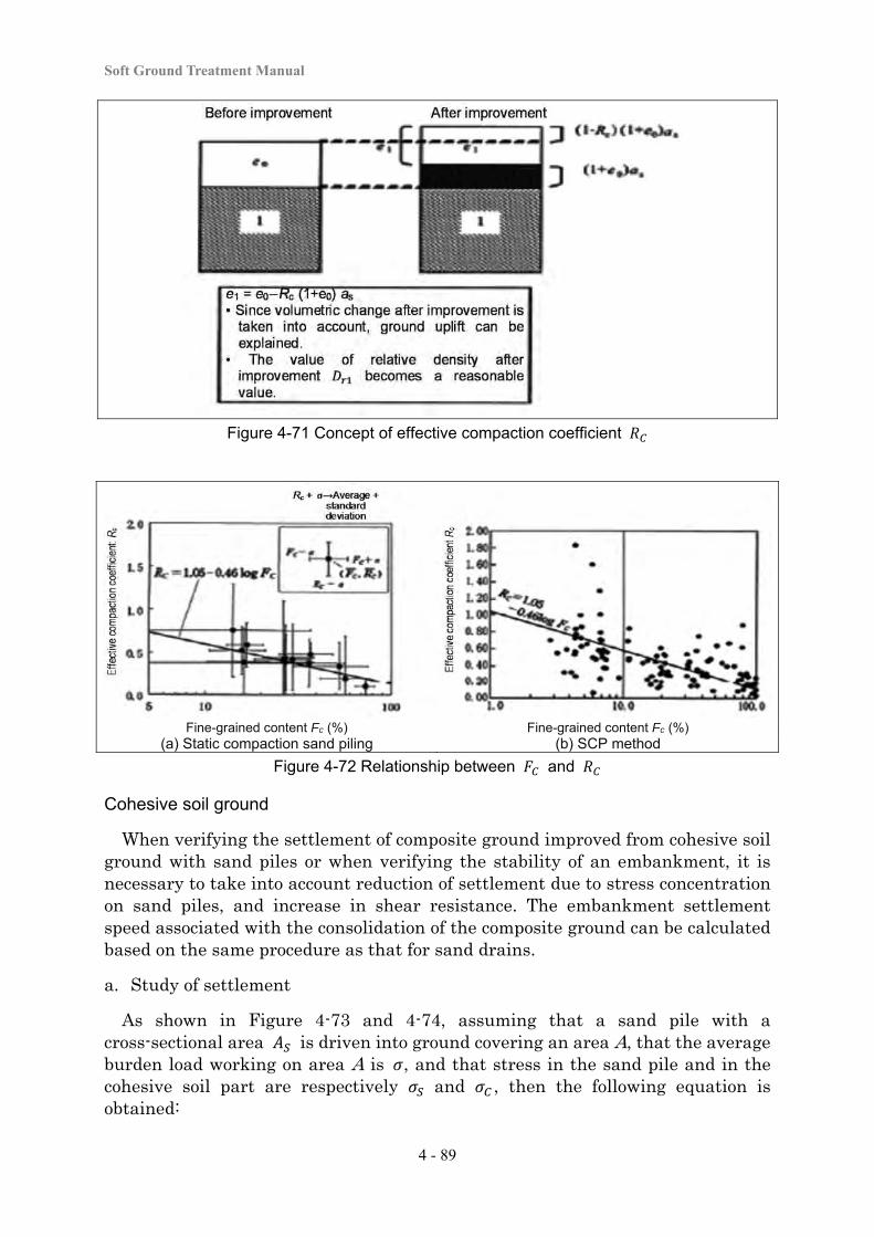
Soft Ground Treatment Manual
4 - 89
Figure 4-71 Concept of effective compaction coefficient
Fine-grained content Fc (%) Fine-grained content Fc (%) (a) Static compaction sand piling (b) SCP method
Figure 4-72 Relationship between and
Cohesive soil ground
When verifying the settlement of composite ground improved from cohesive soil ground with sand piles or when verifying the stability of an embankment, it is necessary to take into account reduction of settlement due to stress concentration on sand piles, and increase in shear resistance. The embankment settlement speed associated with the consolidation of the composite ground can be calculated based on the same procedure as that for sand drains.
a. Study of settlement
As shown in Figure 4-73 and 4-74, assuming that a sand pile with a cross-sectional area is driven into ground covering an area A, that the average burden load working on area A is , and that stress in the sand pile and in the cohesive soil part are respectively and , then the following equation is obtained:
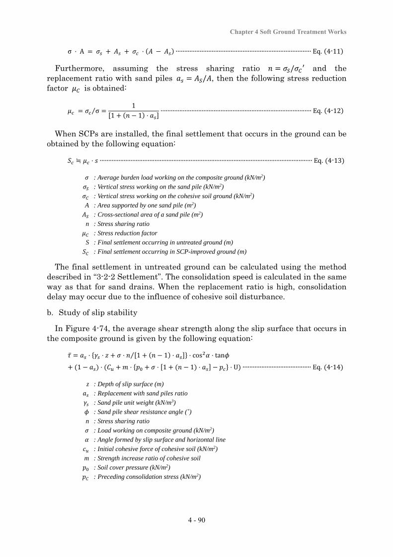
Chapter 4 Soft Ground Treatment Works
4 - 90
σ ⋅ Α ⋅ ∙∙∙∙∙∙∙∙∙∙∙∙∙∙∙∙∙∙∙∙∙∙∙∙∙∙∙∙∙∙∙∙∙∙∙∙∙∙∙∙∙∙∙∙∙∙∙∙∙∙∙∙∙∙∙∙∙∙∙∙∙∙∙∙∙∙∙∙∙∙∙∙∙∙∙∙∙∙∙ Eq. 4-11
Furthermore, assuming the stress sharing ratio / ′ and the replacement ratio with sand piles / , then the following stress reduction factor is obtained:
σ⁄1
1 1 ⋅∙∙∙∙∙∙∙∙∙∙∙∙∙∙∙∙∙∙∙∙∙∙∙∙∙∙∙∙∙∙∙∙∙∙∙∙∙∙∙∙∙∙∙∙∙∙∙∙∙∙∙∙∙∙∙∙∙∙∙∙∙∙∙∙∙∙∙∙∙∙∙∙∙∙∙∙∙∙∙∙∙∙∙∙∙∙∙∙ Eq. 4-12
When SCPs are installed, the final settlement that occurs in the ground can be obtained by the following equation:
≒ ⋅ ∙∙∙∙∙∙∙∙∙∙∙∙∙∙∙∙∙∙∙∙∙∙∙∙∙∙∙∙∙∙∙∙∙∙∙∙∙∙∙∙∙∙∙∙∙∙∙∙∙∙∙∙∙∙∙∙∙∙∙∙∙∙∙∙∙∙∙∙∙∙∙∙∙∙∙∙∙∙∙∙∙∙∙∙∙∙∙∙∙∙∙∙∙∙∙∙∙∙∙∙∙∙∙∙∙∙∙∙∙∙∙∙∙∙∙∙∙∙∙∙∙∙∙∙ Eq. 4-13
: Average burden load working on the composite ground (kN/m2)
: Vertical stress working on the sand pile (kN/m2)
: Vertical stress working on the cohesive soil ground (kN/m2)
A : Area supported by one sand pile (m2)
: Cross-sectional area of a sand pile (m2)
n : Stress sharing ratio
: Stress reduction factor
S : Final settlement occurring in untreated ground (m)
: Final settlement occurring in SCP-improved ground (m)
The final settlement in untreated ground can be calculated using the method described in “3-2-2 Settlement”. The consolidation speed is calculated in the same way as that for sand drains. When the replacement ratio is high, consolidation delay may occur due to the influence of cohesive soil disturbance.
b. Study of slip stability
In Figure 4-74, the average shear strength along the slip surface that occurs in the composite ground is given by the following equation:
⋅ ⋅ ⋅ 1 1 ⋅⁄ ⋅ cos ⋅ tan
1 ⋅ ⋅ ⋅ 1 1 ⋅ ⋅ U ∙∙∙∙∙∙∙∙∙∙∙∙∙∙∙∙∙∙∙∙∙∙∙∙∙∙∙∙∙∙∙∙∙∙∙∙∙∙∙∙ Eq. 4-14
z : Depth of slip surface (m)
: Replacement with sand piles ratio
: Sand pile unit weight (kN/m3)
: Sand pile shear resistance angle (˚)
n : Stress sharing ratio
: Load working on composite ground (kN/m2)
: Angle formed by slip surface and horizontal line
: Initial cohesive force of cohesive soil (kN/m2)
m : Strength increase ratio of cohesive soil
: Soil cover pressure (kN/m2)
: Preceding consolidation stress (kN/m2)
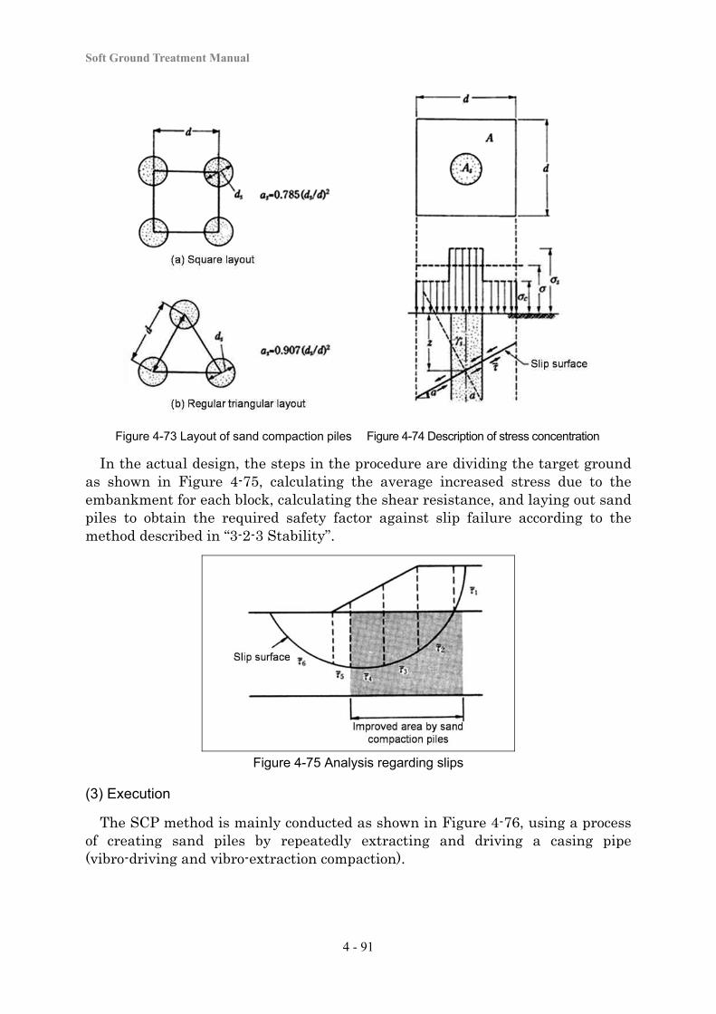
Soft Ground Treatment Manual
4 - 91
Figure 4-73 Layout of sand compaction piles Figure 4-74 Description of stress concentration
In the actual design, the steps in the procedure are dividing the target ground as shown in Figure 4-75, calculating the average increased stress due to the embankment for each block, calculating the shear resistance, and laying out sand piles to obtain the required safety factor against slip failure according to the method described in “3-2-3 Stability”.
Figure 4-75 Analysis regarding slips
(3) Execution
The SCP method is mainly conducted as shown in Figure 4-76, using a process of creating sand piles by repeatedly extracting and driving a casing pipe (vibro-driving and vibro-extraction compaction).
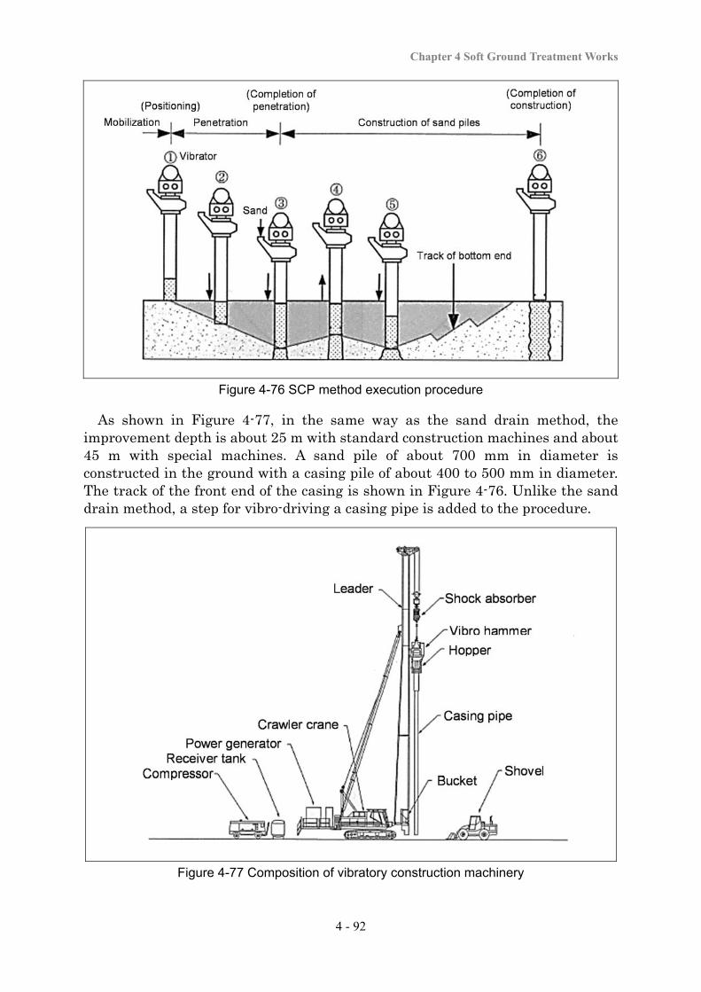
Chapter 4 Soft Ground Treatment Works
4 - 92
Figure 4-76 SCP method execution procedure
As shown in Figure 4-77, in the same way as the sand drain method, the improvement depth is about 25 m with standard construction machines and about 45 m with special machines. A sand pile of about 700 mm in diameter is constructed in the ground with a casing pile of about 400 to 500 mm in diameter. The track of the front end of the casing is shown in Figure 4-76. Unlike the sand drain method, a step for vibro-driving a casing pipe is added to the procedure.
Figure 4-77 Composition of vibratory construction machinery
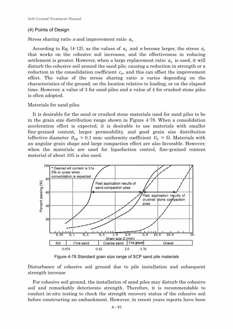
Soft Ground Treatment Manual
4 - 93
(4) Points of Design
Stress sharing ratio n and improvement ratio
According to Eq. (4-12), as the values of and n become larger, the stress that works on the cohesive soil increases, and the effectiveness in reducing settlement is greater. However, when a large replacement ratio is used, it will disturb the cohesive soil around the sand pile, causing a reduction in strength or a reduction in the consolidation coefficient , and this can offset the improvement effect. The value of the stress sharing ratio n varies depending on the characteristics of the ground, on the location relative to loading, or on the elapsed time. However, a value of 3 for sand piles and a value of 4 for crushed stone piles is often adopted.
Materials for sand piles
It is desirable for the sand or crushed stone materials used for sand piles to be in the grain size distribution range shown in Figure 4-78. When a consolidation acceleration effect is expected, it is desirable to use materials with smaller fine-grained content, larger permeability, and good grain size distribution (effective diameter > 0.1 mm; uniformity coefficient > 5). Materials with an angular grain shape and large compaction effect are also favorable. However, when the materials are used for liquefaction control, fine-grained content material of about 105 is also used.
Figure 4-78 Standard grain size range of SCP sand pile materials
Disturbance of cohesive soil ground due to pile installation and subsequent strength increase
For cohesive soil ground, the installation of sand piles may disturb the cohesive soil and remarkably deteriorate strength. Therefore, it is recommendable to conduct in-situ testing to check the strength recovery status of the cohesive soil before constructing an embankment. However, in recent years reports have been
Chapter 4 Soft Ground Treatment Works
4 - 94
published on proactively applying the subsequent strength recovery and the ensuing strength increase beyond that of the original ground into the design. For a cohesive soil that is not particularly sensitive, the excess pore water pressure that occurs in the ground around the sand piles immediately after pile installation disperses and increases the strength of the cohesive soil with consolidation. Proactively incorporating this process into the design will be able to realize a reduction in the amount of preloading. However, when actually considering this in the design, it is necessary to take into account the elapsed time after installation.
Evaluation of liquefaction resistance in sandy soil ground
For sandy soil ground compacted with SCPs, evaluation of liquefaction resistance is generally conducted using the N-value between sand pilings. Another approach to this evaluation is to consider the N-value of the core of the sand pile with the ground assumed to be composite ground. It is possible to consider effectiveness from the results of implementing a detailed investigation.
(5) Points in execution
a. Carefully manage the sand pile installation location (interval) and depth.
b. Confirm whether or not the installed sand piles have been formed with the prescribed diameter by checking the relationship between the input sand amount and the finished depth (for each depth).
c. For cohesive soil ground, since the ground strength can be seriously degraded by disturbance of the cohesive soil due to the installation of sand piles, it is recommendable to conduct in-situ testing and check the status of strength recovery of the cohesive soil prior to constructing an embankment.
d. Caution is necessary as sand boil can occur along the sand pile when the pile is driven into an artesian aquifer.
e. Full consideration is necessary regarding the possible impact of vibration or noise on the surrounding environment.
f. Full consideration is necessary regarding impacts on the surrounding ground (lateral displacement or uplift), and appropriate actions are taken (including the excavation of a trench for physical separation) whenever it is considered to be necessary. Particularly care is required when a structure (e.g., a house, buried matter, or a water channel) is located nearby.
g. It is necessary to pay sufficient attention to securing trafficability for construction machines in the same way as with sand drains.
(6) Quality Control and Work Control
When selecting materials for the SCP method, it is necessary to find materials with a grain size distribution that satisfies the prescribed range, and to regularly conduct management testing by sampling. In applying the SCP method, it is essential to check the installation location, interval, and procedure at an appropriate frequency; to measure the installation depth, the input sand amount,
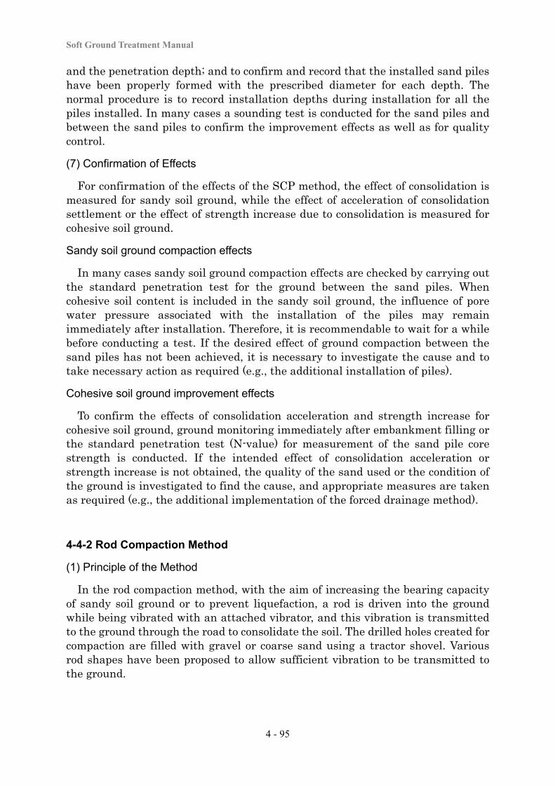
Soft Ground Treatment Manual
4 - 95
and the penetration depth; and to confirm and record that the installed sand piles have been properly formed with the prescribed diameter for each depth. The normal procedure is to record installation depths during installation for all the piles installed. In many cases a sounding test is conducted for the sand piles and between the sand piles to confirm the improvement effects as well as for quality control.
(7) Confirmation of Effects
For confirmation of the effects of the SCP method, the effect of consolidation is measured for sandy soil ground, while the effect of acceleration of consolidation settlement or the effect of strength increase due to consolidation is measured for cohesive soil ground.
Sandy soil ground compaction effects
In many cases sandy soil ground compaction effects are checked by carrying out the standard penetration test for the ground between the sand piles. When cohesive soil content is included in the sandy soil ground, the influence of pore water pressure associated with the installation of the piles may remain immediately after installation. Therefore, it is recommendable to wait for a while before conducting a test. If the desired effect of ground compaction between the sand piles has not been achieved, it is necessary to investigate the cause and to take necessary action as required (e.g., the additional installation of piles).
Cohesive soil ground improvement effects
To confirm the effects of consolidation acceleration and strength increase for cohesive soil ground, ground monitoring immediately after embankment filling or the standard penetration test (N-value) for measurement of the sand pile core strength is conducted. If the intended effect of consolidation acceleration or strength increase is not obtained, the quality of the sand used or the condition of the ground is investigated to find the cause, and appropriate measures are taken as required (e.g., the additional implementation of the forced drainage method).
4-4-2 Rod Compaction Method
(1) Principle of the Method
In the rod compaction method, with the aim of increasing the bearing capacity of sandy soil ground or to prevent liquefaction, a rod is driven into the ground while being vibrated with an attached vibrator, and this vibration is transmitted to the ground through the road to consolidate the soil. The drilled holes created for compaction are filled with gravel or coarse sand using a tractor shovel. Various rod shapes have been proposed to allow sufficient vibration to be transmitted to the ground.
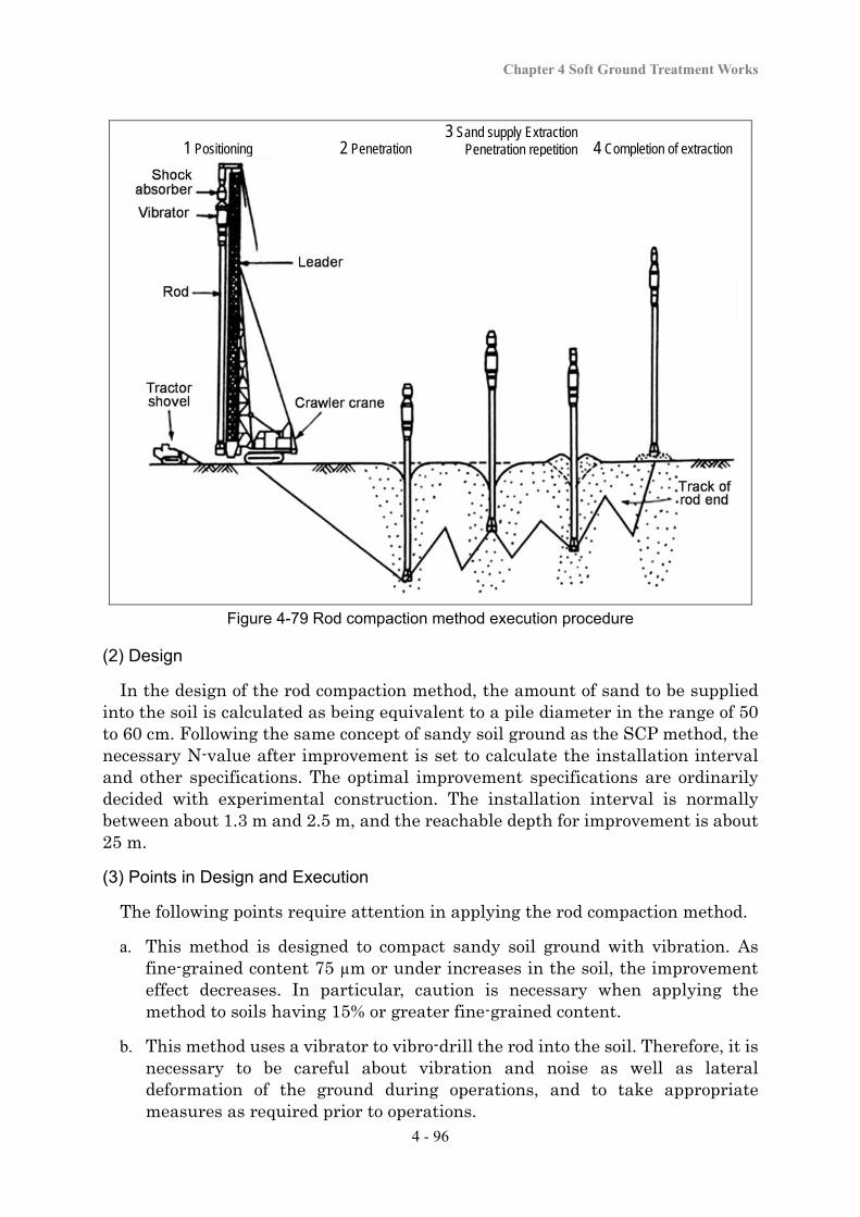
Chapter 4 Soft Ground Treatment Works
4 - 96
1 Positioning 2 Penetration 3 Sand supply Extraction
Penetration repetition 4 Completion of extraction
Figure 4-79 Rod compaction method execution procedure
(2) Design
In the design of the rod compaction method, the amount of sand to be supplied into the soil is calculated as being equivalent to a pile diameter in the range of 50 to 60 cm. Following the same concept of sandy soil ground as the SCP method, the necessary N-value after improvement is set to calculate the installation interval and other specifications. The optimal improvement specifications are ordinarily decided with experimental construction. The installation interval is normally between about 1.3 m and 2.5 m, and the reachable depth for improvement is about 25 m.
(3) Points in Design and Execution
The following points require attention in applying the rod compaction method.
a. This method is designed to compact sandy soil ground with vibration. As fine-grained content 75 µm or under increases in the soil, the improvement effect decreases. In particular, caution is necessary when applying the method to soils having 15% or greater fine-grained content.
b. This method uses a vibrator to vibro-drill the rod into the soil. Therefore, it is necessary to be careful about vibration and noise as well as lateral deformation of the ground during operations, and to take appropriate measures as required prior to operations.
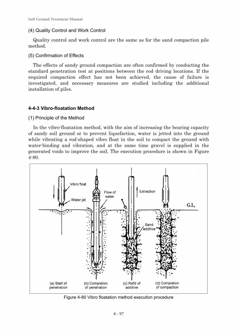
Soft Ground Treatment Manual
4 - 97
(4) Quality Control and Work Control
Quality control and work control are the same as for the sand compaction pile method.
(5) Confirmation of Effects
The effects of sandy ground compaction are often confirmed by conducting the standard penetration test at positions between the rod driving locations. If the required compaction effect has not been achieved, the cause of failure is investigated, and necessary measures are studied including the additional installation of piles.
4-4-3 Vibro-floatation Method
(1) Principle of the Method
In the vibro-floatation method, with the aim of increasing the bearing capacity of sandy soil ground or to prevent liquefaction, water is jetted into the ground while vibrating a rod-shaped vibro float in the soil to compact the ground with water-binding and vibration, and at the same time gravel is supplied in the generated voids to improve the soil. The execution procedure is shown in Figure 4-80.
Figure 4-80 Vibro floatation method execution procedure
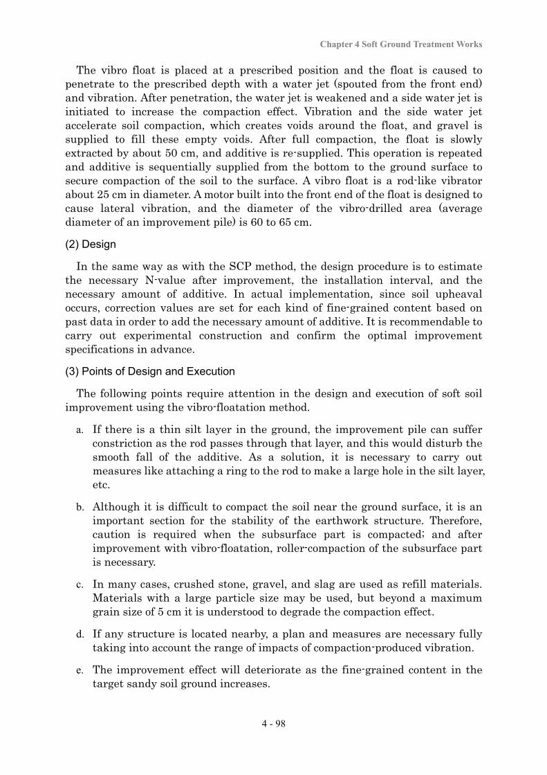
Chapter 4 Soft Ground Treatment Works
4 - 98
The vibro float is placed at a prescribed position and the float is caused to penetrate to the prescribed depth with a water jet (spouted from the front end) and vibration. After penetration, the water jet is weakened and a side water jet is initiated to increase the compaction effect. Vibration and the side water jet accelerate soil compaction, which creates voids around the float, and gravel is supplied to fill these empty voids. After full compaction, the float is slowly extracted by about 50 cm, and additive is re-supplied. This operation is repeated and additive is sequentially supplied from the bottom to the ground surface to secure compaction of the soil to the surface. A vibro float is a rod-like vibrator about 25 cm in diameter. A motor built into the front end of the float is designed to cause lateral vibration, and the diameter of the vibro-drilled area (average diameter of an improvement pile) is 60 to 65 cm.
(2) Design
In the same way as with the SCP method, the design procedure is to estimate the necessary N-value after improvement, the installation interval, and the necessary amount of additive. In actual implementation, since soil upheaval occurs, correction values are set for each kind of fine-grained content based on past data in order to add the necessary amount of additive. It is recommendable to carry out experimental construction and confirm the optimal improvement specifications in advance.
(3) Points of Design and Execution
The following points require attention in the design and execution of soft soil improvement using the vibro-floatation method.
a. If there is a thin silt layer in the ground, the improvement pile can suffer constriction as the rod passes through that layer, and this would disturb the smooth fall of the additive. As a solution, it is necessary to carry out measures like attaching a ring to the rod to make a large hole in the silt layer, etc.
b. Although it is difficult to compact the soil near the ground surface, it is an important section for the stability of the earthwork structure. Therefore, caution is required when the subsurface part is compacted; and after improvement with vibro-floatation, roller-compaction of the subsurface part is necessary.
c. In many cases, crushed stone, gravel, and slag are used as refill materials. Materials with a large particle size may be used, but beyond a maximum grain size of 5 cm it is understood to degrade the compaction effect.
d. If any structure is located nearby, a plan and measures are necessary fully taking into account the range of impacts of compaction-produced vibration.
e. The improvement effect will deteriorate as the fine-grained content in the target sandy soil ground increases.

Soft Ground Treatment Manual
4 - 99
f. Soft soil improvement using this method is feasible down to a depth of 18 m, and for a soil with N-value of about 20.
(4) Quality Control and Work Control
Quality control and work control are the same as for the sand compaction pile method.
(5) Confirmation of Effects
The improvement effects for sandy soil ground are checked according to the compaction status. The confirmation procedure is the same as that in “4-4-2 Rod Compaction Method”. If the prescribed effect has not been achieved, the cause is investigated, and appropriate measures are studied (e.g., the additional installation of piles).
4-4-4 Vibro-tamper Method
(1) Principle of the Method
In the vibro-tamper method, with the aim of increasing the bearing capacity of sandy soil ground or to prevent liquefaction, soil density is increased with the combined use of a powerful vibrator and tamper, and the ground is compacted down to 3 to 5 m from the ground surface. When vibratory compaction (e.g., the SCP method or rod compaction method) is used, sufficient compaction may not be realized because of a small confining pressure in the surface section, and the vibro-tamper method is often used as an auxiliary method in these cases. The main machines used to execute this method are crawler cranes, and particularly those with a function of hoisting a vibrator-equipped tamper (built-in type). As this type of crane has excellent mobility, it is applicable to a wide-area, large-scale project site as well as a narrow project site. Another type of this method is a tractor-type meant for rolling embankments.
(2) Design
In the design of the vibro-tamper method, the necessary N-value or density gain after improvement is estimated, and the vibration energy (number of passes and tamping time) necessary to satisfy this N-value is evaluated. Since the vibro-tamper method has more potential for experimental construction in comparison to other methods, the number of passes and tamping time are conventionally set based on the results of experimental construction. Specific procedures to set the improvement specifications based on field experimental construction include those in which a confirmation is made based on the amount of ground surface settlement, and those in which an evaluation is made based on the ground strength as measured by soil investigation (e.g., a sounding test). For the former, the work is conducted while changing the tamping time and measuring the ground surface settlement. Based on the obtained relationship between the tamping time and the surface settlement, a tamping time that creates a level of compaction equivalent to 90% of the maximum compaction
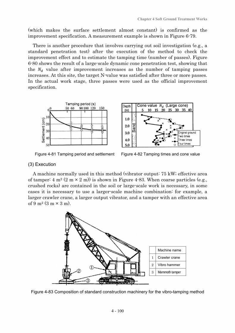
Chapter 4 Soft Ground Treatment Works
4 - 100
(which makes the surface settlement almost constant) is confirmed as the improvement specification. A measurement example is shown in Figure 6-79.
There is another procedure that involves carrying out soil investigation (e.g., a standard penetration test) after the execution of the method to check the improvement effect and to estimate the tamping time (number of passes). Figure 6-80 shows the result of a large-scale dynamic cone penetration test, showing that the value after improvement increases as the number of tamping passes increases. At this site, the target N-value was satisfied after three or more passes. In the actual work stage, three passes were used as the official improvement specification.
Figure 4-81 Tamping period and settlement Figure 4-82 Tamping times and cone value
(3) Execution
A machine normally used in this method (vibrator output: 75 kW; effective area of tamper: 4 m2 (2 m × 2 m)) is shown in Figure 4-83. When coarse particles (e.g., crushed rocks) are contained in the soil or large-scale work is necessary, in some cases it is necessary to use a larger-scale machine combination: for example, a larger crawler crane, a larger output vibrator, and a tamper with an effective area of 9 m2 (3 m × 3 m).
Machine name
1 Crawler crane
2 Vibro hammer
3 Mammoth tamper
Figure 4-83 Composition of standard construction machinery for the vibro-tamping method
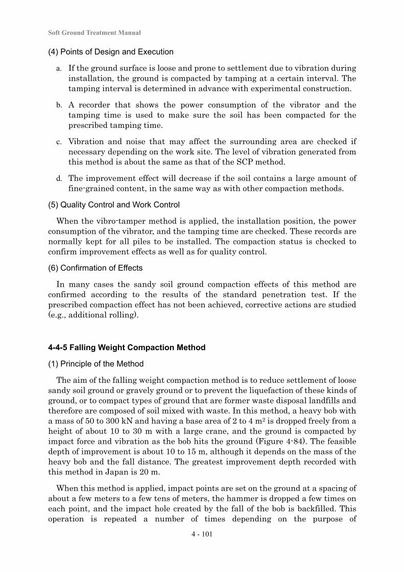
Soft Ground Treatment Manual
4 - 101
(4) Points of Design and Execution
a. If the ground surface is loose and prone to settlement due to vibration during installation, the ground is compacted by tamping at a certain interval. The tamping interval is determined in advance with experimental construction.
b. A recorder that shows the power consumption of the vibrator and the tamping time is used to make sure the soil has been compacted for the prescribed tamping time.
c. Vibration and noise that may affect the surrounding area are checked if necessary depending on the work site. The level of vibration generated from this method is about the same as that of the SCP method.
d. The improvement effect will decrease if the soil contains a large amount of fine-grained content, in the same way as with other compaction methods.
(5) Quality Control and Work Control
When the vibro-tamper method is applied, the installation position, the power consumption of the vibrator, and the tamping time are checked. These records are normally kept for all piles to be installed. The compaction status is checked to confirm improvement effects as well as for quality control.
(6) Confirmation of Effects
In many cases the sandy soil ground compaction effects of this method are confirmed according to the results of the standard penetration test. If the prescribed compaction effect has not been achieved, corrective actions are studied (e.g., additional rolling).
4-4-5 Falling Weight Compaction Method
(1) Principle of the Method
The aim of the falling weight compaction method is to reduce settlement of loose sandy soil ground or gravely ground or to prevent the liquefaction of these kinds of ground, or to compact types of ground that are former waste disposal landfills and therefore are composed of soil mixed with waste. In this method, a heavy bob with a mass of 50 to 300 kN and having a base area of 2 to 4 m2 is dropped freely from a height of about 10 to 30 m with a large crane, and the ground is compacted by impact force and vibration as the bob hits the ground (Figure 4-84). The feasible depth of improvement is about 10 to 15 m, although it depends on the mass of the heavy bob and the fall distance. The greatest improvement depth recorded with this method in Japan is 20 m.
When this method is applied, impact points are set on the ground at a spacing of about a few meters to a few tens of meters, the hammer is dropped a few times on each point, and the impact hole created by the fall of the bob is backfilled. This operation is repeated a number of times depending on the purpose of
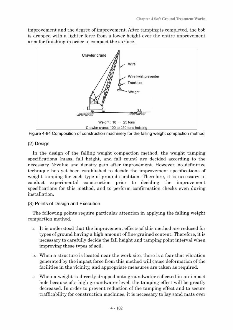
Chapter 4 Soft Ground Treatment Works
4 - 102
improvement and the degree of improvement. After tamping is completed, the bob is dropped with a lighter force from a lower height over the entire improvement area for finishing in order to compact the surface.
Weight : 10 〜 25 tons Crawler crane: 100 to 250 tons hoisting
Figure 4-84 Composition of construction machinery for the falling weight compaction method
(2) Design
In the design of the falling weight compaction method, the weight tamping specifications (mass, fall height, and fall count) are decided according to the necessary N-value and density gain after improvement. However, no definitive technique has yet been established to decide the improvement specifications of weight tamping for each type of ground condition. Therefore, it is necessary to conduct experimental construction prior to deciding the improvement specifications for this method, and to perform confirmation checks even during installation.
(3) Points of Design and Execution
The following points require particular attention in applying the falling weight compaction method.
a. It is understood that the improvement effects of this method are reduced for types of ground having a high amount of fine-grained content. Therefore, it is necessary to carefully decide the fall height and tamping point interval when improving these types of soil.
b. When a structure is located near the work site, there is a fear that vibration generated by the impact force from this method will cause deformation of the facilities in the vicinity, and appropriate measures are taken as required.
c. When a weight is directly dropped onto groundwater collected in an impact hole because of a high groundwater level, the tamping effect will be greatly decreased. In order to prevent reduction of the tamping effect and to secure trafficability for construction machines, it is necessary to lay sand mats over

Soft Ground Treatment Manual
4 - 103
the work surface so that the groundwater level becomes 1.5 to 2.0 m below the work surface.
(4) Quality Control and Work Control
In applying the falling weight compaction method, the tamping location, the heaviness of the weight, the fall height, and the depth of the impact hole (penetration of the weight) are confirmed. These records are normally kept for all impact positions.
(5) Confirmation of Effects
In many cases the ground compaction effects with this method are checked according to the results of the standard penetration test. If the prescribed compaction effect has not been achieved, necessary measures are studied (e.g., the implementation of additional tamping).
4-4-6 Static Compacted Sand Pile Method
(1) Principle of the Method
Like the SCP method, the static compacted sand pile method is applied for the purposes of increasing the bearing capacity and preventing the liquefaction of sandy soil ground, and for increasing the bearing capacity, accelerating consolidation, and reducing consolidation settlement of cohesive soil ground. Rather than dynamic injection using vibration energy as employed in the SCP method, compacted sand piles are created in the soil with static injection using the ascent and descent as well as the rotational energy of the casing (Figure 4-83).
Figure 4-85 Machinery for the static compacted sand pile method
This method has the following features.
Chapter 4 Soft Ground Treatment Works
4 - 104
a. Compared to the methods using vibration energy, it has less impact of displacement of the surrounding ground or of nearby structures.
b. Compared to the methods using vibration energy (Figure 4-2 and 4-3), it generates exceedingly little vibration or noise. Therefore, it can be applied to work sites in urban areas or near structures.
c. It is used for the same improvement purposes as those of the SCP method.
(2) Design
Since this method can obtain the same improvement effects as those of the SCP method in terms of sandy ground compaction, the replacement ratio is calculated in the same way as that for the SCP method.
(3) Execution
The static compacted sand drain method procedures include a method in which the casing is rotated with the rotating drive unit and pressure-fitting force is provided to the casing with the forced elevation device to create sand piles (with the process being the same as that for the ordinary SCP method), and a method in which a special diameter-enlargement excavation head is attached to the front end of the casing to create sand piles.
(4) Points of Design and Execution
The performance of the static compacted sand pile method is similar to that of the SCP method. However, an auxiliary means for penetration may be necessary for hard ground with an N-value of over 30. It is necessary to carry out sufficient studies in advance, including the implementation of experimental construction.
(5) Quality Control and Confirmation of Effects
Quality control of the materials used for the static compacted sand pile method and work control for this method are conducted in the same way as with the SCP method. The improvement effects of this method are checked according to the status of compaction for sandy soil ground, and according to consolidation acceleration or strength increase due to consolidation for cohesive soil ground, in the same way as with the SCP method.
4-4-7 Static Pressure Fit Compaction Method
(1) Principle of the Method
In the static pressure fit compaction method, with the aim of preventing the liquefaction of sandy soil ground, soft soil is improved by pressure fitting a highly fluid additive (soil mortar) into the ground to form solidification piles, in order to compact the ground and increase the density. This method has the following features.
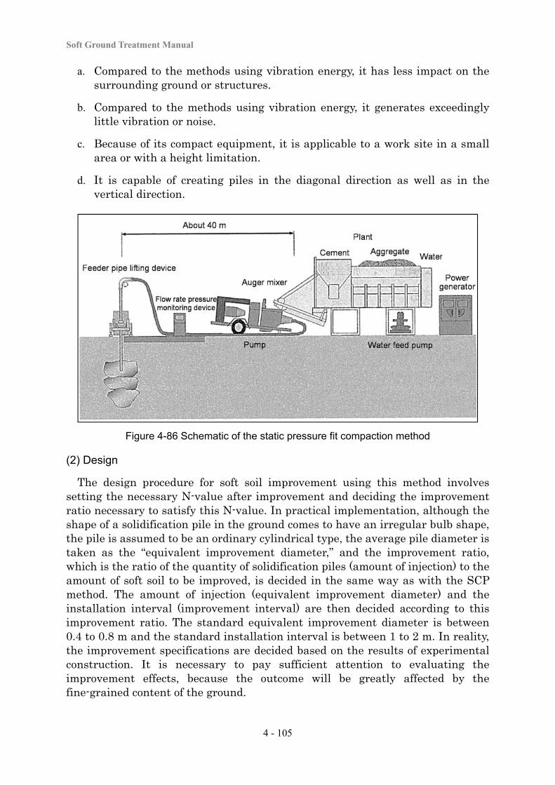
Soft Ground Treatment Manual
4 - 105
a. Compared to the methods using vibration energy, it has less impact on the surrounding ground or structures.
b. Compared to the methods using vibration energy, it generates exceedingly little vibration or noise.
c. Because of its compact equipment, it is applicable to a work site in a small area or with a height limitation.
d. It is capable of creating piles in the diagonal direction as well as in the vertical direction.
Figure 4-86 Schematic of the static pressure fit compaction method
(2) Design
The design procedure for soft soil improvement using this method involves setting the necessary N-value after improvement and deciding the improvement ratio necessary to satisfy this N-value. In practical implementation, although the shape of a solidification pile in the ground comes to have an irregular bulb shape, the pile is assumed to be an ordinary cylindrical type, the average pile diameter is taken as the “equivalent improvement diameter,” and the improvement ratio, which is the ratio of the quantity of solidification piles (amount of injection) to the amount of soft soil to be improved, is decided in the same way as with the SCP method. The amount of injection (equivalent improvement diameter) and the installation interval (improvement interval) are then decided according to this improvement ratio. The standard equivalent improvement diameter is between 0.4 to 0.8 m and the standard installation interval is between 1 to 2 m. In reality, the improvement specifications are decided based on the results of experimental construction. It is necessary to pay sufficient attention to evaluating the improvement effects, because the outcome will be greatly affected by the fine-grained content of the ground.
Chapter 4 Soft Ground Treatment Works
4 - 106
(3) Execution
The execution procedure involves drilling a hole in the ground with a small-diameter rod (about 70 mm in outer diameter) using a small boring machine, and filling mortar into the ground with a special filling pump. Because of this process, if there is a hard layer in the upper part of the ground, the method can easily penetrate it and improve the soft soil. It causes relatively less displacement in the ground or less damage to structures, and can be applied to locations where it is considered difficult to realize soil improvement (e.g., a site immediately under or very close to an existing structure). Gravel, sand, or special aggregate with appropriately adjusted fine-grained content is used as additive depending on the ground conditions. Major items for work control include the installation location, drilling angle, drilling depth, additive, additive feed amount, and ground displacement.
(4) Points of Design and Execution
The following points require particular attention in the design and execution of soft soil improvement using the static pressure fit compaction method.
a. If a structure is located near the improvement area, deformation or other shape changes may occur to the structure because of the expansion of the additive or of the ground treated with the injection of additive, and due to elevation of the pore water pressure in the soil. Therefore, it is necessary to pay attention to managing the injection pressure and the amount of injection, as well as possible deformation of structures in the vicinity.
b. When additive flows out of the injection range, it may cause problems to the surrounding environment (e.g., pollution of groundwater). It is therefore necessary to monitor water quality, including groundwater and public water, at an appropriate frequency before commencing work, during work, and after the completion of work.
(5) Quality Control and Work Control
The quality of additive materials is regularly checked in management tests with sampling. In the execution of the method, the installation position and interval are checked, and management is carried out for the installation depth, the amount of additive injected with pressure fitting, and the pressure-fitting pressure. Final confirmation is then made to confirm that the improved piles installed into each set depth have been created with the appropriate improvement diameter.
(6) Confirmation of Effects
The sandy soil ground compaction effects with this method are often checked according to the results of the standard penetration test. If the prescribed compaction effect has not been achieved, appropriate measures are studied, (e.g., the additional installation of piles).
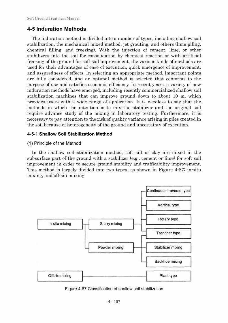
Soft Ground Treatment Manual
4 - 107
4-5 Induration Methods
The induration method is divided into a number of types, including shallow soil stabilization, the mechanical mixed method, jet grouting, and others (lime piling, chemical filling, and freezing). With the injection of cement, lime, or other stabilizers into the soil for consolidation by chemical reaction or with artificial freezing of the ground for soft soil improvement, the various kinds of methods are used for their advantages of ease of execution, quick emergence of improvement, and assuredness of effects. In selecting an appropriate method, important points are fully considered, and an optimal method is selected that conforms to the purpose of use and satisfies economic efficiency. In recent years, a variety of new induration methods have emerged, including recently commercialized shallow soil stabilization machines that can improve ground down to about 10 m, which provides users with a wide range of application. It is needless to say that the methods in which the intention is to mix the stabilizer and the original soil require advance study of the mixing in laboratory testing. Furthermore, it is necessary to pay attention to the risk of quality variance arising in piles created in the soil because of heterogeneity of the ground and uncertainty of execution.
4-5-1 Shallow Soil Stabilization Method
(1) Principle of the Method
In the shallow soil stabilization method, soft silt or clay are mixed in the subsurface part of the ground with a stabilizer (e.g., cement or lime) for soft soil improvement in order to secure ground stability and trafficability improvement. This method is largely divided into two types, as shown in Figure 4-87: in-situ mixing, and off-site mixing.
Figure 4-87 Classification of shallow soil stabilization
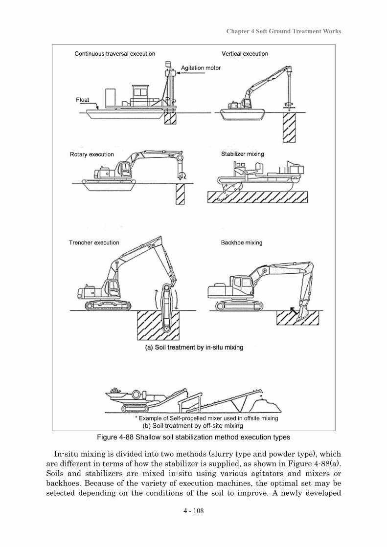
Chapter 4 Soft Ground Treatment Works
4 - 108
Figure 4-88 Shallow soil stabilization method execution types
In-situ mixing is divided into two methods (slurry type and powder type), which are different in terms of how the stabilizer is supplied, as shown in Figure 4-88(a). Soils and stabilizers are mixed in-situ using various agitators and mixers or backhoes. Because of the variety of execution machines, the optimal set may be selected depending on the conditions of the soil to improve. A newly developed
* Example of Self-propelled mixer used in offsite mixing (b) Soil treatment by off-site mixing
Soft Ground Treatment Manual
4 - 109
vertical agitator (trencher type) can improve the soil down to about 10 m. In off-site mixing, surface soils are excavated and brought off-site, where they are mixed with a stabilizer (e.g., cement) in an off-site plant for improvement, and the improved mixture is then brought back to the site for backfilling, as shown in Figure 4-88(b).
(2) Design
The purposes of the shallow soil stabilization method include improving the stability of the ground and improving trafficability, and the design is carried out accordingly. Specifically, load conditions are set to study the bearing capacity and other factors; the area of improvement, depth of improvement, and design strength are decided; and the type of stabilizer to use and the mixing quantity that satisfy the target design strength in a laboratory mixing test are selected. Total improvement, in which a consolidation plate is formed for soft soil improvement, is normally adopted. In deciding the mix proportions, the difference in strength between the laboratory mixing test results and the actual field results is taken into account.
(3) Execution
There are a variety of methods for executing the shallow soil stabilization method, as shown in Figure 4-88. An optimal method should be selected according to the qualities and properties of the ground, the depth of improvement, and the amount of soil to be improved.
(4) Points of Design and Execution
a. The strength or variability in the strength of the mixture is affected by the amount of stabilizer supplied and the stirring and mixing conditions. During the work, it is necessary to carry out sufficient work control regarding items related to stirring work, namely the amount of stabilizer supplied, the stirring time, and the number of rotations.
b. When the ground surface is soft, in some cases machines can tip over due to instability. Therefore it is necessary to confirm appropriate trafficability for construction machines in advance.
c. When cement or a cement-based stabilizer is used as a stabilizer, the elution of hexavalent chromium must be borne in mind.
d. When the stabilizer is spread over the ground surface in the form of powder, the spreading work may scatter dust. When quicklime is used, this substance generates heat, and therefore it is necessary to take sufficient precautions to secure the safety of workers and prevent damage to the surrounding environment due to dust.
e. The application of the off-site mixing method requires the excavation of the soft soil. Therefore, it is necessary to pay attention to the slope stability conditions, ground heaving, or reduction in the groundwater level.
Chapter 4 Soft Ground Treatment Works
4 - 110
(5) Quality Control and Work Control
The shallow soil stabilization method requires regular checks of the quality of the stabilizers used. In work control for the shallow soil stabilization method, it is necessary to confirm the mixing location and operational order at an appropriate frequency, and to record the improvement depth (thickness) and width, the duration of stirring, the number of rotations, and the amount of stabilizer supplied. Recording the depth of improvement and other data is normally conducted for all mixing runs or all operation runs. In many cases, general quality control items include the thickness of the improved layer, and implementation of a strength check of the improved soil using sampled cores and a sounding test of the improved soil for strength measurement. If the required quality has not been attained, the mix design or mixing procedure is corrected or modified.
(6) Confirmation of Effects
In the shallow soil stabilization method, the improvement effects are checked according to the status of ground stability, control of deformation, and improvement of trafficability.
Ground stability and control of deformation
Ground stability or deformation control effects are often checked with quality control, including strength testing of core samples of the improved soil, and ground monitoring of the ground after completion of the embankment. If the required stability or deformation control effects have not been attained, appropriate measures are studied, including changing or correcting the mix design or design strength as well as additional improvement.
Trafficability
Trafficability improvement effects are often checked with quality control including strength testing of core samples or sounding tests (e.g., the portable cone penetration test). If the required improvement effect has not been attained, appropriate measures are studied, including changing or correcting the mix design or design strength as well as additional improvement.
4-5-2 Deep Mixed Method (Mechanical Mixed Method)
(1) Principle of the Method
The mechanical mixed method is the method which creates a strong columnar, block or wall shaped stabilized soil mixture in the deep ground, by means of powder or slurry stabilizer (mainly cement-based) and the stabilizer in order to stir and mix the soft soil with agitator blades. The purposes of improvement with this method include increasing slip resistance, controlling deformation, reducing settlement, and preventing liquefaction. Since this method uses a chemical reaction for soft soil improvement, it has advantages in that it can create high-strength improved soil in a short time, generates relatively little noise or
Soft Ground Treatment Manual
4 - 111
vibration and thus does not seriously affect the surrounding environment, can improve both cohesive or sandy soils, and is applicable to sites adjacent to structures or residential buildings. (2) Design
Design concept
In the design, the area of improvement, depth of improvement, design strength, and other improvement specifications necessary for each purpose of improvement are decided, and a mix design that specifies the type and supply quantity of stabilizer necessary to obtain the design strength is decided. The following points require study depending on the purpose of improvement (i.e., embankment stability, control of settlement, or prevention of liquefaction).
a. Deciding design geotechnical parameters, loading conditions (type, size, etc.), and design conditions (tolerances, etc.)
b. Deciding the type of improvement (block type, pile type, etc.) and the improvement ratio
c. Selecting the area of improvement, depth of improvement, and strength of improvement
d. Selecting the checking method (checking that conforms to the purpose)
e. Selecting the method of improvement (stability supply method, pile diameter, etc.)
f. Selecting the method of work control and quality control (tolerances related to strength, etc.)
The types of improvement are largely divided into the “pile type” in which columns are laid out independently, and the “block type” in which columns are overlapped in order to make the multiple columns into a single improved body. As shown in Figure 4-89, in pile type improvement, improving piles are laid out at a certain interval in a rectangular or zigzag pattern to improve the soil. The “contacting column type,” in which columns are laid out in contact with each other with no interval, is categorized as the pile type as no improved areas are overlapped. The block type includes the “wall type,” in which a wall of improved soil is built in a single direction, and the “grid type,” in which improved bodies are formed in a grid pattern. The “contacting column overlapping type,” in which columns are overlapped with each other in the direction of major external force and caused to be in contact with each other in the direction perpendicular to that direction, is included in the block type. Pile type improvement is the basic solution for embankment stability or settlement control. Block type improvement is often used for reinforcement of the bearing capacity or settlement control of the foundations of structures (e.g., retaining walls). Although the block type is the basic choice for liquefaction control, the grid type is frequently used for its economic efficiency.
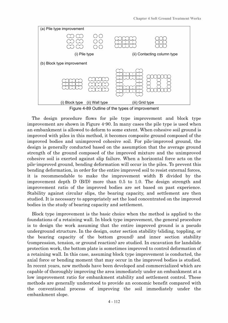
Chapter 4 Soft Ground Treatment Works
4 - 112
(a) Pile type improvement
(i) Pile type (ii) Contacting column type
(b) Block type improvement
(i) Block type (ii) Wall type (iii) Grid type
Figure 4-89 Outline of the types of improvement
The design procedure flows for pile type improvement and block type improvement are shown in Figure 4-90. In many cases the pile type is used when an embankment is allowed to deform to some extent. When cohesive soil ground is improved with piles in this method, it becomes composite ground composed of the improved bodies and unimproved cohesive soil. For pile-improved ground, the design is generally conducted based on the assumption that the average ground strength of the ground composed of the improved mixture and the unimproved cohesive soil is exerted against slip failure. When a horizontal force acts on the pile-improved ground, bending deformation will occur in the piles. To prevent this bending deformation, in order for the entire improved soil to resist external forces, it is recommendable to make the improvement width B divided by the improvement depth D (B/D) more than 0.5 to 1.0. The design strength and improvement ratio of the improved bodies are set based on past experience. Stability against circular slips, the bearing capacity, and settlement are then studied. It is necessary to appropriately set the load concentrated on the improved bodies in the study of bearing capacity and settlement.
Block type improvement is the basic choice when the method is applied to the foundations of a retaining wall. In block type improvement, the general procedure is to design the work assuming that the entire improved ground is a pseudo underground structure. In the design, outer section stability (sliding, toppling, or the bearing capacity of the bottom ground) and inner section stability (compression, tension, or ground reaction) are studied. In excavation for landslide protection work, the bottom plate is sometimes improved to control deformation of a retaining wall. In this case, assuming block type improvement is conducted, the axial force or bending moment that may occur in the improved bodies is studied. In recent years, new methods have been developed and commercialized which are capable of thoroughly improving the area immediately under an embankment at a low improvement ratio for embankment stability and settlement control. These methods are generally understood to provide an economic benefit compared with the conventional process of improving the soil immediately under the embankment slope.
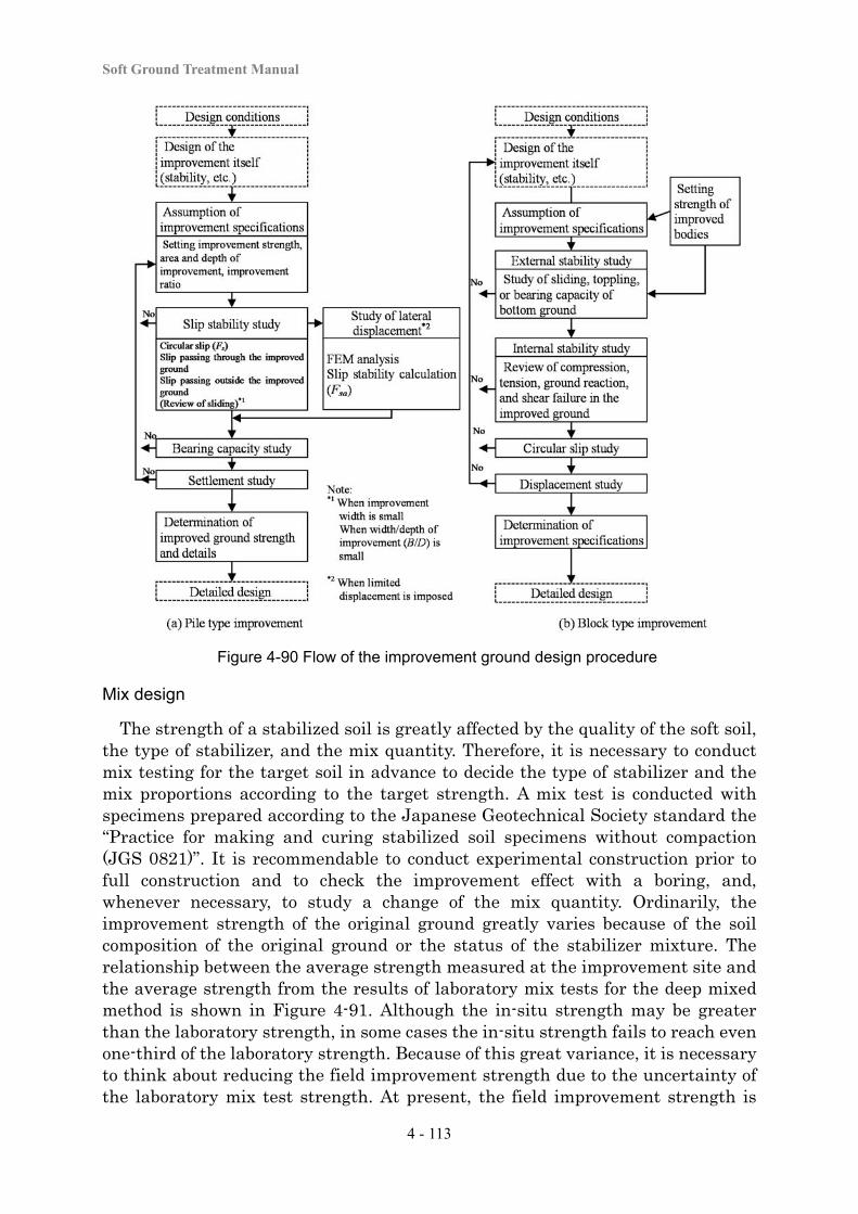
Soft Ground Treatment Manual
4 - 113
Figure 4-90 Flow of the improvement ground design procedure
Mix design
The strength of a stabilized soil is greatly affected by the quality of the soft soil, the type of stabilizer, and the mix quantity. Therefore, it is necessary to conduct mix testing for the target soil in advance to decide the type of stabilizer and the mix proportions according to the target strength. A mix test is conducted with specimens prepared according to the Japanese Geotechnical Society standard the “Practice for making and curing stabilized soil specimens without compaction (JGS 0821)”. It is recommendable to conduct experimental construction prior to full construction and to check the improvement effect with a boring, and, whenever necessary, to study a change of the mix quantity. Ordinarily, the improvement strength of the original ground greatly varies because of the soil composition of the original ground or the status of the stabilizer mixture. The relationship between the average strength measured at the improvement site and the average strength from the results of laboratory mix tests for the deep mixed method is shown in Figure 4-91. Although the in-situ strength may be greater than the laboratory strength, in some cases the in-situ strength fails to reach even one-third of the laboratory strength. Because of this great variance, it is necessary to think about reducing the field improvement strength due to the uncertainty of the laboratory mix test strength. At present, the field improvement strength is
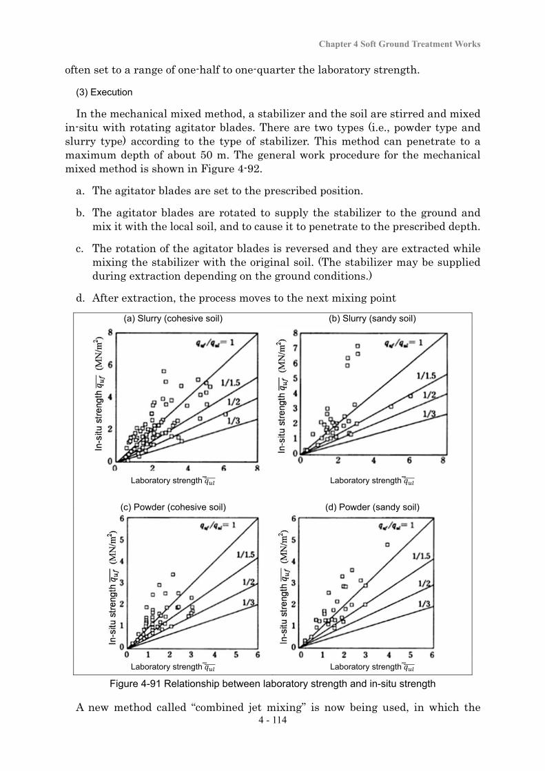
Chapter 4 Soft Ground Treatment Works
4 - 114
often set to a range of one-half to one-quarter the laboratory strength.
(3) Execution
In the mechanical mixed method, a stabilizer and the soil are stirred and mixed in-situ with rotating agitator blades. There are two types (i.e., powder type and slurry type) according to the type of stabilizer. This method can penetrate to a maximum depth of about 50 m. The general work procedure for the mechanical mixed method is shown in Figure 4-92.
a. The agitator blades are set to the prescribed position.
b. The agitator blades are rotated to supply the stabilizer to the ground and mix it with the local soil, and to cause it to penetrate to the prescribed depth.
c. The rotation of the agitator blades is reversed and they are extracted while mixing the stabilizer with the original soil. (The stabilizer may be supplied during extraction depending on the ground conditions.)
d. After extraction, the process moves to the next mixing point
(a) Slurry (cohesive soil) (b) Slurry (sandy soil)
Laboratory strength Laboratory strength
(c) Powder (cohesive soil) (d) Powder (sandy soil)
Laboratory strength Laboratory strength
Figure 4-91 Relationship between laboratory strength and in-situ strength
A new method called “combined jet mixing” is now being used, in which the

Soft Ground Treatment Manual
4 - 115
stabilizer is jetted with high pressure from the front end of the agitator blades in order to cut the soil for mixing at the same time as mechanical mixing. The execution procedure of the combined jet mixing method is illustrated in Figure 4-93.
Figure 4-92 The mechanical mixing method execution procedure
Figure 4-93 Deep mixed method (combined jet mixing) execution procedure
Chapter 4 Soft Ground Treatment Works
4 - 116
(4) Points of Design and Execution
The following points require attention in the design and execution of this method.
a. In designing soft soil improvement immediately under an embankment behind an abutment, it is necessary to appropriately decide the improvement timing, improvement ratio, improvement width, improvement depth, and execution method in order to prevent the occurrence of lateral movement of the abutment.
b. With the mechanical mixed method, the strength of the improved bodies is affected by the quantity of stabilizer supplied, and the performance of stirring and mixing. It is necessary to conduct sufficient work control for items including the quantity of stabilizer supplied, the rotational speed of the agitator blades, and the speed of penetration or extraction during execution of the soft soil improvement work. In particular, caution is required when this method is applied to ground with a high degree of sensitivity, as the quantity of stabilizer supplied easily becomes irregular according to the type of method used to supply the stabilizer during extraction.
c. When a soil with a high content of organic matter (e.g., peaty soil ground) is improved, a large amount of stabilizer is generally necessary to obtain the prescribed level of strength.
d. Although the laboratory mix proportion test can provide a rough idea about the appropriate amount of stabilizer to be supplied, the actual improvement strength at the site tends to vary depending on the status of stratification of the ground or the precision of execution. Therefore, on-site testing is conducted to confirm the improvement effect and, depending on the test results, to modify the amount of stabilizer supplied.
e. The ground will be temporarily disturbed by the agitator blade, which may trigger strength reduction, so it is necessary to pay attention to maintaining trafficability for construction machines.
f. As a method with low vibration and noise, this method is frequently used in work sites located near structures. However, it is possible that the volumetric change or pneumatic pressure and injection pressure associated with or resulting from the supply of the stabilizer can affect adjacent structures. The recently developed earth-removal type low-displacement deep mixed method is one solution to this situation, and it is necessary to study its use when the work site is bound by strict displacement-related restrictions (e.g., the proximity of residential buildings).
g. An important point in wall-type or grid-type improvement is to secure continuous integration of joints that does not pose a strength disadvantage. To this end, strict installation location precision should be maintained.
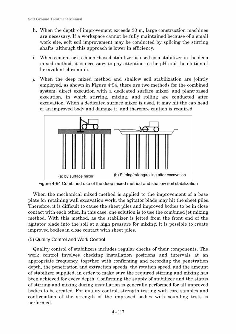
Soft Ground Treatment Manual
4 - 117
h. When the depth of improvement exceeds 30 m, large construction machines are necessary. If a workspace cannot be fully maintained because of a small work site, soft soil improvement may be conducted by splicing the stirring shafts, although this approach is lower in efficiency.
i. When cement or a cement-based stabilizer is used as a stabilizer in the deep mixed method, it is necessary to pay attention to the pH and the elution of hexavalent chromium.
j. When the deep mixed method and shallow soil stabilization are jointly employed, as shown in Figure 4-94, there are two methods for the combined system: direct execution with a dedicated surface mixer; and plant-based execution, in which stirring, mixing, and rolling are conducted after excavation. When a dedicated surface mixer is used, it may hit the cap head of an improved body and damage it, and therefore caution is required.
(a) by surface mixer (b) Stirring/mixing/rolling after excavation
Figure 4-94 Combined use of the deep mixed method and shallow soil stabilization
When the mechanical mixed method is applied to the improvement of a base plate for retaining wall excavation work, the agitator blade may hit the sheet piles. Therefore, it is difficult to cause the sheet piles and improved bodies to be in close contact with each other. In this case, one solution is to use the combined jet mixing method. With this method, as the stabilizer is jetted from the front end of the agitator blade into the soil at a high pressure for mixing, it is possible to create improved bodies in close contact with sheet piles.
(5) Quality Control and Work Control
Quality control of stabilizers includes regular checks of their components. The work control involves checking installation positions and intervals at an appropriate frequency, together with confirming and recording the penetration depth, the penetration and extraction speeds, the rotation speed, and the amount of stabilizer supplied, in order to make sure the required stirring and mixing has been achieved for every depth. Confirming the supply of stabilizer and the status of stirring and mixing during installation is generally performed for all improved bodies to be created. For quality control, strength testing with core samples and confirmation of the strength of the improved bodies with sounding tests is performed.
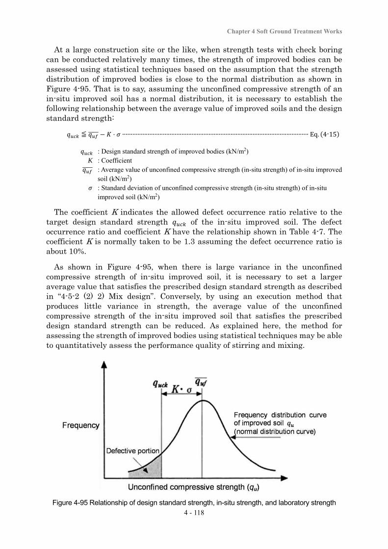
Chapter 4 Soft Ground Treatment Works
4 - 118
At a large construction site or the like, when strength tests with check boring can be conducted relatively many times, the strength of improved bodies can be assessed using statistical techniques based on the assumption that the strength distribution of improved bodies is close to the normal distribution as shown in Figure 4-95. That is to say, assuming the unconfined compressive strength of an in-situ improved soil has a normal distribution, it is necessary to establish the following relationship between the average value of improved soils and the design standard strength:
≦ ⋅ ∙∙∙∙∙∙∙∙∙∙∙∙∙∙∙∙∙∙∙∙∙∙∙∙∙∙∙∙∙∙∙∙∙∙∙∙∙∙∙∙∙∙∙∙∙∙∙∙∙∙∙∙∙∙∙∙∙∙∙∙∙∙∙∙∙∙∙∙∙∙∙∙∙∙∙∙∙∙∙∙∙∙∙∙∙∙∙∙∙∙∙∙∙∙∙∙∙∙∙∙∙∙∙∙∙∙∙∙∙∙ Eq. 4-15
: Design standard strength of improved bodies (kN/m2) K : Coefficient : Average value of unconfined compressive strength (in-situ strength) of in-situ improved
soil (kN/m2) : Standard deviation of unconfined compressive strength (in-situ strength) of in-situ
improved soil (kN/m2)
The coefficient K indicates the allowed defect occurrence ratio relative to the target design standard strength of the in-situ improved soil. The defect occurrence ratio and coefficient K have the relationship shown in Table 4-7. The coefficient K is normally taken to be 1.3 assuming the defect occurrence ratio is about 10%.
As shown in Figure 4-95, when there is large variance in the unconfined compressive strength of in-situ improved soil, it is necessary to set a larger average value that satisfies the prescribed design standard strength as described in “4-5-2 (2) 2) Mix design”. Conversely, by using an execution method that produces little variance in strength, the average value of the unconfined compressive strength of the in-situ improved soil that satisfies the prescribed design standard strength can be reduced. As explained here, the method for assessing the strength of improved bodies using statistical techniques may be able to quantitatively assess the performance quality of stirring and mixing.
Figure 4-95 Relationship of design standard strength, in-situ strength, and laboratory strength
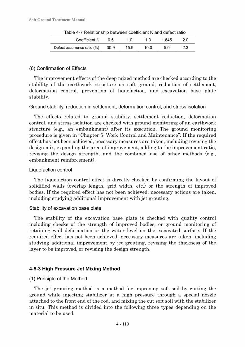
Soft Ground Treatment Manual
4 - 119
Table 4-7 Relationship between coefficient K and defect ratio
Coefficient K 0.5 1.0 1.3 1.645 2.0
Defect occurrence ratio (%) 30.9 15.9 10.0 5.0 2.3
(6) Confirmation of Effects
The improvement effects of the deep mixed method are checked according to the stability of the earthwork structure on soft ground, reduction of settlement, deformation control, prevention of liquefaction, and excavation base plate stability.
Ground stability, reduction in settlement, deformation control, and stress isolation
The effects related to ground stability, settlement reduction, deformation control, and stress isolation are checked with ground monitoring of an earthwork structure (e.g., an embankment) after its execution. The ground monitoring procedure is given in “Chapter 5: Work Control and Maintenance”. If the required effect has not been achieved, necessary measures are taken, including revising the design mix, expanding the area of improvement, adding to the improvement ratio, revising the design strength, and the combined use of other methods (e.g., embankment reinforcement).
Liquefaction control
The liquefaction control effect is directly checked by confirming the layout of solidified walls (overlap length, grid width, etc.) or the strength of improved bodies. If the required effect has not been achieved, necessary actions are taken, including studying additional improvement with jet grouting.
Stability of excavation base plate
The stability of the excavation base plate is checked with quality control including checks of the strength of improved bodies, or ground monitoring of retaining wall deformation or the water level on the excavated surface. If the required effect has not been achieved, necessary measures are taken, including studying additional improvement by jet grouting, revising the thickness of the layer to be improved, or revising the design strength.
4-5-3 High Pressure Jet Mixing Method
(1) Principle of the Method
The jet grouting method is a method for improving soft soil by cutting the ground while injecting stabilizer at a high pressure through a special nozzle attached to the front end of the rod, and mixing the cut soft soil with the stabilizer in-situ. This method is divided into the following three types depending on the material to be used.
Chapter 4 Soft Ground Treatment Works
4 - 120
a. Grout jet (single-pipe type)
b. Grout and air jet (double-pipe type)
c. Water, air, and grout jet (triple-pipe type)
Of these types, the second and third include methods that are capable of improving soil to a maximum diameter of up to 5 m, or other methods that are capable of creating a restricted improvement diameter by controlling the angle of the jet flows. The third type, in which highly compressed water is used to cut the soil and the stabilizer is filled at low pressure, is capable of improving soils without causing much displacement in the surrounding ground.
The purposes of improvement with the jet grouting method include improving the outcome of the mechanical mixed method as well as increasing ground stability, reducing settlement, controlling deformation, and preventing liquefaction. Due to its use of compact machines, this method is suitable for application to ground improvement in a small space. Since it uses a small-diameter rod and the soil is cut with a highly pressurized jet for soft soil improvement, it has the advantage of being able to improve soil near or under an existing structure. On the other hand, because this method has poorer efficiency than the mechanical mixed method, in many cases jet grouting is more frequently used to protect the base of a shield or as an auxiliary method for constructing retaining works (e.g., underpinning). Since the excavated earth is discharged in the form of muck mixed with the stabilizer, it is necessary to properly carry out its disposal.
(2) Design
In the design procedure for the jet grouting method, the area of improvement and the depth of improvement are decided according to their respective purposes of use, in the same way as in the mechanical mixed method. The strength of improved bodies or the effective diameter is mostly decided for each method based on the ground conditions. When a strength or effective diameter other than the prescribed one is used, or when the ground to be improved is a special type for which there is no past record of this method being applied, the improvement specifications are decided based on fully studying mix testing and experimental construction to be carried out in advance.
(3) Execution
A sample of the grout jet method (single-pipe) execution procedure is shown in Figure 4-96. This type basically uses a boring machine in the same way as in the chemical injection method. A series of operations is conducted, including drilling the ground to the target depth, high-pressure jetting the stabilizer into the drilled hole, cutting the ground and mixing the stabilizer with the cut soil, and extracting the rod at a prescribed speed.
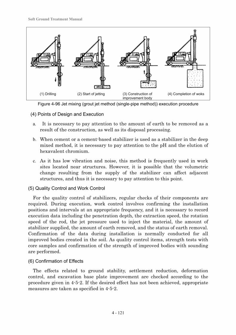
Soft Ground Treatment Manual
4 - 121
(1) Drilling (2) Start of jetting (3) Construction of improvement body
(4) Completion of woks
Figure 4-96 Jet mixing (grout jet method (single-pipe method)) execution procedure
(4) Points of Design and Execution
a. It is necessary to pay attention to the amount of earth to be removed as a result of the construction, as well as its disposal processing.
b. When cement or a cement-based stabilizer is used as a stabilizer in the deep mixed method, it is necessary to pay attention to the pH and the elution of hexavalent chromium.
c. As it has low vibration and noise, this method is frequently used in work sites located near structures. However, it is possible that the volumetric change resulting from the supply of the stabilizer can affect adjacent structures, and thus it is necessary to pay attention to this point.
(5) Quality Control and Work Control
For the quality control of stabilizers, regular checks of their components are required. During execution, work control involves confirming the installation positions and intervals at an appropriate frequency, and it is necessary to record execution data including the penetration depth, the extraction speed, the rotation speed of the rod, the jet pressure used to inject the material, the amount of stabilizer supplied, the amount of earth removed, and the status of earth removal. Confirmation of the data during installation is normally conducted for all improved bodies created in the soil. As quality control items, strength tests with core samples and confirmation of the strength of improved bodies with sounding are performed.
(6) Confirmation of Effects
The effects related to ground stability, settlement reduction, deformation control, and excavation base plate improvement are checked according to the procedure given in 4-5-2. If the desired effect has not been achieved, appropriate measures are taken as specified in 4-5-2.
Chapter 4 Soft Ground Treatment Works
4 - 122
4-5-4 Lime Pile Stabilization Method
(1) Principle of the Method
In the lime pile method, a powder stabilizer mainly composed of quicklime is pressed into the soft ground to create piles in the soil, using the excellent water absorption and expansion effects of quicklime. For cohesive soil ground, the benefits of this method include reducing the water content of the ground and consolidating the entire ground as composite ground composed of the water-hardened piles and consolidation-reinforced soil. Regarding the benefits for sandy soil ground, the hydration reaction of quicklime causes volumetric expansion to compact the surrounding loose sandy soil and increase the density of the ground and make it harder for liquefaction to occur. Thus, the major purposes of this method include increasing the bearing capacity of the ground, reducing settlement, preventing slip failure, and preventing liquefaction.
It is understood that the reduction in water content when using a powder stabilizer mainly composed of quicklime is caused by the water absorption reaction generated by quicklime as it changes into slaked lime and the capillary action as water from the surrounding soil is drawn into the generated slaked lime. In the water absorption reaction during slaking, the quicklime absorbs an amount of water equivalent to 32% of the quantity of quicklime and reacts with the absorbed water, with its volume expanding to about twice the original volume. The generated dry-state slaked lime continues to absorb water through capillary action until it reaches equilibrium with the surrounding soil and finally becomes wet-state slaked lime. Advantages of this method are that it needs no surcharge and quickly exerts its effect. However, when the pile infiltrates into a water-bearing sand layer or is in contact with surface water, its effectiveness will seriously decrease. In addition, high heat is generated due to the water-absorption action, and it is necessary to pay attention to sanitation and security when storing and handling the lime stabilizer.
(2) Design
In the design procedure for the lime pile method, the area of improvement, depth of improvement, design strength of the improved ground, and target void ratio are decided, and the improvement specifications, including the type and quantity of stabilizer to be supplied, the pile diameter, and the installation interval, are decided to satisfy the design strength of the improved ground and the target void ratio. The following points are studied in the design for the purpose of increasing the strength of the cohesive soil ground.
a. Calculation of the water content reduction of the ground after improvement from the lime pile amount supplied
b. Calculation of the void ratio of the ground after improvement due to the water content reduction
c. Determination of the shear strength of the ground after improvement
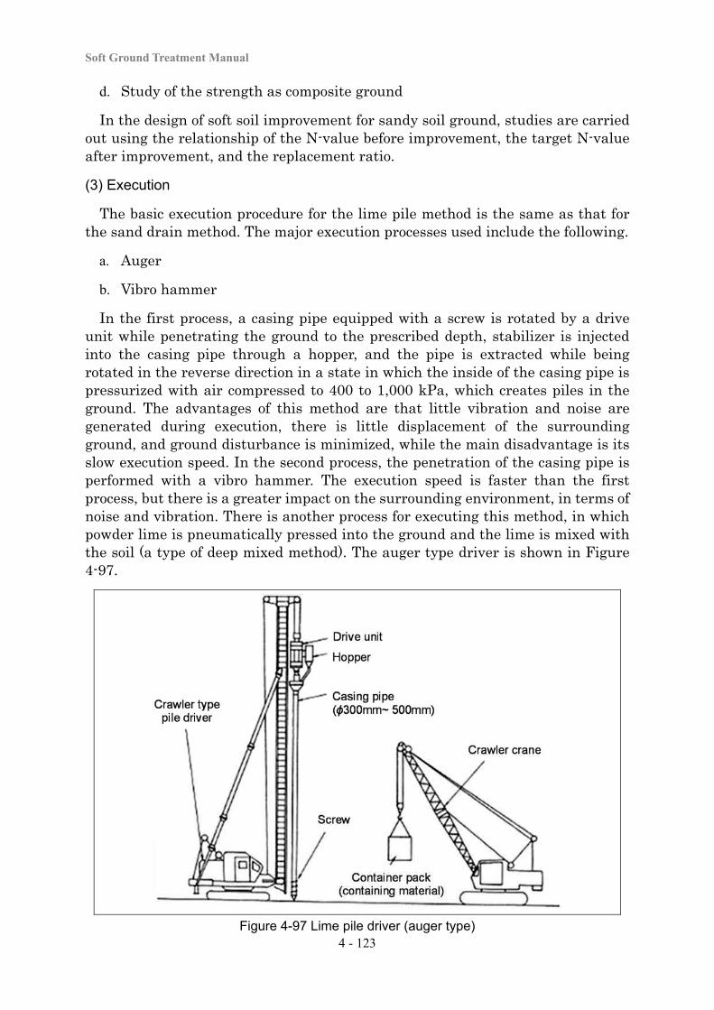
Soft Ground Treatment Manual
4 - 123
d. Study of the strength as composite ground
In the design of soft soil improvement for sandy soil ground, studies are carried out using the relationship of the N-value before improvement, the target N-value after improvement, and the replacement ratio.
(3) Execution
The basic execution procedure for the lime pile method is the same as that for the sand drain method. The major execution processes used include the following.
a. Auger
b. Vibro hammer
In the first process, a casing pipe equipped with a screw is rotated by a drive unit while penetrating the ground to the prescribed depth, stabilizer is injected into the casing pipe through a hopper, and the pipe is extracted while being rotated in the reverse direction in a state in which the inside of the casing pipe is pressurized with air compressed to 400 to 1,000 kPa, which creates piles in the ground. The advantages of this method are that little vibration and noise are generated during execution, there is little displacement of the surrounding ground, and ground disturbance is minimized, while the main disadvantage is its slow execution speed. In the second process, the penetration of the casing pipe is performed with a vibro hammer. The execution speed is faster than the first process, but there is a greater impact on the surrounding environment, in terms of noise and vibration. There is another process for executing this method, in which powder lime is pneumatically pressed into the ground and the lime is mixed with the soil (a type of deep mixed method). The auger type driver is shown in Figure 4-97.
Figure 4-97 Lime pile driver (auger type)
Chapter 4 Soft Ground Treatment Works
4 - 124
(4) Points of Design and Execution
The following points require attention with respect to the design and execution of this method.
a. Piles are usually 0.3 to 0.5 m in diameter, and in many cases the driving interval is between 0.75 and 1.5 m. Caution is necessary with the vibro hammer type, because driving can cause displacement in the side ground depending on the driving interval.
b. The top part of each lime pile should be empty for about 1 m, and this part is backfilled with clay or mountain sand. This is to prevent ground uplift as the expanding force of the pile works in the vertical direction, and it also prevents the inflow of surface water.
c. Quicklime generates high heat as it slakes and absorbs water. The generated heat may rise to a maximum of 300 to 400˚C around the border of the pile and the ground. Since the area between the four piles can be heated up to over 60˚C, caution is necessary regarding water content during handling, and clothes and gloves are used to avoid burns due to the generation of heat.
d. After the injection of quicklime, if the air pressure adjustment is inadequately performed upon completion of the casing pipe extraction or if the quicklime starts to react in the casing pipe, it will not be possible for the quicklime to drop down. If this happens, the quicklime could blow upward when the casing pipe is pulled up. Therefore, it is necessary to provide workers with dust masks, goggles, etc., and to pay sufficient attention when the pipe is being pulled up.
e. Since it is possible that the ground strength will have dropped immediately after driving, it is recommendable to set steel plates on the ground even if trafficability is secured.
f. Submission of a report to the competent fire department is required when quicklime (defined as a material containing over 80% calcium oxide) in a quantity of over 500 kg is handled or stored.
(5) Quality Control and Work Control
For the materials used in the lime pile method, the quality of stabilizers is regularly checked. In applying this method, the driving position and interval are confirmed at an appropriate frequency. The penetration depth, the amount of material to be injected, and the pressure of compressed air are managed to confirm that the prescribed material has been supplied into the ground, and these data are recorded. Confirmation and recording of the penetration depth, the amount of material injected, and other data during driving is normally conducted for all piles created. The strength of the ground between piles is also checked as part of the quality control.
Soft Ground Treatment Manual
4 - 125
(6) Confirmation of Effects
The effects with respect to ground stability, settlement reduction, and compaction of the sandy soil ground are checked.
Ground stability and settlement reduction
The ground stability and settlement reduction effects are confirmed with settlement and stability management based on ground monitoring after the construction of an earthwork structure (e.g., an embankment). The ground monitoring procedure is as specified in “Chapter 5: Work Control and Maintenance”. If the required effect has not been achieved, appropriate measures are studied, including adding to or changing the area of improvement or the improvement ratio.
Sandy soil ground compaction effects
The sandy soil ground compaction effects are checked by measuring N-values in the ground among the piles after completion. If the required liquefaction control effect has not been achieved, appropriate measures are studied, including the additional installation of piles.
4-5-5 Chemical Grouting Method
(1) Principle of the Method
In the chemical injection method, grouting material is injected into voids in the soil to improve the ground. The purposes of improvement include reducing the permeability of the ground, increasing ground strength, and preventing liquefaction. This method requires a small set of equipment and a short time for set-up, and it is applicable to work sites in a small space. Also, almost no vibration or noise is generated from this method. Since it uses a small-diameter rod to inject the grouting material for improvement, it has the advantage that soft soil improvement using this method is feasible at a site adjacent to or under an existing structure. On the other hand, its improvement effect is not easily confirmed, and water quality monitoring is essential to prevent groundwater pollution due to the grouting material. Depending on the situation, this method can cause displacement in the ground or deformation of a nearby structure, and therefore it requires appropriate work control.
The chemical injection method has mainly been applied to temporary work (e.g., for preventing the upwelling of spring water in underground excavation work, or preventing the collapse of natural ground). Thanks to recent progress in the development of grouting material and injection methods, this method is now being applied to preventing the liquefaction of ground under existing structures. Grouting materials used in this method are largely divided into solution-type chemicals and suspension-type chemicals. For the mode of injection, grouting material is injected into sandy soil ground in the form of an infiltration injection, or the grouting material is infiltrated into the soil particle voids. For cohesive soil
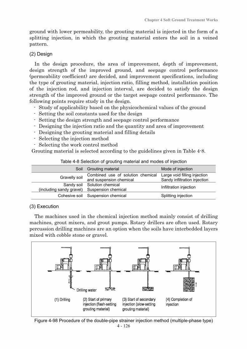
Chapter 4 Soft Ground Treatment Works
4 - 126
ground with lower permeability, the grouting material is injected in the form of a splitting injection, in which the grouting material enters the soil in a veined pattern.
(2) Design
In the design procedure, the area of improvement, depth of improvement, design strength of the improved ground, and seepage control performance (permeability coefficient) are decided, and improvement specifications, including the type of grouting material, injection ratio, filling method, installation position of the injection rod, and injection interval, are decided to satisfy the design strength of the improved ground or the target seepage control performance. The following points require study in the design.
- Study of applicability based on the physicochemical values of the ground - Setting the soil constants used for the design - Setting the design strength and seepage control performance - Designing the injection ratio and the quantity and area of improvement - Designing the grouting material and filling details - Selecting the injection method - Selecting the work control method
Grouting material is selected according to the guidelines given in Table 4-8.
Table 4-8 Selection of grouting material and modes of injection
Soil Grouting material Mode of injection
Gravelly soil Combined use of solution chemical and suspension chemical
Large void filling injection Sandy infiltration injection
Sandy soil (including sandy gravel)
Solution chemical Suspension chemical
Infiltration injection
Cohesive soil Suspension chemical Splitting injection
(3) Execution
The machines used in the chemical injection method mainly consist of drilling machines, grout mixers, and grout pumps. Rotary drillers are often used. Rotary percussion drilling machines are an option when the soils have interbedded layers mixed with cobble stone or gravel.
Figure 4-98 Procedure of the double-pipe strainer injection method (multiple-phase type)

Soft Ground Treatment Manual
4 - 127
Figure 4-99 Execution procedure with the double-pipe double-packer injection method
For the injection method, the double-pipe strainer method (single-phase and multiple-phase types) and double-pipe double-packer method are used. These injection methods are applied according to the type of ground and they have different improvement effects. Therefore, careful selection is necessary based on a full study of the purpose or ground conditions. Figure4-98 shows the basic execution procedure with the double-pipe strainer injection method (multiple-phase type). Figure 4-99 shows the execution procedure with the double-pipe double-packer injection method.
(4) Points of Design and Execution
Points in design
Important points in the design include deciding the injection area and the amount of injection relative to the ground conditions in order to obtain the effect that conforms to the purpose of injection, and selecting the optimal grouting material and injection method that conform to the purpose of injection. It is also important to conduct sufficient soil property and groundwater investigations and
Chapter 4 Soft Ground Treatment Works
4 - 128
understand the ground conditions (including the status of ground stratification, the soil void ratio, and groundwater veins) as early as possible in the design stage in order to avoid harmful influences on the living environment due to the outflow of grouting material outside the improvement area.
It is also recommendable to conduct field injection testing to check if the selected grouting material and injection method are appropriate and to confirm the necessary amount of injection, and to consider changing the injection plan based on the test results.
Points in execution
The following points require particular attention in the execution of the chemical injection method.
a. If a structure is located near an injection hole, ground expansion resulting from an increase in pressure during injection can cause deformation of the structure or other shape changes. Therefore, it is necessary to pay attention to the injection pressure and management of the amount of grouting material to be injected.
b. If a chemical solution flows outside the injection area in an unconsolidated state, it could cause harmful damage to the surrounding environment (e.g., groundwater pollution or plant mortality). Therefore, it is necessary to appropriately select the grouting material and injection method. It is also essential to conduct appropriate storage of the grouting material as well as disposal of residual materials or cleansing of machines in compliance with the treatment or disposal standards specified by the relevant laws or regulations.
c. Water quality monitoring of groundwater and public water is conducted periodically before, during, and after execution.
d. The locations and kinds of buried materials are investigated in advance to avoid damaging them during the drilling of injection holes.
(5) Work Control
The quality of grouting material in use is regularly checked. In applying the chemical injection method, it is necessary to check the area of injection (position, orientation, and depth of injection holes), properly manage the injection pressure and the amount of injection, and monitor the surrounding conditions during execution to confirm that injection has been properly conducted. When this method is applied for the prevention of liquefaction, core samples taken after execution are checked with a strength test.
(6) Confirmation of Effects
Effects of increasing ground strength and seepage control performance
The effects of increasing ground strength and seepage control performance are checked with a sounding test, a strength test with core samples of the improved
Soft Ground Treatment Manual
4 - 129
bodies, or a field permeability test. If the required effect has not been achieved, necessary measures are studied, including additional injection or a change in the area of improvement.
Control of liquefaction
The effect of liquefaction control is checked with strength testing with core samples taken after execution. If the required effect has not been achieved, necessary measures are studied, including additional injection or a change in the area of improvement.
4-5-6 Freezing Method
(1) Principle of the Method
The freezing method is a temporary work method in which the ground is temporarily frozen to secure stability and seepage control of the excavation surface when drilling soft ground or permeable ground located under the groundwater level. The temperature of pore water in the ground is lowered to turn it into ice and create a frozen soil wall without mixing any solidifying material into the ground. After completion, the frozen soil wall melts and returns to the original soil, and its original permeability is restored, which is an excellent and environmentally friendly advantage. Although the freezing method is generally understood to be a costly method, it is applicable to complicated ground consisting of soils having various properties. In addition, there is no depth limitation once the freezing pipe can be buried. Therefore, it is normally used for protection of the starting and arrival sections in shield tunneling work or underground connections, or at river or railroad track crossings.
(2) Design
In the design procedure for the freezing method, the area of freezing, depth of freezing, design strength of frozen soil walls, or seepage control performance (permeability coefficient) is decided depending on the application purpose, and the improvement specifications are decided, including the installation interval of freezing piping and the duration of freezing necessary to form the target frozen soil walls. When buried materials exist underground, it is necessary to study the displacement of the surrounding ground associated with freezing and melting.
(3) Execution
The work procedure for this method involves installing freezing pipes in the ground at an appropriate interval, circulating a coolant solution at about -20˚C to -30˚C in the freezing pipe, and building up frozen soil in the ground (in concentric circles around each freezing pipe) to form columns of frozen soil, as shown in Figure 4-100. The columns of frozen soil that build up over time come into contact with adjacent columns of frozen soil to ultimately create a continuous frozen soil wall. The installation interval of the freezing piping is often set to about 0.8 m in
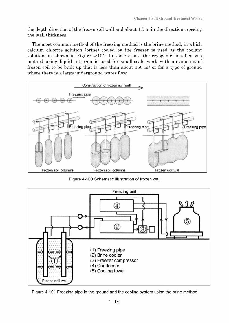
Chapter 4 Soft Ground Treatment Works
4 - 130
the depth direction of the frozen soil wall and about 1.5 m in the direction crossing the wall thickness.
The most common method of the freezing method is the brine method, in which calcium chlorite solution (brine) cooled by the freezer is used as the coolant solution, as shown in Figure 4-101. In some cases, the cryogenic liquefied gas method using liquid nitrogen is used for small-scale work with an amount of frozen soil to be built up that is less than about 150 m3 or for a type of ground where there is a large underground water flow.
Figure 4-100 Schematic illustration of frozen wall
Figure 4-101 Freezing pipe in the ground and the cooling system using the brine method
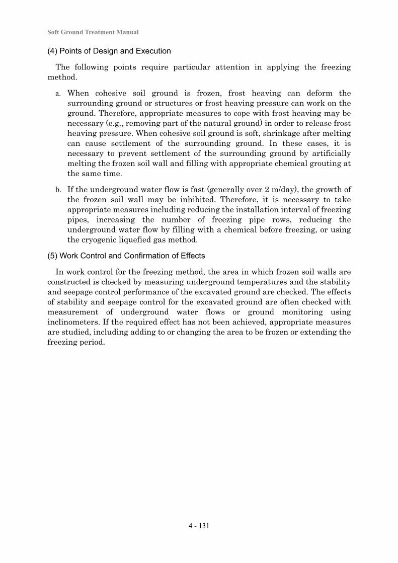
Soft Ground Treatment Manual
4 - 131
(4) Points of Design and Execution
The following points require particular attention in applying the freezing method.
a. When cohesive soil ground is frozen, frost heaving can deform the surrounding ground or structures or frost heaving pressure can work on the ground. Therefore, appropriate measures to cope with frost heaving may be necessary (e.g., removing part of the natural ground) in order to release frost heaving pressure. When cohesive soil ground is soft, shrinkage after melting can cause settlement of the surrounding ground. In these cases, it is necessary to prevent settlement of the surrounding ground by artificially melting the frozen soil wall and filling with appropriate chemical grouting at the same time.
b. If the underground water flow is fast (generally over 2 m/day), the growth of the frozen soil wall may be inhibited. Therefore, it is necessary to take appropriate measures including reducing the installation interval of freezing pipes, increasing the number of freezing pipe rows, reducing the underground water flow by filling with a chemical before freezing, or using the cryogenic liquefied gas method.
(5) Work Control and Confirmation of Effects
In work control for the freezing method, the area in which frozen soil walls are constructed is checked by measuring underground temperatures and the stability and seepage control performance of the excavated ground are checked. The effects of stability and seepage control for the excavated ground are often checked with measurement of underground water flows or ground monitoring using inclinometers. If the required effect has not been achieved, appropriate measures are studied, including adding to or changing the area to be frozen or extending the freezing period.
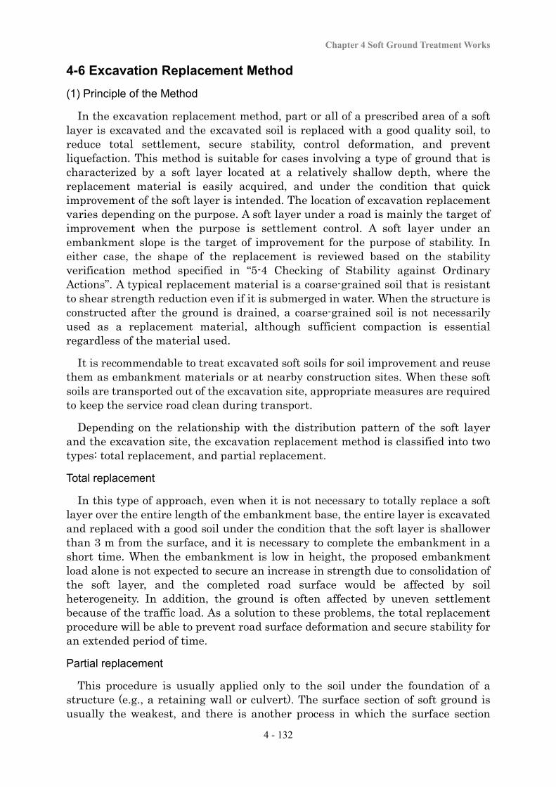
Chapter 4 Soft Ground Treatment Works
4 - 132
4-6 Excavation Replacement Method
(1) Principle of the Method
In the excavation replacement method, part or all of a prescribed area of a soft layer is excavated and the excavated soil is replaced with a good quality soil, to reduce total settlement, secure stability, control deformation, and prevent liquefaction. This method is suitable for cases involving a type of ground that is characterized by a soft layer located at a relatively shallow depth, where the replacement material is easily acquired, and under the condition that quick improvement of the soft layer is intended. The location of excavation replacement varies depending on the purpose. A soft layer under a road is mainly the target of improvement when the purpose is settlement control. A soft layer under an embankment slope is the target of improvement for the purpose of stability. In either case, the shape of the replacement is reviewed based on the stability verification method specified in “5-4 Checking of Stability against Ordinary Actions”. A typical replacement material is a coarse-grained soil that is resistant to shear strength reduction even if it is submerged in water. When the structure is constructed after the ground is drained, a coarse-grained soil is not necessarily used as a replacement material, although sufficient compaction is essential regardless of the material used.
It is recommendable to treat excavated soft soils for soil improvement and reuse them as embankment materials or at nearby construction sites. When these soft soils are transported out of the excavation site, appropriate measures are required to keep the service road clean during transport.
Depending on the relationship with the distribution pattern of the soft layer and the excavation site, the excavation replacement method is classified into two types: total replacement, and partial replacement.
Total replacement
In this type of approach, even when it is not necessary to totally replace a soft layer over the entire length of the embankment base, the entire layer is excavated and replaced with a good soil under the condition that the soft layer is shallower than 3 m from the surface, and it is necessary to complete the embankment in a short time. When the embankment is low in height, the proposed embankment load alone is not expected to secure an increase in strength due to consolidation of the soft layer, and the completed road surface would be affected by soil heterogeneity. In addition, the ground is often affected by uneven settlement because of the traffic load. As a solution to these problems, the total replacement procedure will be able to prevent road surface deformation and secure stability for an extended period of time.
Partial replacement
This procedure is usually applied only to the soil under the foundation of a structure (e.g., a retaining wall or culvert). The surface section of soft ground is usually the weakest, and there is another process in which the surface section
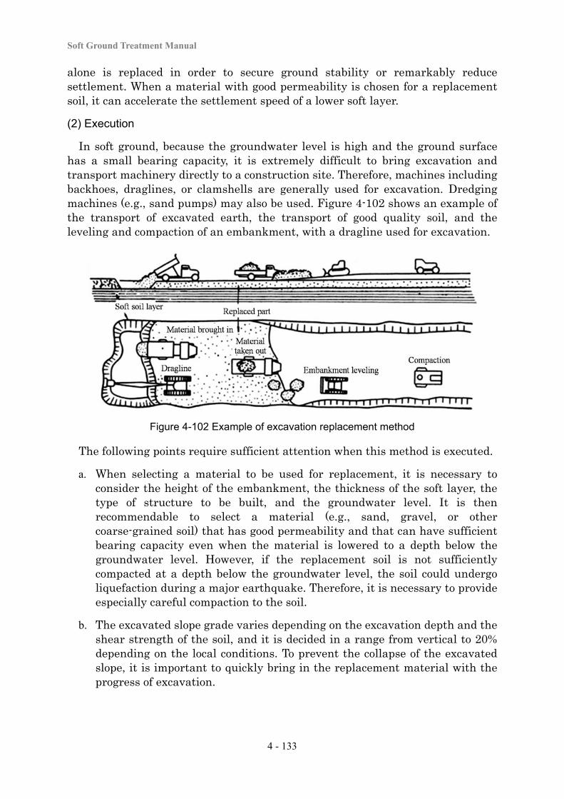
Soft Ground Treatment Manual
4 - 133
alone is replaced in order to secure ground stability or remarkably reduce settlement. When a material with good permeability is chosen for a replacement soil, it can accelerate the settlement speed of a lower soft layer.
(2) Execution
In soft ground, because the groundwater level is high and the ground surface has a small bearing capacity, it is extremely difficult to bring excavation and transport machinery directly to a construction site. Therefore, machines including backhoes, draglines, or clamshells are generally used for excavation. Dredging machines (e.g., sand pumps) may also be used. Figure 4-102 shows an example of the transport of excavated earth, the transport of good quality soil, and the leveling and compaction of an embankment, with a dragline used for excavation.
Figure 4-102 Example of excavation replacement method
The following points require sufficient attention when this method is executed.
a. When selecting a material to be used for replacement, it is necessary to consider the height of the embankment, the thickness of the soft layer, the type of structure to be built, and the groundwater level. It is then recommendable to select a material (e.g., sand, gravel, or other coarse-grained soil) that has good permeability and that can have sufficient bearing capacity even when the material is lowered to a depth below the groundwater level. However, if the replacement soil is not sufficiently compacted at a depth below the groundwater level, the soil could undergo liquefaction during a major earthquake. Therefore, it is necessary to provide especially careful compaction to the soil.
b. The excavated slope grade varies depending on the excavation depth and the shear strength of the soil, and it is decided in a range from vertical to 20% depending on the local conditions. To prevent the collapse of the excavated slope, it is important to quickly bring in the replacement material with the progress of excavation.
Chapter 4 Soft Ground Treatment Works
4 - 134
(3) Work Control
Work control with the excavation replacement method involves selecting materials that satisfy the prescribed quality requirements (grain distribution or field density of the replacement soil) and periodically implementing sampling tests. During execution, it also involves implementing field density testing of the replacement material at an appropriate frequency and workmanship control for the improvement width or thickness.
(4) Confirmation of Effects
The effects of this method are generally checked by measuring settlement reduction and stability control.
Reduction in settlement and securing stability
Settlement reduction and stability control are checked by ground monitoring of settlement and other changes of the embankment. The ground monitoring procedure is as provided in “Chapter 5: Work Control and Maintenance”. If the desired improvement effect has not been achieved, the cause of failure is investigated, and appropriate measures are taken, including a review of the replacement soil or the use of other methods.
Liquefaction control
For the effect of liquefaction control, soil replacement is conducted with experimental construction, and the status of compaction is checked by sounding. If the intended effect cannot be obtained, appropriate measures are studied, including changing the compaction method or replacement soil.
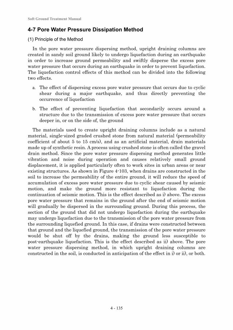
Soft Ground Treatment Manual
4 - 135
4-7 Pore Water Pressure Dissipation Method
(1) Principle of the Method
In the pore water pressure dispersing method, upright draining columns are created in sandy soil ground likely to undergo liquefaction during an earthquake in order to increase ground permeability and swiftly disperse the excess pore water pressure that occurs during an earthquake in order to prevent liquefaction. The liquefaction control effects of this method can be divided into the following two effects.
a. The effect of dispersing excess pore water pressure that occurs due to cyclic shear during a major earthquake, and thus directly preventing the occurrence of liquefaction
b. The effect of preventing liquefaction that secondarily occurs around a structure due to the transmission of excess pore water pressure that occurs deeper in, or on the side of, the ground
The materials used to create upright draining columns include as a natural material, single-sized graded crushed stone from natural material (permeability coefficient of about 5 to 15 cm/s), and as an artificial material, drain materials made up of synthetic resin. A process using crushed stone is often called the gravel drain method. Since the pore water pressure dispersing method generates little vibration and noise during operation and causes relatively small ground displacement, it is applied particularly often to work sites in urban areas or near existing structures. As shown in Figure 4-103, when drains are constructed in the soil to increase the permeability of the entire ground, it will reduce the speed of accumulation of excess pore water pressure due to cyclic shear caused by seismic motion, and make the ground more resistant to liquefaction during the continuation of seismic motion. This is the effect described as i) above. The excess pore water pressure that remains in the ground after the end of seismic motion will gradually be dispersed in the surrounding ground. During this process, the section of the ground that did not undergo liquefaction during the earthquake may undergo liquefaction due to the transmission of the pore water pressure from the surrounding liquefied ground. In this case, if drains were constructed between that ground and the liquefied ground, the transmission of the pore water pressure would be shut off by the drains, making the ground less susceptible to post-earthquake liquefaction. This is the effect described as ii) above. The pore water pressure dispersing method, in which upright draining columns are constructed in the soil, is conducted in anticipation of the effect in i) or ii), or both.
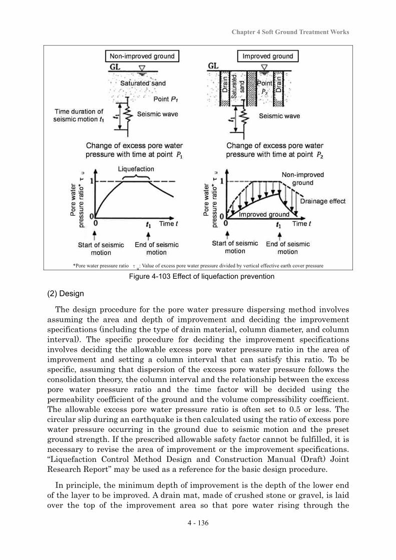
Chapter 4 Soft Ground Treatment Works
4 - 136
*Pore water pressure ratio τ : Value of excess pore water pressure divided by vertical effective earth cover pressure Figure 4-103 Effect of liquefaction prevention
(2) Design
The design procedure for the pore water pressure dispersing method involves assuming the area and depth of improvement and deciding the improvement specifications (including the type of drain material, column diameter, and column interval). The specific procedure for deciding the improvement specifications involves deciding the allowable excess pore water pressure ratio in the area of improvement and setting a column interval that can satisfy this ratio. To be specific, assuming that dispersion of the excess pore water pressure follows the consolidation theory, the column interval and the relationship between the excess pore water pressure ratio and the time factor will be decided using the permeability coefficient of the ground and the volume compressibility coefficient. The allowable excess pore water pressure ratio is often set to 0.5 or less. The circular slip during an earthquake is then calculated using the ratio of excess pore water pressure occurring in the ground due to seismic motion and the preset ground strength. If the prescribed allowable safety factor cannot be fulfilled, it is necessary to revise the area of improvement or the improvement specifications. “Liquefaction Control Method Design and Construction Manual (Draft) Joint Research Report” may be used as a reference for the basic design procedure.
In principle, the minimum depth of improvement is the depth of the lower end of the layer to be improved. A drain mat, made of crushed stone or gravel, is laid over the top of the improvement area so that pore water rising through the
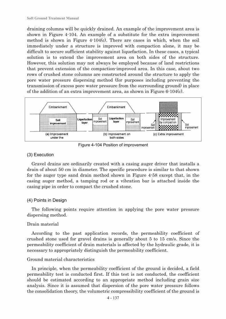
Soft Ground Treatment Manual
4 - 137
draining columns will be quickly drained. An example of the improvement area is shown in Figure 4-104. An example of a substitute for the extra improvement method is shown in Figure 4-104(c). There are cases in which, when the soil immediately under a structure is improved with compaction alone, it may be difficult to secure sufficient stability against liquefaction. In these cases, a typical solution is to extend the improvement area on both sides of the structure. However, this solution may not always be employed because of land restrictions that prevent extension of the compaction-improved area. In this case, about two rows of crushed stone columns are constructed around the structure to apply the pore water pressure dispersing method (for purposes including preventing the transmission of excess pore water pressure from the surrounding ground) in place of the addition of an extra improvement area, as shown in Figure 6-104(c).
Figure 4-104 Position of improvement
(3) Execution
Gravel drains are ordinarily created with a casing auger driver that installs a drain of about 50 cm in diameter. The specific procedure is similar to that shown for the auger type sand drain method shown in Figure 4-58 except that, in the casing auger method, a tamping rod or a vibration bar is attached inside the casing pipe in order to compact the crushed stone.
(4) Points in Design
The following points require attention in applying the pore water pressure dispersing method.
Drain material
According to the past application records, the permeability coefficient of crushed stone used for gravel drains is generally about 5 to 15 cm/s. Since the permeability coefficient of drain materials is affected by the hydraulic grade, it is necessary to appropriately distinguish the permeability coefficient.
Ground material characteristics
In principle, when the permeability coefficient of the ground is decided, a field permeability test is conducted first. If this test is not conducted, the coefficient should be estimated according to an appropriate method including grain size analysis. Since it is assumed that dispersion of the pore water pressure follows the consolidation theory, the volumetric compressibility coefficient of the ground is
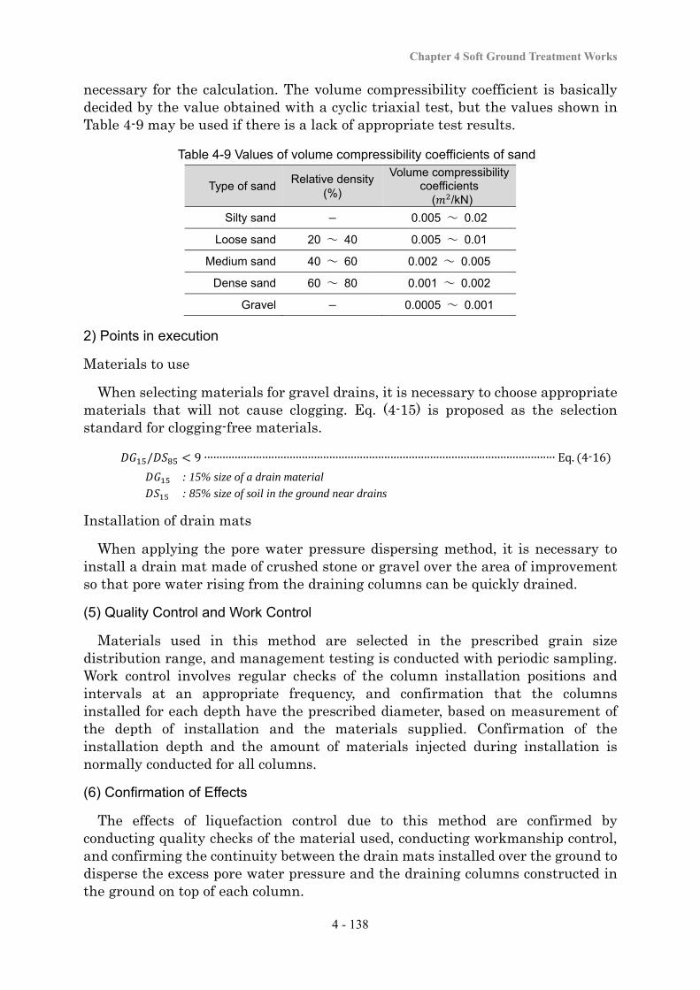
Chapter 4 Soft Ground Treatment Works
4 - 138
necessary for the calculation. The volume compressibility coefficient is basically decided by the value obtained with a cyclic triaxial test, but the values shown in Table 4-9 may be used if there is a lack of appropriate test results.
Table 4-9 Values of volume compressibility coefficients of sand
Type of sand Relative density
(%)
Volume compressibility coefficients ( /kN)
Silty sand 0.005 ~ 0.02
Loose sand 20 ~ 40 0.005 ~ 0.01
Medium sand 40 ~ 60 0.002 ~ 0.005
Dense sand 60 ~ 80 0.001 ~ 0.002
Gravel 0.0005 ~ 0.001
2) Points in execution
Materials to use
When selecting materials for gravel drains, it is necessary to choose appropriate materials that will not cause clogging. Eq. (4-15) is proposed as the selection standard for clogging-free materials.
/ 9 ∙∙∙∙∙∙∙∙∙∙∙∙∙∙∙∙∙∙∙∙∙∙∙∙∙∙∙∙∙∙∙∙∙∙∙∙∙∙∙∙∙∙∙∙∙∙∙∙∙∙∙∙∙∙∙∙∙∙∙∙∙∙∙∙∙∙∙∙∙∙∙∙∙∙∙∙∙∙∙∙∙∙∙∙∙∙∙∙∙∙∙∙∙∙∙∙∙∙∙∙∙∙∙∙∙∙∙∙∙∙∙∙∙∙∙ Eq. 4-16
: 15% size of a drain material
: 85% size of soil in the ground near drains
Installation of drain mats
When applying the pore water pressure dispersing method, it is necessary to install a drain mat made of crushed stone or gravel over the area of improvement so that pore water rising from the draining columns can be quickly drained.
(5) Quality Control and Work Control
Materials used in this method are selected in the prescribed grain size distribution range, and management testing is conducted with periodic sampling. Work control involves regular checks of the column installation positions and intervals at an appropriate frequency, and confirmation that the columns installed for each depth have the prescribed diameter, based on measurement of the depth of installation and the materials supplied. Confirmation of the installation depth and the amount of materials injected during installation is normally conducted for all columns.
(6) Confirmation of Effects
The effects of liquefaction control due to this method are confirmed by conducting quality checks of the material used, conducting workmanship control, and confirming the continuity between the drain mats installed over the ground to disperse the excess pore water pressure and the draining columns constructed in the ground on top of each column.
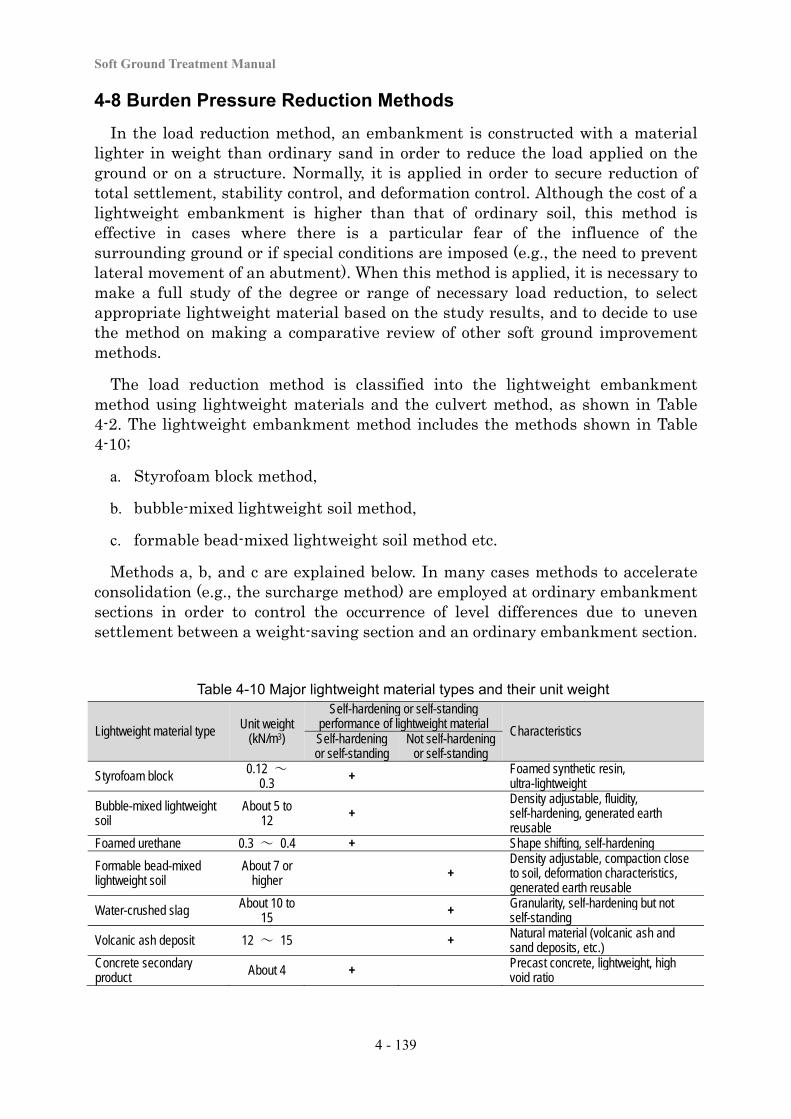
Soft Ground Treatment Manual
4 - 139
4-8 Burden Pressure Reduction Methods
In the load reduction method, an embankment is constructed with a material lighter in weight than ordinary sand in order to reduce the load applied on the ground or on a structure. Normally, it is applied in order to secure reduction of total settlement, stability control, and deformation control. Although the cost of a lightweight embankment is higher than that of ordinary soil, this method is effective in cases where there is a particular fear of the influence of the surrounding ground or if special conditions are imposed (e.g., the need to prevent lateral movement of an abutment). When this method is applied, it is necessary to make a full study of the degree or range of necessary load reduction, to select appropriate lightweight material based on the study results, and to decide to use the method on making a comparative review of other soft ground improvement methods.
The load reduction method is classified into the lightweight embankment method using lightweight materials and the culvert method, as shown in Table 4-2. The lightweight embankment method includes the methods shown in Table 4-10;
a. Styrofoam block method,
b. bubble-mixed lightweight soil method,
c. formable bead-mixed lightweight soil method etc.
Methods a, b, and c are explained below. In many cases methods to accelerate consolidation (e.g., the surcharge method) are employed at ordinary embankment sections in order to control the occurrence of level differences due to uneven settlement between a weight-saving section and an ordinary embankment section.
Table 4-10 Major lightweight material types and their unit weight
Lightweight material type Unit weight (kN/m3)
Self-hardening or self-standing performance of lightweight material Characteristics Self-hardening or self-standing
Not self-hardening or self-standing
Styrofoam block 0.12 ~ 0.3 + Foamed synthetic resin,
ultra-lightweight
Bubble-mixed lightweight soil
About 5 to 12 +
Density adjustable, fluidity, self-hardening, generated earth reusable
Foamed urethane 0.3 ~ 0.4 + Shape shifting, self-hardening
Formable bead-mixed lightweight soil
About 7 or higher +
Density adjustable, compaction close to soil, deformation characteristics, generated earth reusable
Water-crushed slag About 10 to 15 + Granularity, self-hardening but not
self-standing
Volcanic ash deposit 12 ~ 15 + Natural material (volcanic ash and sand deposits, etc.)
Concrete secondary product About 4 + Precast concrete, lightweight, high
void ratio
Chapter 4 Soft Ground Treatment Works
4 - 140
4-8-1 Styrofoam Blocks Method
(1) Principle of the Method
The Styrofoam block method is conducted in order to reduce total settlement, secure stability, and prevent deformation. In this method, Styrofoam blocks, each typically measuring 2 m × 1 m × 0.5 m, are piled by interconnecting them to construct an embankment. Since Styrofoam blocks are highly lightweight (unit weight of 0.12 to 0.30 kN/m3), they can be piled by manual labor. They are also self-standing. Because of these characteristics, this method is often applied to the following sites where a soil-made embankment may cause problems.
a. As an embankment can be quickly built up with this method, it is used when an embankment needs to be constructed in a short time.
b. This method is implemented using manual labor at sites with extremely soft soils that seriously lack trafficability, or at narrow spaces where large construction machines cannot enter.
c. This method is used as a solution for reducing earth pressure for structures that receive eccentric earth pressure (e.g., abutments or retaining walls).
d. This method is used for embankments (retaining walls) having vertical slope surfaces because of plain protective walls.
(2) Design
The design procedure for this method involves identifying design conditions (e.g., the design load at a work site) or ground conditions and reviewing the inner and outer section stability of the Styrofoam blocks. For inner section stability, the loads applied to the Styrofoam blocks due to the pavement, preloading, or traffic load are checked to confirm that they are below the allowable unit stress. For outer section stability, a study is conducted to confirm safety with respect to ground settlement or ground slip failure for the entire embankment including the Styrofoam blocks. In addition, since Styrofoam blocks are ultra-lightweight, it is necessary to study uplift of the ground due to groundwater or the possible occurrence of ground liquefaction.
It is recommendable to plan the use of Styrofoam blocks at sites that are not influenced by earth pressure due to the natural ground or due to sediment fills in the back. Because they are ultra-lightweight, Styrofoam blocks could suffer sliding or other problems when affected by earth pressure from the natural ground in the back. Thus, when there is natural ground or an embankment in the back, it is necessary to study providing a stable gradient for the blocks to be self-standing or constructing an embankment in front of the Styrofoam blocks.
(3) Execution
The work procedure for this method involves leveling the formation level, where Styrofoam blocks are proposed to be installed (e.g., by laying sand mats to create a level surface), installing the Styrofoam blocks flat without causing any level
Soft Ground Treatment Manual
4 - 141
differences, fixing the blocks with metal fasteners, providing a transition section between the Styrofoam block installation and the ordinary embankment section, and constructing concrete slabs over the Styrofoam blocks after installing them.
(4) Points of Design and Execution
The following points require attention when this method is applied.
Fire prevention
In principle, flameproof Styrofoam blocks are used. If non-flameproof Styrofoam blocks are used, sufficient measures are taken in the design as precautions (including providing a protective wall or sufficient soil cover thickness) so that the Styrofoam blocks will not be damaged by vehicle fires or slope fires during road service period. It is also necessary to take anti-fire measures during the works.
Chemicals
Styrofoam blocks are generally resistant to acid or alkali but weak against aromatic hydrocarbons, halogen hydrocarbons, ketones, esters, and other petroleum-based chemicals. It is necessary to bear in mind that these substances are also contained in gasoline and organic solvents, as well as in many kinds of paints, adhesives, and cleaning agents. Light oils, animal and vegetable oils, paraffin, and lanolin also require attention, as they will corrode Styrofoam surfaces in the long term.
Ultraviolet radiation
Styrofoam blocks are degraded by exposure to ultraviolet radiation. Therefore, even during the works, it is necessary to take appropriate precautions (e.g., covering them with sheets) to prevent them from being exposed to direct sunlight for a long time.
Uplift and wind
Since Styrofoam blocks are ultra-lightweight, they can be lifted up by the influence of groundwater or scattered by strong wind. To avoid these problems, as a general rule Styrofoam blocks are not installed at a depth below the groundwater level, and careful measures are taken to secure good drainage around the embankment. Necessary measures during the works or storage also include placing weights on the blocks or covering them with net sheets to keep them together in the face of strong wind.
Uneven settlement
Where serious settlement is expected to occur or uneven settlement occurs, the blocks may be dislocated from each other or internal stress may occur in the blocks. A solution to these cases is the combined use of the surcharge method or other consolidation acceleration procedures, or the replacement method. Another solution is to excavate and replace the soil with Styrofoam blocks in order to minimize or eliminate the new addition of loads due to the embankment. In this case, it is necessary to bear in mind uplift due to groundwater.
Chapter 4 Soft Ground Treatment Works
4 - 142
(5) Quality Control and Work Control
Quality control for Styrofoam blocks involves selecting appropriate materials that satisfy the prescribed quality and implementing unit weight tests of the Styrofoam blocks in advance. Work control during the execution stage for the Styrofoam block method involves;
a. confirming the flatness of the formation level,
b. measuring the level difference for every installation of blocks, and
c. confirming the workmanship of the Styrofoam block embankment.
(6) Confirmation of Effects
The effects of settlement and slip sliding force reduction are often checked with ground monitoring of embankment settlement after the completion of embankment. The ground monitoring procedure explained in “Chapter 5: Work Control and Maintenance” is used. If the prescribed effect has not been achieved, appropriate measures are studied, including the additional implementation of soft ground treatment measures (e.g., the compaction method or induration method).
4-8-2 Bubble Mixed Lightweight Soil Method
(1) Principle of the Method
The bubble-mixed lightweight soil method is conducted for the purposes of reducing total settlement, stability control, and preventing deformation. In this method, embankments are constructed using bubble-mixed lightweight soils made up of fluidized soil (soil mixed with a stabilizer like cement and fluidized) and foam or foamed mortar composed of mortar made up of fine aggregate instead of soil and mixed with foam. In this method, an arbitrary level of strength ( = about 500 to 1,000 kN/m2) or unit weight ( = about 5 to 12 kN/m3) can be set by adjusting the amount of cement or foam, and it has advantages including excellent fluidity, self-hardening properties, and the ability to use locally generated earth. Moreover, because it is self-standing, embankments with upright walls can be constructed. Generation of noise and vibration during construction works are also exceedingly low with this method. For its lightness, fluidity, self-hardening properties, and self-standing capability, this method is often applied to the following locations where soil embankments cause problems.
a. Small or narrow places where large construction machines for leveling or compaction cannot gain access
b. Locations treated with backfill (e.g., for abutments or retaining walls) as a solution to earth pressure reduction for structures that receive eccentric earth pressure
Soft Ground Treatment Manual
4 - 143
(2) Design
The design procedure for the bubble-mixed lightweight soil method involves;
a. identifying the conditions necessary for the design (e.g., the loading conditions and ground conditions at the work site),
b. deciding the area of soil to be improved by the bubble-mixed lightweight soil or the target density or the strength of improvement,
c. reviewing inner and outer section stability in the same way as in the Styrofoam block method, and
d. deciding the mix design.
When the original ground is excavated and replaced with the bubble-mixed lightweight soil and uplift of the ground due to a rise of the groundwater level or a rise of the water level due to a flood is considered likely, it is also necessary to study uplift. It is recommendable to plan the use of bubble-mixed lightweight soil in locations that are free from the influence of earth pressure due to the natural ground or sediment filling in the rear. It is necessary to study applying the method at a stable gradient so that the rear embankment can stand alone, constructing another embankment in the front, etc.
(3) Execution
The work procedure for the bubble-mixed lightweight soil method involves;
a. excavating and preparing the site where the bubble-mixed lightweight soil is to be used,
b. installing forms,
c. producing the bubble-mixed lightweight soil in a mixing plant, and
d. pouring the produced soil with a grouting pump.
When the soil is poured, the thickness of each pouring is less than about 1 m to prevent sinking due to loss of foam after pouring. The forms are removed after the passage of the prescribed curing period. When the soil is filled to a necessary height, paving and other work are conducted.
It is necessary to change the production flow depending on the type of soil when a bubble-mixed lightweight soil is produced. In general, two types of materials are used: cohesive soil that requires soil particle adjustment, and sandy soil that can directly be inserted into a mixer. For cohesive soil, water is added to the cohesive soil for particle adjustment, the wet density is adjusted, and an adjusted soil is prepared. This adjusted soil is mixed with a stabilizer and foam to produce a bubble-mixed lightweight soil. For sandy soil, sand, water, and stabilizer are mixed in a mixing plant and foam is added for mixing. The mixing ratio is decided according to a field mixing test to secure the prescribed density and strength. Because cement or cement-based stabilizer is used, a specimen is prepared using
Chapter 4 Soft Ground Treatment Works
4 - 144
the decided mix proportions and hexavalent chromium elution testing is conducted.
(4) Points of Design and Execution
The following points require attention when applying this method.
Uneven settlement
Where serious settlement is expected to occur or uneven settlement occurs, it is necessary to use a combination with a consolidation acceleration method (e.g., the surcharge method) and to provide a joint-sealing material in the lightweight soil embankment to make it capable of following the movement of settlement.
Prevention of water infiltration into the lightweight soil embankment
When the bubble-mixed lightweight soil absorbs rainwater or groundwater, its wet density increases and it becomes heavier, and it can even lose its strength. In addition, when water collects in the bottom or at the back of the embankment, it will reduce stability due to buoyancy or water pressure. Therefore, it is essential to prevent rainwater infiltration into the embankment with water cut-off sheets or the like and to provide groundwater drainage.
Loss of foam
Part of the foam disappears during mixing of the cement slurry and foam, during pressure feeding, or due to rainfall during or immediately after placement. This loss of foam can cause degradation of the soil quality. Therefore, it is important to conduct appropriate work control including the additional supply of foam as necessary.
Prevention of cracking
A lightweight soil embankment may suffer cracking due to heat generation during hardening (the temperature can go up to 100˚C) or drying. Once cracks occur, groundwater or rainwater can easily enter the soil through the cracks. Therefore, it is necessary to take appropriate measures to prevent cracking by, for example, appropriately laying wire nets or protecting the soil with sheets for curing and protection.
(5) Quality Control and Work Control
Quality control and work control procedures for the bubble-mixed lightweight soil method involve weighing each component material at the mixing plant and measuring the flow value, which is one of the indexes of fluidity, wet density after curing, unconfined compression strength, and other parameters. It is also necessary to confirm the workmanship of the embankment completed with the bubble-mixed lightweight soil.

Soft Ground Treatment Manual
4 - 145
(6) Confirmation of Effects
The procedure for the confirmation of effects is the same as that for “4-8-1 Styrofoam Block Method”.
4-8-3 Formable Beads Mixed Lightweight Soil Method
(1) Principle of the Method
The embankment method using formable bead-mixed lightweight soil is conducted for the purposes of reducing total settlement, controlling stability, and preventing deformation. Composed of soil material mixed with formable beads, a formable bead-mixed lightweight soil has a number of advantages including lightness in weight and a capability to follow deformation similar to that of ordinary soil. Cement or other materials may be added to compensate for the strength reduction produced due to its being lightweight. The characteristics of formable bead-mixed lightweight soil greatly vary depending on the type of soil used as a raw material, the mixing ratio of the formable beads, and the addition of stabilizer. To the extent that design and execution are conducted within the prescribed range, it can be handled just like ordinary soil.
Normally, an ordinary soil type is used, in a mixture composed of a soil with natural water content, formable beads, and a stabilizer. When a cohesive soil with high water content, a volcanic cohesive soil, or a muddy soil is used, it should be treated in a muddy state after being mixed with water.
Materials used to produce formable beads include particles of styrene resins or other resins foamed to 1 to 10 mm in diameter or pulverized foamed moldings. Portland cement is usually used as a stabilizer. Uniform mixing of a soil, beads, and a stabilizer is generally conducted with a batch plant, consisting of a mixer, material weigher, and supplier, or an in-situ mixing machine. For the construction of embankments, spreading and rolling with a wet bulldozer can be used for an ordinary soil type, while a muddy slurry soil type is flowed into forms in the same way as a bubble-mixed lightweight soil.
(2) Design
The design procedure for an embankment with a formable bead-mixed lightweight soil involves setting the density and strength of the formable bead-mixed lightweight soil in the prescribed range of values, and studying the circular slip, bearing capacity, and settlement in the same way as ordinary sediments. The density of the formable bead-mixed lightweight soil, which is normally adjusted by changing the mixing amount of formable beads, can be adjusted in a range from 8.0 to 15.0 kN/m3 in wet density. In practice, the wet density is often set to over 10.5 kN/m3 because of the buoyancy problem. The strength of the formable bead-mixed lightweight soil is normally adjusted by changing the addition of stabilizer. In practice, for application as a soil material,
Chapter 4 Soft Ground Treatment Works
4 - 146
the soil is often adjusted in a range from 50 to 300 kN/m2 in unconfined compressive strength.
The strength constant of the formable bead-mixed lightweight soil is treated as a cohesive soil when the unconfined compression test can be performed, and cohesive force c is set to half the unconfined compressive strength . The target strength in the mixing test is often set to twice or three times greater than the strength required in the design by taking into account the occurrence of variation in field works. If an unconfined compression test cannot be conducted because of the low strength or because c and are necessary as strength constants, the target strength is calculated from a triaxial compression test. In order to maintain the desired density or strength of the formable bead-mixed lightweight soil, the formable bead volumetric mixing ratio and the addition of stabilizer are set from a laboratory mixing test.
(3) Execution
In constructing an embankment using a formable bead-mixed lightweight soil, the work procedure for an ordinary soil type is described here, as the procedure for bubble-mixed lightweight soil is applied to that for the slurry type. Formable beads are generally mixed in two ways: plant mixing and in-situ mixing.
For plant mixing,
a. necessary materials are put in the mixer in the order of formable beads, water and a stabilizer, and finally the material soil;
b. after these materials are mixed in the plant, the mixture is transported to a construction site in dump trucks, spread and compacted in situ, and cured.
For in-situ mixing,
a. a mixing yard is first set up at the construction site;
b. a stabilizer, formable beads, and water are spread over a designated area at the site and stirred and mixed using a backhoe; and
c. the mixed materials are then excavated and transported in a dump truck to the embankment location, where the materials are spread, roller-compacted, and cured.
In order to maintain the desired density and strength, a mixing test and rolling test are conducted on-site. The mixing test checks the formable bead volumetric mixing ratio and the addition of stabilizer, while the rolling test checks the spreading depth and the number of passes.
(4) Points of Design and Execution
The following points require particular attention in applying this method.
Soft Ground Treatment Manual
4 - 147
Control of scattering of formable beads during mixing
During plant mixing, the process of putting the beads into the plant requires the most caution regarding scattering. It is recommendable to conduct the operation in a tightly closed space using a continuous transport process with an automatic weighing capability. During in-situ mixing, stabilizers and formable beads are both exposed to the air and are highly likely to be scattered by wind. A solution to this is the installation of anti-wind sheets or avoiding working during a strong wind.
Preventing scattering of beads during transport or after rolling compaction
It is necessary to take precautions not to allow beads to scatter during transport (e.g., by covering the bed with sheets). After rolling compaction, it is necessary to cover and cure the embankment with protective sheets.
(5) Quality Control and Work Control
The quality control and work control procedures for formable bead-mixed lightweight soils involve;
a. weighing the material soil, formable beads, and stabilizers,
b. mixing these materials in their respective prescribed quantities,
c. measuring the water content, density, and strength of the soil,
d. implementing in-situ density tests or cone penetration tests at the rolling compaction site, and
e. confirming the workmanship of the embankment during roller compaction.
(6) Confirmation of Effects
The procedure for the confirmation of effects is the same as that for “4-8-1 Styrofoam Blocks Method”.
4-8-4 Culvert Method
(1) Principle of the Method
The culvert method is conducted as a substitute for an embankment material for purposes including reducing total settlement, controlling stability, and preventing deformation. In this method, culverts are constructed in series to construct a structural body that is light in weight and that can respond to the behavior of the ground. This method may also be used to reduce the load on the back of an existing abutment that has suffered displacement. When applied to a newly constructed structure, the surcharge method may be used to reinforce the foundation ground for the culvert method.
(2) Design
The design procedure for the culvert method involves clarifying the conditions necessary for the design, including the loading conditions at the work site (burden

Chapter 4 Soft Ground Treatment Works
4 - 148
loads, earth pressure of the natural ground behind the site, traffic loads, working loads, buoyancy, seismic loads, and other shock loads), and the ground conditions (soil properties, bearing capacity, strength, groundwater, or spring water), deciding the apparent unit weight necessary for the design, and deciding the shape, number and layout of the culverts. See “Road Earthworks: Culvert Work Guidelines” for the detailed culvert design and work procedures.
(3) Points of Execution
One of the major points to note about the use of this method is uneven settlement in the longitudinal direction. It is necessary to sufficiently study the ground conditions prior to applying this method.
(4) Quality Control and Work Control
Quality control involves selecting appropriate materials that satisfy the prescribed quality. In addition, appropriate work control is conducted.
(5) Confirmation of Effects
The procedure for the confirmation of effects is the same as that for “4-8-1 Styrofoam Blocks Method”.

Soft Ground Treatment Manual
4 - 149
4-9 Reinforcement Banking Method
(1) Principle of the Method
In the embankment reinforcement method, reinforcing materials are installed on the surface of the foundation ground or in the lower part of the embankment to integrate the reinforcing materials and the embankment as a single mass, restraining the spread of the bottom of the embankment accelerated by the lateral movement of the ground, with the goal of securing the stability of the embankment, as shown in Figure 4-105. When a soft soil layer is thin or settlement of the entire embankment may be allowed to some extent, in many cases the embankment reinforcement method alone is used. When a soft layer is thick or the embankment is high, it may be used as an auxiliary method for other methods (e.g., the deep mixed method).
Figure 4-105 Concept of the embankment reinforcement method
The embankment reinforcement method is categorized into the geotextile method and wire net method according to the type of reinforcing material. The geotextile method uses sheet-shaped materials having high tensile strength. The wire net method uses steel nets, hoop steel, or other shapes. Materials with various strength and deformation characteristics have been developed as reinforcing materials, and it is necessary to make a full study of their friction characteristics or maximum tensile strength and other factors, as well as a study of the soil, before deciding to use the embankment reinforcement method.
Since this method is inexpensive, in many cases it is used as an auxiliary measure with other methods. It is capable of controlling the slack of the embankment material induced due to consolidation settlement and is also expected to control embankment deformation if the embankment material or the foundation ground is liquefied due to a major earthquake.
(2) Design
In the design procedure for the geotextile method, the failure modes to consider are classified into the following, as shown in Figure 4-106 and studies should be performed for each of these situations.
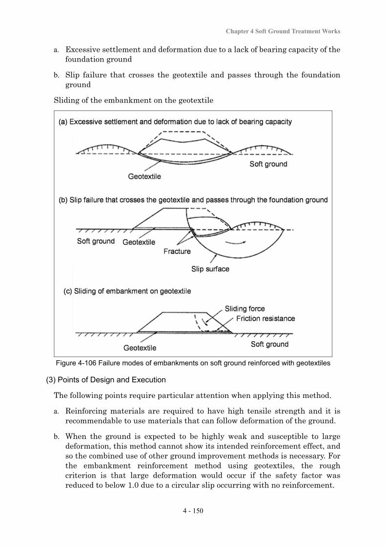
Chapter 4 Soft Ground Treatment Works
4 - 150
a. Excessive settlement and deformation due to a lack of bearing capacity of the foundation ground
b. Slip failure that crosses the geotextile and passes through the foundation ground
Sliding of the embankment on the geotextile
Figure 4-106 Failure modes of embankments on soft ground reinforced with geotextiles
(3) Points of Design and Execution
The following points require particular attention when applying this method.
a. Reinforcing materials are required to have high tensile strength and it is recommendable to use materials that can follow deformation of the ground.
b. When the ground is expected to be highly weak and susceptible to large deformation, this method cannot show its intended reinforcement effect, and so the combined use of other ground improvement methods is necessary. For the embankment reinforcement method using geotextiles, the rough criterion is that large deformation would occur if the safety factor was reduced to below 1.0 due to a circular slip occurring with no reinforcement.
Soft Ground Treatment Manual
4 - 151
c. Since the design tensile strength per reinforcing material is limited, when the desired tensile strength is large or large resistance against the sliding force of the embankment is necessary, two or more reinforcing materials are required.
d. Reinforcing materials can deteriorate depending on the environmental conditions (e.g., the chemical components in the soil). When a gravelly soil is used for an embankment material, it may harm the reinforcing material. Therefore, it is necessary to carry out the design and execution with full consideration of the impacts of these environmental conditions.
e. For the embankment procedure, the reinforcing material is tensed to make it free of slack and the slope surface of the embankment is filled ahead of other portions.
f. It is necessary to compact the embankment material around the reinforcing material in order to integrate the embankment and the reinforcing material and increase the anchoring effect of the embankment itself.
g. Construction machines having contact pressure that is as small as possible are used, and sufficient compaction is provided to the material.
(4) Quality Control and Work Control
The quality control and work control procedures involve;
a. selecting materials that satisfy the prescribed quality for embankment or reinforcing materials,
b. appropriately installing reinforcing materials (installation interval and position), and
c. appropriately managing embankment compaction for integration with the embankment.
(5) Confirmation of Effects
The effects of an increase in embankment stability are often measured with ground monitoring of settlement or deformation after the completion of embankment. The ground monitoring procedure is specified in “Chapter 5: Work Control and Maintenance”. If the desired effect has not been achieved, appropriate measures are taken including leaving the embankment for a period of time in order to accelerate consolidation.
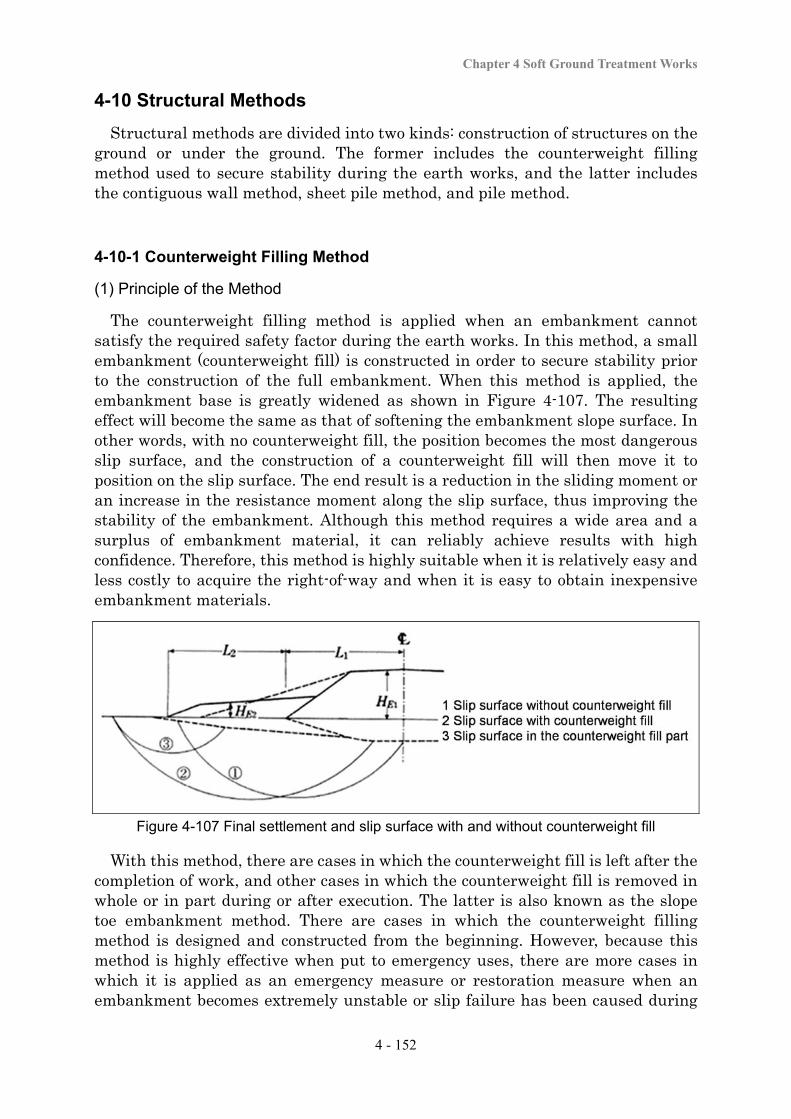
Chapter 4 Soft Ground Treatment Works
4 - 152
4-10 Structural Methods
Structural methods are divided into two kinds: construction of structures on the ground or under the ground. The former includes the counterweight filling method used to secure stability during the earth works, and the latter includes the contiguous wall method, sheet pile method, and pile method.
4-10-1 Counterweight Filling Method
(1) Principle of the Method
The counterweight filling method is applied when an embankment cannot satisfy the required safety factor during the earth works. In this method, a small embankment (counterweight fill) is constructed in order to secure stability prior to the construction of the full embankment. When this method is applied, the embankment base is greatly widened as shown in Figure 4-107. The resulting effect will become the same as that of softening the embankment slope surface. In other words, with no counterweight fill, the position becomes the most dangerous slip surface, and the construction of a counterweight fill will then move it to position on the slip surface. The end result is a reduction in the sliding moment or an increase in the resistance moment along the slip surface, thus improving the stability of the embankment. Although this method requires a wide area and a surplus of embankment material, it can reliably achieve results with high confidence. Therefore, this method is highly suitable when it is relatively easy and less costly to acquire the right-of-way and when it is easy to obtain inexpensive embankment materials.
Figure 4-107 Final settlement and slip surface with and without counterweight fill
With this method, there are cases in which the counterweight fill is left after the completion of work, and other cases in which the counterweight fill is removed in whole or in part during or after execution. The latter is also known as the slope toe embankment method. There are cases in which the counterweight filling method is designed and constructed from the beginning. However, because this method is highly effective when put to emergency uses, there are more cases in which it is applied as an emergency measure or restoration measure when an embankment becomes extremely unstable or slip failure has been caused during
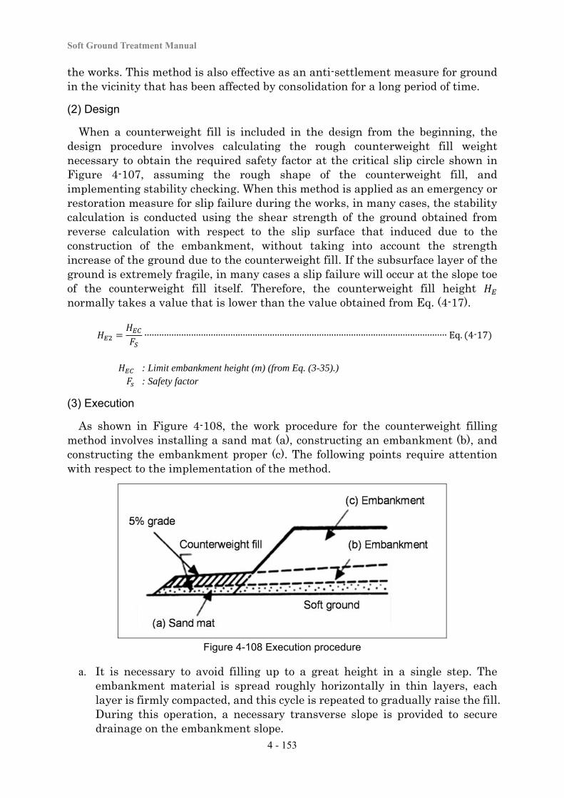
Soft Ground Treatment Manual
4 - 153
the works. This method is also effective as an anti-settlement measure for ground in the vicinity that has been affected by consolidation for a long period of time.
(2) Design
When a counterweight fill is included in the design from the beginning, the design procedure involves calculating the rough counterweight fill weight necessary to obtain the required safety factor at the critical slip circle shown in Figure 4-107, assuming the rough shape of the counterweight fill, and implementing stability checking. When this method is applied as an emergency or restoration measure for slip failure during the works, in many cases, the stability calculation is conducted using the shear strength of the ground obtained from reverse calculation with respect to the slip surface that induced due to the construction of the embankment, without taking into account the strength increase of the ground due to the counterweight fill. If the subsurface layer of the ground is extremely fragile, in many cases a slip failure will occur at the slope toe of the counterweight fill itself. Therefore, the counterweight fill height normally takes a value that is lower than the value obtained from Eq. (4-17).
∙∙∙∙∙∙∙∙∙∙∙∙∙∙∙∙∙∙∙∙∙∙∙∙∙∙∙∙∙∙∙∙∙∙∙∙∙∙∙∙∙∙∙∙∙∙∙∙∙∙∙∙∙∙∙∙∙∙∙∙∙∙∙∙∙∙∙∙∙∙∙∙∙∙∙∙∙∙∙∙∙∙∙∙∙∙∙∙∙∙∙∙∙∙∙∙∙∙∙∙∙∙∙∙∙∙∙∙∙∙∙∙∙∙∙∙∙∙∙∙∙∙∙ Eq. 4-17
: Limit embankment height (m) (from Eq. (3-35).) : Safety factor
(3) Execution
As shown in Figure 4-108, the work procedure for the counterweight filling method involves installing a sand mat (a), constructing an embankment (b), and constructing the embankment proper (c). The following points require attention with respect to the implementation of the method.
Figure 4-108 Execution procedure
a. It is necessary to avoid filling up to a great height in a single step. The embankment material is spread roughly horizontally in thin layers, each layer is firmly compacted, and this cycle is repeated to gradually raise the fill. During this operation, a necessary transverse slope is provided to secure drainage on the embankment slope.
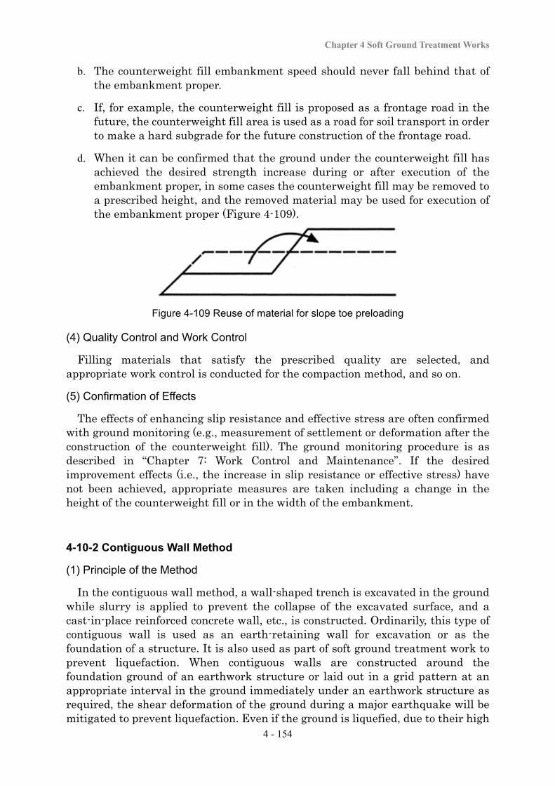
Chapter 4 Soft Ground Treatment Works
4 - 154
b. The counterweight fill embankment speed should never fall behind that of the embankment proper.
c. If, for example, the counterweight fill is proposed as a frontage road in the future, the counterweight fill area is used as a road for soil transport in order to make a hard subgrade for the future construction of the frontage road.
d. When it can be confirmed that the ground under the counterweight fill has achieved the desired strength increase during or after execution of the embankment proper, in some cases the counterweight fill may be removed to a prescribed height, and the removed material may be used for execution of the embankment proper (Figure 4-109).
Figure 4-109 Reuse of material for slope toe preloading
(4) Quality Control and Work Control
Filling materials that satisfy the prescribed quality are selected, and appropriate work control is conducted for the compaction method, and so on.
(5) Confirmation of Effects
The effects of enhancing slip resistance and effective stress are often confirmed with ground monitoring (e.g., measurement of settlement or deformation after the construction of the counterweight fill). The ground monitoring procedure is as described in “Chapter 7: Work Control and Maintenance”. If the desired improvement effects (i.e., the increase in slip resistance or effective stress) have not been achieved, appropriate measures are taken including a change in the height of the counterweight fill or in the width of the embankment.
4-10-2 Contiguous Wall Method
(1) Principle of the Method
In the contiguous wall method, a wall-shaped trench is excavated in the ground while slurry is applied to prevent the collapse of the excavated surface, and a cast-in-place reinforced concrete wall, etc., is constructed. Ordinarily, this type of contiguous wall is used as an earth-retaining wall for excavation or as the foundation of a structure. It is also used as part of soft ground treatment work to prevent liquefaction. When contiguous walls are constructed around the foundation ground of an earthwork structure or laid out in a grid pattern at an appropriate interval in the ground immediately under an earthwork structure as required, the shear deformation of the ground during a major earthquake will be mitigated to prevent liquefaction. Even if the ground is liquefied, due to their high
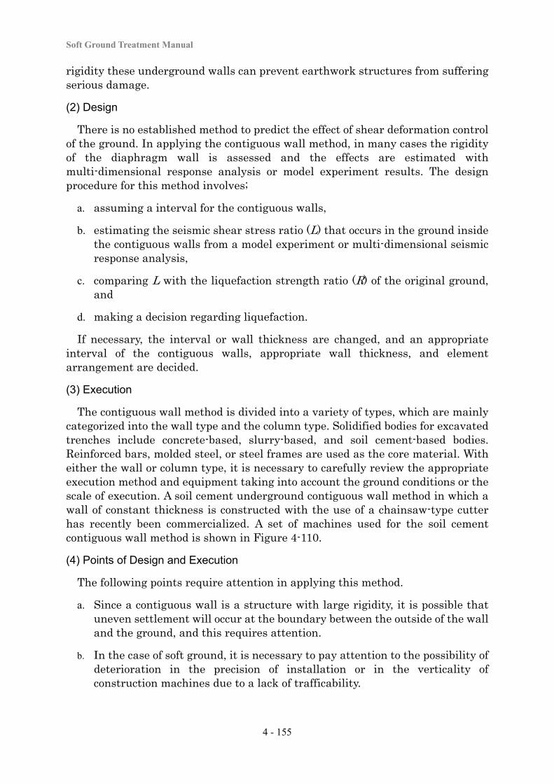
Soft Ground Treatment Manual
4 - 155
rigidity these underground walls can prevent earthwork structures from suffering serious damage.
(2) Design
There is no established method to predict the effect of shear deformation control of the ground. In applying the contiguous wall method, in many cases the rigidity of the diaphragm wall is assessed and the effects are estimated with multi-dimensional response analysis or model experiment results. The design procedure for this method involves;
a. assuming a interval for the contiguous walls,
b. estimating the seismic shear stress ratio (L) that occurs in the ground inside the contiguous walls from a model experiment or multi-dimensional seismic response analysis,
c. comparing L with the liquefaction strength ratio (R) of the original ground, and
d. making a decision regarding liquefaction.
If necessary, the interval or wall thickness are changed, and an appropriate interval of the contiguous walls, appropriate wall thickness, and element arrangement are decided.
(3) Execution
The contiguous wall method is divided into a variety of types, which are mainly categorized into the wall type and the column type. Solidified bodies for excavated trenches include concrete-based, slurry-based, and soil cement-based bodies. Reinforced bars, molded steel, or steel frames are used as the core material. With either the wall or column type, it is necessary to carefully review the appropriate execution method and equipment taking into account the ground conditions or the scale of execution. A soil cement underground contiguous wall method in which a wall of constant thickness is constructed with the use of a chainsaw-type cutter has recently been commercialized. A set of machines used for the soil cement contiguous wall method is shown in Figure 4-110.
(4) Points of Design and Execution
The following points require attention in applying this method.
a. Since a contiguous wall is a structure with large rigidity, it is possible that uneven settlement will occur at the boundary between the outside of the wall and the ground, and this requires attention.
b. In the case of soft ground, it is necessary to pay attention to the possibility of deterioration in the precision of installation or in the verticality of construction machines due to a lack of trafficability.
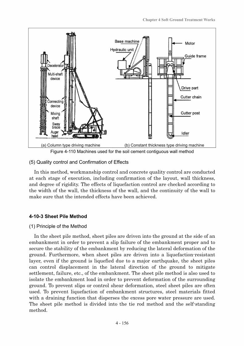
Chapter 4 Soft Ground Treatment Works
4 - 156
(a) Column type driving machine (b) Constant thickness type driving machine
Figure 4-110 Machines used for the soil cement contiguous wall method
(5) Quality control and Confirmation of Effects
In this method, workmanship control and concrete quality control are conducted at each stage of execution, including confirmation of the layout, wall thickness, and degree of rigidity. The effects of liquefaction control are checked according to the width of the wall, the thickness of the wall, and the continuity of the wall to make sure that the intended effects have been achieved.
4-10-3 Sheet Pile Method
(1) Principle of the Method
In the sheet pile method, sheet piles are driven into the ground at the side of an embankment in order to prevent a slip failure of the embankment proper and to secure the stability of the embankment by reducing the lateral deformation of the ground. Furthermore, when sheet piles are driven into a liquefaction-resistant layer, even if the ground is liquefied due to a major earthquake, the sheet piles can control displacement in the lateral direction of the ground to mitigate settlement, failure, etc., of the embankment. The sheet pile method is also used to isolate the embankment load in order to prevent deformation of the surrounding ground. To prevent slips or control shear deformation, steel sheet piles are often used. To prevent liquefaction of embankment structures, steel materials fitted with a draining function that disperses the excess pore water pressure are used. The sheet pile method is divided into the tie rod method and the self-standing method.
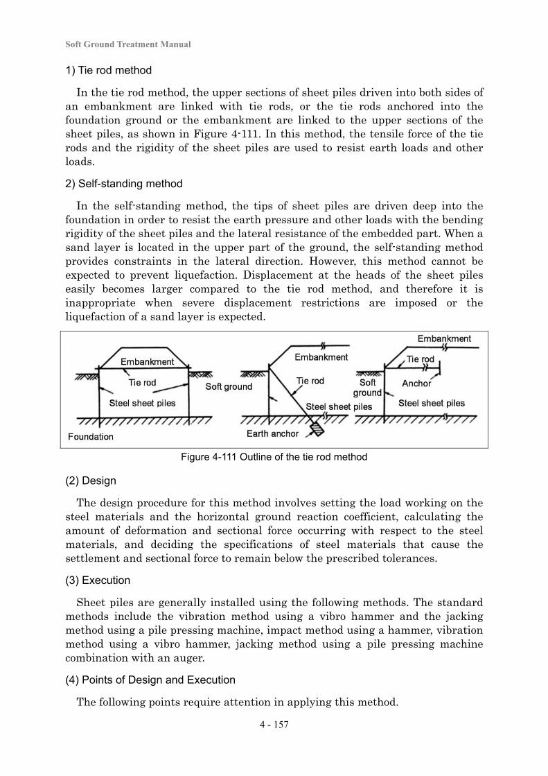
Soft Ground Treatment Manual
4 - 157
1) Tie rod method
In the tie rod method, the upper sections of sheet piles driven into both sides of an embankment are linked with tie rods, or the tie rods anchored into the foundation ground or the embankment are linked to the upper sections of the sheet piles, as shown in Figure 4-111. In this method, the tensile force of the tie rods and the rigidity of the sheet piles are used to resist earth loads and other loads.
2) Self-standing method
In the self-standing method, the tips of sheet piles are driven deep into the foundation in order to resist the earth pressure and other loads with the bending rigidity of the sheet piles and the lateral resistance of the embedded part. When a sand layer is located in the upper part of the ground, the self-standing method provides constraints in the lateral direction. However, this method cannot be expected to prevent liquefaction. Displacement at the heads of the sheet piles easily becomes larger compared to the tie rod method, and therefore it is inappropriate when severe displacement restrictions are imposed or the liquefaction of a sand layer is expected.
Figure 4-111 Outline of the tie rod method
(2) Design
The design procedure for this method involves setting the load working on the steel materials and the horizontal ground reaction coefficient, calculating the amount of deformation and sectional force occurring with respect to the steel materials, and deciding the specifications of steel materials that cause the settlement and sectional force to remain below the prescribed tolerances.
(3) Execution
Sheet piles are generally installed using the following methods. The standard methods include the vibration method using a vibro hammer and the jacking method using a pile pressing machine, impact method using a hammer, vibration method using a vibro hammer, jacking method using a pile pressing machine combination with an auger.
(4) Points of Design and Execution
The following points require attention in applying this method.
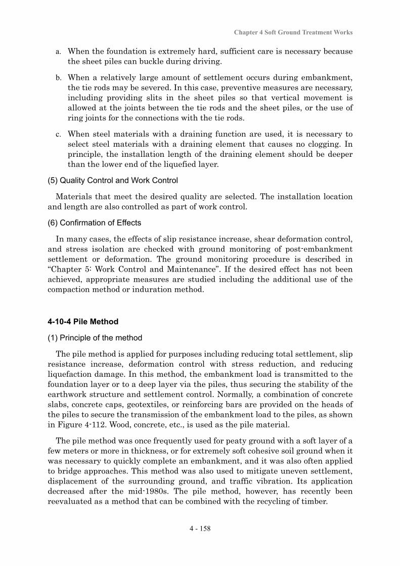
Chapter 4 Soft Ground Treatment Works
4 - 158
a. When the foundation is extremely hard, sufficient care is necessary because the sheet piles can buckle during driving.
b. When a relatively large amount of settlement occurs during embankment, the tie rods may be severed. In this case, preventive measures are necessary, including providing slits in the sheet piles so that vertical movement is allowed at the joints between the tie rods and the sheet piles, or the use of ring joints for the connections with the tie rods.
c. When steel materials with a draining function are used, it is necessary to select steel materials with a draining element that causes no clogging. In principle, the installation length of the draining element should be deeper than the lower end of the liquefied layer.
(5) Quality Control and Work Control
Materials that meet the desired quality are selected. The installation location and length are also controlled as part of work control.
(6) Confirmation of Effects
In many cases, the effects of slip resistance increase, shear deformation control, and stress isolation are checked with ground monitoring of post-embankment settlement or deformation. The ground monitoring procedure is described in “Chapter 5: Work Control and Maintenance”. If the desired effect has not been achieved, appropriate measures are studied including the additional use of the compaction method or induration method.
4-10-4 Pile Method
(1) Principle of the method
The pile method is applied for purposes including reducing total settlement, slip resistance increase, deformation control with stress reduction, and reducing liquefaction damage. In this method, the embankment load is transmitted to the foundation layer or to a deep layer via the piles, thus securing the stability of the earthwork structure and settlement control. Normally, a combination of concrete slabs, concrete caps, geotextiles, or reinforcing bars are provided on the heads of the piles to secure the transmission of the embankment load to the piles, as shown in Figure 4-112. Wood, concrete, etc., is used as the pile material.
The pile method was once frequently used for peaty ground with a soft layer of a few meters or more in thickness, or for extremely soft cohesive soil ground when it was necessary to quickly complete an embankment, and it was also often applied to bridge approaches. This method was also used to mitigate uneven settlement, displacement of the surrounding ground, and traffic vibration. Its application decreased after the mid-1980s. The pile method, however, has recently been reevaluated as a method that can be combined with the recycling of timber.
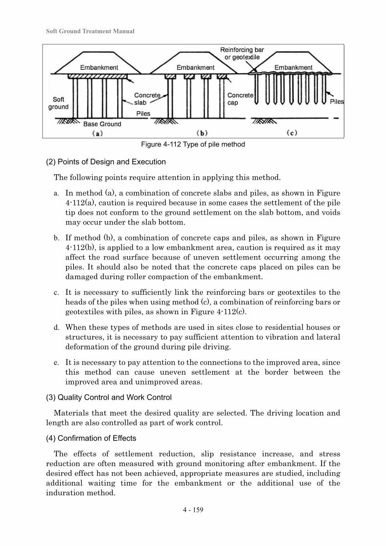
Soft Ground Treatment Manual
4 - 159
Figure 4-112 Type of pile method
(2) Points of Design and Execution
The following points require attention in applying this method.
a. In method (a), a combination of concrete slabs and piles, as shown in Figure 4-112(a), caution is required because in some cases the settlement of the pile tip does not conform to the ground settlement on the slab bottom, and voids may occur under the slab bottom.
b. If method (b), a combination of concrete caps and piles, as shown in Figure 4-112(b), is applied to a low embankment area, caution is required as it may affect the road surface because of uneven settlement occurring among the piles. It should also be noted that the concrete caps placed on piles can be damaged during roller compaction of the embankment.
c. It is necessary to sufficiently link the reinforcing bars or geotextiles to the heads of the piles when using method (c), a combination of reinforcing bars or geotextiles with piles, as shown in Figure 4-112(c).
d. When these types of methods are used in sites close to residential houses or structures, it is necessary to pay sufficient attention to vibration and lateral deformation of the ground during pile driving.
e. It is necessary to pay attention to the connections to the improved area, since this method can cause uneven settlement at the border between the improved area and unimproved areas.
(3) Quality Control and Work Control
Materials that meet the desired quality are selected. The driving location and length are also controlled as part of work control.
(4) Confirmation of Effects
The effects of settlement reduction, slip resistance increase, and stress reduction are often measured with ground monitoring after embankment. If the desired effect has not been achieved, appropriate measures are studied, including additional waiting time for the embankment or the additional use of the induration method.
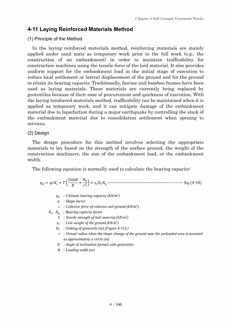
Chapter 4 Soft Ground Treatment Works
4 - 160
4-11 Laying Reinforced Materials Method
(1) Principle of the Method
In the laying reinforced materials method, reinforcing materials are mainly applied under sand mats as temporary work prior to the full work (e.g., the construction of an embankment) in order to maintain trafficability for construction machines using the tensile force of the laid material. It also provides uniform support for the embankment load in the initial stage of execution to reduce local settlement or lateral displacement of the ground and for the ground to retain its bearing capacity. Traditionally, fascine and bamboo frames have been used as laying materials. These materials are currently being replaced by geotextiles because of their ease of procurement and quickness of execution. With the laying reinforced materials method, trafficability can be maintained when it is applied as temporary work, and it can mitigate damage of the embankment material due to liquefaction during a major earthquake by controlling the slack of the embankment material due to consolidation settlement when opening to services.
(2) Design
The design procedure for this method involves selecting the appropriate materials to lay based on the strength of the surface ground, the weight of the construction machinery, the size of the embankment load, or the embankment width.
The following equation is normally used to calculate the bearing capacity:
2sin∙∙∙∙∙∙∙∙∙∙∙∙∙∙∙∙∙∙∙∙∙∙∙∙∙∙∙∙∙∙∙∙∙∙∙∙∙∙∙∙∙∙∙∙∙∙∙∙∙∙∙∙∙∙∙∙∙∙∙∙∙∙∙∙∙∙∙∙∙∙∙∙∙∙∙ Eq. 4-18
: Ultimate bearing capacity (kN/m2)
: Shape factor
c : Cohesive force of cohesive soil ground (kN/m2)
, : Bearing capacity factor
T : Tensile strength of laid material (kN/m2)
: Unit weight of the ground (kN/m3)
: Sinking of geotextile (m) (Figure 4-113.)
r : Virtual radius when the shape change of the ground near the preloaded area is assumed
as approximately a circle (m)
: Angle of inclination formed with geotextiles
B : Loading width (m)
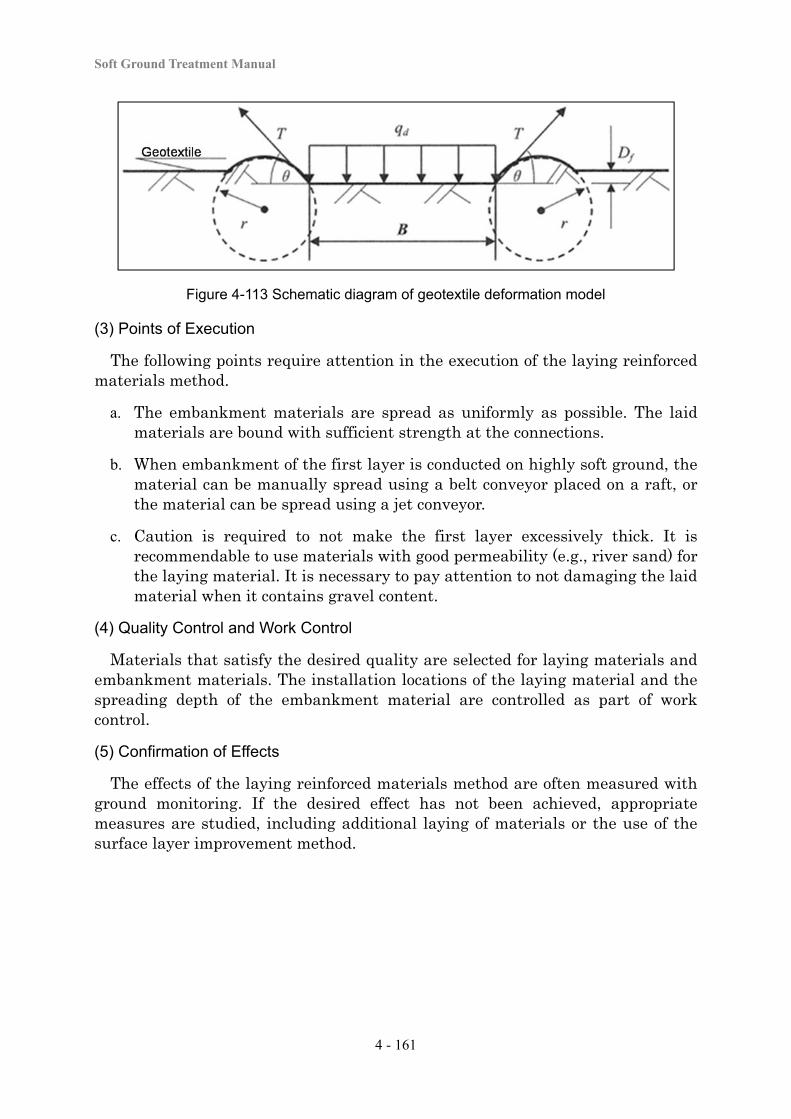
Soft Ground Treatment Manual
4 - 161
Figure 4-113 Schematic diagram of geotextile deformation model
(3) Points of Execution
The following points require attention in the execution of the laying reinforced materials method.
a. The embankment materials are spread as uniformly as possible. The laid materials are bound with sufficient strength at the connections.
b. When embankment of the first layer is conducted on highly soft ground, the material can be manually spread using a belt conveyor placed on a raft, or the material can be spread using a jet conveyor.
c. Caution is required to not make the first layer excessively thick. It is recommendable to use materials with good permeability (e.g., river sand) for the laying material. It is necessary to pay attention to not damaging the laid material when it contains gravel content.
(4) Quality Control and Work Control
Materials that satisfy the desired quality are selected for laying materials and embankment materials. The installation locations of the laying material and the spreading depth of the embankment material are controlled as part of work control.
(5) Confirmation of Effects
The effects of the laying reinforced materials method are often measured with ground monitoring. If the desired effect has not been achieved, appropriate measures are studied, including additional laying of materials or the use of the surface layer improvement method.

Chapter 5
Work Control and Maintenance
Soft Ground Treatment Manual
5 - 1
5-1 Work Control
5-1-1 Concepts
To conduct the earthwork or the treatment work on soft ground, the following are necessary for proper construction works;
a. sufficiently understanding the theory of the selected methods, the contents of the design of the selected methods, matters that require attention, and the local conditions
b. constantly checking the progress of work, the actions of the ground, and the quality, shape and dimensions of the earthwork structure and the improvement work
c. appropriate conduct the work
Also the following actions are necessary to avoid construction problem; - to check if the work is progressing on schedule - to check if the required quality or shape is being provided during the work - to investigate problems quickly and find causes - to carry out correction or improvement whenever any nonconformity in terms
of the required shape and dimensions is found
This kind of operation is generally referred to as work control. The purpose of work control is to complete an earthwork structure of the required quality, shape, and dimensions within the predetermined work period and in an economical way. Work control also includes;
- machinery control, in which the operational conditions of construction machines are checked,
- safety control, in which the safety of work is ensured, and - environmental control, in which the environment is protected so as to ensure
smooth and safe execution of work.
When an earthwork structure is constructed on soft ground, work control should be conducted covering process, quality, and shape, as well as concerning ground stability, settlement management, and deformation consolidation of the surrounding ground or structures. The construction and work control flows for the construction of earthwork structures on soft ground and soft ground treatment work are shown in Figure 5-1 as an example. It is necessary to be prepared for abnormal situations that were unforeseen in the design stage when planning and executing the construction of an earthwork structure on soft ground or soft ground treatment work. Even if the design and the work was conducted precisely, the quality of the works could not be kept, or the ground sometimes could fail, because there are some uncertainties inherent in investigations, design and works. Once the foundation ground has failed, it would take a large amount of costs and a long period to solve the situation. To prevent this problem, the followings are important;
- to develop a construction plan and work control plan that protect against uncertainties,
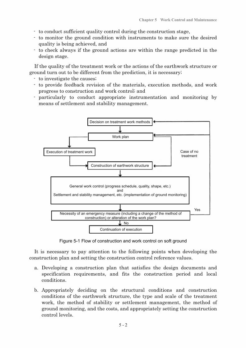
Chapter 5 Work Control and Maintenance
5 - 2
- to conduct sufficient quality control during the construction stage, - to monitor the ground condition with instruments to make sure the desired
quality is being achieved, and - to check always if the ground actions are within the range predicted in the
design stage.
If the quality of the treatment work or the actions of the earthwork structure or ground turn out to be different from the prediction, it is necessary;
- to investigate the causes; - to provide feedback revision of the materials, execution methods, and work
progress to construction and work control; and - particularly to conduct appropriate instrumentation and monitoring by
means of settlement and stability management.
Figure 5-1 Flow of construction and work control on soft ground
It is necessary to pay attention to the following points when developing the construction plan and setting the construction control reference values.
a. Developing a construction plan that satisfies the design documents and specification requirements, and fits the construction period and local conditions.
b. Appropriately deciding on the structural conditions and construction conditions of the earthwork structure, the type and scale of the treatment work, the method of stability or settlement management, the method of ground monitoring, and the costs, and appropriately setting the construction control levels.
No
Decision on treatment work methods
Work plan
Execution of treatment work Case of no treatment
Construction of earthwork structure
General work control (progress schedule, quality, shape, etc.) and
Settlement and stability management, etc. (implementation of ground monitoring)
Necessity of an emergency measure (including a change of the method of construction) or alteration of the work plan?
Yes
Continuation of execution
Soft Ground Treatment Manual
5 - 3
c. Planning ground monitoring necessary to manage settlement, stability, and deformation. If an anomaly is confirmed by the ground monitoring, quickly investigating the cause, taking necessary corrective actions, and making necessary corrections to the original design or construction plan.
d. When work is conducted on soft ground, it can change the groundwater environment and ground environment, vibration or noise generated from the work can affect the surrounding environment, and there can be unexpected impacts on facilities in the vicinity. It is therefore necessary to take advance actions depending on the surrounding environmental conditions and their importance.
5-1-2 Work Control
The following points require attention when soft ground treatment is performed or earthwork structures are constructed by considering the characteristics of the soft ground, including the need for of a long period of time for consolidation settlement.
a. When soft ground treatment work is conducted, completing the treatment work at an early a stage to stabilize the ground before starting construction of an earthwork structure such as an embankment.
b. Conducting stability management against failure attributable to a lack of bearing capacity or shear resistance of the foundation ground, or conducting settlement management of the earthwork structure during construction of the earthwork structure, and changing the execution method or adjust the filling rate based on the results.
c. After completion of embankment, allowing a sufficient waiting time until the start of paving or the construction of a structure in order to reduce the amount of settlement that could continue during road service period.
In addition, it is necessary to conduct daily ground monitoring while paying attention to the following points, and to proceed with work while always ascertaining the local behavior.
a. Thoroughly checking the required conditions including the drawings and specifications against the local conditions and developing a construction plan that can ensure the process, quality, and shape.
b. Conducting work carefully and meticulously according to the construction plan. Particularly, caution is required if any other structures are close to the work site. Sufficient safety measures are taken to prevent machine-related accidents such as construction machines falling or toppling.
c. When work is conducted on soft ground, whichever method is used, it is essential to ensure trafficability for construction machines, and so in many cases the sand mat method or surface mixing method are used together (“4-3-1 Surface Water Drainage Method”, “4-3-2 Sand Mat Method” and
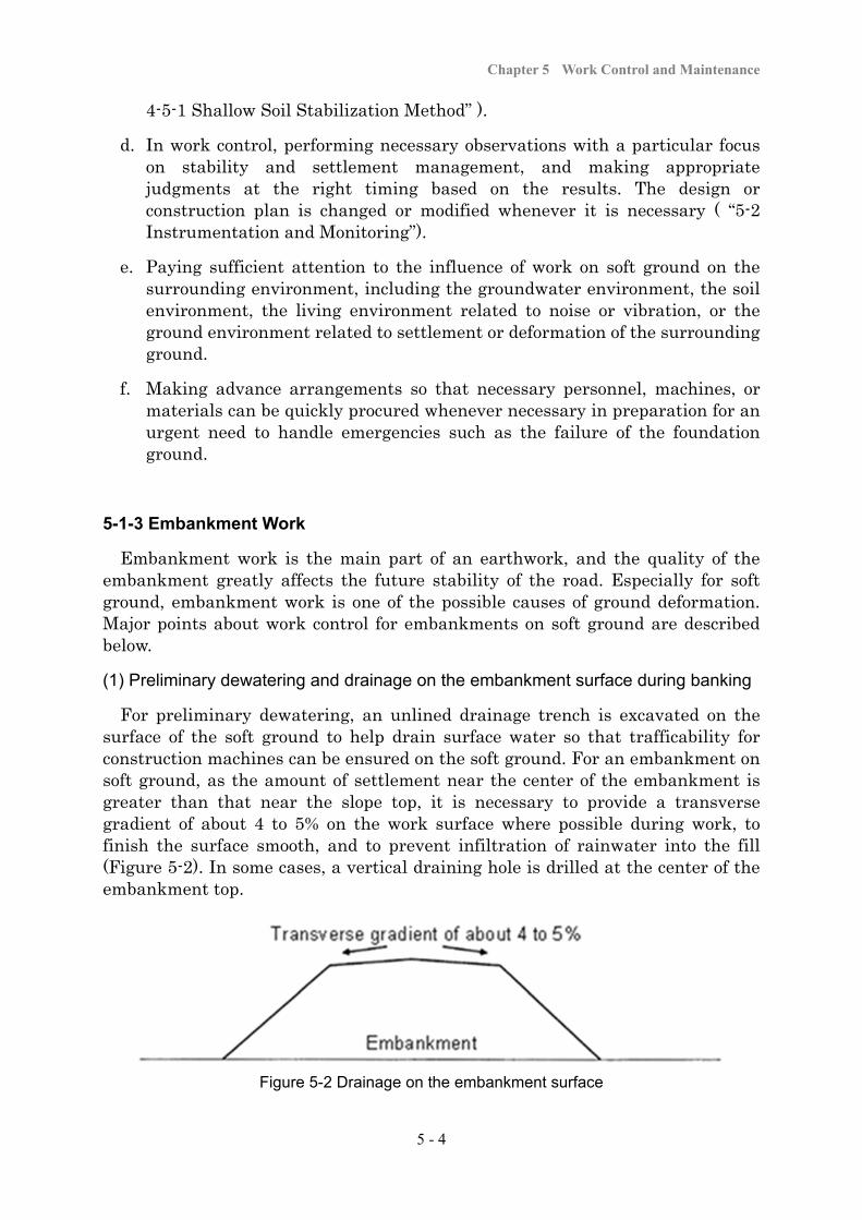
Chapter 5 Work Control and Maintenance
5 - 4
4-5-1 Shallow Soil Stabilization Method” ).
d. In work control, performing necessary observations with a particular focus on stability and settlement management, and making appropriate judgments at the right timing based on the results. The design or construction plan is changed or modified whenever it is necessary ( “5-2 Instrumentation and Monitoring”).
e. Paying sufficient attention to the influence of work on soft ground on the surrounding environment, including the groundwater environment, the soil environment, the living environment related to noise or vibration, or the ground environment related to settlement or deformation of the surrounding ground.
f. Making advance arrangements so that necessary personnel, machines, or materials can be quickly procured whenever necessary in preparation for an urgent need to handle emergencies such as the failure of the foundation ground.
5-1-3 Embankment Work
Embankment work is the main part of an earthwork, and the quality of the embankment greatly affects the future stability of the road. Especially for soft ground, embankment work is one of the possible causes of ground deformation. Major points about work control for embankments on soft ground are described below.
(1) Preliminary dewatering and drainage on the embankment surface during banking
For preliminary dewatering, an unlined drainage trench is excavated on the surface of the soft ground to help drain surface water so that trafficability for construction machines can be ensured on the soft ground. For an embankment on soft ground, as the amount of settlement near the center of the embankment is greater than that near the slope top, it is necessary to provide a transverse gradient of about 4 to 5% on the work surface where possible during work, to finish the surface smooth, and to prevent infiltration of rainwater into the fill (Figure 5-2). In some cases, a vertical draining hole is drilled at the center of the embankment top.
Figure 5-2 Drainage on the embankment surface
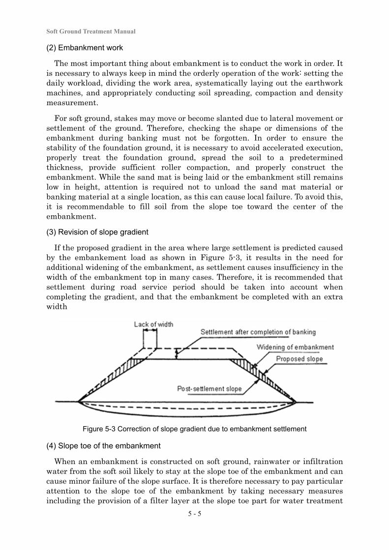
Soft Ground Treatment Manual
5 - 5
(2) Embankment work
The most important thing about embankment is to conduct the work in order. It is necessary to always keep in mind the orderly operation of the work: setting the daily workload, dividing the work area, systematically laying out the earthwork machines, and appropriately conducting soil spreading, compaction and density measurement.
For soft ground, stakes may move or become slanted due to lateral movement or settlement of the ground. Therefore, checking the shape or dimensions of the embankment during banking must not be forgotten. In order to ensure the stability of the foundation ground, it is necessary to avoid accelerated execution, properly treat the foundation ground, spread the soil to a predetermined thickness, provide sufficient roller compaction, and properly construct the embankment. While the sand mat is being laid or the embankment still remains low in height, attention is required not to unload the sand mat material or banking material at a single location, as this can cause local failure. To avoid this, it is recommendable to fill soil from the slope toe toward the center of the embankment.
(3) Revision of slope gradient
If the proposed gradient in the area where large settlement is predicted caused by the embankement load as shown in Figure 5-3, it results in the need for additional widening of the embankment, as settlement causes insufficiency in the width of the embankment top in many cases. Therefore, it is recommended that settlement during road service period should be taken into account when completing the gradient, and that the embankment be completed with an extra width
Figure 5-3 Correction of slope gradient due to embankment settlement
(4) Slope toe of the embankment
When an embankment is constructed on soft ground, rainwater or infiltration water from the soft soil likely to stay at the slope toe of the embankment and can cause minor failure of the slope surface. It is therefore necessary to pay particular attention to the slope toe of the embankment by taking necessary measures including the provision of a filter layer at the slope toe part for water treatment
Chapter 5 Work Control and Maintenance
5 - 6
(Figure 4-49).
5-1-4 Quality Control and Work Progress Control
In soft ground treatment work, the effects of securing trafficability, restraining settlement, securing stability, etc., are shown if construction is carried out following the goal studied in the design. Therefore, it is important to conduct quality control and progress control according to the basic principles and execution of each method in order to make sure that the treatment work has been conducted to follow its original goal. Quality control involves implementing required examinations during execution, inspecting the quality of the work for whether it conforms to the requirements, and, if the work was done improperly, examining the cause and implementing corrective measures to ensure the required quality is obtained. Work progress control involves investigating whether the treatment work matches the required shape and dimensions, and, if the work was done without satisfying the control reference values, examining the cause and implementing corrective measures to ensure the required shape and size are obtained. For the control items of the work for each separate measure, refer to Chapter 4.

Soft Ground Treatment Manual
5 - 7
5-2 Instrumentation and Monitoring
When an embankment is constructed on soft ground, settlement and instability of the foundation ground caused by the embankment load can become a problem, but in many cases the actual actions do not agree with the actions predicted in the design. Therefore, even if the works are carried out according to the proper design, unexpected deformation and failure of the foundation ground could occur. This is because there are many uncertainties inherently present in investigation, design, and construction, even if measures are taken that are considered to be sufficient at the present time. Instrumentation and monitoring on soft ground is meant to provide additional information obtained in the construction process to compensate for uncertain factors and to reliably complete the embankment work. Specifically, appropriate measurement devices are arranged, ground monitoring is conducted for settlement management or stability management, the obtained measurement information is evaluated, and this is fed back to the next work process. Depending on the circumstances, in some cases a review is carried out from the design stage. The operational flow of instrumentation and monitoring is shown in Figure 5-4. However, if instrumentation and monitoring is not necessary for small-scale work, etc., this does not apply.
Figure 5-4 Work control with soft ground monitoring
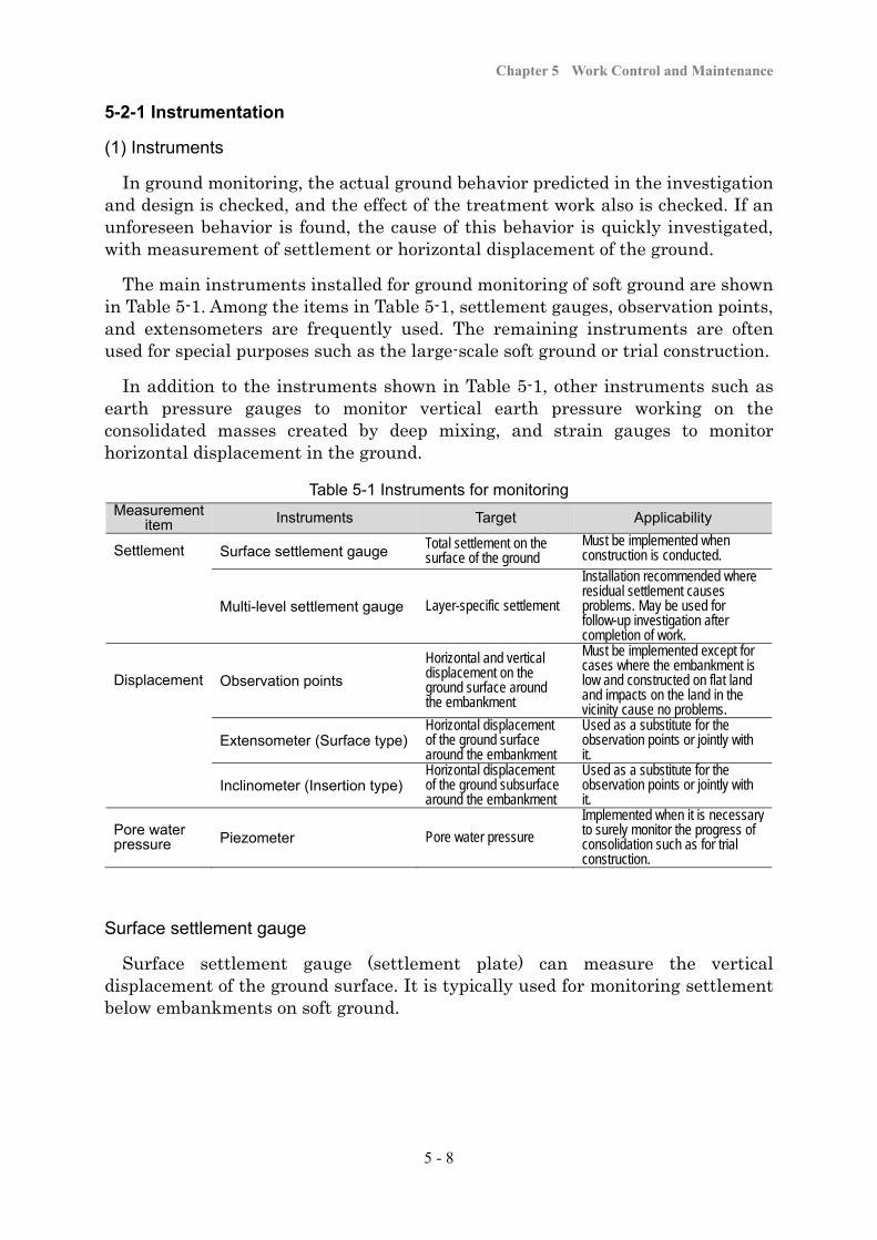
Chapter 5 Work Control and Maintenance
5 - 8
5-2-1 Instrumentation
(1) Instruments
In ground monitoring, the actual ground behavior predicted in the investigation and design is checked, and the effect of the treatment work also is checked. If an unforeseen behavior is found, the cause of this behavior is quickly investigated, with measurement of settlement or horizontal displacement of the ground.
The main instruments installed for ground monitoring of soft ground are shown in Table 5-1. Among the items in Table 5-1, settlement gauges, observation points, and extensometers are frequently used. The remaining instruments are often used for special purposes such as the large-scale soft ground or trial construction.
In addition to the instruments shown in Table 5-1, other instruments such as earth pressure gauges to monitor vertical earth pressure working on the consolidated masses created by deep mixing, and strain gauges to monitor horizontal displacement in the ground.
Table 5-1 Instruments for monitoring Measurement
item Instruments Target Applicability
Settlement Surface settlement gauge Total settlement on the surface of the ground
Must be implemented when construction is conducted.
Multi-level settlement gauge Layer-specific settlement
Installation recommended where residual settlement causes problems. May be used for follow-up investigation after completion of work.
Displacement Observation points
Horizontal and vertical displacement on the ground surface around the embankment
Must be implemented except for cases where the embankment is low and constructed on flat land and impacts on the land in the vicinity cause no problems.
Extensometer (Surface type)Horizontal displacement of the ground surface around the embankment
Used as a substitute for the observation points or jointly with it.
Inclinometer (Insertion type) Horizontal displacement of the ground subsurface around the embankment
Used as a substitute for the observation points or jointly with it.
Pore water pressure Piezometer Pore water pressure
Implemented when it is necessary to surely monitor the progress of consolidation such as for trial construction.
Surface settlement gauge
Surface settlement gauge (settlement plate) can measure the vertical displacement of the ground surface. It is typically used for monitoring settlement below embankments on soft ground.
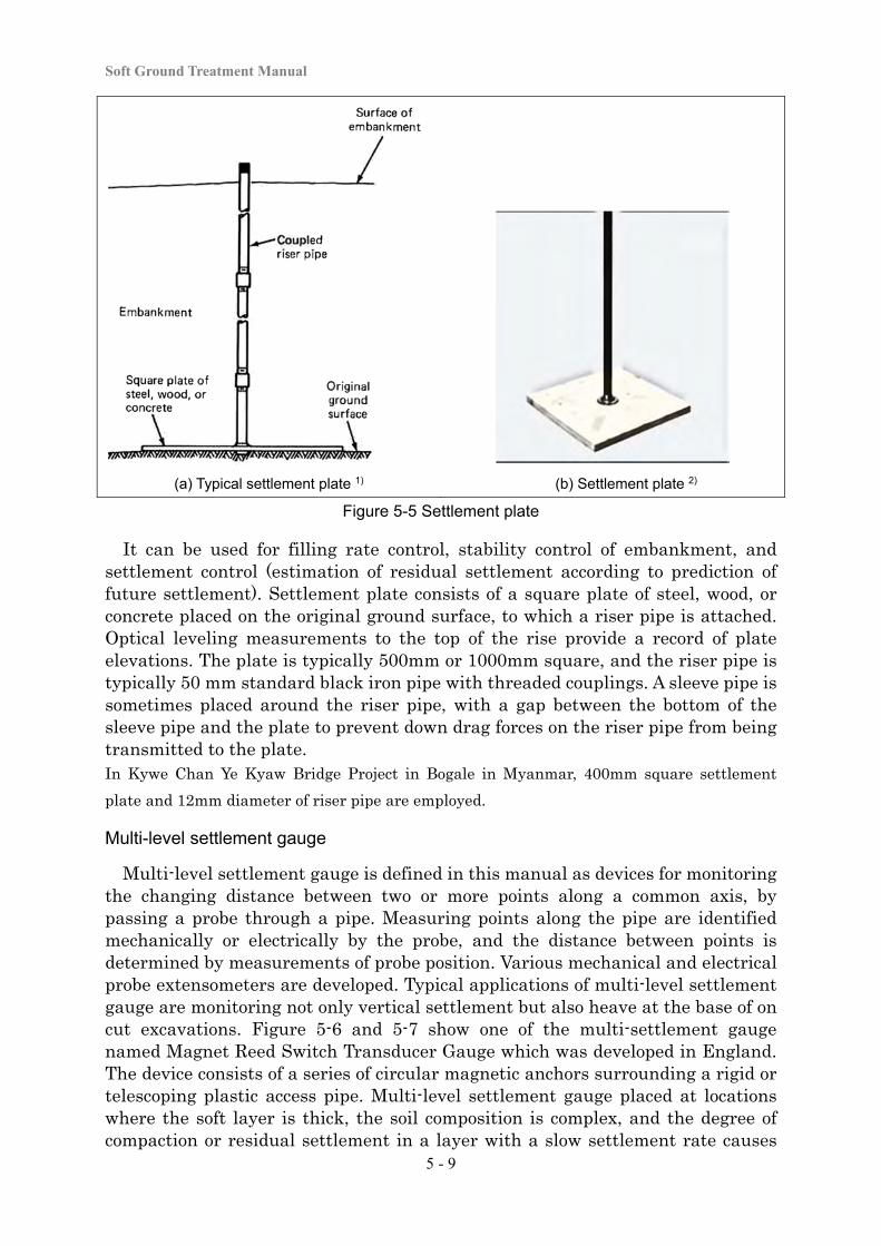
Soft Ground Treatment Manual
5 - 9
(a) Typical settlement plate 1) (b) Settlement plate 2)
Figure 5-5 Settlement plate
It can be used for filling rate control, stability control of embankment, and settlement control (estimation of residual settlement according to prediction of future settlement). Settlement plate consists of a square plate of steel, wood, or concrete placed on the original ground surface, to which a riser pipe is attached. Optical leveling measurements to the top of the rise provide a record of plate elevations. The plate is typically 500mm or 1000mm square, and the riser pipe is typically 50 mm standard black iron pipe with threaded couplings. A sleeve pipe is sometimes placed around the riser pipe, with a gap between the bottom of the sleeve pipe and the plate to prevent down drag forces on the riser pipe from being transmitted to the plate. In Kywe Chan Ye Kyaw Bridge Project in Bogale in Myanmar, 400mm square settlement
plate and 12mm diameter of riser pipe are employed.
Multi-level settlement gauge
Multi-level settlement gauge is defined in this manual as devices for monitoring the changing distance between two or more points along a common axis, by passing a probe through a pipe. Measuring points along the pipe are identified mechanically or electrically by the probe, and the distance between points is determined by measurements of probe position. Various mechanical and electrical probe extensometers are developed. Typical applications of multi-level settlement gauge are monitoring not only vertical settlement but also heave at the base of on cut excavations. Figure 5-6 and 5-7 show one of the multi-settlement gauge named Magnet Reed Switch Transducer Gauge which was developed in England. The device consists of a series of circular magnetic anchors surrounding a rigid or telescoping plastic access pipe. Multi-level settlement gauge placed at locations where the soft layer is thick, the soil composition is complex, and the degree of compaction or residual settlement in a layer with a slow settlement rate causes
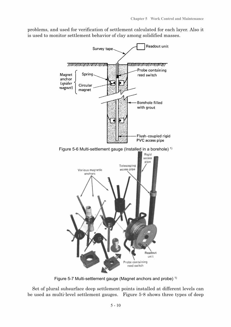
Chapter 5 Work Control and Maintenance
5 - 10
problems, and used for verification of settlement calculated for each layer. Also it is used to monitor settlement behavior of clay among solidified masses.
Figure 5-6 Multi-settlement gauge (Installed in a borehole) 1)
Figure 5-7 Multi-settlement gauge (Magnet anchors and probe) 1)
Set of plural subsurface deep settlement points installed at different levels can be used as multi-level settlement gauges. Figure 5-8 shows three types of deep
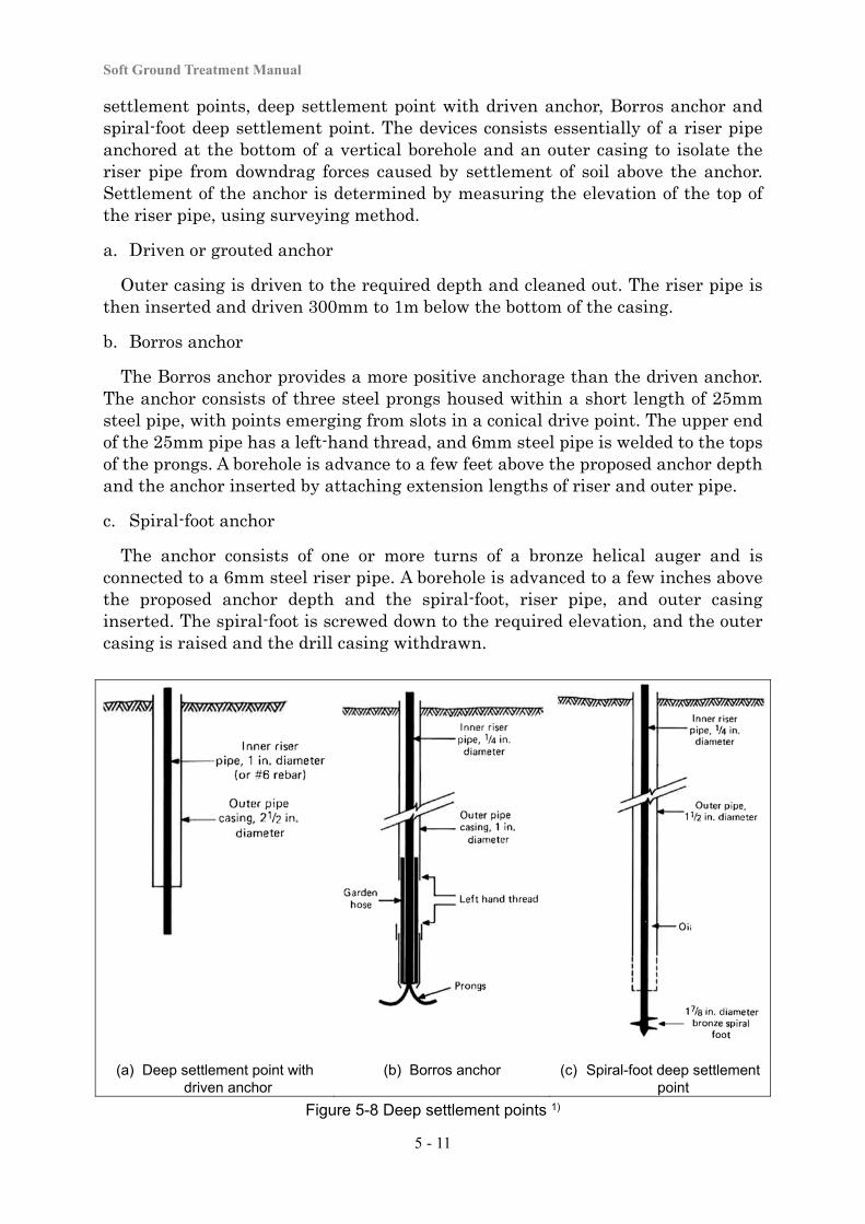
Soft Ground Treatment Manual
5 - 11
settlement points, deep settlement point with driven anchor, Borros anchor and spiral-foot deep settlement point. The devices consists essentially of a riser pipe anchored at the bottom of a vertical borehole and an outer casing to isolate the riser pipe from downdrag forces caused by settlement of soil above the anchor. Settlement of the anchor is determined by measuring the elevation of the top of the riser pipe, using surveying method.
a. Driven or grouted anchor
Outer casing is driven to the required depth and cleaned out. The riser pipe is then inserted and driven 300mm to 1m below the bottom of the casing.
b. Borros anchor
The Borros anchor provides a more positive anchorage than the driven anchor. The anchor consists of three steel prongs housed within a short length of 25mm steel pipe, with points emerging from slots in a conical drive point. The upper end of the 25mm pipe has a left-hand thread, and 6mm steel pipe is welded to the tops of the prongs. A borehole is advance to a few feet above the proposed anchor depth and the anchor inserted by attaching extension lengths of riser and outer pipe.
c. Spiral-foot anchor
The anchor consists of one or more turns of a bronze helical auger and is connected to a 6mm steel riser pipe. A borehole is advanced to a few inches above the proposed anchor depth and the spiral-foot, riser pipe, and outer casing inserted. The spiral-foot is screwed down to the required elevation, and the outer casing is raised and the drill casing withdrawn.
(a) Deep settlement point with driven anchor
(b) Borros anchor (c) Spiral-foot deep settlement point
Figure 5-8 Deep settlement points 1)

Chapter 5 Work Control and Maintenance
5 - 12
Observation point on surface of ground
Observation point is used to monitor anomalies of the ground around the embankment for stability management. A typical measuring point for monitoring settlement of the ground surface is shown in Figure 5-9(a). Figure 5-9(b) shows a typical measuring point for monitoring settlement on the surfaces of embankment dams. Also simple stakes as shown in Figure 5-9(c) are used in highway and other work for monitoring offsets from a baseline.
(a) Typical observation point 1) (b) Observation point for embankment dams 1)
(c) Reference stakes 3)
Figure 5-9 Observation points
A stable reference datum is required for all survey measurements of absolute deformation. A reference datum for measurements of vertical deformation is referred to a benchmark. Figure 5-10 shows an arrangement for a benchmark installation in firm base layer, with a grouted anchor and the inner rod centered in the casing with nylon spacers. The space between the rod and casing may be filled with heavy oil or bentonite slurry to minimize friction.
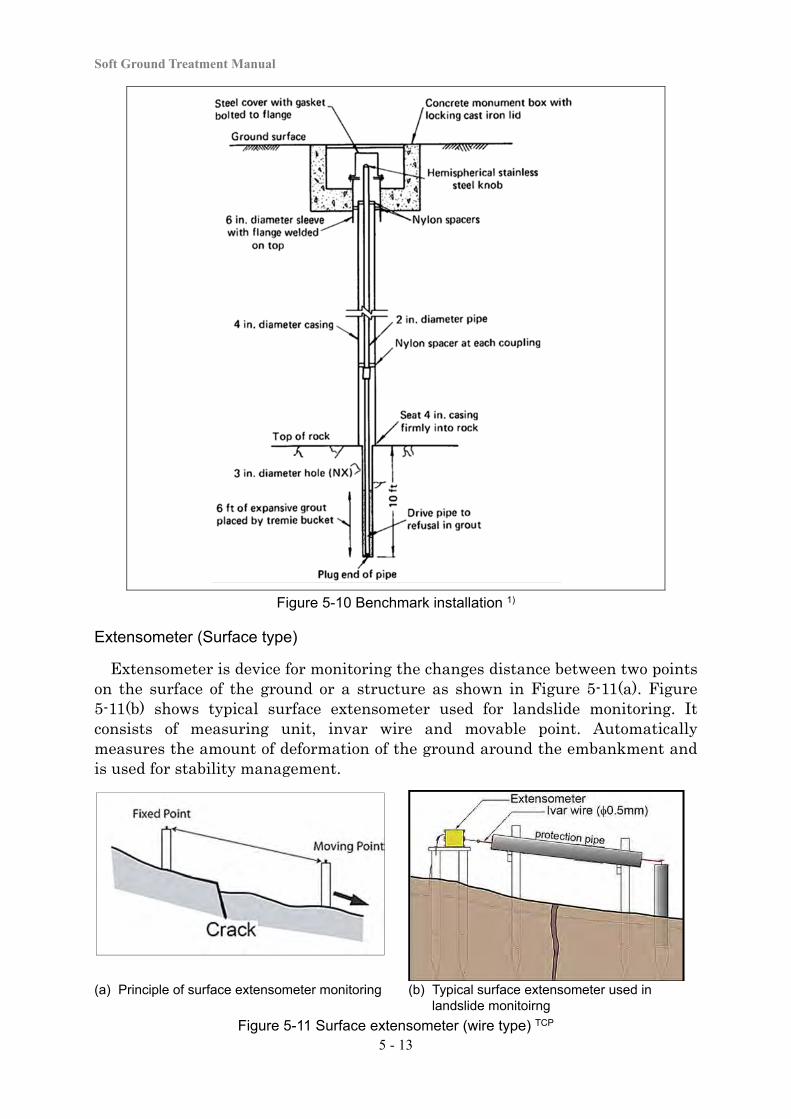
Soft Ground Treatment Manual
5 - 13
Figure 5-10 Benchmark installation 1)
Extensometer (Surface type)
Extensometer is device for monitoring the changes distance between two points on the surface of the ground or a structure as shown in Figure 5-11(a). Figure 5-11(b) shows typical surface extensometer used for landslide monitoring. It consists of measuring unit, invar wire and movable point. Automatically measures the amount of deformation of the ground around the embankment and is used for stability management.
(a) Principle of surface extensometer monitoring (b) Typical surface extensometer used in landslide monitoirng
Figure 5-11 Surface extensometer (wire type) TCP
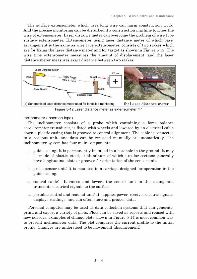
Chapter 5 Work Control and Maintenance
5 - 14
The surface extensometer which uses long wire can harm construction work. And the precise monitoring can be disturbed if a construction machine touches the wire of extensometer. Laser distance meter can overcome the problem of wire type surface extensometer. Extensometer using laser distance meter of which basic arrangement is the same as wire type extensometer, consists of two stakes which are for fixing the laser distance meter and for target as shown in Figure 5-12. The wire type extensometer measures the amount of displacement, and the laser distance meter measures exact distance between two stakes.
(a) Schematic of laser distance meter used for landslide monitoring (b) Laser distance meter
Figure 5-12 Laser distance meter as extensometer TCP
Inclinometer (Insertion type) The inclinometer consists of a probe which containing a force balance
accelerometer transducer, is fitted with wheels and lowered by an electrical cable down a plastic casing that is grooved to control alignment. The cable is connected to a readout unit, and data can be recorded manually or automatically. The inclinometer system has four main components:
a. guide casing: It is permanently installed in a borehole in the ground. It may be made of plastic, steel, or aluminum of which circular sections generally have longitudinal slots or grooves for orientation of the sensor unit.
b. probe sensor unit: It is mounted in a carriage designed for operation in the guide casing.
c. control cable: It raises and lowers the sensor unit in the casing and transmits electrical signals to the surface.
d. portable control and readout unit: It supplies power, receives electric signals, displays readings, and can often store and process data.
Personal computer may be used as data collection systems that can generate, print, and export a variety of plots. Plots can be saved as reports and reused with new surveys. examples of change plots shown in Figure 5-14 is most common way to present inclinometer data. The plot compares the current profile to the initial profile. Changes are understood to be movement (displacement).
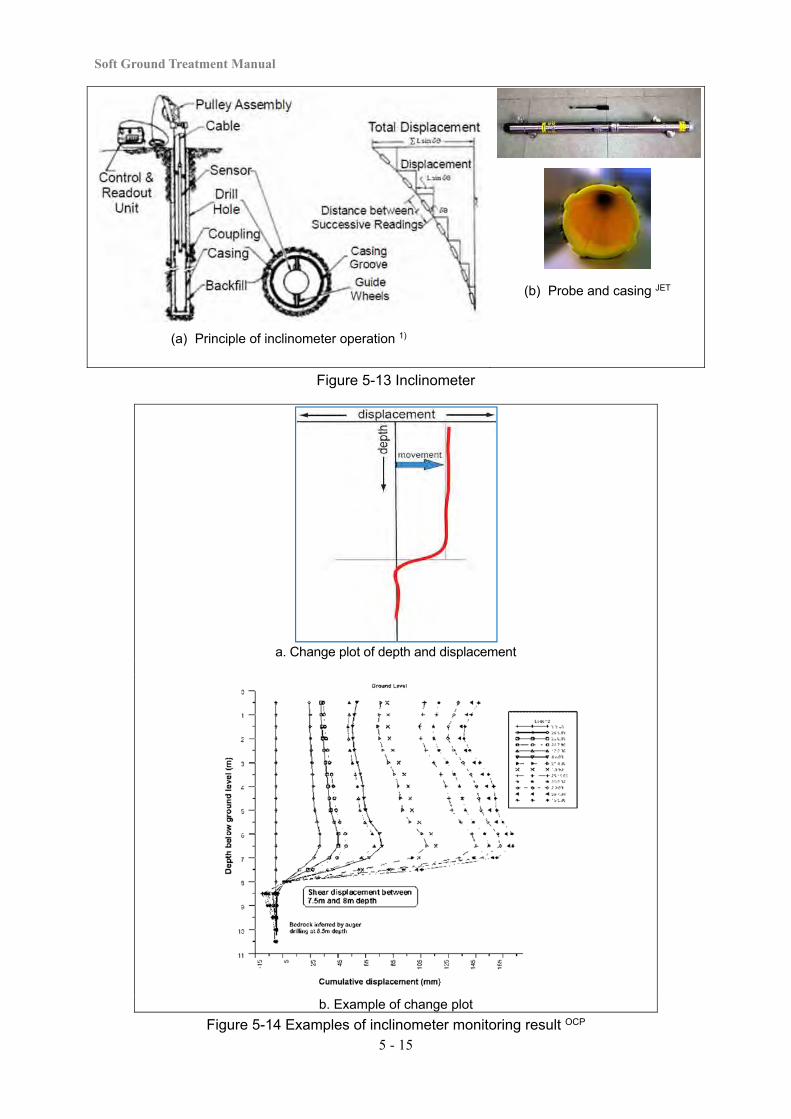
Soft Ground Treatment Manual
5 - 15
(a) Principle of inclinometer operation 1)
(b) Probe and casing JET
Figure 5-13 Inclinometer
a. Change plot of depth and displacement
b. Example of change plot
Figure 5-14 Examples of inclinometer monitoring result OCP
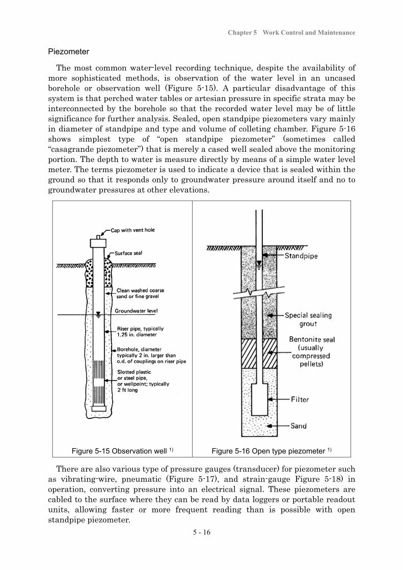
Chapter 5 Work Control and Maintenance
5 - 16
Piezometer
The most common water-level recording technique, despite the availability of more sophisticated methods, is observation of the water level in an uncased borehole or observation well (Figure 5-15). A particular disadvantage of this system is that perched water tables or artesian pressure in specific strata may be interconnected by the borehole so that the recorded water level may be of little significance for further analysis. Sealed, open standpipe piezometers vary mainly in diameter of standpipe and type and volume of colleting chamber. Figure 5-16 shows simplest type of “open standpipe piezometer” (sometimes called “casagrande piezometer”) that is merely a cased well sealed above the monitoring portion. The depth to water is measure directly by means of a simple water level meter. The terms piezometer is used to indicate a device that is sealed within the ground so that it responds only to groundwater pressure around itself and no to groundwater pressures at other elevations.
Figure 5-15 Observation well 1) Figure 5-16 Open type piezometer 1)
There are also various type of pressure gauges (transducer) for piezometer such as vibrating-wire, pneumatic (Figure 5-17), and strain-gauge Figure 5-18) in operation, converting pressure into an electrical signal. These piezometers are cabled to the surface where they can be read by data loggers or portable readout units, allowing faster or more frequent reading than is possible with open standpipe piezometer.
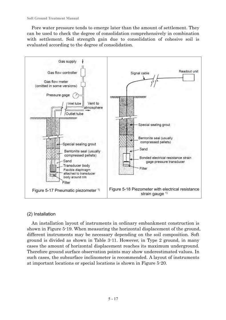
Soft Ground Treatment Manual
5 - 17
Pore water pressure tends to emerge later than the amount of settlement. They can be used to check the degree of consolidation comprehensively in combination with settlement. Soil strength gain due to consolidation of cohesive soil is evaluated according to the degree of consolidation.
Figure 5-17 Pneumatic piezometer 1) Figure 5-18 Piezometer with electrical resistance strain gauge 1)
(2) Installation
An installation layout of instruments in ordinary embankment construction is shown in Figure 5-19. When measuring the horizontal displacement of the ground, different instruments may be necessary depending on the soil composition. Soft ground is divided as shown in Table 3-11. However, in Type 2 ground, in many cases the amount of horizontal displacement reaches its maximum underground. Therefore ground surface observation points may show underestimated values. In such cases, the subsurface inclinometer is recommended. A layout of instruments at important locations or special locations is shown in Figure 5-20.
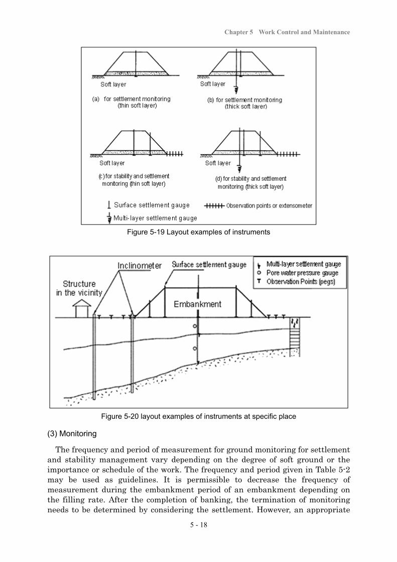
Chapter 5 Work Control and Maintenance
5 - 18
Figure 5-19 Layout examples of instruments
Figure 5-20 layout examples of instruments at specific place
(3) Monitoring
The frequency and period of measurement for ground monitoring for settlement and stability management vary depending on the degree of soft ground or the importance or schedule of the work. The frequency and period given in Table 5-2 may be used as guidelines. It is permissible to decrease the frequency of measurement during the embankment period of an embankment depending on the filling rate. After the completion of banking, the termination of monitoring needs to be determined by considering the settlement. However, an appropriate
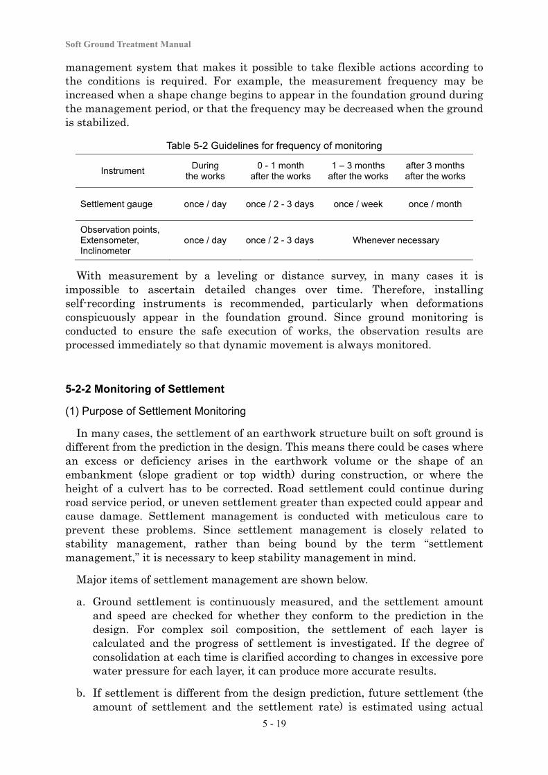
Soft Ground Treatment Manual
5 - 19
management system that makes it possible to take flexible actions according to the conditions is required. For example, the measurement frequency may be increased when a shape change begins to appear in the foundation ground during the management period, or that the frequency may be decreased when the ground is stabilized.
Table 5-2 Guidelines for frequency of monitoring
Instrument During
the works 0 - 1 month
after the works1 – 3 months
after the works after 3 months after the works
Settlement gauge once / day once / 2 - 3 days once / week once / month
Observation points, Extensometer, Inclinometer
once / day once / 2 - 3 days Whenever necessary
With measurement by a leveling or distance survey, in many cases it is impossible to ascertain detailed changes over time. Therefore, installing self-recording instruments is recommended, particularly when deformations conspicuously appear in the foundation ground. Since ground monitoring is conducted to ensure the safe execution of works, the observation results are processed immediately so that dynamic movement is always monitored.
5-2-2 Monitoring of Settlement
(1) Purpose of Settlement Monitoring
In many cases, the settlement of an earthwork structure built on soft ground is different from the prediction in the design. This means there could be cases where an excess or deficiency arises in the earthwork volume or the shape of an embankment (slope gradient or top width) during construction, or where the height of a culvert has to be corrected. Road settlement could continue during road service period, or uneven settlement greater than expected could appear and cause damage. Settlement management is conducted with meticulous care to prevent these problems. Since settlement management is closely related to stability management, rather than being bound by the term “settlement management,” it is necessary to keep stability management in mind.
Major items of settlement management are shown below.
a. Ground settlement is continuously measured, and the settlement amount and speed are checked for whether they conform to the prediction in the design. For complex soil composition, the settlement of each layer is calculated and the progress of settlement is investigated. If the degree of consolidation at each time is clarified according to changes in excessive pore water pressure for each layer, it can produce more accurate results.
b. If settlement is different from the design prediction, future settlement (the amount of settlement and the settlement rate) is estimated using actual
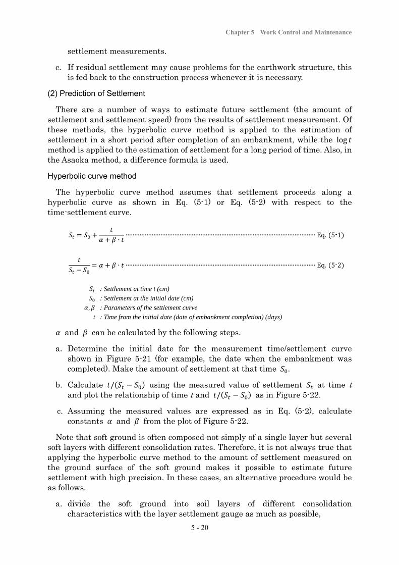
Chapter 5 Work Control and Maintenance
5 - 20
settlement measurements.
c. If residual settlement may cause problems for the earthwork structure, this is fed back to the construction process whenever it is necessary.
(2) Prediction of Settlement
There are a number of ways to estimate future settlement (the amount of settlement and settlement speed) from the results of settlement measurement. Of these methods, the hyperbolic curve method is applied to the estimation of settlement in a short period after completion of an embankment, while the log method is applied to the estimation of settlement for a long period of time. Also, in the Asaoka method, a difference formula is used.
Hyperbolic curve method
The hyperbolic curve method assumes that settlement proceeds along a hyperbolic curve as shown in Eq. (5-1) or Eq. (5-2) with respect to the time-settlement curve.
∙∙∙∙∙∙∙∙∙∙∙∙∙∙∙∙∙∙∙∙∙∙∙∙∙∙∙∙∙∙∙∙∙∙∙∙∙∙∙∙∙∙∙∙∙∙∙∙∙∙∙∙∙∙∙∙∙∙∙∙∙∙∙∙∙∙∙∙∙∙∙∙∙∙∙∙∙∙∙∙∙∙∙∙∙∙∙∙∙∙∙∙∙∙∙∙∙∙∙∙∙∙∙∙∙∙∙∙∙∙ Eq. 5-1
∙ ∙∙∙∙∙∙∙∙∙∙∙∙∙∙∙∙∙∙∙∙∙∙∙∙∙∙∙∙∙∙∙∙∙∙∙∙∙∙∙∙∙∙∙∙∙∙∙∙∙∙∙∙∙∙∙∙∙∙∙∙∙∙∙∙∙∙∙∙∙∙∙∙∙∙∙∙∙∙∙∙∙∙∙∙∙∙∙∙∙∙∙∙∙∙∙∙∙∙∙∙∙∙∙∙∙∙∙∙∙ Eq. 5-2
: Settlement at time t (cm)
: Settlement at the initial date (cm)
, : Parameters of the settlement curve
t : Time from the initial date (date of embankment completion) (days)
and can be calculated by the following steps.
a. Determine the initial date for the measurement time/settlement curve shown in Figure 5-21 (for example, the date when the embankment was completed). Make the amount of settlement at that time .
b. Calculate / using the measured value of settlement at time t and plot the relationship of time t and / as in Figure 5-22.
c. Assuming the measured values are expressed as in Eq. (5-2), calculate constants and from the plot of Figure 5-22.
Note that soft ground is often composed not simply of a single layer but several soft layers with different consolidation rates. Therefore, it is not always true that applying the hyperbolic curve method to the amount of settlement measured on the ground surface of the soft ground makes it possible to estimate future settlement with high precision. In these cases, an alternative procedure would be as follows.
a. divide the soft ground into soil layers of different consolidation characteristics with the layer settlement gauge as much as possible,
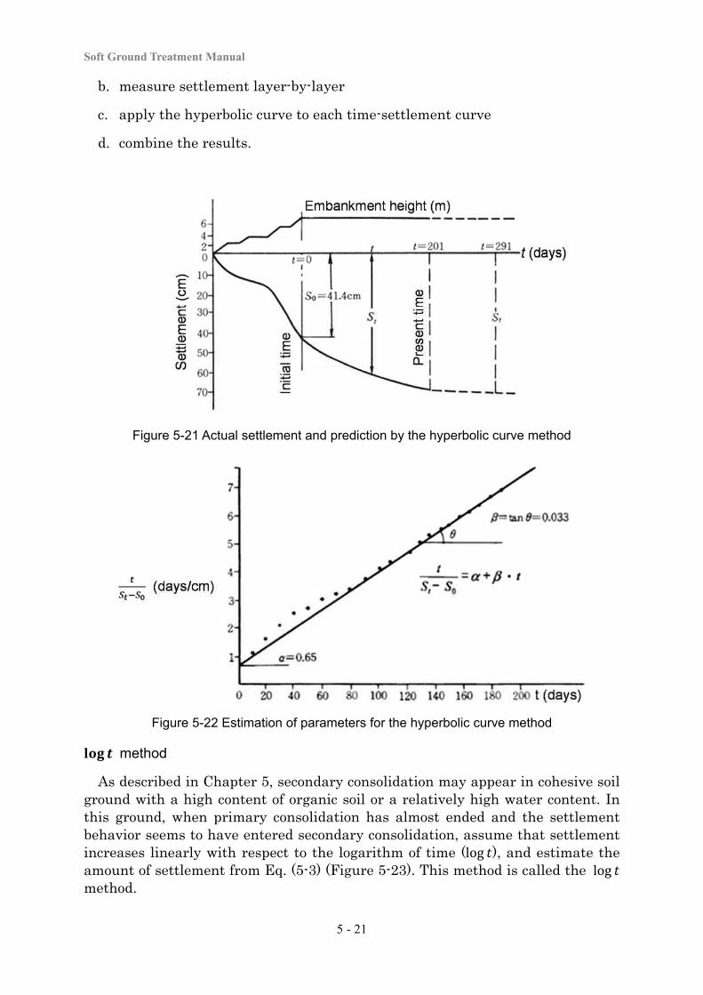
Soft Ground Treatment Manual
5 - 21
b. measure settlement layer-by-layer
c. apply the hyperbolic curve to each time-settlement curve
d. combine the results.
Figure 5-21 Actual settlement and prediction by the hyperbolic curve method
Figure 5-22 Estimation of parameters for the hyperbolic curve method
method
As described in Chapter 5, secondary consolidation may appear in cohesive soil ground with a high content of organic soil or a relatively high water content. In this ground, when primary consolidation has almost ended and the settlement behavior seems to have entered secondary consolidation, assume that settlement increases linearly with respect to the logarithm of time (log ), and estimate the amount of settlement from Eq. (5-3) (Figure 5-23). This method is called the log
method.
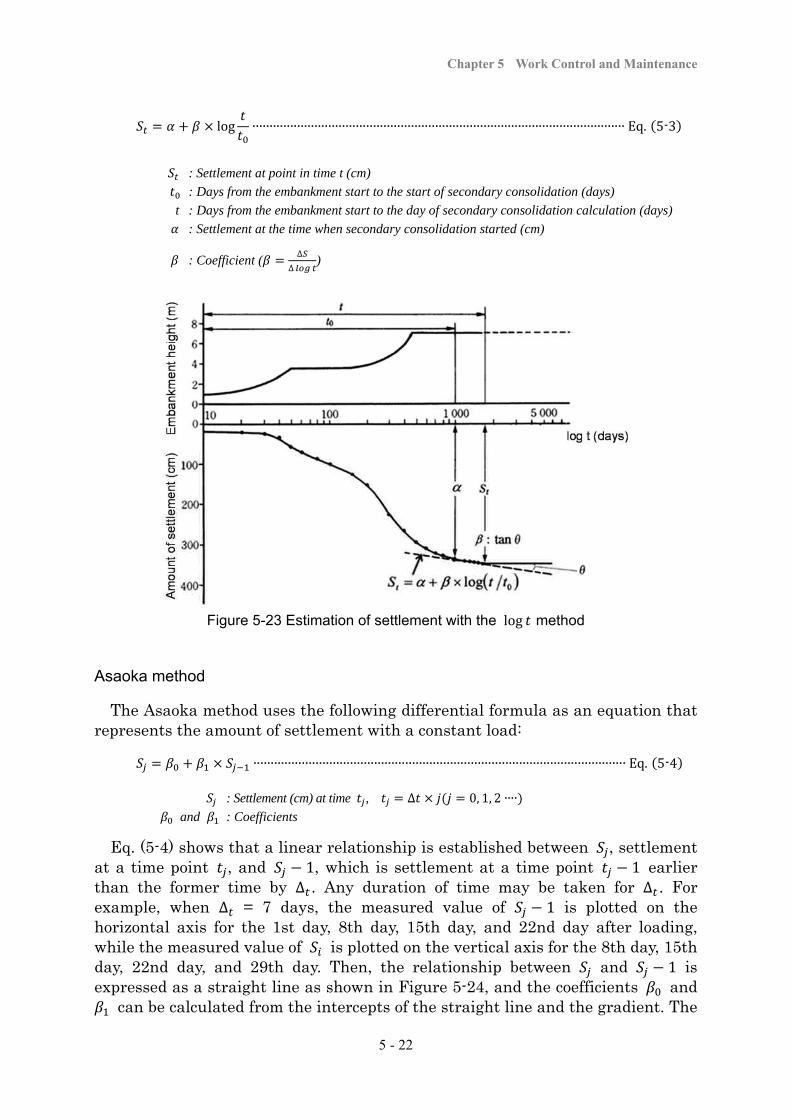
Chapter 5 Work Control and Maintenance
5 - 22
log ∙∙∙∙∙∙∙∙∙∙∙∙∙∙∙∙∙∙∙∙∙∙∙∙∙∙∙∙∙∙∙∙∙∙∙∙∙∙∙∙∙∙∙∙∙∙∙∙∙∙∙∙∙∙∙∙∙∙∙∙∙∙∙∙∙∙∙∙∙∙∙∙∙∙∙∙∙∙∙∙∙∙∙∙∙∙∙∙∙∙∙∙∙∙∙∙∙∙∙∙∙∙∙∙∙∙∙∙ Eq. 5-3
: Settlement at point in time t (cm)
: Days from the embankment start to the start of secondary consolidation (days)
t : Days from the embankment start to the day of secondary consolidation calculation (days)
: Settlement at the time when secondary consolidation started (cm)
: Coefficient (∆
∆)
Figure 5-23 Estimation of settlement with the log method
Asaoka method
The Asaoka method uses the following differential formula as an equation that represents the amount of settlement with a constant load:
∙∙∙∙∙∙∙∙∙∙∙∙∙∙∙∙∙∙∙∙∙∙∙∙∙∙∙∙∙∙∙∙∙∙∙∙∙∙∙∙∙∙∙∙∙∙∙∙∙∙∙∙∙∙∙∙∙∙∙∙∙∙∙∙∙∙∙∙∙∙∙∙∙∙∙∙∙∙∙∙∙∙∙∙∙∙∙∙∙∙∙∙∙∙∙∙∙∙∙∙∙∙∙∙∙∙∙∙ Eq. 5-4
: Settlement (cm) at time , ∆ 0, 1, 2 ∙∙∙∙
and : Coefficients
Eq. (5-4) shows that a linear relationship is established between , settlement at a time point , and 1, which is settlement at a time point 1 earlier than the former time by ∆ . Any duration of time may be taken for ∆ . For example, when ∆ = 7 days, the measured value of 1 is plotted on the horizontal axis for the 1st day, 8th day, 15th day, and 22nd day after loading, while the measured value of is plotted on the vertical axis for the 8th day, 15th day, 22nd day, and 29th day. Then, the relationship between and 1 is expressed as a straight line as shown in Figure 5-24, and the coefficients and
can be calculated from the intercepts of the straight line and the gradient. The
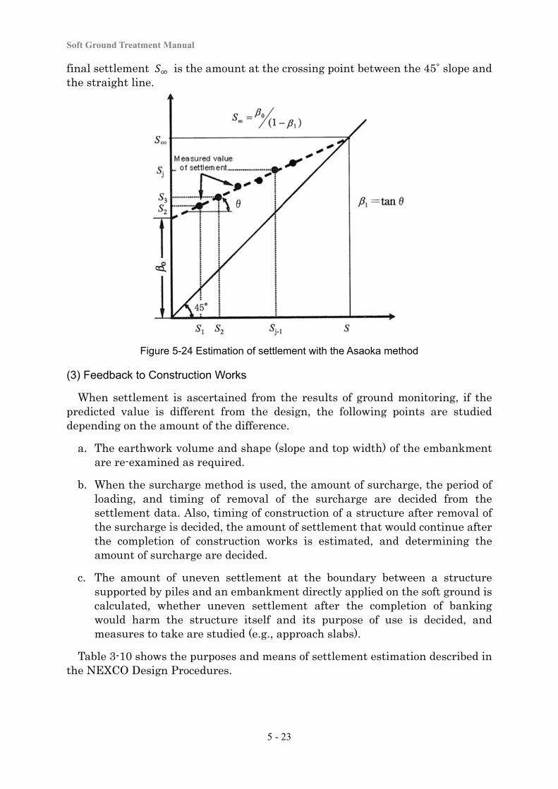
Soft Ground Treatment Manual
5 - 23
final settlement is the amount at the crossing point between the 45˚ slope and the straight line.
Figure 5-24 Estimation of settlement with the Asaoka method
(3) Feedback to Construction Works
When settlement is ascertained from the results of ground monitoring, if the predicted value is different from the design, the following points are studied depending on the amount of the difference.
a. The earthwork volume and shape (slope and top width) of the embankment are re-examined as required.
b. When the surcharge method is used, the amount of surcharge, the period of loading, and timing of removal of the surcharge are decided from the settlement data. Also, timing of construction of a structure after removal of the surcharge is decided, the amount of settlement that would continue after the completion of construction works is estimated, and determining the amount of surcharge are decided.
c. The amount of uneven settlement at the boundary between a structure supported by piles and an embankment directly applied on the soft ground is calculated, whether uneven settlement after the completion of banking would harm the structure itself and its purpose of use is decided, and measures to take are studied (e.g., approach slabs).
Table 3-10 shows the purposes and means of settlement estimation described in the NEXCO Design Procedures.
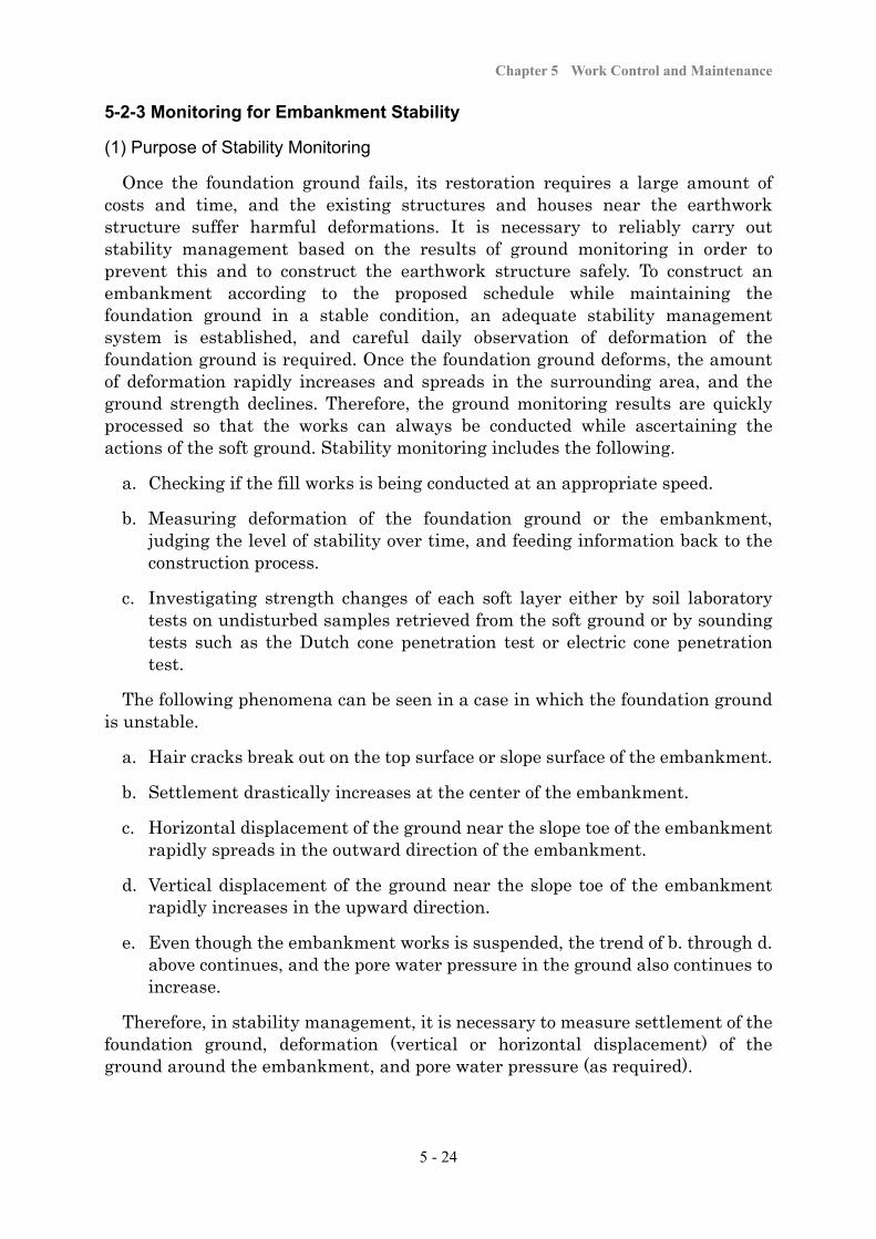
Chapter 5 Work Control and Maintenance
5 - 24
5-2-3 Monitoring for Embankment Stability
(1) Purpose of Stability Monitoring
Once the foundation ground fails, its restoration requires a large amount of costs and time, and the existing structures and houses near the earthwork structure suffer harmful deformations. It is necessary to reliably carry out stability management based on the results of ground monitoring in order to prevent this and to construct the earthwork structure safely. To construct an embankment according to the proposed schedule while maintaining the foundation ground in a stable condition, an adequate stability management system is established, and careful daily observation of deformation of the foundation ground is required. Once the foundation ground deforms, the amount of deformation rapidly increases and spreads in the surrounding area, and the ground strength declines. Therefore, the ground monitoring results are quickly processed so that the works can always be conducted while ascertaining the actions of the soft ground. Stability monitoring includes the following.
a. Checking if the fill works is being conducted at an appropriate speed.
b. Measuring deformation of the foundation ground or the embankment, judging the level of stability over time, and feeding information back to the construction process.
c. Investigating strength changes of each soft layer either by soil laboratory tests on undisturbed samples retrieved from the soft ground or by sounding tests such as the Dutch cone penetration test or electric cone penetration test.
The following phenomena can be seen in a case in which the foundation ground is unstable.
a. Hair cracks break out on the top surface or slope surface of the embankment.
b. Settlement drastically increases at the center of the embankment.
c. Horizontal displacement of the ground near the slope toe of the embankment rapidly spreads in the outward direction of the embankment.
d. Vertical displacement of the ground near the slope toe of the embankment rapidly increases in the upward direction.
e. Even though the embankment works is suspended, the trend of b. through d. above continues, and the pore water pressure in the ground also continues to increase.
Therefore, in stability management, it is necessary to measure settlement of the foundation ground, deformation (vertical or horizontal displacement) of the ground around the embankment, and pore water pressure (as required).
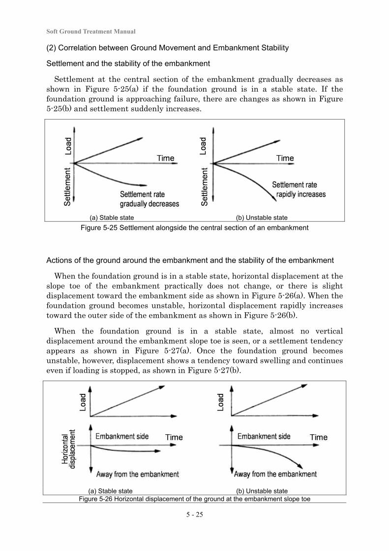
Soft Ground Treatment Manual
5 - 25
(2) Correlation between Ground Movement and Embankment Stability
Settlement and the stability of the embankment
Settlement at the central section of the embankment gradually decreases as shown in Figure 5-25(a) if the foundation ground is in a stable state. If the foundation ground is approaching failure, there are changes as shown in Figure 5-25(b) and settlement suddenly increases.
(a) Stable state (b) Unstable state
Figure 5-25 Settlement alongside the central section of an embankment
Actions of the ground around the embankment and the stability of the embankment
When the foundation ground is in a stable state, horizontal displacement at the slope toe of the embankment practically does not change, or there is slight displacement toward the embankment side as shown in Figure 5-26(a). When the foundation ground becomes unstable, horizontal displacement rapidly increases toward the outer side of the embankment as shown in Figure 5-26(b).
When the foundation ground is in a stable state, almost no vertical displacement around the embankment slope toe is seen, or a settlement tendency appears as shown in Figure 5-27(a). Once the foundation ground becomes unstable, however, displacement shows a tendency toward swelling and continues even if loading is stopped, as shown in Figure 5-27(b).
(a) Stable state (b) Unstable state Figure 5-26 Horizontal displacement of the ground at the embankment slope toe
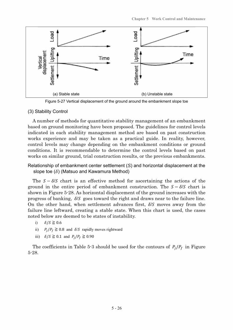
Chapter 5 Work Control and Maintenance
5 - 26
(a) Stable state (b) Unstable state
Figure 5-27 Vertical displacement of the ground around the embankment slope toe
(3) Stability Control
A number of methods for quantitative stability management of an embankment based on ground monitoring have been proposed. The guidelines for control levels indicated in each stability management method are based on past construction works experience and may be taken as a practical guide. In reality, however, control levels may change depending on the embankment conditions or ground conditions. It is recommendable to determine the control levels based on past works on similar ground, trial construction results, or the previous embankments.
Relationship of embankment center settlement (S) and horizontal displacement at the slope toe ( ) (Matsuo and Kawamura Method)
The / chart is an effective method for ascertaining the actions of the ground in the entire period of embankment construction. The / chart is shown in Figure 5-28. As horizontal displacement of the ground increases with the progress of banking, / goes toward the right and draws near to the failure line. On the other hand, when settlement advances first, / moves away from the failure line leftward, creating a stable state. When this chart is used, the cases noted below are deemed to be states of instability.
i) / ≧ 0.6
ii) / ≧ 0.8 and / rapidly moves rightward
iii) / ≧ 0.1 and / ≧ 0.90
The coefficients in Table 5-3 should be used for the contours of / in Figure 5-28.
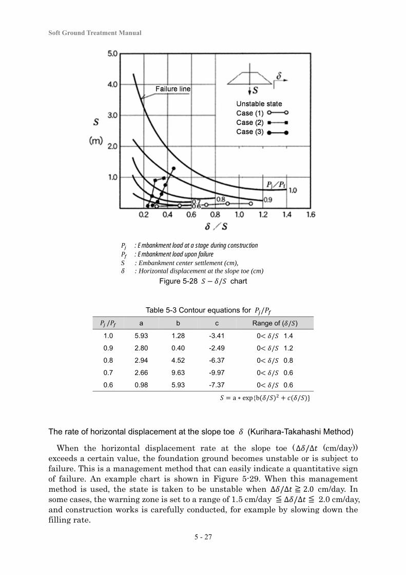
Soft Ground Treatment Manual
5 - 27
: Embankment load at a stage during construction : Embankment load upon failure
S : Embankment center settlement (cm), : Horizontal displacement at the slope toe (cm)
Figure 5-28 / chart
Table 5-3 Contour equations for /
/ a b c Range of ( / )
1.0 5.93 1.28 -3.41 0 / 1.4
0.9 2.80 0.40 -2.49 0 / 1.2
0.8 2.94 4.52 -6.37 0 / 0.8
0.7 2.66 9.63 -9.97 0 / 0.6
0.6 0.98 5.93 -7.37 0 / 0.6
a ∗ exp{b / /
The rate of horizontal displacement at the slope toe (Kurihara-Takahashi Method)
When the horizontal displacement rate at the slope toe (∆ /∆ (cm/day)) exceeds a certain value, the foundation ground becomes unstable or is subject to failure. This is a management method that can easily indicate a quantitative sign of failure. An example chart is shown in Figure 5-29. When this management method is used, the state is taken to be unstable when ∆ /∆ ≧ 2.0 cm/day. In some cases, the warning zone is set to a range of 1.5 cm/day ≦ ∆ /∆ ≦ 2.0 cm/day, and construction works is carefully conducted, for example by slowing down the filling rate.
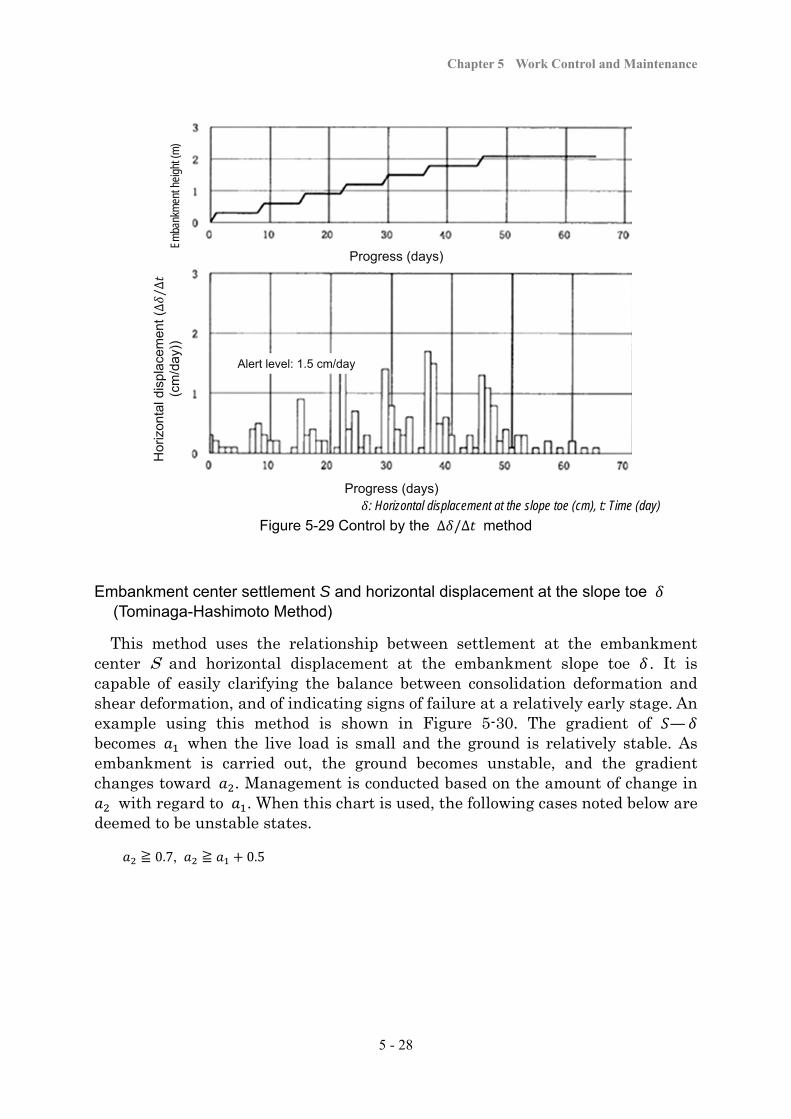
Chapter 5 Work Control and Maintenance
5 - 28
: Horizontal displacement at the slope toe (cm), t: Time (day)
Figure 5-29 Control by the ∆ /∆ method
Embankment center settlement S and horizontal displacement at the slope toe (Tominaga-Hashimoto Method)
This method uses the relationship between settlement at the embankment center S and horizontal displacement at the embankment slope toe . It is capable of easily clarifying the balance between consolidation deformation and shear deformation, and of indicating signs of failure at a relatively early stage. An example using this method is shown in Figure 5-30. The gradient of — becomes when the live load is small and the ground is relatively stable. As embankment is carried out, the ground becomes unstable, and the gradient changes toward . Management is conducted based on the amount of change in
with regard to . When this chart is used, the following cases noted below are deemed to be unstable states.
≧ 0.7, ≧ 0.5
Emba
nkm
ent h
eigh
t (m
)
Progress (days)
Hor
izon
tal d
ispl
acem
ent (∆/∆
(c
m/d
ay))
Alert level: 1.5 cm/day
Progress (days)
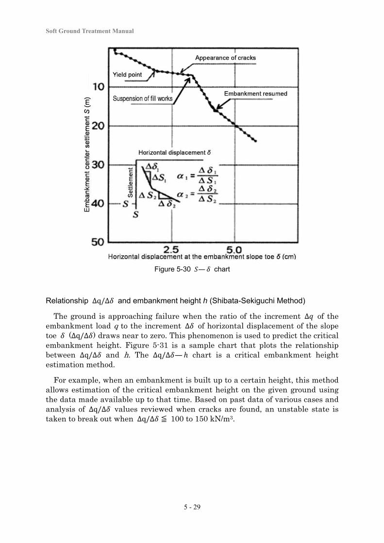
Soft Ground Treatment Manual
5 - 29
Figure 5-30 — chart
Relationship ∆q/∆ and embankment height h (Shibata-Sekiguchi Method)
The ground is approaching failure when the ratio of the increment ∆ of the embankment load q to the increment ∆ of horizontal displacement of the slope toe (∆q/∆ ) draws near to zero. This phenomenon is used to predict the critical embankment height. Figure 5-31 is a sample chart that plots the relationship between ∆q/∆ and h. The ∆q/∆ — chart is a critical embankment height estimation method.
For example, when an embankment is built up to a certain height, this method allows estimation of the critical embankment height on the given ground using the data made available up to that time. Based on past data of various cases and analysis of ∆q/∆ values reviewed when cracks are found, an unstable state is taken to break out when ∆q/∆ ≦ 100 to 150 kN/m3.
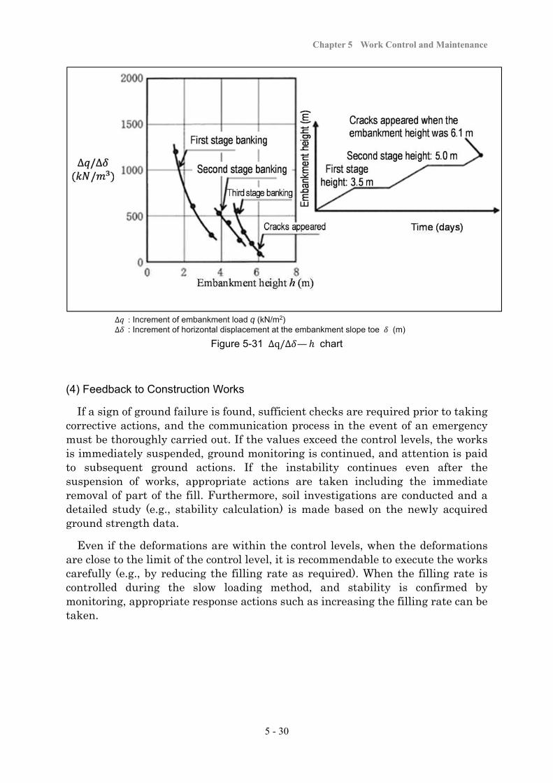
Chapter 5 Work Control and Maintenance
5 - 30
∆ : Increment of embankment load q (kN/m2) ∆ : Increment of horizontal displacement at the embankment slope toe (m)
Figure 5-31 ∆q/∆ — chart
(4) Feedback to Construction Works
If a sign of ground failure is found, sufficient checks are required prior to taking corrective actions, and the communication process in the event of an emergency must be thoroughly carried out. If the values exceed the control levels, the works is immediately suspended, ground monitoring is continued, and attention is paid to subsequent ground actions. If the instability continues even after the suspension of works, appropriate actions are taken including the immediate removal of part of the fill. Furthermore, soil investigations are conducted and a detailed study (e.g., stability calculation) is made based on the newly acquired ground strength data.
Even if the deformations are within the control levels, when the deformations are close to the limit of the control level, it is recommendable to execute the works carefully (e.g., by reducing the filling rate as required). When the filling rate is controlled during the slow loading method, and stability is confirmed by monitoring, appropriate response actions such as increasing the filling rate can be taken.
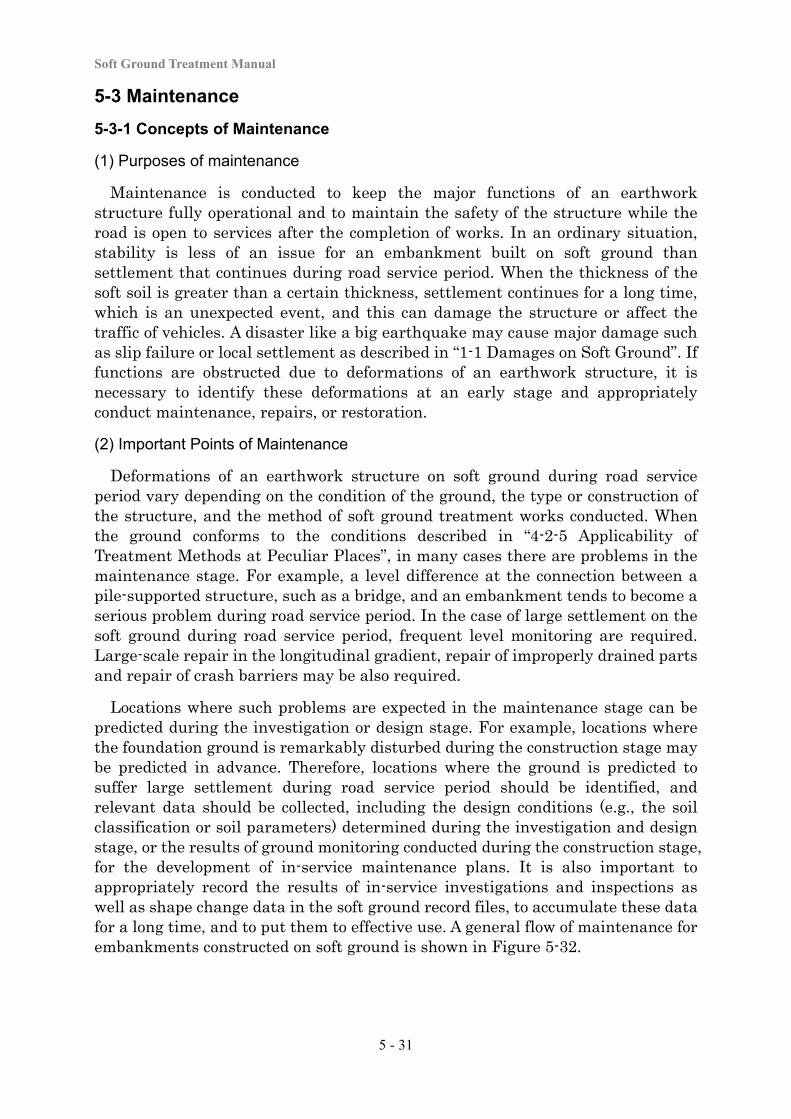
Soft Ground Treatment Manual
5 - 31
5-3 Maintenance
5-3-1 Concepts of Maintenance
(1) Purposes of maintenance
Maintenance is conducted to keep the major functions of an earthwork structure fully operational and to maintain the safety of the structure while the road is open to services after the completion of works. In an ordinary situation, stability is less of an issue for an embankment built on soft ground than settlement that continues during road service period. When the thickness of the soft soil is greater than a certain thickness, settlement continues for a long time, which is an unexpected event, and this can damage the structure or affect the traffic of vehicles. A disaster like a big earthquake may cause major damage such as slip failure or local settlement as described in “1-1 Damages on Soft Ground”. If functions are obstructed due to deformations of an earthwork structure, it is necessary to identify these deformations at an early stage and appropriately conduct maintenance, repairs, or restoration.
(2) Important Points of Maintenance
Deformations of an earthwork structure on soft ground during road service period vary depending on the condition of the ground, the type or construction of the structure, and the method of soft ground treatment works conducted. When the ground conforms to the conditions described in “4-2-5 Applicability of Treatment Methods at Peculiar Places”, in many cases there are problems in the maintenance stage. For example, a level difference at the connection between a pile-supported structure, such as a bridge, and an embankment tends to become a serious problem during road service period. In the case of large settlement on the soft ground during road service period, frequent level monitoring are required. Large-scale repair in the longitudinal gradient, repair of improperly drained parts and repair of crash barriers may be also required.
Locations where such problems are expected in the maintenance stage can be predicted during the investigation or design stage. For example, locations where the foundation ground is remarkably disturbed during the construction stage may be predicted in advance. Therefore, locations where the ground is predicted to suffer large settlement during road service period should be identified, and relevant data should be collected, including the design conditions (e.g., the soil classification or soil parameters) determined during the investigation and design stage, or the results of ground monitoring conducted during the construction stage, for the development of in-service maintenance plans. It is also important to appropriately record the results of in-service investigations and inspections as well as shape change data in the soft ground record files, to accumulate these data for a long time, and to put them to effective use. A general flow of maintenance for embankments constructed on soft ground is shown in Figure 5-32.
Chapter 5 Work Control and Maintenance
5 - 32
Figure 5-32 Flow of maintenance
5-3-2 Regular Inspection and Emergency Inspection
(1) Inspection
Daily inspections
Daily inspections for soft ground are conducted to quickly discover deformations of the pavement and earthwork structures, to determine the appropriate response to these changes, and to decide the necessity of repairs. These inspections are usually conducted as observations from aboard a vehicle. The main inspection points are deformations unique to soft ground, irregularities or cracks on the pavement surface, and cracks or swelling on slope tops or slope surfaces. The special attention are required in the inspection at the locations where there were problems during construction, where large settlement appeared during road service period, or where surface unevenness suddenly progressed
Attention should also be paid to the presence of abutment movement due to eccentric earth pressure or the amount, size, or deformations of cracks in concrete structures due to uneven settlement. Inspection of such places requires particularly careful attention if they require a precondition of repair in the maintenance stage as explained in “4-2-6 Mitigation of Long-term Residual Settlement”.
Emergency inspections
In a disaster, (e.g., a major earthquake), conducting emergency inspections is important to minimize the impact on the traffic functions and the roadside areas.
Soft Ground Treatment Manual
5 - 33
Emergency inspections are conducted and completed as quickly as possible, with a special focus on cracks on the road surface, deformations of drainage facilities or level differences on the road surfaces due to uneven settlement, and deformations in the surrounding ground or structures located close to the earthwork structures.
(2) Points in inspections
Locations with low embankments
Where an embankment is low, the traffic loads have a big influence on the foundation ground. There are many cases such as uneven settlement or cracking on the road surface due to the difference in soft layer thicknesses or the difference in the properties of the soils that constitute the soft layers. If the road surface is not flat, the level of noise or vibration generated due to traffic can become large enough to disturb roadside areas
Connections between pile-supported structures (e.g., bridges) and embankments
The road surfaces at the connections between pile-supported structures and embankments are particularly prone to level differences because of the difference in the amount of settlement during road service period. There may be cavities at a level difference section where concrete pavement was laid or where approach slabs were installed. These cavities can be found by careful inspections, as they cause changes in traffic noise or impact noise generated due to traffic.
Road crossing structures and underground structures
Road crossing structures, such as structures for dedicated road use or culverts used for water channels, or underground structures located inside or close to embankments, tend to suffer from insufficiency in the cross-section or drainage malfunction due to continuing settlement even during road service period. Therefore, the presence and progress of deformations in crossing structures or underground structures are observed, and the degree of harmful influence on their functions is checked.
Impact on the surrounding ground
The ground may settle due to the load of the embankment, which can affect fields or drainage facilities in the vicinity, and the degree of this impact is an inspection item.
5-3-3 Investigation
When a shape change or damage is found or predicted by a daily inspection or emergency inspection in the maintenance stage, an investigation is conducted to decide the necessity of repairs or restoration, to select treatment methods, or to review execution methods. The investigation involves;
a. checking the causes of any deformations found by observations during inspections,
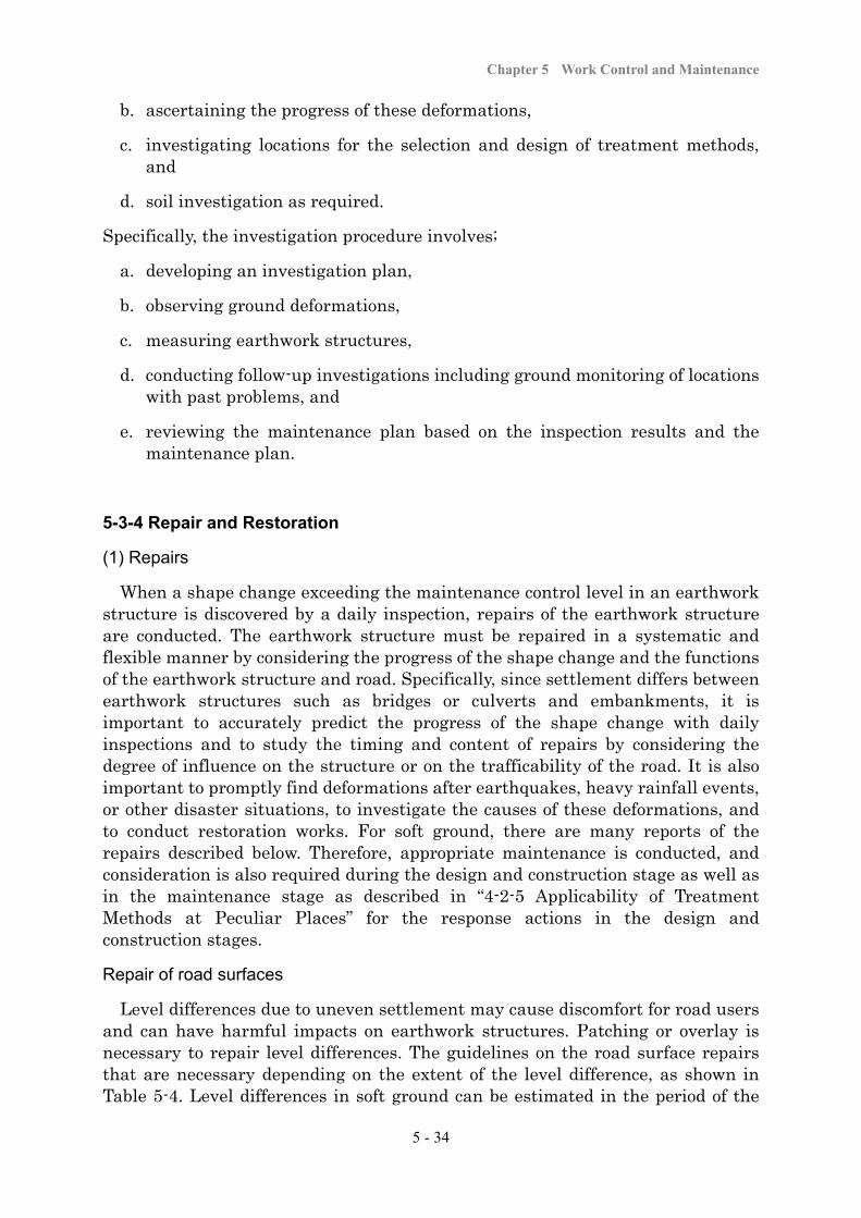
Chapter 5 Work Control and Maintenance
5 - 34
b. ascertaining the progress of these deformations,
c. investigating locations for the selection and design of treatment methods, and
d. soil investigation as required.
Specifically, the investigation procedure involves;
a. developing an investigation plan,
b. observing ground deformations,
c. measuring earthwork structures,
d. conducting follow-up investigations including ground monitoring of locations with past problems, and
e. reviewing the maintenance plan based on the inspection results and the maintenance plan.
5-3-4 Repair and Restoration
(1) Repairs
When a shape change exceeding the maintenance control level in an earthwork structure is discovered by a daily inspection, repairs of the earthwork structure are conducted. The earthwork structure must be repaired in a systematic and flexible manner by considering the progress of the shape change and the functions of the earthwork structure and road. Specifically, since settlement differs between earthwork structures such as bridges or culverts and embankments, it is important to accurately predict the progress of the shape change with daily inspections and to study the timing and content of repairs by considering the degree of influence on the structure or on the trafficability of the road. It is also important to promptly find deformations after earthquakes, heavy rainfall events, or other disaster situations, to investigate the causes of these deformations, and to conduct restoration works. For soft ground, there are many reports of the repairs described below. Therefore, appropriate maintenance is conducted, and consideration is also required during the design and construction stage as well as in the maintenance stage as described in “4-2-5 Applicability of Treatment Methods at Peculiar Places” for the response actions in the design and construction stages.
Repair of road surfaces
Level differences due to uneven settlement may cause discomfort for road users and can have harmful impacts on earthwork structures. Patching or overlay is necessary to repair level differences. The guidelines on the road surface repairs that are necessary depending on the extent of the level difference, as shown in Table 5-4. Level differences in soft ground can be estimated in the period of the

Soft Ground Treatment Manual
5 - 35
first five years during road service period. Therefore, it is necessary to pay attention to maintenance and repairs from the start of opening to services.
Table 5-4 Criterion levels of repair
Road TypeLevel gap (mm)
Bridge Culvert
Expressway 20 30
Road with heavy traffic 30 40
Road with light traffic 30 -
Repair of cavities under approach slabs
When large cavities are found under an approach slab, in some cases they should be filled with liquid concrete, or dried sand or crushed stone. Therefore, it is recommendable to make holes in advance in a few locations in the approach slabs for filling.
Settlement of the surrounding ground due to the embankment load
Settlement in the surrounding ground due to the load of the embankment generally affects a width that is about one to two times the thickness of the soft layer. If the surrounding area is farmland, common solutions would be to replace the ground with soil brought in from elsewhere, or to perform smoothing or other soil improvement.
Figure 5-33 Settlement of surrounding ground caused by embankment load
Repair of drainage facilities
If uneven settlement prevents the attainment of the intended longitudinal or transverse gradient and this causes problems to drainage on the road surface or roadside areas, repairs are quickly conducted (Figures 4-33 and 5-34). For a road with a divider, larger settlement may be closer to the divider, and the water channel constructed in the divider may be damaged or water flow in the channel may become poor. In such cases, large-scale repair works is necessary, and thus sufficient attention must be paid in the construction stage, such as by installing a water channel after taking preventive measures such as the application of surcharge loads. In water channel construction, for ease of repairs, it is recommendable to be plan for the impact of settlement.
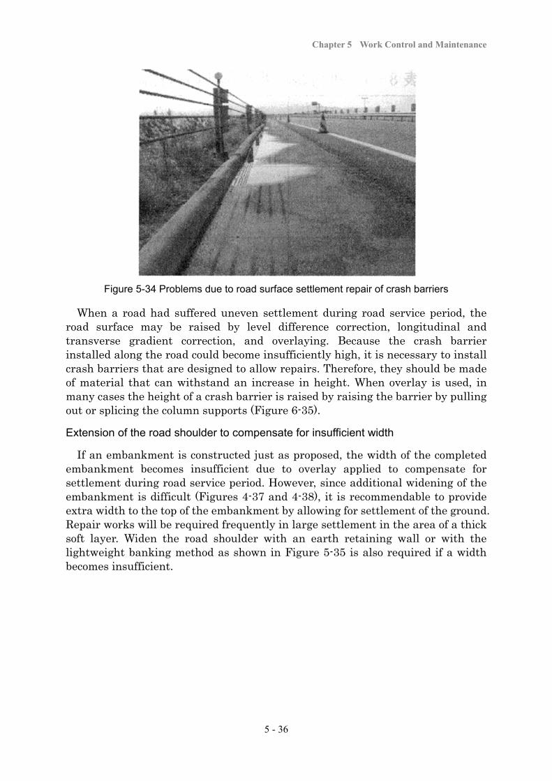
Chapter 5 Work Control and Maintenance
5 - 36
Figure 5-34 Problems due to road surface settlement repair of crash barriers
When a road had suffered uneven settlement during road service period, the road surface may be raised by level difference correction, longitudinal and transverse gradient correction, and overlaying. Because the crash barrier installed along the road could become insufficiently high, it is necessary to install crash barriers that are designed to allow repairs. Therefore, they should be made of material that can withstand an increase in height. When overlay is used, in many cases the height of a crash barrier is raised by raising the barrier by pulling out or splicing the column supports (Figure 6-35).
Extension of the road shoulder to compensate for insufficient width
If an embankment is constructed just as proposed, the width of the completed embankment becomes insufficient due to overlay applied to compensate for settlement during road service period. However, since additional widening of the embankment is difficult (Figures 4-37 and 4-38), it is recommendable to provide extra width to the top of the embankment by allowing for settlement of the ground. Repair works will be required frequently in large settlement in the area of a thick soft layer. Widen the road shoulder with an earth retaining wall or with the lightweight banking method as shown in Figure 5-35 is also required if a width becomes insufficient.

Soft Ground Treatment Manual
5 - 37
(a) Widening with a retaining wall (b) Widening with a lightweight embankment
Figure 5-35 Widening of the road shoulder to compensate for insufficient width
(2) Rehabilitation of Earthquake Disaster
In recent years, large-scale damage to earthwork structures due to earthquakes has been characterized mainly by the followings.
a. the liquefaction of landfill ground
b. the liquefaction of backfill for conduits, etc.
c. strength reduction after an earthquake of embankments in geomorphologic concave areas
d. the liquefaction of banking material that became saturated as an embankment on soft ground settled to below the groundwater level
It must be noted that not only natural ground but also artificial ground is subject to liquefaction.
5-3-5 Restoration
(1) Investigation necessary for restoration measures
If the foundation ground has failed, it is necessary to sufficiently study the actual conditions and the cause of the failure and implement restoration measures based on the results. An appropriate method of investigation that can be carried out quickly and efficiently is selected in order to swiftly and accurately ascertain the status and range of the failure, to analyze the cause of the failure, and to take appropriate actions.
Understanding the status and range of the failure
Observations that are as detailed as possible are performed on the location and size of cracks or the amount of deformation on the embankment or its surrounding ground. It is also necessary to check relevant information including external conditions such as rainfall, the progress of the work or the process of deformation until the ground failed, and the embankment works including the embankment height or the method of spreading. The amount of deformation or the range of
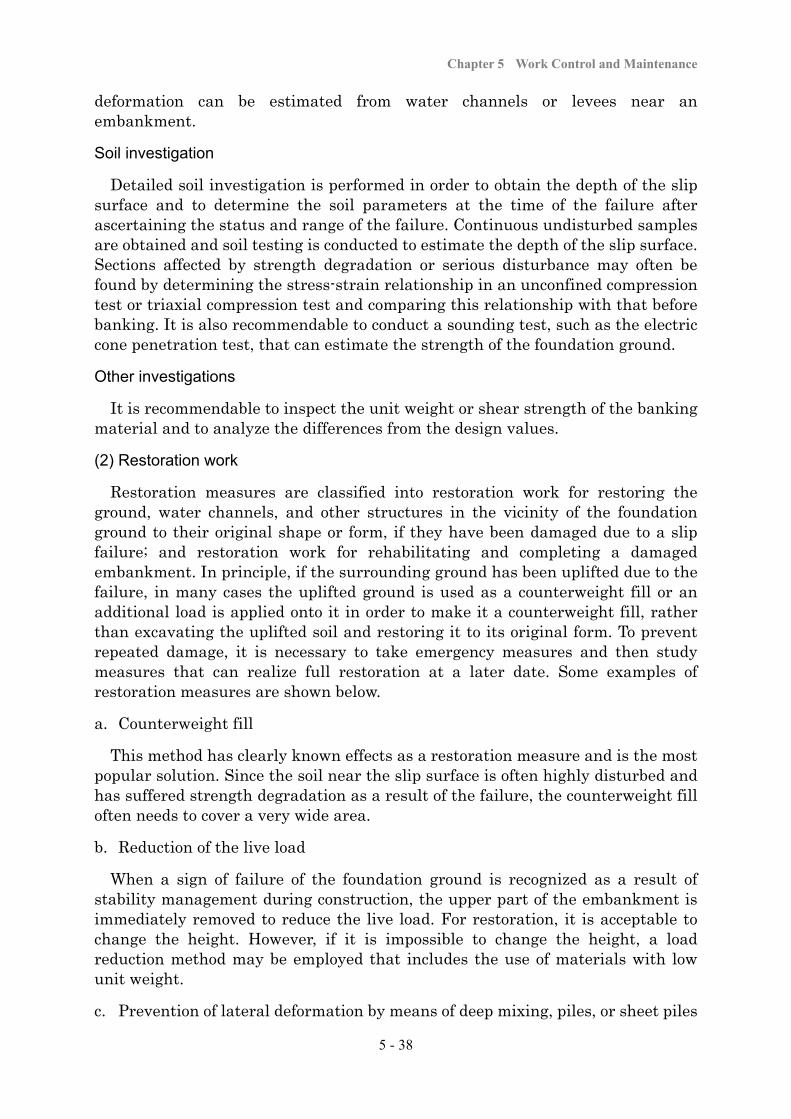
Chapter 5 Work Control and Maintenance
5 - 38
deformation can be estimated from water channels or levees near an embankment.
Soil investigation
Detailed soil investigation is performed in order to obtain the depth of the slip surface and to determine the soil parameters at the time of the failure after ascertaining the status and range of the failure. Continuous undisturbed samples are obtained and soil testing is conducted to estimate the depth of the slip surface. Sections affected by strength degradation or serious disturbance may often be found by determining the stress-strain relationship in an unconfined compression test or triaxial compression test and comparing this relationship with that before banking. It is also recommendable to conduct a sounding test, such as the electric cone penetration test, that can estimate the strength of the foundation ground.
Other investigations
It is recommendable to inspect the unit weight or shear strength of the banking material and to analyze the differences from the design values.
(2) Restoration work
Restoration measures are classified into restoration work for restoring the ground, water channels, and other structures in the vicinity of the foundation ground to their original shape or form, if they have been damaged due to a slip failure; and restoration work for rehabilitating and completing a damaged embankment. In principle, if the surrounding ground has been uplifted due to the failure, in many cases the uplifted ground is used as a counterweight fill or an additional load is applied onto it in order to make it a counterweight fill, rather than excavating the uplifted soil and restoring it to its original form. To prevent repeated damage, it is necessary to take emergency measures and then study measures that can realize full restoration at a later date. Some examples of restoration measures are shown below.
a. Counterweight fill
This method has clearly known effects as a restoration measure and is the most popular solution. Since the soil near the slip surface is often highly disturbed and has suffered strength degradation as a result of the failure, the counterweight fill often needs to cover a very wide area.
b. Reduction of the live load
When a sign of failure of the foundation ground is recognized as a result of stability management during construction, the upper part of the embankment is immediately removed to reduce the live load. For restoration, it is acceptable to change the height. However, if it is impossible to change the height, a load reduction method may be employed that includes the use of materials with low unit weight.
c. Prevention of lateral deformation by means of deep mixing, piles, or sheet piles
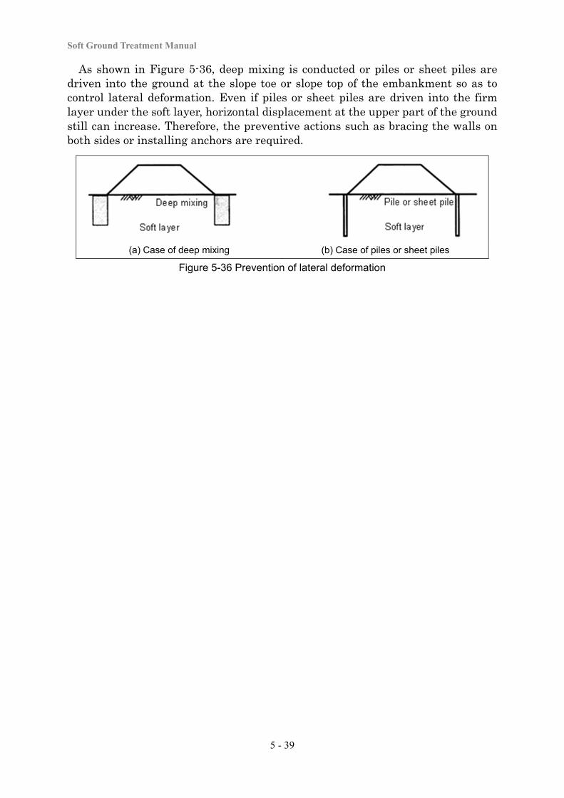
Soft Ground Treatment Manual
5 - 39
As shown in Figure 5-36, deep mixing is conducted or piles or sheet piles are driven into the ground at the slope toe or slope top of the embankment so as to control lateral deformation. Even if piles or sheet piles are driven into the firm layer under the soft layer, horizontal displacement at the upper part of the ground still can increase. Therefore, the preventive actions such as bracing the walls on both sides or installing anchors are required.
(a) Case of deep mixing (b) Case of piles or sheet piles
Figure 5-36 Prevention of lateral deformation

Chapter 5 Work Control and Maintenance
5 - 40
1) John Dunnicliff (1993) ; Geotechnical instrumentation for monitoring field performance, Jon Wiley & Sons, inc.
2) (RST Instruments Ltd. http://www.rstinstruments.com/Settlement%20Plate.htm)
3) (STS Corporation Japan http://www.sts-s.co.jp/STS_e/lineup/neil_plate/neil_plate.html#_pile )