Chapter 4 Lab A – Configuring CBAC and Zone-Based...
50
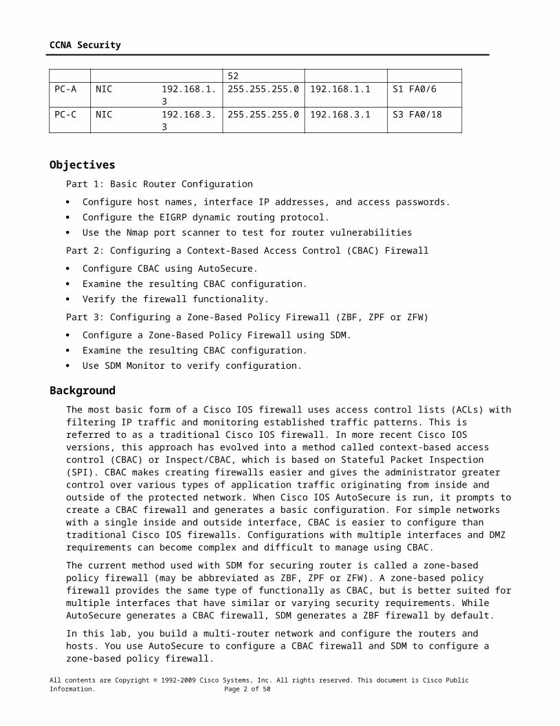
CCNA Security Chapter 4 Lab A, Configuring CBAC and Zone-Based Firewalls Instructor Version Topology IP Addressing Table Devic e Interface IP Address Subnet Mask Default Gateway Switch Port R1 FA0/1 192.168.1. 1 255.255.255.0 N/A S1 FA0/5 S0/0/0 (DCE) 10.1.1.1 255.255.255.2 52 N/A N/A R2 S0/0/0 10.1.1.2 255.255.255.2 52 N/A N/A S0/0/1 (DCE) 10.2.2.2 255.255.255.2 52 N/A N/A R3 FA0/1 192.168.3. 1 255.255.255.0 N/A S3 FA0/5 S0/0/1 10.2.2.1 255.255.255.2 N/A N/A All contents are Copyright © 1992–2009 Cisco Systems, Inc. All rights reserved. This document is Cisco Public Information. Page 1 of 50
Transcript of Chapter 4 Lab A – Configuring CBAC and Zone-Based...

CCNA Security
Chapter 4 Lab A, Configuring CBAC and Zone-Based Firewalls Instructor Version
Topology
IP Addressing Table
Device Interface IP Address Subnet Mask Default Gateway Switch PortR1 FA0/1 192.168.1.1 255.255.255.0 N/A S1 FA0/5
S0/0/0 (DCE) 10.1.1.1 255.255.255.252 N/A N/AR2 S0/0/0 10.1.1.2 255.255.255.252 N/A N/A
S0/0/1 (DCE) 10.2.2.2 255.255.255.252 N/A N/AR3 FA0/1 192.168.3.1 255.255.255.0 N/A S3 FA0/5
S0/0/1 10.2.2.1 255.255.255.252 N/A N/APC-A NIC 192.168.1.3 255.255.255.0 192.168.1.1 S1 FA0/6PC-C NIC 192.168.3.3 255.255.255.0 192.168.3.1 S3 FA0/18
ObjectivesPart 1: Basic Router Configuration
All contents are Copyright © 1992–2009 Cisco Systems, Inc. All rights reserved. This document is Cisco Public Information. Page 1 of 42
CCNA Security
Configure host names, interface IP addresses, and access passwords. Configure the EIGRP dynamic routing protocol. Use the Nmap port scanner to test for router vulnerabilities
Part 2: Configuring a Context-Based Access Control (CBAC) Firewall
Configure CBAC using AutoSecure. Examine the resulting CBAC configuration. Verify the firewall functionality.
Part 3: Configuring a Zone-Based Policy Firewall (ZBF, ZPF or ZFW)
Configure a Zone-Based Policy Firewall using SDM. Examine the resulting CBAC configuration. Use SDM Monitor to verify configuration.
BackgroundThe most basic form of a Cisco IOS firewall uses access control lists (ACLs) with filtering IP traffic and monitoring established traffic patterns. This is referred to as a traditional Cisco IOS firewall. In more recent Cisco IOS versions, this approach has evolved into a method called context-based access control (CBAC) or Inspect/CBAC, which is based on Stateful Packet Inspection (SPI). CBAC makes creating firewalls easier and gives the administrator greater control over various types of application traffic originating from inside and outside of the protected network. When Cisco IOS AutoSecure is run, it prompts to create a CBAC firewall and generates a basic configuration. For simple networks with a single inside and outside interface, CBAC is easier to configure than traditional Cisco IOS firewalls. Configurations with multiple interfaces and DMZ requirements can become complex and difficult to manage using CBAC.
The current method used with SDM for securing router is called a zone-based policy firewall (may be abbreviated as ZBF, ZPF or ZFW). A zone-based policy firewall provides the same type of functionally as CBAC, but is better suited for multiple interfaces that have similar or varying security requirements. While AutoSecure generates a CBAC firewall, SDM generates a ZBF firewall by default.
In this lab, you build a multi-router network and configure the routers and hosts. You use AutoSecure to configure a CBAC firewall and SDM to configure a zone-based policy firewall.
Note: The router commands and output in this lab are from a Cisco 1841 with Cisco IOS Release 12.4(20)T (Advanced IP image). Other routers and Cisco IOS versions can be used. See the Router Interface Summary table at the end of the lab to determine which interface identifiers to use based on the equipment in the lab. Depending on the router model and Cisco IOS version, the commands available and output produced might vary from what is shown in this lab.
Note: Make sure that the routers and the switches have been erased and have no startup configurations.
Instructor Note: Instructions for erasing switches and routers are provided in the Lab Manual, located on Academy Connection in the Tools section.
Required Resources 3 routers with SDM 2.5 installed (Cisco 1841 with Cisco IOS Release 12.4(20)T1 or comparable)
2 switches (Cisco 2960 or comparable)
PC-A (Windows XP or Vista)
PC-C (Windows XP or Vista)
Serial and Ethernet cables as shown in the topology
Rollover cables to configure the routers via the console
All contents are Copyright © 1992–2009 Cisco Systems, Inc. All rights reserved. This document is Cisco Public Information. Page 2 of 42

CCNA Security
Instructor Notes:This lab is divided into three parts. Each part can be administered individually or in combination with others as time permits. The main goal is to configure a firewall on one router using AutoSecure and CBAC, and configure a firewall on another router using SDM and ZBF.
R1 and R3 are on separate networks and communicate through R2, which simulates an ISP. The routers in this lab are configured with EIGRP, although it is not typical for stub networks to communicate with an ISP using an interior routing protocol. EIGRP is used to demonstrate how SDM can detect the use of the routing protocol and give the option of configuring the ZBF firewall to allow dynamic updates to be sent and received.
Students can work in teams of two for router configuration, one person configuring R1 and the other R3.
Although switches are shown in the topology, students can omit the switches and use crossover cables between the PCs and routers R1 and R3.
The basic running configs for all three routers are captured after Part 1 of the lab is completed. The running config commands that are added to R1 in Part 2 and to R3 in Part 3 are captured and listed separately. All configs are found at the end of the lab.
Part 1: Basic Router ConfigurationIn Part 1 of this lab, you set up the network topology and configure basic settings, such as the interface IP addresses, dynamic routing, device access, and passwords.
Note: All tasks should be performed on routers R1, R2 and R3. The procedure for R1 is shown here as an example.
Task 1: Configure Basic Router Settings
Step 1: Cable the network as shown in the topology.Attach the devices shown in the topology diagram, and cable as necessary.
Step 2: Configure basic settings for each router.a. Configure host names as shown in the topology.
b. Configure the interface IP addresses as shown in the IP addressing table.
c. Configure a clock rate for the serial router interfaces with a DCE serial cable attached.
R1(config)#interface S0/0/0R1(config-if)#clock rate 64000
Step 3. Disable DNS lookup.To prevent the router from attempting to translate incorrectly entered commands, disable DNS lookup.
R1(config)#no ip domain-lookup
Step 4: Configure the EIGRP routing protocol on R1, R2, and R3.a. On R1, use the following commands.
R1(config)#router eigrp 101R1(config-router)#network 192.168.1.0 0.0.0.255R1(config-router)#network 10.1.1.0 0.0.0.3R1(config-router)#no auto-summary
All contents are Copyright © 1992–2009 Cisco Systems, Inc. All rights reserved. This document is Cisco Public Information. Page 3 of 42

CCNA Security
b. On R2, use the following commands.
R2(config)#router eigrp 101R2(config-router)#network 10.1.1.0 0.0.0.3R2(config-router)#network 10.2.2.0 0.0.0.3R2(config-router)#no auto-summary
c. On R3, use the following commands.
R3(config)#router eigrp 101R3(config-router)#network 192.168.3.0 0.0.0.255R3(config-router)#network 10.2.2.0 0.0.0.3R3(config-router)#no auto-summary
Step 5: Configure PC host IP settings.a. Configure a static IP address, subnet mask, and default gateway for PC-A, as shown in the IP
addressing table.
b. Configure a static IP address, subnet mask, and default gateway for PC-C, as shown in the IP addressing table.
Step 6: Verify basic network connectivity.a. Ping from R1 to R3.
Were the results successful? Yes.
If the pings are not successful, troubleshoot the basic device configurations before continuing.
b. Ping from PC-A on the R1 LAN to PC-C on the R3 LAN.
Were the results successful? Yes.
If the pings are not successful, troubleshoot the basic device configurations before continuing.
Note: If you can ping from PC-A to PC-C, you have demonstrated that the EIGRP routing protocol is configured and functioning correctly. If you cannot ping but the device interfaces are up and IP addresses are correct, use the show run and show ip route commands to help identify routing protocol-related problems.
Step 7: Configure a minimum password length.Note: Passwords in this lab are set to a minimum of 10 characters but are relatively simple for the benefit of performing the lab. More complex passwords are recommended in a production network.
Use the security passwords command to set a minimum password length of 10 characters.
R1(config)# security passwords min-length 10
Step 8: Configure basic console, auxiliary port, and vty lines.a. Configure a console password and enable login for router R1. For additional security, the exec-
timeout command causes the line to log out after 5 minutes of inactivity. The logging synchronous command prevents console messages from interrupting command entry.
Note: To avoid repetitive logins during this lab, the exec-timeout can be set to 0 0, which prevents it from expiring. However, this is not considered a good security practice.
R1(config)#line console 0R1(config-line)#password ciscoconpassR1(config-line)#exec-timeout 5 0R1(config-line)#loginR1(config-line)#logging synchronous
All contents are Copyright © 1992–2009 Cisco Systems, Inc. All rights reserved. This document is Cisco Public Information. Page 4 of 42

CCNA Security
b. Configure a password for the aux port for router R1.
R1(config)#line aux 0R1(config-line)#password ciscoauxpassR1(config-line)#exec-timeout 5 0R1(config-line)#login
c. Configure the password on the vty lines for router R1.
R1(config)#line vty 0 4R1(config-line)#password ciscovtypassR1(config-line)#exec-timeout 5 0R1(config-line)#login
d. Repeat these configurations on both R2 and R3.
Step 8: Enable HTTP server and HTTP server secure.Enabling these services allows the router to be managed using the GUI and a web browser.
R1(config)#ip http server
Step 9: Encrypt clear text passwords.a. Use the service password-encryption command to encrypt the console, aux, and vty
passwords.
R1(config)# service password-encryption
b. Issue the show run command. Can you read the console, aux, and vty passwords? Why or why not?
No, the passwords are now encrypted
c. Repeat this configuration on both R2 and R3.
Step 10: Save the basic running configuration for all three routers.Save the running configuration to the startup configuration from the privileged EXEC prompt.
R1#copy running-config startup-config
Task 2: Use the Nmap Port Scanner to Determine Router VulnerabilitiesIn this task you determine open ports or services running on R1 using Nmap, before configuring a firewall.
Step 1: (Optional) Download and install Nmap and the Zenmap GUI front-end.Nmap ("Network Mapper") is a free and open source utility for network exploration or security auditing.
a. If Nmap is already installed on PC-A and PC-C, go to Step 2. Otherwise, download the latest Windows version from http://nmap.org/download.html.
b. On PC-A and PC-C, run the Nmap setup utility and install all components listed, including the Zenmap GUI front-end. Click Next to accept the defaults when prompted.
All contents are Copyright © 1992–2009 Cisco Systems, Inc. All rights reserved. This document is Cisco Public Information. Page 5 of 42

CCNA Security
Step 2: Scan for open ports on R1 using Nmap from internal host PC-A.a. From internal host PC-A, start the Nmap-Zenmap application and enter the IP address of the default
gateway, R1 Fa0/1 (192.168.1.1), as the Target. Accept the default Nmap command entered for you in the Command window and use the Intense scan profile.
Note: If the PC is running a personal firewall it may be necessary to turn it off temporarily to obtain accurate test results.
b. Click the Scan button to begin the scan of R1 from internal host PC-A. Allow some time for the scan to complete. The next two screens show the entire output of the scan after scrolling.
All contents are Copyright © 1992–2009 Cisco Systems, Inc. All rights reserved. This document is Cisco Public Information. Page 6 of 42

CCNA Security
All contents are Copyright © 1992–2009 Cisco Systems, Inc. All rights reserved. This document is Cisco Public Information. Page 7 of 42

CCNA Security
c. Click the Service button in the upper left side of the screen. What ports are open on R1 Fa0/1 from the perspective of internal host PC-A? From internal PC-A Nmap detects open ports 23 (Telnet) and 80 (HTTP).
What is the MAC address of the R1 Fa0/1 interface? Answers will vary. For this router it is 00:1B:53:25:25:6F.
For R1, what type of device and what OS version does Nmap detect? Answers may vary but Nmap determines that R1 is a router and that it is running Cisco IOS version 12.4.
Step 3: Scan for open ports on R1 using Nmap from external host PC-C.a. From external host PC-C, start the Nmap-Zenmap application and enter the IP address of R1 S0/0/0
(10.1.1.1) as the Target. Accept the default Nmap command entered for you in the Command window and use the Intense scan profile.
All contents are Copyright © 1992–2009 Cisco Systems, Inc. All rights reserved. This document is Cisco Public Information. Page 8 of 42

CCNA Security
b. Click the Scan button. Allow some time for the scan to complete. The next two screens show the entire output of the scan after scrolling.
All contents are Copyright © 1992–2009 Cisco Systems, Inc. All rights reserved. This document is Cisco Public Information. Page 9 of 42

CCNA Security
c. Click the Services button below the Command entry field. What services are running and available on R1 from the perspective of PC-C? Telnet and HTTP
d. In the Nmap scan output, refer to the TRACEROUTE information. How many hops are between PC-C and R1 and through what IP addresses did the scan have to go to reach R1? Three hops. The scan went from PC-C to the R3 Fa0/1 default gateway (192.168.3.1) to R2 S0/0/1 (10.2.2.2) and then to R1 S0/0/0 (10.1.1.1).
Note: In Part 2 of this lab you will configure a CBAC firewall on R1 and then run Nmap again to test access from external host PC-C to R1.
All contents are Copyright © 1992–2009 Cisco Systems, Inc. All rights reserved. This document is Cisco Public Information. Page 10 of 42

CCNA Security
Part 2: Configuring a Context-Based Access Control (CBAC) FirewallIn Part 2 of this lab, you configure CBAC on R1 using AutoSecure. You then review and test the resulting configuration.
Task 1: Verify Access to the R1 LAN from R2In this task, you verify that with no firewall in place, the external router R2 can ping the R1 S0/0/0 interface and PC-A on the R1 internal LAN.
Step 1: Ping from R2 to R1.a. From R2, ping the R1 interface S0/0/0 at IP address 10.1.1.1.
R2#ping 10.1.1.1
b. Were the results successful? Yes.
If the pings are not successful, troubleshoot the basic device configurations before continuing.
Step 2: Ping from R2 to PC-A on the R1 LAN.a. From R2, ping PC-A on the R1 LAN at IP address 192.168.1.3.
R2#ping 192.168.1.3
b. Were the results successful? Yes.
If the pings are not successful, troubleshoot the basic device configurations before continuing.
Step 3: Display the R1 running config prior to using AutoSecure.a. Issue the show run command to review the current basic configuration on R1.
b. Are there any security commands related to access control? No, there is a minimum password length of 10. Login passwords and exec-timeout are defined on the console, vty, and aux lines.
Task 2: Use AutoSecure to Secure R1 and Enable CBACAutoSecure simplifies the security configuration of a router and hardens the router configuration. In this task, you run AutoSecure and enable CBAC during the process.
Step 1: Use the AutoSecure IOS feature to enable CBAC.a. Enter privileged EXEC mode using the enable command.
b. Issue the auto secure command on R1. Respond as shown in the following AutoSecure output to the AutoSecure questions and prompts. The responses are bolded.
Note: The focus here is the commands generated by AutoSecure for CBAC, so you do not enable all the potential security features that AutoSecure can provide, such as SSH access. Be sure to respond “yes” to the prompt Configure CBAC Firewall feature?.R1#auto secure --- AutoSecure Configuration ---
*** AutoSecure configuration enhances the security of the router, but it will not make it absolutely resistant to all security attacks ***
AutoSecure will modify the configuration of your device. All configuration changes will be shown. For a detailed explanation of how the configuration
All contents are Copyright © 1992–2009 Cisco Systems, Inc. All rights reserved. This document is Cisco Public Information. Page 11 of 42

CCNA Security
changes enhance security and any possible side effects, please refer to Cisco.com forAutosecure documentation.At any prompt you may enter '?' for help.Use ctrl-c to abort this session at any prompt.
Gathering information about the router for AutoSecure
Is this router connected to internet? [no]: yesEnter the number of interfaces facing the internet [1]: 1
Interface IP-Address OK? Method Status ProtocolFastEthernet0/0 unassigned YES unset administratively down down
FastEthernet0/1 192.168.1.1 YES manual up up
Serial0/0/0 10.1.1.1 YES SLARP up up
Serial0/0/1 unassigned YES unset administratively down down
Enter the interface name that is facing the internet: serial0/0/0
Securing Management plane services...
Disabling service fingerDisabling service padDisabling udp & tcp small serversEnabling service password encryptionEnabling service tcp-keepalives-inEnabling service tcp-keepalives-outDisabling the cdp protocol
Disabling the bootp serverDisabling the http serverDisabling the finger serviceDisabling source routingDisabling gratuitous arp
Here is a sample Security Banner to be shownat every access to device. Modify it to suit yourenterprise requirements.
Authorized Access only This system is the property of So-&-So-Enterprise. UNAUTHORIZED ACCESS TO THIS DEVICE IS PROHIBITED. You must have explicit permission to access this device. All activities performed on this device are logged. Any violations of access policy will result in disciplinary action.
Enter the security banner {Put the banner betweenk and k, where k is any character}:
$ Unauthorized Access Prohibited $
Enable secret is either not configured or is the same as enable password
All contents are Copyright © 1992–2009 Cisco Systems, Inc. All rights reserved. This document is Cisco Public Information. Page 12 of 42

CCNA Security
Enter the new enable secret: cisco12345Confirm the enable secret : cisco12345Enter the new enable password: cisco67890Confirm the enable password: cisco67890
Configuration of local user databaseEnter the username: adminEnter the password: cisco12345Confirm the password: cisco12345Configuring AAA local authenticationConfiguring Console, Aux and VTY lines forlocal authentication, exec-timeout, and transportSecuring device against Login AttacksConfigure the following parameters
Blocking Period when Login Attack detected: 60
Maximum Login failures with the device: 2
Maximum time period for crossing the failed login attempts: 30
Configure SSH server? [yes]: no
Configuring interface specific AutoSecure servicesDisabling the following ip services on all interfaces:
no ip redirects no ip proxy-arp no ip unreachables no ip directed-broadcast no ip mask-replyDisabling mop on Ethernet interfaces
Securing Forwarding plane services...
Enabling CEF (This might impact the memory requirements for your platform)Enabling unicast rpf on all interfaces connectedto internet
Configure CBAC Firewall feature? [yes/no]: yes
This is the configuration generated:
no service fingerno service padno service udp-small-serversno service tcp-small-serversservice password-encryptionservice tcp-keepalives-inservice tcp-keepalives-outno cdp runno ip bootp serverno ip http serverno ip fingerno ip source-routeno ip gratuitous-arpsno ip identd
All contents are Copyright © 1992–2009 Cisco Systems, Inc. All rights reserved. This document is Cisco Public Information. Page 13 of 42

CCNA Security
banner motd ^C Unauthorized Access Prohibited ^Csecurity authentication failure rate 10 logenable secret 5 $1$m.de$Mp5tQr/I8W5VhuQoG6AoA1enable password 7 05080F1C2243185E415C47username admin password 7 02050D4808095E731F1A5Caaa new-modelaaa authentication login local_auth localline con 0 login authentication local_auth exec-timeout 5 0 transport output telnetline aux 0 login authentication local_auth exec-timeout 10 0 transport output telnetline vty 0 4 login authentication local_auth transport input telnetline tty 1 login authentication local_auth exec-timeout 15 0login block-for 60 attempts 2 within 30service timestamps debug datetime msec localtime show-timezoneservice timestamps log datetime msec localtime show-timezonelogging facility local2logging trap debuggingservice sequence-numberslogging console criticallogging bufferedinterface FastEthernet0/0 no ip redirects no ip proxy-arp no ip unreachables no ip directed-broadcast no ip mask-reply no mop enabledinterface FastEthernet0/1 no ip redirects no ip proxy-arp no ip unreachables no ip directed-broadcast no ip mask-reply no mop enabledinterface Serial0/0/0 no ip redirects no ip proxy-arp no ip unreachables no ip directed-broadcast no ip mask-replyinterface Serial0/0/1 no ip redirects no ip proxy-arp no ip unreachables no ip directed-broadcast no ip mask-replyinterface Vlan1 no ip redirects no ip proxy-arp
All contents are Copyright © 1992–2009 Cisco Systems, Inc. All rights reserved. This document is Cisco Public Information. Page 14 of 42

CCNA Security
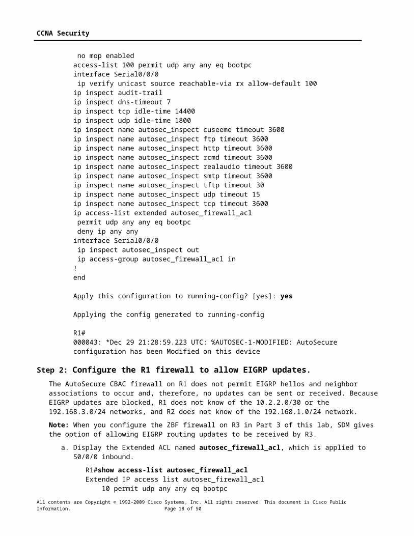
no ip unreachables no ip directed-broadcast no ip mask-reply no mop enabledaccess-list 100 permit udp any any eq bootpcinterface Serial0/0/0 ip verify unicast source reachable-via rx allow-default 100ip inspect audit-trailip inspect dns-timeout 7ip inspect tcp idle-time 14400ip inspect udp idle-time 1800ip inspect name autosec_inspect cuseeme timeout 3600ip inspect name autosec_inspect ftp timeout 3600ip inspect name autosec_inspect http timeout 3600ip inspect name autosec_inspect rcmd timeout 3600ip inspect name autosec_inspect realaudio timeout 3600ip inspect name autosec_inspect smtp timeout 3600ip inspect name autosec_inspect tftp timeout 30ip inspect name autosec_inspect udp timeout 15ip inspect name autosec_inspect tcp timeout 3600ip access-list extended autosec_firewall_acl permit udp any any eq bootpc deny ip any anyinterface Serial0/0/0 ip inspect autosec_inspect out ip access-group autosec_firewall_acl in!end
Apply this configuration to running-config? [yes]: yes
Applying the config generated to running-config
R1#000043: *Dec 29 21:28:59.223 UTC: %AUTOSEC-1-MODIFIED: AutoSecure configuration has been Modified on this device
Step 2: Configure the R1 firewall to allow EIGRP updates.The AutoSecure CBAC firewall on R1 does not permit EIGRP hellos and neighbor associations to occur and, therefore, no updates can be sent or received. Because EIGRP updates are blocked, R1 does not know of the 10.2.2.0/30 or the 192.168.3.0/24 networks, and R2 does not know of the 192.168.1.0/24 network.
Note: When you configure the ZBF firewall on R3 in Part 3 of this lab, SDM gives the option of allowing EIGRP routing updates to be received by R3.
a. Display the Extended ACL named autosec_firewall_acl, which is applied to S0/0/0 inbound.
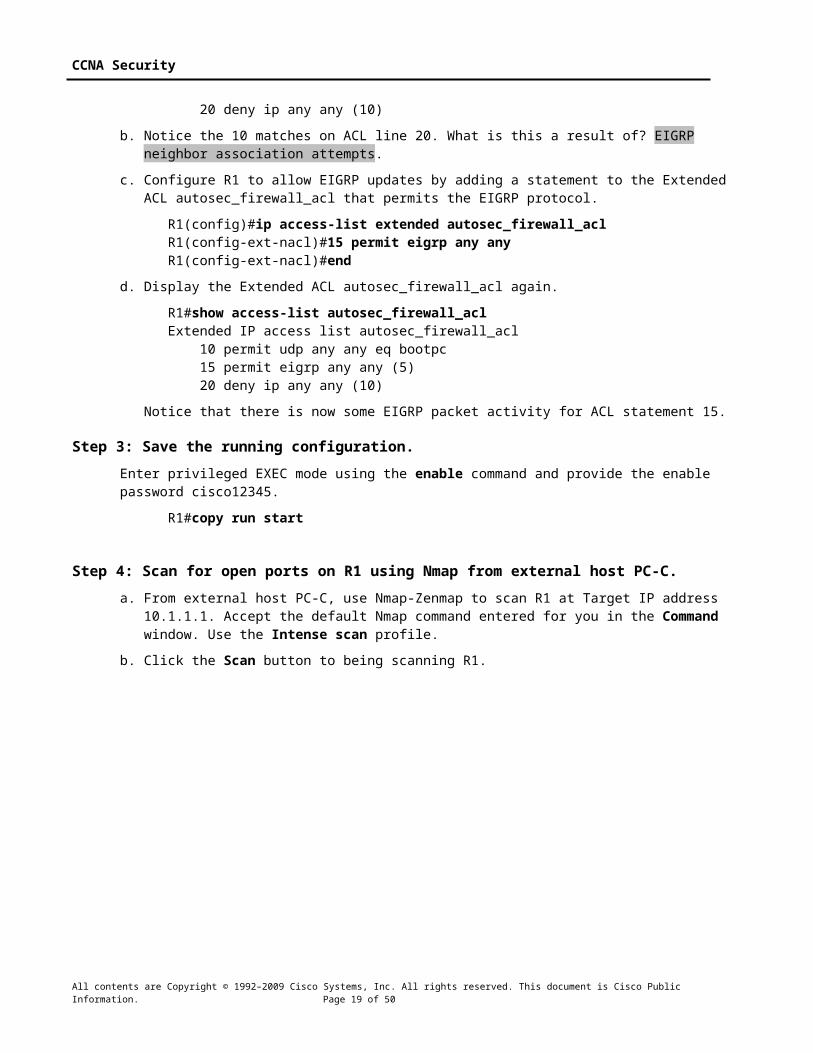
R1#show access-list autosec_firewall_aclExtended IP access list autosec_firewall_acl 10 permit udp any any eq bootpc 20 deny ip any any (10)
b. Notice the 10 matches on ACL line 20. What is this a result of? EIGRP neighbor association attempts.
c. Configure R1 to allow EIGRP updates by adding a statement to the Extended ACL autosec_firewall_acl that permits the EIGRP protocol.
R1(config)#ip access-list extended autosec_firewall_aclR1(config-ext-nacl)#15 permit eigrp any anyR1(config-ext-nacl)#end
All contents are Copyright © 1992–2009 Cisco Systems, Inc. All rights reserved. This document is Cisco Public Information. Page 15 of 42

CCNA Security
d. Display the Extended ACL autosec_firewall_acl again.
R1#show access-list autosec_firewall_aclExtended IP access list autosec_firewall_acl 10 permit udp any any eq bootpc 15 permit eigrp any any (5) 20 deny ip any any (10)
Notice that there is now some EIGRP packet activity for ACL statement 15.
Step 3: Save the running configuration.Enter privileged EXEC mode using the enable command and provide the enable password cisco12345.
R1#copy run start
Step 4: Scan for open ports on R1 using Nmap from external host PC-C.a. From external host PC-C, use Nmap-Zenmap to scan R1 at Target IP address 10.1.1.1. Accept the
default Nmap command entered for you in the Command window. Use the Intense scan profile.
b. Click the Scan button to being scanning R1.
Now that the R1 CBAC firewall is in place, what services are available on R1 and what is the status of R1 from the perspective of external PC-C? No services are detected. Nmap, run from PC-C, reports the status of host R1 10.1.1.1 as down.
All contents are Copyright © 1992–2009 Cisco Systems, Inc. All rights reserved. This document is Cisco Public Information. Page 16 of 42

CCNA Security
Task 3: Review the AutoSecure CBAC Configuration
Step 1: Review the commands that were delivered to router R1.a. Display the running configuration for R1. The AutoSecure output should look similar to that shown in
Task 2, Step 1.
b. What is the most common command issued that is related to CBAC? ip inspect name autosec_inspect
c. CBAC creates rules to track TCP and UDP flows using the ip inspect name name protocol command. To what interface is the autosec_inspect name applied and in what direction? Serial0/0/0 interface in the outbound direction.
Step 2: Display the protocols available with the ip inspect command.a. To see the protocols available, enter the ip inspect name name command in global config mode,
followed by a question mark (?).
Note: Most of the protocols listed are application layer protocols. Newer Cisco IOS versions have more protocols listed.
R1(config)# ip inspect name autosec_inspect ? 802-11-iapp IEEE 802.11 WLANs WG IAPP ace-svr ACE Server/Propagation appfw Application Firewall appleqtc Apple QuickTime bgp Border Gateway Protocolbiff Bliff mail notificationbittorrent bittorrent<Output Omitted>
b. How many protocols can be configured for inspection? Over one hundred
c. Refer to the running configuration output or the AutoSecure output in Task 2, Step 1. Which protocols did AutoSecure configure to be inspected as they leave the S0/0/0 interface? Cuseeme, FTP, HTTP, RCMD, Realaudio, SMTP, TFTP, UDP AND TCP.
d. To which interface is the ACL autosec_firewall_acl applied and in which direction? S0/0/0 inbound.
e. What is the purpose of the ACL autosec_firewall_acl? It allows bootp traffic to enter the S0/0/0 interface and blocks all other non-established connections from outside R1.
Task 4: Verify CBAC FunctionalityFor the protocols identified to be inspected, the CBAC firewall allows return traffic for connections initiated from the inside, but blocks all other connections from the outside.
Step 1: From PC-A, ping the R1 internal LAN interface.a. From PC-A, ping R1 interface Fa0/1 at IP address 192.168.1.1.
C:\>ping 192.168.1.1
b. Were the pings successful? Why or why not? Yes, PC-A IP address and the R1 Fa0/1 IP address are on the same internal network, and the firewall does not come into play. The R1 Fa0/1 IP address is PC-A’s default gateway.
Step 2: From PC-A, ping the R2 external WAN interface.a. From PC-A, ping the R2 interface S0/0/0 at IP address 10.1.1.2.
All contents are Copyright © 1992–2009 Cisco Systems, Inc. All rights reserved. This document is Cisco Public Information. Page 17 of 42
CCNA Security
C:\>ping 10.1.1.2
b. Were the pings successful? Why or why not? No. The ICMP protocol was not included in the autosec_inspect list, so the pings that PC-A sends are blocked from returning.
Step 3: Add ICMP to the autosec_inspect list.From global config mode, configure R1 to inspect ICMP and allow ICMP echo replies from outside hosts.
R1(config)#ip inspect name autosec_inspect icmp timeout 5
Step 4: From PC-A, ping the R2 external WAN interface.a. From PC-A, ping the R2 interface S0/0/0 at IP address 10.1.1.2.
C:\>ping 10.1.1.2
b. Were the pings successful? Why or why not? Yes, ICMP is now included in the autosec_inspect list, so the ICMP replies for ICMP requests originating from within the R1 LAN are allowed to return.
c. Remove ICMP from the inspect list. This restores the CBAC configuration to the one generated by AutoSecure.
R1(config)#no ip inspect name autosec_inspect icmp timeout 5
Step 5: Test Telnet access from R2 to R1.a. From external router R2, telnet to R1 at IP address 10.1.1.1.
R2>telnet 10.1.1.1Trying 10.1.1.1 ...% Connection timed out; remote host not responding
b. Was the telnetting successful? Why or why not? No, the connection was initiated from outside and was blocked by the firewall ACL.
Step 6: Configure R1 to allow Telnet access from external hosts.a. Display the Extended ACL named autosec_firewall_acl that is applied to S0/0/0 inbound.
R1#show access-list autosec_firewall_aclExtended IP access list autosec_firewall_acl 10 permit udp any any eq bootpc 15 permit eigrp any any (15) 20 deny ip any any (57 matches)
b. Notice the 57 matches on ACL line 20. What is this a result of? Previous ping and telnet attempts that have been denied.
c. Configure R1 to allow Telnet access by adding a statement to the Extended ACL autosec_firewall_acl that permits TCP port 23 (Telnet).
R1(config)#ip access-list extended autosec_firewall_aclR1(config-ext-nacl)#18 permit tcp any any eq 23R1(config-ext-nacl)#end
d. From external router R2, telnet again to R1 at IP address 10.1.1.1.
R2>telnet 10.1.1.1Trying 10.1.1.1 ... Open
Unauthorized Access Prohibited
User Access Verification
All contents are Copyright © 1992–2009 Cisco Systems, Inc. All rights reserved. This document is Cisco Public Information. Page 18 of 42
CCNA Security
Username: adminPassword: cisco12345
R1>
e. From the Telnet session on R1, display the modified Extended ACL autosec_firewall_acl.
R1>show access-list autosec_firewall_aclExtended IP access list autosec_firewall_acl 10 permit udp any any eq bootpc 15 permit eigrp any any (25) 18 permit tcp any any eq telnet (12 matches) 20 deny ip any any (57 matches)
f. Notice the new line 18 in the ACL and the 12 matches. What is this a result of? The telnet attempt that was just permitted.
g. Remove Telnet external access from the R1 firewall ACL.
R1(config)#ip access-list extended autosec_firewall_aclR1(config-ext-nacl)#no 18 permit tcp any any eq telnetR1(config-ext-nacl)#end
Note: SSH is recommended instead of Telnet, because it provides a more secure way to allow remote administration access to a router or other networking device. SSH provides encrypted communication, however, some additional configuration is required to support the SSH connection. Refer to Chapter 2 Lab A for the procedure to enable SSH. For added security, configure SSH as the only input transport on the vty lines and remove Telnet as an input transport. Allowing SSH access to R1 from external hosts also requires adding a statement to the Extended ACL autosec_firewall_acl that permits TCP port 22 (SSH).
Step 7: Test Telnet access from internal PC-A to external router R2.a. From PC-A, telnet to R2 at IP address 10.1.1.2.
C:\>telnet 10.1.1.2
b. Was the telnet attempt successful? Why or why not? Yes, the connection was initiated from within the R1 LAN and was permitted.
c. Log in to R2 by providing the vty password of ciscovtypass.
d. Leave the Telnet session open.
Task 5: Verify CBAC Configuration and Operation
Step 1: Display CBAC inspection information.a. Use the show ip inspect all command to see the configuration and inspection status.
Note: The end of the command output shows the established sessions and the inspected TCP Telnet connection between PC-A and R2.
R1#show ip inspect allSession audit trail is enabledSession alert is enabledone-minute (sampling period) thresholds are [unlimited : unlimited] connectionsmax-incomplete sessions thresholds are [unlimited : unlimited]max-incomplete tcp connections per host is unlimited. Block-time 0 minute.tcp synwait-time is 30 sec -- tcp finwait-time is 5 sectcp idle-time is 14400 sec -- udp idle-time is 1800 sectcp reassembly queue length 16; timeout 5 sec; memory-limit 1024 kilo bytes
All contents are Copyright © 1992–2009 Cisco Systems, Inc. All rights reserved. This document is Cisco Public Information. Page 19 of 42

CCNA Security
dns-timeout is 7 secInspection Rule Configuration Inspection name autosec_inspect cuseeme alert is on audit-trail is on timeout 3600 ftp alert is on audit-trail is on timeout 3600 http alert is on audit-trail is on timeout 3600 rcmd alert is on audit-trail is on timeout 3600 rcmd alert is on audit-trail is on timeout 3600 smtp max-data 20000000 alert is on audit-trail is on timeout 3600 tftp alert is on audit-trail is on timeout 30 udp alert is on audit-trail is on timeout 15 tcp alert is on audit-trail is on timeout 3600
Interface Configuration Interface Serial0/0/0 Inbound inspection rule is not set Outgoing inspection rule is autosec_inspect cuseeme alert is on audit-trail is on timeout 3600 ftp alert is on audit-trail is on timeout 3600 http alert is on audit-trail is on timeout 3600 rcmd alert is on audit-trail is on timeout 3600 realaudio alert is on audit-trail is on timeout 3600 smtp max-data 20000000 alert is on audit-trail is on timeout 3600 tftp alert is on audit-trail is on timeout 30 udp alert is on audit-trail is on timeout 15 tcp alert is on audit-trail is on timeout 3600 Inbound access list is autosec_firewall_acl Outgoing access list is not set
Established Sessions Session 6556C128 (192.168.1.3:1185)=>(10.1.1.2:23) tcp SIS_OPEN
b. In the Established Sessions section, what is the source IP address and port number for Session 655C128? 192.168.1.3 and port 1185. The source port will vary.
c. What is the destination IP address and port number for Session 655C128? 10.1.1.2 and port 23 (telnet).
Step 2: View detailed session information.a. View detailed session information using the show ip inspect sessions detail command on
R1.
R1#show ip inspect sessions detailEstablished Sessions Session 6556C128 (192.168.1.3:1185)=>(10.1.1.2:23) tcp SIS_OPEN Created 00:00:09, Last heard 00:00:02 Bytes sent (initiator:responder) [45:154] In SID 10.1.1.2[23:23]=>192.168.1.3[1185:1185] on ACL autosec_firewall_acl (19 matches)
b. Close the Telnet connection when you are finished verifying CBAC operation.
Part 3: Configuring a Zone-Based Firewall (ZBF) Using SDMIn Part 3 of this lab, you configure a zone-based firewall (ZBF) on R3 using SDM.
All contents are Copyright © 1992–2009 Cisco Systems, Inc. All rights reserved. This document is Cisco Public Information. Page 20 of 42

CCNA Security
Task 1: Verify Access to the R3 LAN from R2In this task, you verify that with no firewall in place, external router R2 can access the R3 S0/0/1 interface and PC-C on the R3 internal LAN.
Step 1: Ping from R2 to R3.a. From R2, ping the R3 interface S0/0/1 at IP address 10.2.2.1.
R2#ping 10.2.2.1
b. Were the results successful? Yes.
If the pings are not successful, troubleshoot the basic device configurations before continuing.
Step 2: Ping from R2 to PC-C on the R3 LAN.a. From R2, ping PC-C on the R3 LAN at IP address 192.168.3.3.
R2#ping 192.168.3.3
b. Were the results successful? Yes.
If the pings are not successful, troubleshoot the basic device configurations before continuing.
Step 3: Display the R3 running config prior to starting SDM.a. Issue the show run command to review the current basic configuration on R3.
b. Verify the R3 basic configuration as performed in Part 1 of the lab. Are there any security commands related to access control? There should not be. There is a minimum password length of 10. Login passwords and exec-timeout are defined on the console, vty, and aux lines.
Task 2: Create a Zone-Based Policy FirewallIn this task, you use Cisco SDM to create a zone-based policy firewall on R3.
Step 1: Configure the enable secret password and HTTP router access prior to starting SDM.a. From the CLI, configure the enable secret password for use with SDM on R3.
R3(config)#enable secret cisco12345
b. Enable the HTTP server on R3.
R3(config)#ip http server
Step 2: Access SDM and set command delivery preferences.a. Run the SDM application or open a browser on PC-C and start SDM by entering the R3 IP address
192.168.3.1 in the address field.
b. Log in with no username and the enable secret password cisco12345.
c. In the Password Needed – Networking dialog box, enter cisco12345 in the Password field and click Yes.
d. Select Edit > Preferences to configure SDM to allow you to preview the commands before sending them to the router. In the User Preferences window, check the Preview commands before delivering to router check box and click OK.
Step 3: Use the SDM Firewall wizard to configure a zone-based firewall.a. On the SDM Home page, refer to the Configuration Overview portion of the screen. What is the state
of the Firewall Policies? Should be Inactive.
All contents are Copyright © 1992–2009 Cisco Systems, Inc. All rights reserved. This document is Cisco Public Information. Page 21 of 42

CCNA Security
b. Click the Configure button at the top of the SDM screen, and then click Firewall and ACL. Read through the overview descriptions for the Basic and Advanced Firewall options. What are some of the key differences? Basic Firewall applies a predefined set of rules to protect the internal network, but does not allow the creation of a DMZ. Advanced Firewall allows predefined or customized rules to protect the internal network and also allows the configuration of DMZ services such as FTP or WWW.
c. Select Basic Firewall and click the Launch the selected task button.
d. In the Basic Firewall Configuration Wizard window, familiarize yourself with what the Basic Firewall does. What does the Basic Firewall do with traffic from outside zones to inside zones? Deny it.
e. Click Next to continue.
f. Check the Inside (trusted) check box for FastEthernet0/1 and the Outside (untrusted) check box for Serial0/0/1. Click Next.
All contents are Copyright © 1992–2009 Cisco Systems, Inc. All rights reserved. This document is Cisco Public Information. Page 22 of 42

CCNA Security
g. Click OK when the warning is displayed telling you that you cannot launch SDM from the S0/0/1 interface after the Firewall wizard completes.
h. Move the slider between High, Medium, and Low security to familiarize yourself with what each provides. What is the main difference between High security and Medium or Low security? High security identifies inbound and outbound IM and peer-to-peer (P2P) traffic and drops it. This prevents these applications from being used on the network. Medium security identifies inbound and outbound IM and P2P for tracking, but does not drop it. Low security does not identify application-specific traffic, but it does inspect it to verify that it was initiated from within the internal network.
i. Move the slider to Low Security and click the Preview Commands button to preview the commands that are delivered to the router. When you are finished reviewing the commands, click Close and then click Next.
j. Review the Firewall Configuration Summary. What does this display provide? A textual description (no commands) of what the Firewall wizard does based on the selections that you made.
k. Click Finish to complete the Firewall wizard.
l. When the Routing traffic configuration window displays, ensure that the check box Allow EIGRP updates to come through the firewall is checked and click OK.
Note: This screen only displays if a dynamic routing protocol is configured.
m. What would happen if this box was not checked? EIGRP routing updates from R2 would be blocked at the firewall, and R3 would not learn about the 10.1.1.0/30 or 192.168.1.0/24 networks.
n. In addition to EIGRP, for what other routing protocols does the firewall allow updates? RIP and OSPF.
o. In the Deliver Configuration to Router window, make sure that the Save running config to router’s startup config check box is checked and click Deliver.
p. Click OK in the Commands Delivery Status window. How many commands were generated by the Firewall wizard? 115 commands with SDM 2.5.
q. Click OK to display the message that you have successfully configured a firewall on the router. Click OK to close the message window.
r. The Edit Firewall Policy window displays with the Rule Diagram.
All contents are Copyright © 1992–2009 Cisco Systems, Inc. All rights reserved. This document is Cisco Public Information. Page 23 of 42

CCNA Security
s. In the Rule Diagram, locate access list 100 (folder icon). What action is taken and what rule options are applied for traffic with an invalid source address in the 127.0.0.0/8 address range? Traffic is dropped and logged.
Task 3: Review the Zone-Based Firewall Configuration
Step 1: Examine the R3 running configuration with the CLI.a. From the R3 CLI, display the running configuration to view the changes that the SDM Basic Firewall
wizard made to the router.
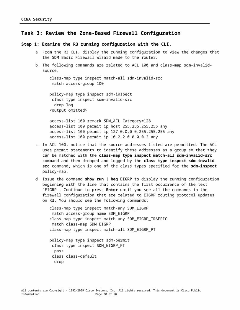
b. The following commands are related to ACL 100 and class-map sdm-invalid-source.
class-map type inspect match-all sdm-invalid-src match access-group 100
policy-map type inspect sdm-inspect class type inspect sdm-invalid-src drop log<output omitted>
access-list 100 remark SDM_ACL Category=128
All contents are Copyright © 1992–2009 Cisco Systems, Inc. All rights reserved. This document is Cisco Public Information. Page 24 of 42

CCNA Security
access-list 100 permit ip host 255.255.255.255 anyaccess-list 100 permit ip 127.0.0.0 0.255.255.255 anyaccess-list 100 permit ip 10.2.2.0 0.0.0.3 any
c. In ACL 100, notice that the source addresses listed are permitted. The ACL uses permit statements to identify these addresses as a group so that they can be matched with the class-map type inspect match-all sdm-invalid-src command and then dropped and logged by the class type inspect sdm-invalid-src command, which is one of the class types specified for the sdm-inspect policy-map.
d. Issue the command show run | beg EIGRP to display the running configuration beginning with the line that contains the first occurrence of the text “EIGRP”. Continue to press Enter until you see all the commands in the firewall configuration that are related to EIGRP routing protocol updates on R3. You should see the following commands:
class-map type inspect match-any SDM_EIGRP match access-group name SDM_EIGRPclass-map type inspect match-any SDM_EIGRP_TRAFFIC match class-map SDM_EIGRPclass-map type inspect match-all SDM_EIGRP_PT
policy-map type inspect sdm-permit class type inspect SDM_EIGRP_PT pass class class-default drop
Step 2: Examine the R3 firewall configuration using SDM.a. Return to the SDM Home page. Refer to the Configuration Overview portion of the screen. What is
the state of Firewall Policies? Should be Active.
b. Click the double down arrow on the right of the Firewall Policies section. What is displayed? Zone pair information.
c. Click the Configure button and select Additional Tasks > ACL Editor > Firewall Rules. There should be an ACL that lists fake source addresses, such as the broadcast address of 255.255.255.255 and the 127.0.0.0/8 network. These were identified in the running configuration output in Task 3, Step 1b.
d. Click the Configure button and select Additional Tasks > Zones to verify the zones configuration. What interfaces are listed and in what zone is each? Interface Serial0/0/1 is in zone out-zone, and interface FastEthernet0/1 is in zone in-zone.
e. Click Configure and select Additional Tasks > Zones Pairs to verify the zone pairs configuration. Fill in the following information.
Zone Pair Source Destination Policy
Sdm-zp-self-out self out-zone sdm-permit-icmpreply
Sdm-zp-out-self out-zone self sdm-permit
Sdm-zp-self-out in-zone out-zone sdm-inspect
f. Click Configure and select Additional Tasks > C3PL.
g. What is C3PL short for? Cisco Common Classification Policy Language.
h. Expand the C3PL menu and select Class Map > Inspection. How many class maps were created by the SDM Firewall wizard? 10
All contents are Copyright © 1992–2009 Cisco Systems, Inc. All rights reserved. This document is Cisco Public Information. Page 25 of 42

CCNA Security
i. Select C3PL > Policy Map > Protocol Inspection. How many policy maps were created by the SDM Firewall wizard? 3
j. Examine the details for the policy map sdm-permit that is applied to the sdm-zp-out-self zone pair. Fill in the information below. List the action for the traffic matching each of the class maps referenced within the sdm-permit policy map.
Match Class Name: SDM_EIGRP_PT Action: PassMatch Class Name: class-default Action: Drop
Task 4: Verify EIGRP Routing Functionality on R3
Step 1: Display the R3 routing table using the CLI. a. In Task 2, Step 3, the Firewall wizard configured the router to allow EIGRP updates. Verify that
EIGRP messages are still being exchanged using the show ip route command and verify that there are still EIGRP learned routes in the routing table.
R3#show ip routeCodes: C - connected, S - static, R - RIP, M - mobile, B - BGP D - EIGRP, EX - EIGRP external, O - OSPF, IA - OSPF inter area<Output omitted>
Gateway of last resort is not set
10.0.0.0/30 is subnetted, 2 subnetsC 10.2.2.0 is directly connected, Serial0/0/1D 10.1.1.0 [90/21024000] via 10.2.2.2, 00:34:12, Serial0/0/1D 192.168.1.0/24 [90/21026560] via 10.2.2.2, 00:32:16, Serial0/0/1C 192.168.3.0/24 is directly connected, FastEthernet0/1
b. Which networks has R3 learned via the EIGRP routing protocol? 10.1.1.0/30 and 192.168.1.0/24
Task 5: Verify Zone-Based Firewall Functionality
Step 1: From PC-C, ping the R3 internal LAN interface.a. From PC-C, ping the R3 interface Fa0/1 at IP address 192.168.3.1.
C:\>ping 192.168.3.1
b. Were the pings successful? Why or why not? Yes, the PC-C IP address and the R3 Fa0/1 IP address are on the same internal network, and the firewall does not come into play. The R3 Fa0/1 IP address is PC-C’s default gateway.
Step 2: From PC-C, ping the R2 external WAN interface.a. From PC-C, ping the R2 interface S0/0/1 at IP address 10.2.2.2.
C:\>ping 10.2.2.2
b. Were the pings successful? Why or why not? Yes, ICMP echo replies are allowed by the sdm-permit-icmpreply policy.
Step 3: From R2 ping PC-C.a. From external router R2, ping PC-C at IP address 192.168.3.3.
R2#ping 192.168.3.3
b. Were the pings successful? Why or why not? No, the ping was initiated from outside R2 S0/0/1 and was blocked.
All contents are Copyright © 1992–2009 Cisco Systems, Inc. All rights reserved. This document is Cisco Public Information. Page 26 of 42

CCNA Security
Step 4: Telnet from R2 to R3.a. From router R2, telnet to R3 at IP address 10.2.2.1.
R2#telnet 10.2.2.1Trying 10.2.2.1 ... Open
Trying 10.2.2.1 ...% Connection timed out; remote host not responding
b. Why was telnetting unsuccessful? The Telnet was initiated from outside R2 S0/0/1 and was blocked.
Step 5: Telnet from internal PC-C to external router R2.a. From PC-C on the R3 internal LAN, telnet to R2 at IP address 10.2.2.2 and log in.
C:\>telnet 10.2.2.2
User Access verificationPassword: ciscovtypass
b. With the Telnet session open from PC-C to R2, enter privileged EXEC mode with the enable command and password cisco12345.
c. Issue the command show policy-map type inspect zone-pair session on R3. Continue pressing enter until you see an Inspect Established session section toward the end. Your output should look similar to the following.
Inspect
Number of Established Sessions = 1 Established Sessions Session 657344C0 (192.168.3.3:1274)=>(10.2.2.2:23) tacacs:tcp SIS_OPEN Created 00:01:20, Last heard 00:01:13 Bytes sent (initiator:responder) [45:65]
d. In the Established Sessions in the output, what is the source IP address and port number for Session 657344C0? 192.168.3.3 and port 1247. The port number may vary.
e. What is the destination IP address and port number for Session 657344C0? 10.2.2.2 and port 23 (telnet).
Step 6: Verify the ZBF function using SDM Monitor.a. From SDM, click the Monitor button at the top of the screen and select Firewall Status.
b. Select the sdm-zp-out-self policy from the list of policies. This policy applies to traffic from the outside zone to the router (self) zone.
c. Verify that Active Sessions is selected and that the view interval is set to Real-time data every 10 sec. Click the Monitor Policy button to start monitoring traffic from outside the zone to inside the zone.
All contents are Copyright © 1992–2009 Cisco Systems, Inc. All rights reserved. This document is Cisco Public Information. Page 27 of 42

CCNA Security
d. From the R2 CLI, ping the R3 S0/0/1 interface at IP address 10.2.2.1. The pings should fail.
e. From the R2 CLI, telnet to the R3 S0/0/1 interface at IP address 10.2.2.1. The telnet attempt should fail.
f. Click the Dropped Packets option and observe the graph showing the number of dropped packets resulting from the failed ping and telnet attempts. Your screen should look similar to the one below.
All contents are Copyright © 1992–2009 Cisco Systems, Inc. All rights reserved. This document is Cisco Public Information. Page 28 of 42

CCNA Security
g. Click the Allowed Packets option and observe the graph showing the number of EIGRP packets received from router R3. This number will continue to grow at a steady pace as EIGRP updates are received from R2.
All contents are Copyright © 1992–2009 Cisco Systems, Inc. All rights reserved. This document is Cisco Public Information. Page 29 of 42
CCNA Security
h. Click the Stop Monitoring button and close SDM.
Task 6: ReflectionWhat are some factors to consider when configuring firewalls using traditional manual CLI methods compared to using the automated AutoSecure CBAC and the SDM Firewall wizard GUI methods?
Answers will vary but could include:
Traditional CLI methods are time-consuming and prone to keystroke errors. They also require the administrator to have an extensive knowledge of ACLs and Cisco IOS security command syntax.
AutoSecure CBAC simplifies the process by automating it and insulates the administrator from the detailed syntax of the Cisco IOS commands. It might not, however, produce the desired results as exemplified by the loss of EIGRP routing updates to R1. It is also more difficult to configure multiple inside interfaces with CBAC.
SDM gives the maximum flexibility and greatly simplifies firewall configuration, especially for multiple routers with multiple interfaces and where DMZ services are needed.
All contents are Copyright © 1992–2009 Cisco Systems, Inc. All rights reserved. This document is Cisco Public Information. Page 30 of 42

CCNA Security
Router Interface Summary Table
Router Interface SummaryRouter Model Ethernet Interface
#1Ethernet Interface #2
Serial Interface #1
Serial Interface #2
1700 Fast Ethernet 0 (FA0)
Fast Ethernet 1 (FA1)
Serial 0 (S0) Serial 1 (S1)
1800 Fast Ethernet 0/0 (FA0/0)
Fast Ethernet 0/1 (FA0/1)
Serial 0/0/0 (S0/0/0)
Serial 0/0/1 (S0/0/1)
2600 Fast Ethernet 0/0 (FA0/0)
Fast Ethernet 0/1 (FA0/1)
Serial 0/0 (S0/0) Serial 0/1 (S0/1)
2800 Fast Ethernet 0/0 (FA0/0)
Fast Ethernet 0/1 (FA0/1)
Serial 0/0/0 (S0/0/0)
Serial 0/0/1 (S0/0/1)
Note: To find out how the router is configured, look at the interfaces to identify the type of router and how many interfaces the router has. There is no way to effectively list all the combinations of configurations for each router class. This table includes identifiers for the possible combinations of Ethernet and Serial interfaces in the device. The table does not include any other type of interface, even though a specific router may contain one. An example of this might be an ISDN BRI interface. The string in parenthesis is the legal abbreviation that can be used in Cisco IOS commands to represent the interface.
Basic Router Configs - Part 1
Router R1 after Part 1R1#sh runBuilding configuration...
Current configuration : 1385 bytes!version 12.4service timestamps debug datetime msecservice timestamps log datetime msecservice password-encryption!hostname R1!boot-start-markerboot-end-marker!security passwords min-length 10logging message-counter syslog!no aaa new-modeldot11 syslogip source-route!ip cefno ip domain lookup!no ipv6 cefmultilink bundle-name authenticated
All contents are Copyright © 1992–2009 Cisco Systems, Inc. All rights reserved. This document is Cisco Public Information. Page 31 of 42

CCNA Security
!!!archive log config hidekeys!interface FastEthernet0/0 no ip address shutdown duplex auto speed auto!interface FastEthernet0/1 ip address 192.168.1.1 255.255.255.0 duplex auto speed auto!interface FastEthernet0/1/0!interface FastEthernet0/1/1!interface FastEthernet0/1/2!interface FastEthernet0/1/3!interface Serial0/0/0 ip address 10.1.1.1 255.255.255.252 no fair-queue clock rate 64000!interface Serial0/0/1 no ip address shutdown clock rate 2000000!interface Vlan1 no ip address!router eigrp 101 network 10.1.1.0 0.0.0.3 network 192.168.1.0 no auto-summary!ip forward-protocol ndno ip http serverno ip http secure-server!control-plane!line con 0 exec-timeout 0 0 password 7 14141B180F0B29242A38322631 logging synchronous loginline aux 0 exec-timeout 5 0 password 7 045802150C2E4D5B1109040401
All contents are Copyright © 1992–2009 Cisco Systems, Inc. All rights reserved. This document is Cisco Public Information. Page 32 of 42

CCNA Security
loginline vty 0 4 exec-timeout 5 0 password 7 05080F1C2243581D0015160118 login!scheduler allocate 20000 1000end
Router R2 after Part 1R2#sh runBuilding configuration...
Current configuration : 1369 bytes!version 12.4service timestamps debug datetime msecservice timestamps log datetime msecservice password-encryption!hostname R2!boot-start-markerboot-end-marker!security passwords min-length 10logging message-counter syslog!no aaa new-modeldot11 syslogip source-route!ip cefno ip domain lookup!no ipv6 cefmultilink bundle-name authenticated!archive log config hidekeys!interface FastEthernet0/0 no ip address shutdown duplex auto speed auto!interface FastEthernet0/1 no ip address shutdown duplex auto speed auto!interface FastEthernet0/1/0!interface FastEthernet0/1/1
All contents are Copyright © 1992–2009 Cisco Systems, Inc. All rights reserved. This document is Cisco Public Information. Page 33 of 42

CCNA Security
!interface FastEthernet0/1/2!interface FastEthernet0/1/3!interface Serial0/0/0 ip address 10.1.1.2 255.255.255.252 no fair-queue!interface Serial0/0/1 ip address 10.2.2.2 255.255.255.252 clock rate 64000!interface Vlan1 no ip address!router eigrp 101 network 10.1.1.0 0.0.0.3 network 10.2.2.0 0.0.0.3 no auto-summary!ip forward-protocol ndno ip http serverno ip http secure-server!!control-plane!line con 0 exec-timeout 0 0 password 7 05080F1C22434D061715160118 logging synchronous loginline aux 0 exec-timeout 5 0 password 7 104D000A0618131E14142B3837 loginline vty 0 4 exec-timeout 5 0 password 7 02050D4808091935555E080A16 login!scheduler allocate 20000 1000end
R2#R2#
Router R3 after Part 1R3#sh runBuilding configuration...
Current configuration : 1347 bytes!version 12.4service timestamps debug datetime msecservice timestamps log datetime msecservice password-encryption
All contents are Copyright © 1992–2009 Cisco Systems, Inc. All rights reserved. This document is Cisco Public Information. Page 34 of 42

CCNA Security
!hostname R3!boot-start-markerboot-end-marker!security passwords min-length 10logging message-counter syslog!no aaa new-modeldot11 syslogip source-route!ip cefno ip domain lookup!no ipv6 cefmultilink bundle-name authenticated!archive log config hidekeys!interface FastEthernet0/0 no ip address shutdown duplex auto speed auto!interface FastEthernet0/1 ip address 192.168.3.1 255.255.255.0 duplex auto speed auto!interface FastEthernet0/1/0!interface FastEthernet0/1/1!interface FastEthernet0/1/2!interface FastEthernet0/1/3!interface Serial0/0/0 no ip address shutdown no fair-queue clock rate 2000000!interface Serial0/0/1 ip address 10.2.2.1 255.255.255.252!interface Vlan1 no ip address!router eigrp 101 network 10.2.2.0 0.0.0.3 network 192.168.3.0 no auto-summary
All contents are Copyright © 1992–2009 Cisco Systems, Inc. All rights reserved. This document is Cisco Public Information. Page 35 of 42

CCNA Security
!ip forward-protocol ndno ip http serverno ip http secure-server!control-plane!line con 0 exec-timeout 0 0 password 7 01100F17580405002F5C4F1A0A logging synchronous loginline aux 0 exec-timeout 5 0 password 7 094F471A1A0A1607131C053938 loginline vty 0 4 exec-timeout 5 0 password 7 14141B180F0B3C3F3D38322631 login!scheduler allocate 20000 1000end
R3#
Router R1 after Part 2R1#sh runBuilding configuration...
Current configuration : 3347 bytes!version 12.4no service padservice tcp-keepalives-inservice tcp-keepalives-outservice timestamps debug datetime msec localtime show-timezoneservice timestamps log datetime msec localtime show-timezoneservice password-encryptionservice sequence-numbers!hostname R1!boot-start-markerboot-end-marker!security authentication failure rate 10 logsecurity passwords min-length 10logging message-counter sysloglogging buffered 4096logging console criticalenable secret 5 $1$q2Ct$Qxpf9Fo.I0AsQLmUomzRf/enable password 7 02050D4808095976141759!aaa new-model!aaa authentication login local_auth local
All contents are Copyright © 1992–2009 Cisco Systems, Inc. All rights reserved. This document is Cisco Public Information. Page 36 of 42

CCNA Security
!aaa session-id commondot11 syslogno ip source-routeno ip gratuitous-arps!ip cefno ip bootp serverno ip domain lookupip inspect audit-trailip inspect udp idle-time 1800ip inspect dns-timeout 7ip inspect tcp idle-time 14400ip inspect name autosec_inspect cuseeme timeout 3600ip inspect name autosec_inspect ftp timeout 3600ip inspect name autosec_inspect http timeout 3600ip inspect name autosec_inspect rcmd timeout 3600ip inspect name autosec_inspect realaudio timeout 3600ip inspect name autosec_inspect smtp timeout 3600ip inspect name autosec_inspect tftp timeout 30ip inspect name autosec_inspect udp timeout 15ip inspect name autosec_inspect tcp timeout 3600login block-for 60 attempts 2 within 30!no ipv6 cefmultilink bundle-name authenticated!username admin password 7 1511021F07257A767B6760archive log config logging enable hidekeys!interface FastEthernet0/0 no ip address no ip redirects no ip unreachables no ip proxy-arp shutdown duplex auto speed auto no mop enabled!interface FastEthernet0/1 ip address 192.168.1.1 255.255.255.0 no ip redirects no ip unreachables no ip proxy-arp duplex auto speed auto no mop enabled!interface FastEthernet0/1/0!interface FastEthernet0/1/1!interface FastEthernet0/1/2!
All contents are Copyright © 1992–2009 Cisco Systems, Inc. All rights reserved. This document is Cisco Public Information. Page 37 of 42

CCNA Security
interface FastEthernet0/1/3!interface Serial0/0/0 ip address 10.1.1.1 255.255.255.252 ip access-group autosec_firewall_acl in ip verify unicast source reachable-via rx allow-default 100 no ip redirects no ip unreachables no ip proxy-arp ip inspect autosec_inspect out snmp trap ip verify drop-rate no fair-queue clock rate 64000!interface Serial0/0/1 no ip address no ip redirects no ip unreachables no ip proxy-arp shutdown clock rate 2000000!interface Vlan1 no ip address no ip redirects no ip unreachables no ip proxy-arp no mop enabled!router eigrp 101 network 10.1.1.0 0.0.0.3 network 192.168.1.0 no auto-summary!ip forward-protocol ndno ip http serverno ip http secure-server!ip access-list extended autosec_firewall_acl permit udp any any eq bootpc deny ip any any!logging trap debugginglogging facility local2access-list 100 permit udp any any eq bootpcno cdp run
!control-plane!banner motd ^C Unauthorized Access Prohibited ^C!line con 0 exec-timeout 5 0 password 7 121A0C0411040F0B243B253B20 logging synchronous login authentication local_auth transport output telnet
All contents are Copyright © 1992–2009 Cisco Systems, Inc. All rights reserved. This document is Cisco Public Information. Page 38 of 42

CCNA Security
line aux 0 exec-timeout 15 0 password 7 05080F1C22434F1C0115160118 login authentication local_auth transport output telnetline vty 0 4 exec-timeout 5 0 password 7 104D000A0618041F15142B3837 login authentication local_auth transport input telnet!scheduler allocate 20000 1000end
R1#
Router R3 after Part 3R3#sh runBuilding configuration...
Current configuration : 3920 bytes!version 12.4service timestamps debug datetime msecservice timestamps log datetime msecservice password-encryption!hostname R3!boot-start-markerboot-end-marker!security passwords min-length 10logging message-counter syslogno logging bufferedenable secret 5 $1$VDZC$D0djbazVINw0lB0pP0l6s1!no aaa new-modeldot11 syslogip source-route!ip cefno ip domain lookup!no ipv6 cefmultilink bundle-name authenticated!archive log config hidekeys!class-map type inspect match-any sdm-cls-insp-traffic match protocol cuseeme match protocol dns match protocol ftp match protocol h323 match protocol https
All contents are Copyright © 1992–2009 Cisco Systems, Inc. All rights reserved. This document is Cisco Public Information. Page 39 of 42

CCNA Security
match protocol icmp match protocol imap match protocol pop3 match protocol netshow match protocol shell match protocol realmedia match protocol rtsp match protocol smtp extended match protocol sql-net match protocol streamworks match protocol tftp match protocol vdolive match protocol tcp match protocol udpclass-map type inspect match-all sdm-insp-traffic match class-map sdm-cls-insp-trafficclass-map type inspect match-any SDM_EIGRP match access-group name SDM_EIGRPclass-map type inspect match-any SDM_EIGRP_TRAFFIC match class-map SDM_EIGRPclass-map type inspect match-all SDM_EIGRP_PT match class-map SDM_EIGRP_TRAFFICclass-map type inspect match-any SDM-Voice-permit match protocol h323 match protocol skinny match protocol sipclass-map type inspect match-any sdm-cls-icmp-access match protocol icmpclass-map type inspect match-all sdm-icmp-access match class-map sdm-cls-icmp-accessclass-map type inspect match-all sdm-invalid-src match access-group 100class-map type inspect match-all sdm-protocol-http match protocol http!policy-map type inspect sdm-permit-icmpreply class type inspect sdm-icmp-access inspect class class-default passpolicy-map type inspect sdm-inspect class type inspect sdm-invalid-src drop log class type inspect sdm-insp-traffic inspect class type inspect sdm-protocol-http inspect class type inspect SDM-Voice-permit inspect class class-default passpolicy-map type inspect sdm-permit class type inspect SDM_EIGRP_PT pass class class-default drop!zone security out-zone
All contents are Copyright © 1992–2009 Cisco Systems, Inc. All rights reserved. This document is Cisco Public Information. Page 40 of 42

CCNA Security
zone security in-zonezone-pair security sdm-zp-self-out source self destination out-zone service-policy type inspect sdm-permit-icmpreplyzone-pair security sdm-zp-out-self source out-zone destination self service-policy type inspect sdm-permitzone-pair security sdm-zp-in-out source in-zone destination out-zone service-policy type inspect sdm-inspect!interface FastEthernet0/0 no ip address shutdown duplex auto speed auto!interface FastEthernet0/1 description $FW_INSIDE$ ip address 192.168.3.1 255.255.255.0 zone-member security in-zone duplex auto speed auto!interface FastEthernet0/1/0!interface FastEthernet0/1/1!interface FastEthernet0/1/2!interface FastEthernet0/1/3!interface Serial0/0/0 no ip address shutdown no fair-queue clock rate 2000000!interface Serial0/0/1 description $FW_OUTSIDE$ ip address 10.2.2.1 255.255.255.252 zone-member security out-zone!interface Vlan1 no ip address!router eigrp 101 network 10.2.2.0 0.0.0.3 network 192.168.3.0 no auto-summary!ip forward-protocol ndip http serverno ip http secure-server!ip access-list extended SDM_EIGRP remark SDM_ACL Category=1 permit eigrp any any!access-list 100 remark SDM_ACL Category=128access-list 100 permit ip host 255.255.255.255 any
All contents are Copyright © 1992–2009 Cisco Systems, Inc. All rights reserved. This document is Cisco Public Information. Page 41 of 42

CCNA Security
access-list 100 permit ip 127.0.0.0 0.255.255.255 anyaccess-list 100 permit ip 10.2.2.0 0.0.0.3 any!control-plane!line con 0 exec-timeout 0 0 password 7 01100F17580405002F5C4F1A0A logging synchronous loginline aux 0 exec-timeout 5 0 password 7 13061E010803053F3334292026 loginline vty 0 4 exec-timeout 5 0 password 7 03075218050037585719181604 login!scheduler allocate 20000 1000end
R3#
All contents are Copyright © 1992–2009 Cisco Systems, Inc. All rights reserved. This document is Cisco Public Information. Page 42 of 42