Chapter 4 CPMPRESSION MEMBER DESIGN - …site.iugaza.edu.ps/malqedra/files/Chapter_4.pdf · Chapter...
40
Chapter 4 CPMPRESSION MEMBER DESIGN 4.1 INTRODUCTORY CONCEPTS Compression Members: Structural elements that are subjected to axial compressive forces only are called columns. Columns are subjected to axial loads through the centroid. Smaller compression members are sometimes referred to as struts. The stress in the column cross-section can be calculated as: where, f is assumed to be uniform over the entire cross-section. This ideal state is never reached. The stress-state will be non-uniform due to: • Accidental eccentricity of loading with respect to the centroid • Member out-of -straightness (crookedness), or • Residual stresses in the member cross-section due to fabrication processes. Accidental eccentricity and member out-of-straightness can cause bending moments in the member. However, these are secondary and are usually ignored. Bending moments cannot be neglected if they are acting on the member. Members with axial compression and bending moment are called beam-columns. 4.2 COLUMN THEORY Consider a long slender compression member. If an axial load P is applied and increased slowly, it will ultimately reach a value Pcr that will cause buckling of the column. Pcr is called the critical buckling load of the column. What is buckling? Buckling occurs when a straight column subjected to axial compression suddenly undergoes bending as shown in the Figure 1(b). Buckling is identified as a failure limit-state for columns. Note: If the member is stockier a large load will be required to bring the member to the pointinstability. So, for extremely stocky member, failure may occur by compressive yielding rather than buckling.
Transcript of Chapter 4 CPMPRESSION MEMBER DESIGN - …site.iugaza.edu.ps/malqedra/files/Chapter_4.pdf · Chapter...

Chapter 4 CPMPRESSION MEMBER DESIGN
4.1 INTRODUCTORY CONCEPTS
Compression Members: Structural elements that are subjected to axial compressive forces only are
called columns. Columns are subjected to axial loads through the centroid. Smaller compression
members are sometimes referred to as struts.
The stress in the column cross-section can be calculated as:
where, f is assumed to be uniform over the entire cross-section.
This ideal state is never reached. The stress-state will be non-uniform due to:
• Accidental eccentricity of loading with respect to the centroid
• Member out-of -straightness (crookedness), or
• Residual stresses in the member cross-section due to fabrication processes.
Accidental eccentricity and member out-of-straightness can cause bending moments in the member.
However, these are secondary and are usually ignored.
Bending moments cannot be neglected if they are acting on the member. Members with axial
compression and bending moment are called beam-columns.
4.2 COLUMN THEORY
Consider a long slender compression member. If an axial load P is applied and increased slowly, it will ultimately reach a value Pcr that will cause buckling of the column. Pcr is called the critical buckling load of the column.
What is buckling?
Buckling occurs when a straight column subjected to axial compression suddenly undergoes bending
as shown in the Figure 1(b). Buckling is identified as a failure limit-state for columns.
Note:
If the member is stockier a large load will be required to bring the member to the pointinstability. So,
for extremely stocky member, failure may occur by compressive yielding rather than buckling.

Figure 1. Buckling of axially loaded compression members
The critical buckling load Pcr for columns is theoretically given by the following Equation
where, I = moment of inertia about axis of buckling
This equation to be valid:
• The member must be elastic.
• Its ends must be free to rotate but no translate laterally.
This end condition is satisfied by hinges or pins, but, there are aserious limitations, and provisions must be made for other support condtions.
The AISC specefications gave a modified the previous equation as the folowing:
where, K = effective length factor based on end boundary conditions
Effective length factors are given on the following table:
2
2
LEIP cr
π=
2
2
)( KLEIP cr
π=

In examples, homeworks, and exams please state clearly whether you are using the theoretical value of
K or the recommended design values.
EXAMPLE 3.1
Determine the buckling strength of a W 12 x 50 column. Its length is 20 ft. For minor axis buckling, it
is pinned at both ends. For major buckling, is it pinned at one end and fixed at the other end.
Solution
Step I. Visualize the problem

Figure 2. (a) Cross-section; (b) major-axis buckling; (c) minor-axis buckling
For the W12 x 50 (or any wide flange section), x is the major axis and y is the minor axis.
Major axis means axis about which it has greater moment of inertia (Ix > Iy)
Figure 3. (a) Major axis buckling; (b) minor axis buckling
Step II. Determine the effective lengths
According to Table C-C2.1 of the AISC Manual
For pin-pin end conditions about the minor axis
Ky = 1.0 (theoretical value); and Ky = 1.0 (recommended value)
For pin-fix end conditions about the major axis Kx = 0.7 (theoretical value); and Kx = 0.8
(recommended design value)
According to the problem statement, the unsupported length for buckling about the major (x) axis = Lx

= 20 ft.
The unsupported length for buckling about the minor (y) axis = Ly = 20 ft. Effective length for major (x) axis buckling = Kx Lx = 0.8 x 20 = 16 ft. = 192 in.
Effective length for minor (y) axis buckling = Ky Ly = 1.0 x 20 = 20 ft. = 240 in.
Step III. Determine the relevant section properties
For W12 x 50: elastic modulus = E = 29000 ksi (constant for all steels)
For W12 x 50: Ix = 391 in4. Iy = 56.3 in4 (from the AISC manual)
Step IV. Calculate the buckling strength
Critical load for buckling about x - axis
Pcr-x = 3035.8 kips
Critical load for buckling about y-axis
Pcr-y = 279.8 kips
Buckling strength of the column = smaller (Pcr-x, Pcr-y) = Pcr = 279.8 kips
Minor (y) axis buckling governs.
Notes:
- Minor axis buckling usually governs for all doubly symmetric cross-sections. However, for
some cases, major (x) axis buckling can govern.
- Note that the steel yield stress was irrelevant for calculating this buckling strength.

INELASTIC COLUMN BUCKLING
Let us consider the previous example. According to our calculations Pcr = 279.8 kips. This
Pcr will cause a uniform stress f = Pcr/A in the cross-section.
For W12 x 50, A = 14.6 in2. Therefore, for Pcr = 279.8 kips; f = 19.16 ksi. The calculated
value of f is within the elastic range for a 50 ksi yield stress material.
However, if the unsupported length was only 10 ft., Pcr would be calculated as 1119 kips
and f = 76.6 ksi.
This value of f is ridiculous because the material will yield at 50 ksi and never develop f =
76.6 kips. The member would yield before buckling.
Equation (4.1) is valid only when the material everywhere in the cross-section is in the elastic region. If the material goes inelastic then Equation (4.1) becomes useless and cannot be used.
What happens in the inelastic range? Several other problems appear in the inelastic range.
- The member out-of-straightness has a significant influence on the buckling strength in the inelastic
region. It must be accounted for.
- The residual stresses in the member due to the fabrication process causes yielding in the cross-
section much before the uniform stress f reaches the yield stress Fy.
- The shape of the cross-section (W, C, etc.) also influences the buckling strength.
- In the inelastic range, the steel material can undergo strain hardening.
So, what should we do? We will directly look at the AISC Specifications for the strength of
compression members.
AISC SPECIFICATIONS FOR COLUMN STRENGTH
• The AISC specifications for column design are based on several years of research.
• These specifications account for the elastic and inelastic buckling of columns including all issues
(member crookedness, residual stresses, accidental eccentricity etc.) mentioned above.
• The specification presented here (AISC Spec E2) will work for all doubly symmetric cross-sections
and channel sections.
• The design strength of columns for the flexural buckling limit state is equal to φcPn
Where, φc = 0.85 (Resistance factor for compression members)
Pn = Ag Fcr

Ag = gross member area; L = unbraced length of the member; K = effective length factor r = governing radius of gyration. Note: The 0.877 factor tries to account for initial crookedness.
For a given column section:
Calculate I, Ag, r
Determine effective length K L based on end boundary conditions.
Calculate λc
λc is greater than 1.5, elastic buckling occurs
If λc is less than or equal to 1.5, inelastic buckling occurs

Note that the column can develop its yield strength Fy as λc approaches zero. Tables for Compression Members • In order to simplify calculations, the AISC specification includes Tables.
- Table 3-36 shows KL/r vs. φcFcr for steels with Fy = 36 ksi.
- You can calculate KL/r for the column, and then read the value of φcFcr from this table
- The column strength will be equal to φcFcr x Ag
- Table 3-50 shows KL/r vs. φcFcr for steels with Fy = 50 ksi.
• In order to simplify calculations, the AISC specification includes more Tables.
- Table 4 shows λc vs. φcFcr/Fy for all steels with any Fy.
-You can calculate λc for the column, the read the value of φcFcr/Fy
-The column strength will be equal to φcFcr/Fy x (Ag x Fy)
Note:
Tables 3-36 and 3-50 stop at the recommended upper limit of KL/r = 200.
The values from tables are based on flexural bukling.
EXAMPLE Calculate the design strength of W14 x 74 with length of 20 ft. and pinned ends. A36 steel is used.
Solution • Step I. Calculate the effective length and slenderness ratio for the problem
Kx = Ky = 1.0
Lx = Ly = 240 in.
Major axis slenderness ratio = KxLx/rx = 240/6.04 = 39.735 Minor axis slenderness ratio = KyLy/ry = 240/2.48 = 96.77
• Step II. Calculate the buckling strength for governing slenderness ratio
The governing slenderness ratio is the larger of (KxLx/rx, KyLy/ry)
KyLy/ry is larger and the governing slenderness ratio

λc < 1.5; Therefore
Therefore, Fcr = 21.99 ksi
Design column strength = φcPn = 0.85 (Ag Fcr) = 0.85 (21.8 in2 x 21.99 ksi) = 408 kips Design strength
of column = 408 kips
• Check calculated values with Table 3-36. For KL/r = 97, φcFcr = 18.7 ksi
φcPn = 0.85 (Ag Fcr) = 21.8 in2 x 18.7 ksi) = 407.7 kips
• Check calculated values with Table 4. For λc = 1.08, φcFcr /Fy = 0.521
φcPn = Ag (φcFcr /Fy)Fy = 0.521 x 21.8 *36 = 408.9 kips
Note:
For shapes not in the column load tables, a trial and error approach must be used. The general procedure is to assume a shape and then compute its design strength. If the strength is too small (unsafe) or too large (uneconomical), another trial must be made. A systematic approch to making the trial selection is as follows:
1. Assume a value of critical buckling stress.
2. From the requirement that Ǿc Pn ≥ Pu, let
Ǿc Ag Fcr ≥ Pu and Ag ≥ Pu /( Ǿc Fcr)
3. Select a shape that satisfies this area requirement.
4. Compute Fcr and Ag Ǿc Fcr for the trial shape.
5. Revise ifnecessary. If the design strength is very close to the required value, the next tabulated size can be tried. Otherwise, repeat the entire procedure, using the next value of Fcr found for the current trial shape as a value for Step 1.
6. Check local stabilty.
7. Revise if necessary.
Example:
See pages 101 and 102.

LOCAL STABILITY
• The AISC specifications for column strength assume that column buckling is the governing limit state.
However, if the column section is made of thin (slender) plate elements, then failure can occur due to
local buckling of the flanges or the webs.
Figure 4. Local buckling of columns
Figure 5. Local buckling of columns

• If local buckling of the individual plate elements occurs, then the column may not be able to develop its buckling strength.
• Therefore, the local buckling limit state must be prevented from controlling the column strength. • Local buckling depends on the slenderness (width-to-thickness b/t ratio) of the plate element and the yield stress (Fy) of the material.
• Each plate element must be stocky enough, i.e., have a b/t ratio that prevents local buckling from
governing the column strength.
• The AISC specification provides the slenderness (b/t) limits that the individual plate elements must
satisfy so that local buckling does not control.
• The AISC specification provides two slenderness limits (λp and λr) for the local buckling of plate
elements.
Figure 6. Local buckling behavior and classification of plate elements
- If the slenderness ratio (b/t) of the plate element is greater than λr then it is slender. It will locally
buckle in the elastic range before reaching Fy
- If the slenderness ratio (b/t) of the plate element is less than λr but greater than λp, then it is non-
compact. It will locally buckle immediately after reaching Fy
- If the slenderness ratio (b/t) of the plate element is less than λp, then the element is compact. It will
locally buckle much after reaching Fy
• If all the plate elements of a cross-section are compact, then the section is compact.
- If any one plate element is non-compact, then the cross-section is non-compact

- If any one plate element is slender, then the cross-section is slender.
• The slenderness limits λp and λr for various plate elements with different boundary conditions are
given in Table B5.1 on pages 16.1-14 and 16.1-15 of the AISC Spec.


• Note that the slenderness limits (λp and λr) and the definition of plate slenderness (b/t) ratio depends
upon the boundary conditions for the plate.
- If the plate is supported along two edges parallel to the direction of compression force, then it
is a stiffened element. For example, the webs of W shapes
- If the plate is supported along only one edge parallel to the direction of the compression
force, then it is an unstiffened element. Ex., the flanges of W shapes.
Stiffened Elements of Cross-Section

Unstiffened Elements of Cross-Section
• Compact
Section Develops its full plastic stress before buckling (failure is due to yielding only)
• Noncompact
Yield stress is reached in some but not all of its compression elements before buckling takes place (failure is due to partial buckling partial yielding)
• Slender
Yield stress is never reached in any of the compression elements (failure is due to local buckling only)
In general, we can summarize the local buckling in the above table as shown:
1- Unstiffened elements: - Single angle and double angles
- Flanges of W-shapes and channels;
- Stem of tees;
2- Stiffened elements: - Flanges of rectangular box and hollow structural sections
- All other elements uniformly compressed and supported along two edges as web of W-shapes

EXAMPLE Determine the local buckling slenderness limits and evaluate the W14 x 74 section used in Example 4.2.
Solution
• Step I. Calculate the slenderness limits
See Table B5.1 on page 16.1 - 14.
- For the flanges of I-shape sections in pure compression
- For the webs of I-shapes section in pure compression
Step II. Calculate the slenderness ratios for the flanges and webs of W14 x 74
For W 14 x 74,
bf/2tf = 6.43 < 15.9

h/tw = 25.4 < 423
Step III. Make the comparisons and comment
For the flanges, b/t < λr and h/tw < λr Therefore, local instability is not a problem.
Effect of local buckling in the compression strength:
It is permissible to use a cross-sectional shape that does not satisfy the width-
thickness ratio requirements, but such member may not be permitted to carry as
large a load as one that does satisfy the requirements.
If the limits of b/t > λr, a reduction factor Q is applied to the yield strength, where;
Q = Qs* Qa Qa: reduction factor for stiffened elements as webs Qs: reduction factor for unstiffened elements as angle legs and W-shape flanges
Note that;
• Qs = 1.0 if the cross section is composed of only stiffened elements as hollow sections.
• Qa = 1.0 if the cross section is composed of only unstiffened elements as angles and Tees.
• For sections that are composed of both stiffened and unstiffened elements such as W-shapes and channels, Q = Qs * Qa
For Unstiffened compressed elements a) For single angle
b) For flanges of W-shapes and channels

c) For stems in tees
For Stiffened Compression elements
f: computed elastic compression stress in the stiffened element based on design properties.
Factored Strength of Column
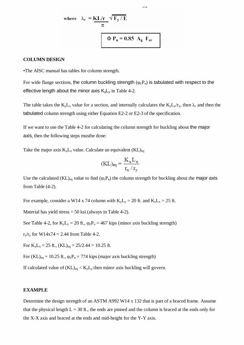
COLUMN DESIGN
•The AISC manual has tables for column strength.
For wide flange sections, the column buckling strength (φcPn) is tabulated with respect to the
effective length about the minor axis KyLy in Table 4-2.
The table takes the KyLy value for a section, and internally calculates the KyLy/ry, then λc and then the
tabulated column strength using either Equation E2-2 or E2-3 of the specification.
If we want to use the Table 4-2 for calculating the column strength for buckling about the major
axis, then the following steps mustbe done:
Take the major axis KxLx value. Calculate an equivalent (KL)eq
Use the calculated (KL)eq value to find (φcPn) the column strength for buckling about the major axis
from Table (4-2).
For example, consider a W14 x 74 column with KyLy = 20 ft. and KxLx = 25 ft.
Material has yield stress = 50 ksi (always in Table 4-2).
See Table 4-2, for KyLy = 20 ft., φcPn = 467 kips (minor axis buckling strength)
rx/ry for W14x74 = 2.44 from Table 4-2.
For KxLx = 25 ft., (KL)eq = 25/2.44 = 10.25 ft.
For (KL)eq = 10.25 ft., φcPn = 774 kips (major axis buckling strength)
If calculated value of (KL)eq < KyLy then minor axis buckling will govern.
EXAMPLE
Determine the design strength of an ASTM A992 W14 x 132 that is part of a braced frame. Assume
that the physical length L = 30 ft., the ends are pinned and the column is braced at the ends only for
the X-X axis and braced at the ends and mid-height for the Y-Y axis.

Solution
• Step I. Calculate the effective lengths.
For W14 x 132: rx = 6.28 in; ry = 3.76 in; Ag =38.8 in2
Kx = 1.0 and Ky = 1.0
Lx = 30 ft. and Ly = 15 ft.
KxLx = 30 ft. and KyLy = 15 ft.
• Step II. Determine the governing slenderness ratio
15
30
15
15
15
15

KxLx/rx = 30 x 12 in./6.28 in.= 57.32
KyLy/ry = 15 x 12 in./3.76 in. = 47.87
The larger slenderness ratio, therefore, buckling about the major axis will govern the column strength.
Step III. Calculate the column strength
KxLx = 30 ft. Therefore, (KL)eq = 30/(6.28/3.76) = 17.96 ft.
(KL)eq > KyLy so it is governs
From Table 4-2, for (KL)eq = 18.0 ft. φcPn = 1300 kips (design column strength)
Step IV. Check the local buckling limits
Therefore, the section is OK.
EXAMPLE
A compression member is subjected to service loads of 165 kips dead load and 535 kips of live load.
The member is 26 ft. long and pinned at each end. Use A992 (50 ksi) steel and select a W shape
Solution
• Calculate the factored design load Pu
Pu = 1.2 PD + 1.6 PL = 1.2 x 165 + 1.6 x 535 = 1054 kips
Select a W shape from the AISC manual Tables
For KyLy = 26 ft. and required strength = 1054 kips
Select W14 x 145. It has φcPn = 1160 kips
Select W12 x 170. It has φcPn = 1070 kips
No W10 will work.
W14 x 145 is the lightest
Note that column sections are usually W12 or W14. Usually sections bigger than W14 are
usually not used as columns.

EFFECTIVE LENGTH OF COLUMNS IN FRAMES
• So far, we have looked at the buckling strength of individual columns. These columns had various
boundary conditions at the ends, but they were not connected to other members with moment (fix)
connections.
• The effective length factor K for the buckling of an individual column can be obtained for the
appropriate end conditions from Table C-C2.1 of the AISC Manual.
• However, when these individual columns are part of a frame, their ends are connected to other
members (beams etc.).
- Their effective length factor K will depend on the restraint offered by the other members connected
at the ends.
- Therefore, the effective length factor K will depend on the relative rigidity (stiffness) of the
members connected at the ends.
The effective length factor for columns in frames must be calculated as follows:
• First, you have to determine whether the column is part of a braced frame or an unbraced (moment
resisting) frame.
- If the column is part of a braced frame then its effective length factor 0 < K ≤ 1
- If the column is part of an unbraced frame then 1 < K ≤ ∞
• Then, you have to determine the relative rigidity factor G for both ends of the column
- G is defined as the ratio of the summation of the rigidity (EI/L) of all columns coming
together at an end to the summation of the rigidity (EI/L) of all beams coming together at the
same end.
• Then, you can determine the effective length factor K for the column using the calculated
value of G at both ends, i.e., GA and GB and the appropriate alignment chart
• There are two alignment charts provided by the AISC manual,

- One is for columns in braced (sidesway inhibited) frames. See Figure C-C2.2a 16.1-191 on the AISC manual. 0 < K ≤ 1
- The second is for columns in unbraced (sidesway uninhibited) frames. See Figure C-C2.2b on the
AISC manual. 1 < K ≤ ∞
- The procedure for calculating G is the same for both cases.
Note:
For pin connection use G = 10
For fixed connection use G = 1
EXAMPLE 3.6 Calculate the effective length factor for the W12 x 53 column AB of the frame
shown below. Assume that the column is oriented in such a way that major axis bending occurs
in the plane of the frame. Assume that the columns are braced at each story level for out-of-plane
buckling. Assume that the same column section is used for the stories above and below.
Step I. Identify the frame type and calculate Lx, Ly, Kx, and Ky if possible.
• It is an unbraced (sidesway uninhibited) frame. • Lx = Ly = 12 ft. • Ky = 1.0

• Kx depends on boundary conditions, which involve restraints due to beams and
columns connected to the ends of column AB.
• Need to calculate Kx using alignment charts.
Step II - Calculate Kx
• Ixx of W 12 x 53 = 425 in4 Ixx of W14x68 = 753
• Using GA and GB: Kx = 1.3 (from Alignment Chart)
Step III - Design strength of the column •
KyLy = 1.0 x 12 = 12 ft.
Kx Lx = 1.3 x 12 = 15.6 ft.
rx / ry for W12x53 = 2.11
(KL)eq = 15.6 / 2.11 = 7.4 ft
KyLy > (KL)eq
Therefore, y-axis buckling governs. Therefore φcPn = 518 kips

Inelastic Stiffness Reduction Factor - Modification
This concept for calculating the effective length of columns in frames was widely accepted for many
years.
Over the past few years, a lot of modifications have been proposed to this method due to its several
assumptions and limitation. Most of these modifications have not yet been accepted in to the AISC
provisions.
One of the accepted modifications is the inelastic stiffness reduction factor. As presented earlier, G is
a measure of the relative flexural rigidity of the columns (EIc/Lc) with respect to the beams (EIb/Lb).
However, if column buckling were to occur in the inelastic range (λc < 1.5), then the flexural rigidity of
the column will be reduced because Ic will be the moment of inertia of only the elastic core of the
entire cross-section. See figure below
The beams will have greater flexural rigidity when compared with the reduced rigidity(EIc) of the
inelastic columns. As a result, the beams will be able to restrain the columns better, which is good for
column design.
This effect is incorporated in to the AISC column design method through the use of Table4-1 given on
page 4-20 of the AISC manual.
Table 4-1 gives the stiffness reduction factor (τ) as a function of the yield stress Fy and the stress Pu/Ag in
the column, where Pu is factored design load (analysis)

EXAMPLE 3.7 Calculate the effective length factor for a W10 x 60 column AB made from 50 ksi
steel in the unbraced frame shown below. Column AB has a design factor load Pu = 450 kips. The
columns are oriented such that major axis bending occurs in the plane of the frame. The columns are
braced continuously along the length for out-of-plane buckling. Assume that the same column
section is used for the story above
Solution
Step I. Identify the frame type and calculate Lx, Ly, Kx, and Ky if possible.
• It is an unbraced (sidesway uninhibited) frame. • Ly = 0 ft. • Ky has no meaning because out-of-plane buckling is not possible.
• Kx depends on boundary conditions, which involve restraints due
to beams and columns
connected to the ends of column AB.
• Need to calculate Kx using alignment charts.

Step II (a) - Calculate Kx
• Ixx of W 14 x 74 = 796 in4 Ixx of W 10 x 60 = 341 in4
• GB = 10 for pin support
• Using GA and GB: Kx = 1.8 - from Alignment Chart
Note, Kx is greater than 1.0 because it is an unbraced frame.
Step II (b) - Calculate Kx- inelastic using stiffness reduction factor method
• Reduction in the flexural rigidity of the column due to residual stress effects
- First calculate, Pu / Ag = 450 / 17.6 = 25.57 ksi
- Then go to Table 4-1 on the manual, and read the value of stiffness reduction factor for Fy = 50 ksi and Pu/Ag = 25.57 ksi.
Stiffness reduction factor = τ = 0.833
• GA-inelastic = τ x GA = 0.833 x 0.609 = 0.507
• GB = 10 - for pin support
• Using GA-inelastic and GB, Kx-inelastic = 1.75 - alignment chart
• Note: You can combine Steps II (a) and (b) to calculate the Kx-inelastic directly. You don’t need
to calculate elastic Kx first. It was done here for demonstration purposes.
• Note that Kx-inelastic< Kx. This is in agreement with the fact that the beams offer better resistance to
the inelastic column AB because it has reduced flexural rigidity.
Step III - Design strength of the column • KxLx = 1.75 x 15 = 26.25 ft.
- rx / ry for W10x60 = 1.71 - from Table 4-2
- (KL)eq = 26.25/1.71 = 15.35 ft.
• φcPn for X-axis buckling = 513.9 kips - from Table 4-2

• Section slightly over designed for Pu = 450 kips.
Column design strength = φcPn = 513.9 kips
EXAMPLE:
• Design Column AB of the frame shown below for a design load of 500 kips. • Assume that the column is oriented in such a way that major axis bending occurs in the plane of the frame. • Assume that the columns are braced at each story level for out-of-plane buckling. • Assume that the same column section is used for the stories above and below.
Step I - Determine the design load and assume the steel material.
• Design Load = Pu = 500 kips
• Steel yield stress = 50 ksi (A992 material)
Step II. Identify the frame type and calculate Lx, Ly, Kx, and Ky if possible.
• It is an unbraced (sidesway uninhibited) frame.
• Lx = Ly = 12 ft.
• Ky = 1.0
• Kx depends on boundary conditions, which involve restraints due to beams and
columns connected to the ends of column AB.
• Need to calculate Kx using alignment charts.
• Need to select a section to calculate Kx

Step III - Select a column section
• Assume minor axis buckling governs.
• Ky Ly = 12 ft.
• See Column Tables in AISC-LRFD manual Select section W12x53
• φcPn for y-axis buckling = 518 kips
Step IV - Calculate Kx-inelastic
• Ixx of W 12 x 53 =425 in4 Ixx of W14x68 = 753 in4
• Account for the reduced flexural rigidity of the column due to residual stress effects
- Pu/Ag = 500 / 15.6 = 32.05 ksi
- Stiffness reduction factor = τ = 0.58
• Using GA and GB: Kx-inelastic = 1.2 - from Alignment Chart
Step V - Check the selected section for X-axis buckling •
• Kx Lx = 1.2 x 12 = 14.4 ft.
• rx / ry for W12x53 = 2.11
• Calculate (KL)eq to determine strength (φcPn) for X-axis buckling (KL)eq = 14.4 / 2.11 = 6.825 ft.
• From the column design tables, φcPn for X-axis buckling = 612.3 kips Step VI. Check the local buckling limits
Therefore, the section is non-compact. OK, local buckling is not a problem

Step VII - Summarize the solution
EXAMPLE 3.9
• Design Column AB of the frame shown below for a design load of 450 kips.
• Assume that the column is oriented in such a way that major axis bending occurs in
the plane of the frame.
• Assume that the columns are braced continuously along the length for out-of-plane buckling.
• Assume that the same column section is used for the story above.
Step I - Determine the design load and assume the steel material.
• Design Load = Pu = 450 kips
• Steel yield stress = 50 ksi
Step II. Identify the frame type and calculate Lx, Ly, Kx, and Ky if possible.
• It is an unbraced (sidesway uninhibited) frame.
• Ly = 0 ft.
• Ky has no meaning because out-of-plane buckling is not possible.
• Kx depends on boundary conditions, which involve restraints due to beams and

columns connected to the ends of column AB.
• Need to calculate Kx using alignment charts.
• Need to select a section to calculate Kx
Step III. Select a section
• There is no help from the minor axis to select a section
• Need to assume Kx to select a section.
See Figure below:
• The best case scenario for Kx is when the beams connected at joint A have infinite
flexural
stiffness (rigid). In that case Kx = 2.0 from Table C-C2.1
• Actually, the beams don't have infinite flexural stiffness. Therefore, calculated Kx
should be greater than 2.0.
• To select a section, assume Kx = 2.0
- KxLx = 2.0 x 15.0 ft. = 30.0 ft.
• Need to be able to calculate (KL)eq to be able to use the column design tables to select a section. Therefore, need to assume a value of rx/ry to select a section.
- See the W10 column tables.
- Assume rx/ry = 1.71, which is valid for W10 x 49 to W10 x 68.
• (KL)eq = 30.0/1.71 = 17.54 ft.
- Obviously from the Tables, for (KL)eq = 17.5 ft., W10 x 60 is the first section that will have φcPn > 450 kips
• Select W10x60 with φcPn = 457.7 kips for (KL)eq = 17.5 ft.

Step IV - Calculate Kx-inelastic using selected section
• Ixx of W 14 x 74 = 796 in4 Ixx of W 10 x 60 = 341 in4
• Account for the reduced flexural rigidity of the column due to residual stress
effects
- Pu/Ag = 450 / 17.6 = 25.57 ksi
- Stiffness reduction factor = τ = 0.833
• GB = 10 - for pin support
• Using GA and GB: Kx-inelastic = 1.75 - from Alignment Chart
• Calculate value of Kx-inelastic is less than 2.0 (the assumed value) because GB was
assumed to be equal to 10 instead of ∞
Step V - Check the selected section for X-axis buckling
• Kx Lx = 1.75 x 15 = 26.25 ft.
- rx / ry for W10x60 = 1.71
- (KL)eq = 26.25/1.71 = 15.35 ft.
- (φcPn) for X-axis buckling = 513.9 kips
• Section slightly over-designed for Pu = 450 kips.
• W10 x 54 will probably be adequate, Student should check by calculating Kx
inelastic and φcPn for that section.
Step VI. Check the local buckling limits
Therefore, the section is non-compact. OK, local buckling is not a problem

• Step VII - Summarize the solution
TORSIONAL AND FLEXURAL-TORSIONAL BUCKLING Compression members can have three different modes of failure
1- Flexural buckling (Euler buckling Global buckling), it depends on the slenderness ratio (KL/r) and end conditions.
2- Local buckling occurs when some part of cross section are so thin that can buckle locally in compression before flexural buckling occur. 3- Torsional buckling may occur in columns having certain cross sections, where the shear center does not coincide with the center of gravity. These columns failed by twisting or combination of torsion and flexural buckling
Flexural-torsional buckling Flexural buckling
Flexural buckling will occur about the x-axis
Flexural-torsional buckling will occur about the y and z-axis
Smaller of the two will govern the design strength.

When an axially loaded member becomes unstable overall (no local buckling) it buckles one of the three following ways
Torsional Buckling: this type of failure is caused by twisting about longitudinal axis of membe. It can be occure only with doubly symmetrical cross sections with very slender cross-sectional elements. Standard Hot-Rolled Shapes are NOT susceptible to torsional bukling, but built-up members should be investigated. The cruciform shape is particularly vulnerable to this type of buckling.
The design procedure in this type based on the use of λe instead of λc.
Where,
Cw = Warping Constant (in6)
G = Shear Modulus (11,200 ksi for structural steel)
J = Torsional Constant
Kz = Effective Length Factor for Torsional Buckling (based on end restraints against twisting)
Flexural Torsional Buckling: this type of failure is caused by a combination of flexural and torsional buckling and occurs only in unsymmetrical cross sections such as:
• Axis of Symmetry: channels, structural tees, double-angle, equal length single angles.
( ) yxz
we IIGJLK
ECF
+
+=
12
2π
e
y
FF
e =λ
P
P

• No Axis of Symmetry: unequal length single angles.
The design procedure in this type based on the use of λe instead of λc.
A - Axis of Symmetry
Where xo and yo are the coordinates of shear center with respect to centroid of section
B – No Axis of Symmetry:
Fe is the lowest root of the Cubic equation
Values of these constants for different shapes can be found in the table of torsion propertiesand flexural-torsional properties in Part 1 of the Manual.
+−−
+=
2411
2 ezey
ezeyezeye FF
HFFH
FFF
( ) 22
2 1
ogz
wez
rAGJ
LKEC
F
+=
π
( )2
2
yyey rLK
EF π=
2
22
1o
oo
r
yxH
+−=
g
yxooo
AII
yxr+
++= 222
( )( )( ) ( ) ( ) 02
22
2 =
−−
−−−−−
o
oexee
o
oeyeeezeeyeexe r
yFFF
rx
FFFFFFFFF
Shear Center
00 =x
20ft
yy −=

EXAMPLE
Calculate the design compressive strength of a WT10.5 x 66. The effective length with respect to x-
axis is 25.5 ft. The effective length with respect to the y-axis is 20 ft. and the effective length with
respect to z-axis is 20ft. A992 steel is used.
Solution
• Step I. Buckling strength about x-axis
Values for Ag and rx from the manual.
• Step II. Flexural-torsional buckling about the y and z axes - Calculate Fcry and Fcrz then calculate Fcrft and φcPn
• Step III. Design strength and check local buckling

Local buckling is not a problem. Design strength = 397.2 kips. X-axis flexural buckling
governs.
BUILT–UP MEMBERS
If the cross-sectional properties of a built-up compression member are known, its analysis is the same
as for any other compression member.
One of the most important considration in the built-up members is the connection problems.
Example 4.15 in page 121 explains the design procedure for this type of columns.
Connection Requirements for Built-Up Members Ccomposed of Rolled Shapes
The most common bult-up shape is the double angle shape.
Double-angle sections are very popular as compression members in trusses and bracing members in
frames.
These sections consist of two angles placed back-to-back and connected together using bolts or welds.
You have to make sure that the two single angle sections are connected such that they do not buckle
(individually) between the connections along the length.
If the member buckles about the x-axis (flexural buckling), the connectors are not subjected to any
calculated load.
To ensure that the built-up members acts as a unit, the AISC specification requires that Ka/rz of the
individual single angles < ¾ of the governing KL/r of the double angle.
where, a is the distance between connections and rz is the smallest radius of gyration of the single
angle.
Double-angle sections can fail by flexural buckling about the x-axis or flexural torsional buckling
about the y and z axes.

For flexural torsional buckling, there is a slight problem.
The connectors are subjected to shearing forces.
According to AISC Specification, a modified (KL/r)m must be calculated for the double angle section
for buckling about the y-axis to account for this problem.
AISC considers two categories of connectors:
• Snug-tight bolts
• Welds or fully tightened bolts
A- Intermediate connectors that are snug-tight bolted
B- Intermediate connectors that are welded or fully tensioned bolted:
where, α = separation ratio = h/2ry h = distance between component centroids in the y direction
EXAMPLE
Calculate the design strength of the compression member shown in the figure. Two angles, 5 x 3 x ½
are oriented with the long legs back-to-back and separated by 3/8 in. The effective length KL is16 ft.
A36 steel is used. Assume three welded intermediate connectors.

Solution
Step I. Determine the relevant properties from the AISC manual
Step II. Calculate the x-axis buckling strength
KL/rx = 16 x 12 /1.58 = 120.8
Step III. Calculate (KL/r)m for y-axis buckling (KL/r) = 16 x 12/1.24 = 154.8 a = 16*12/4spaces = 48 in a/rz = 48/0.642 = 74.77 a/rz = 74.77 < 0.75 x KL/r = 0.75 x 154.8 = 116.1 (OK) α = h/2ry = (2 x 0.746 + (3/8))/(2 x 0.824) = l.131
16 in
a a a a

Step IV. Calculate flexural torsional buckling strength.
Flexural torsional buckling strength controls.
The design strength of the double angle member is 62.1 kips.
Step V. Compare with design strengths in Table 4-10 of the AISC manual
φcPn for x-axis buckling with unsupported length = 16 ft. = 106 kips
φcPn for y-z axis buckling with unsupported length = 16 ft. = 61.3 kips
These results make indicate excellent correlation between the calculations in steps II to IV
and the tabulated values.
)تلك الدار اآلخرة نجعلھا للذین ال یریدون علوا في األرض وال فسادا والعاقبة للمتقین(
أسأل اهللا أن نكون وایاكم منھم