Chapter 35 Lecture Nine: Interference of Light Waves: I HW 3 (problems): 34.40, 34.43, 34.68, 35.2,...
30
Chapter 35 Lecture Nine: Interference of Light Waves: I HW 3 (problems): 34.40, 34.43, 34.68, 35.2, 35.9, 35.16, 35.26, 35.40, Due Friday, Sept. 25
-
Upload
pauline-lilian-gibson -
Category
Documents
-
view
214 -
download
1
Transcript of Chapter 35 Lecture Nine: Interference of Light Waves: I HW 3 (problems): 34.40, 34.43, 34.68, 35.2,...

Chapter 35
Lecture Nine:
Interference of Light Waves: I
HW 3 (problems): 34.40, 34.43, 34.68, 35.2, 35.9, 35.16, 35.26, 35.40,
Due Friday, Sept. 25

Wave Optics
Wave optics is a study concerned with phenomena that cannot be adequately explained by geometric (ray) optics
These phenomena include: Interference Diffraction Polarization

Interference
In constructive interference the amplitude of the resultant wave is greater than that of either individual wave
In destructive interference the amplitude of the resultant wave is less than that of either individual wave
All interference associated with light waves arises when the electromagnetic fields that constitute the individual waves combine

Conditions for Interference
To observe interference in light waves, the following two conditions must be met: 1) The sources must be coherent
They must maintain a constant phase with respect to each other
2) The sources should be monochromatic Monochromatic means they have a single wavelength

Producing Coherent Sources
Light from a monochromatic source is used to illuminate a barrier
The barrier contains two narrow slits The slits are small openings
The light emerging from the two slits is coherent since a single source produces the original light beam
This is a commonly used method

Young’s Double-Slit Experiment: Schematic
Thomas Young first demonstrated interference in light waves from two sources in 1801
The narrow slits S1 and S2 act as sources of waves
The waves emerging from the slits originate from the same wave front and therefore are always in phase

Resulting Interference Pattern The light from the two slits
forms a visible pattern on a screen
The pattern consists of a series of bright and dark parallel bands called fringes
Constructive interference occurs where a bright fringe occurs
Destructive interference results in a dark fringe
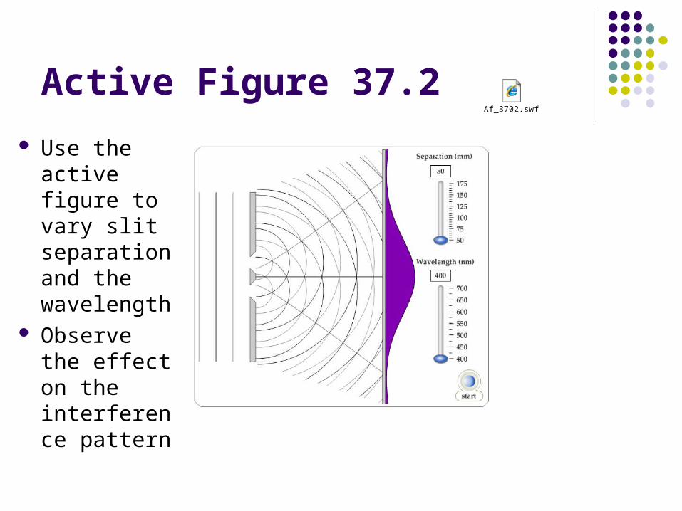
Active Figure 37.2
Use the active figure to vary slit separation and the wavelength
Observe the effect on the interference pattern
Af_3702.swf

Interference Patterns
Constructive interference occurs at point P
The two waves travel the same distance Therefore, they arrive in
phase As a result, constructive
interference occurs at this point and a bright fringe is observed

Interference Patterns, 2 The lower wave has to
travel farther than the upper wave to reach point P
The lower wave travels one wavelength farther Therefore, the waves arrive
in phase A second bright fringe
occurs at this position

Interference Patterns, 3 The upper wave travels
one-half of a wavelength farther than the lower wave to reach point R
The trough of the upper wave overlaps the crest of the lower wave
This is destructive interference A dark fringe occurs
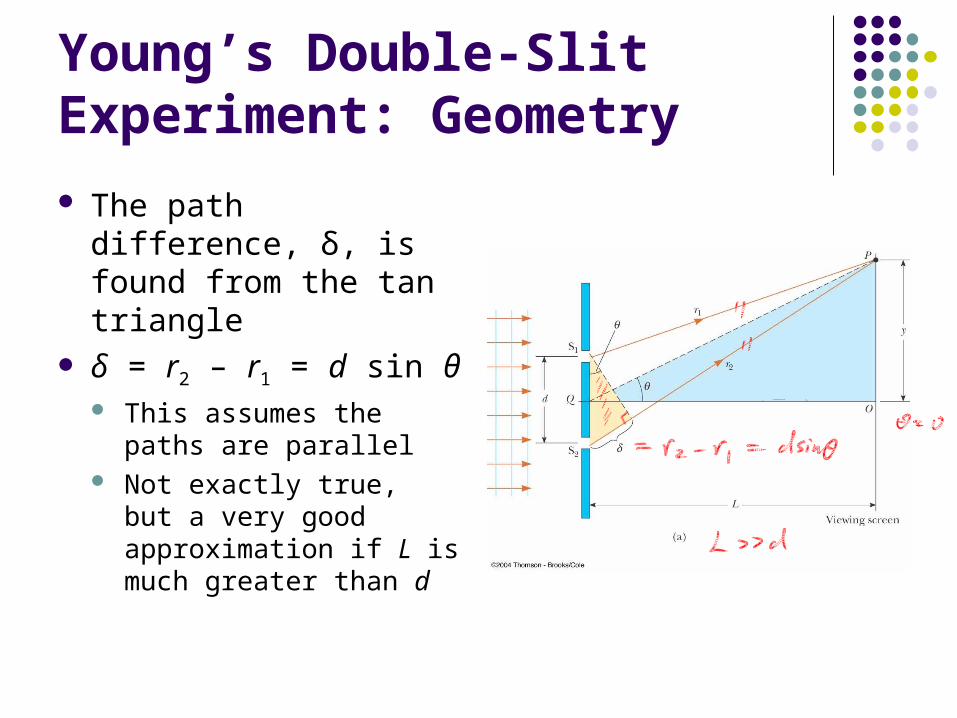
Young’s Double-Slit Experiment: Geometry
The path difference, δ, is found from the tan triangle
δ = r2 – r1 = d sin θ This assumes the paths
are parallel Not exactly true, but a
very good approximation if L is much greater than d
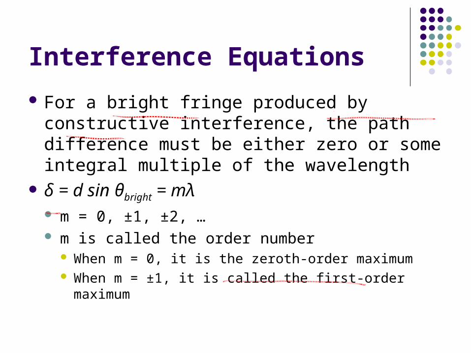
Interference Equations
For a bright fringe produced by constructive interference, the path difference must be either zero or some integral multiple of the wavelength
δ = d sin θbright = mλ m = 0, ±1, ±2, … m is called the order number
When m = 0, it is the zeroth-order maximum When m = ±1, it is called the first-order maximum

Interference Equations, 2
When destructive interference occurs, a dark fringe is observed
This needs a path difference of an odd half wavelength
δ = d sin θdark = (m + ½)λ m = 0, ±1, ±2, …

Interference Equations, 4
The positions of the fringes can be measured vertically from the zeroth-order maximum
Using the blue triangle ybright = L tan bright
ydark = L tan dark

Interference Equations, final
Assumptions in a Young’s Double Slit Experiment L >> d d >> λ
Approximation: θ is small and therefore the small angle approximation
tan θ ~ sin θ can be used y = L tan θ ≈ L sin θ For bright fringes bright ( 0 1 2 ), ,
λLy m m
d

Uses for Young’s Double-Slit Experiment
Young’s double-slit experiment provides a method for measuring wavelength of the light
This experiment gave the wave model of light a great deal of credibility It was inconceivable that particles of light could
cancel each other in a way that would explain the dark fringes

Example, Double-slit Interference Pattern:
ybright = D tan bright
ydark = D tan dark

Example, Double-slit interference pattern:

Intensity Distribution: Double-Slit Interference Pattern
The bright fringes in the interference pattern do not have sharp edges The equations developed give the location of only
the centers of the bright and dark fringes We can calculate the distribution of light
intensity associated with the double-slit interference pattern

Intensity Distribution, Assumptions
Assumptions: The two slits represent coherent sources of
sinusoidal waves The waves from the slits have the same angular
frequency, ω The waves have a constant phase difference, φ
The total magnitude of the electric field at any point on the screen is the superposition of the two waves

Intensity Distribution, Electric Fields
The magnitude of each wave at point P can be found E1 = Eo sin ωt
E2 = Eo sin (ωt + φ) Both waves have the
same amplitude, Eo

Intensity Distribution, Phase Relationships
The phase difference between the two waves at P depends on their path difference δ = r2 – r1 = d sin θ
A path difference of λ (for constructive interference) corresponds to a phase difference of 2π rad
A path difference of δ is the same fraction of λ as the phase difference φ is of 2π
This gives 2 2
sin π π
φ δ d θλ λ

Intensity Distribution, Resultant Field
The magnitude of the resultant electric field comes from the superposition principle EP = E1+ E2 = Eo[sin ωt + sin (ωt + φ)]
This can also be expressed as
EP has the same frequency as the light at the slits The magnitude of the field is multiplied by the
factor 2 cos (φ / 2)
2 cos sin2 2P o
φ φE E ωt
2 2 sin
π πφ δ d θ
λ λ

Intensity Distribution, Equation
The expression for the intensity comes from the fact that the intensity of a wave is proportional to the square of the resultant electric field magnitude at that point
The intensity therefore is
2 2max max
sin cos cos
πd θ πdI I I y
λ λL

Light Intensity, Graph
The interference pattern consists of equally spaced fringes of equal intensity
This result is valid only if L >> d and for small values of θ

Lloyd’s Mirror
An arrangement for producing an interference pattern with a single light source
Waves reach point P either by a direct path or by reflection
The reflected ray can be treated as a ray from the source S’ behind the mirror

Interference Pattern from a Lloyd’s Mirror
This arrangement can be thought of as a double-slit source with the distance between points S and S’ comparable to length d
An interference pattern is formed The positions of the dark and bright fringes
are reversed relative to the pattern of two real sources
This is because there is a 180° phase change produced by the reflection

Phase Changes Due To Reflection
An electromagnetic wave undergoes a phase change of 180° upon reflection from a medium of higher index of refraction than the one in which it was traveling Analogous to a pulse on
a string reflected from a rigid support
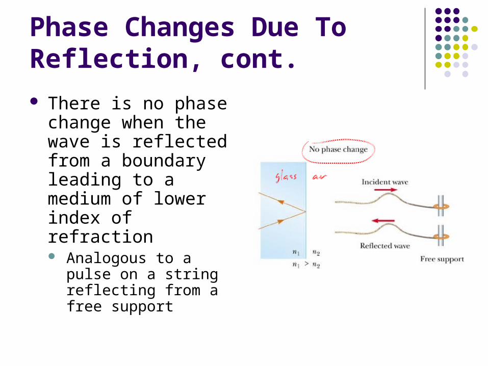
Phase Changes Due To Reflection, cont.
There is no phase change when the wave is reflected from a boundary leading to a medium of lower index of refraction Analogous to a pulse on
a string reflecting from a free support