
Chapter 35 Interference Masatsugu Sei Suzuki Department of...
33
Chapter 35 Interference Masatsugu Sei Suzuki Department of Physics, SUNY at Binghamton (Date: August 10, 2018) 1. Huygen’s principle Every point on a primary wavefront serves as the source of spherical secondary wavelets such that the primary wavefront at some later time is the envelope of these wavelets. Moreover, the wavelets advance with a speed and frequency equal to that of the primary wave at each point in space. If the medium is homogeneous the wavelets may be constructed with finite radii, whereas if it is inhomogeneous the wavelets will have to have infinitesimal radii. Figure shows a view of a wavefront as well as a number of spherical secondary wavelets which, after a time t, have propagated out to a radius of vt. The envelope of all of these wavelets is then asserted to correspond to the advanced primary wave ’.
Transcript of Chapter 35 Interference Masatsugu Sei Suzuki Department of...

Chapter 35
Interference
Masatsugu Sei Suzuki
Department of Physics, SUNY at Binghamton
(Date: August 10, 2018)
1. Huygen’s principle
Every point on a primary wavefront serves as the source of spherical secondary wavelets such that the primary wavefront at some later time is the envelope of these wavelets. Moreover, the wavelets advance with a speed and frequency equal to that of the primary wave at each point in space.
If the medium is homogeneous the wavelets may be constructed with finite radii, whereas if it is inhomogeneous the wavelets will have to have infinitesimal radii. Figure shows a view of a wavefront as well as a number of spherical secondary wavelets which, after a time t, have propagated out to a radius of vt. The envelope of all of these wavelets is then asserted to correspond to the advanced primary wave ’.

Fig. Huygens’s principle
Every point (red dot) on a primary wavefront (red circle) serves as the source of spherical secondary wavelets such that the primary wavefront at some later time is the envelope of these wavelets.
2. Diffraction by a double slit

(a) Analysis in the complex plane
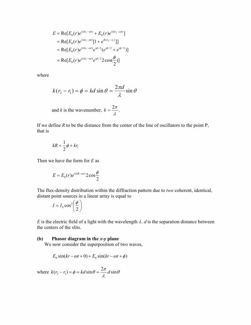
The sum of the interfering spherical wavelets yields an electric field at P, given by the real part of
)]2
cos(2)(Re[
)]()(Re[
]]1[)(Re[
])()(Re[
2/)(0
2/2/2/)(0
)()(0
)(0
)(0
1
1
121
21
itkri
iiitkri
rriktkri
tkritkri
eerE
eeeerE
eerE
erEerEE
where
sin2
sin)( 12
dkdrrk
and k is the wavenumber, 2
k .
If we define R to be the distance from the center of the line of oscillators to the point P, that is
12
1krkR
Then we have the form for E as
2cos2)( )(
0
tkRierEE
The flux-density distribution within the diffraction pattern due to two coherent, identical, distant point sources in a linear array is equal to
2
cos20
II
E is the electric field of a light with the wavelength . d is the separation distance between the centers of the slits. (b) Phasor diagram in the x-y plane
We now consider the superposition of two waves,
0 0sin( 0) sin( )E kr t E kr t
where
sin2
sin)( 12 dkdrrk
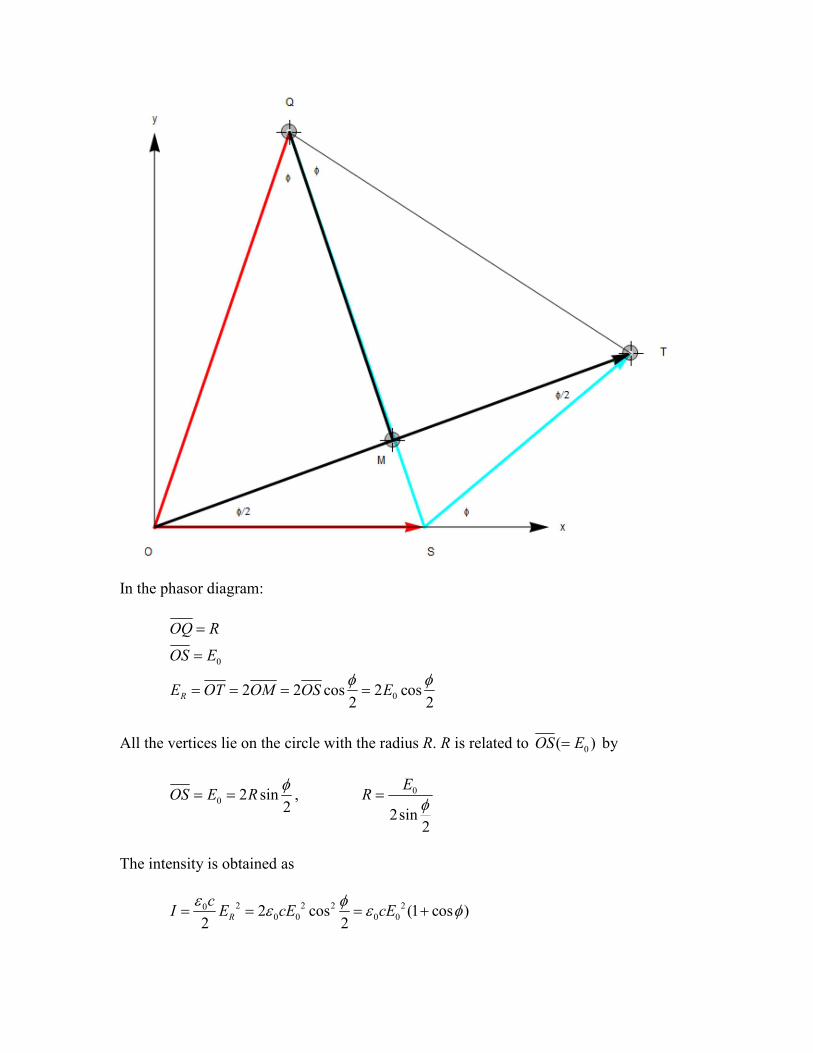
In the phasor diagram:
0
02 2 cos 2 cos2 2
R
OQ R
OS E
E OT OM OS E
All the vertices lie on the circle with the radius R. R is related to 0( )OS E by
0 2 sin2
OS E R
, 0
2sin2
ER
The intensity is obtained as
2 2 2 200 0 0 02 cos (1 cos )
2 2R
cI E cE cE

or
02 (1 cos )I I
where 2
0 00 2
cEI
, and the phase difference is given by
sin2d
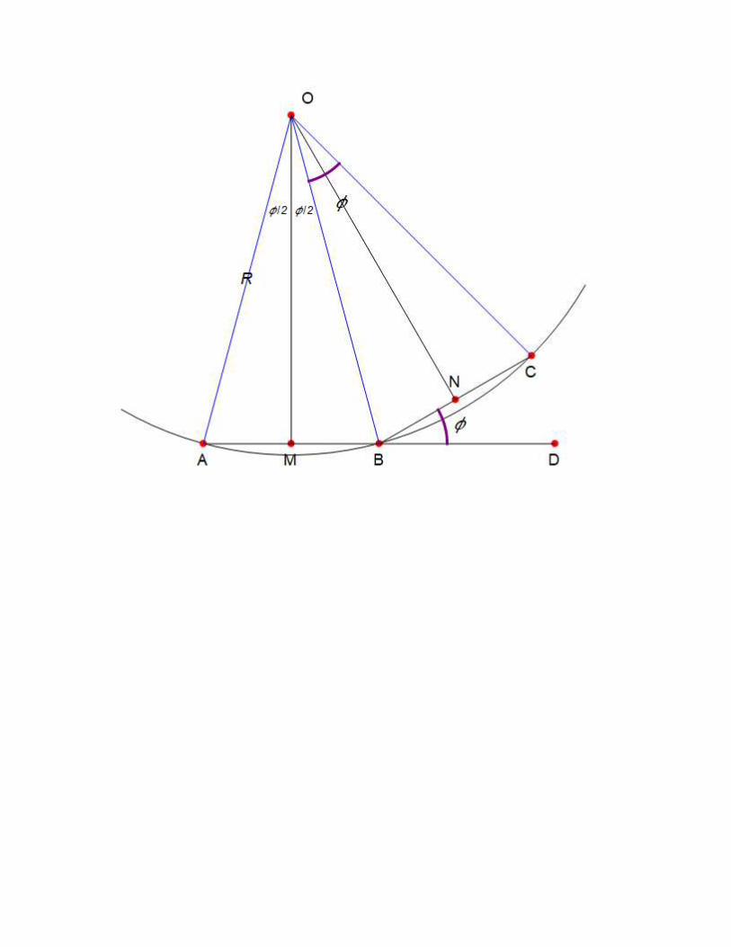
((Note)) Geometrics Proof of the geometry for the phasor diagram

We consider two isosceles triangles.
QTSQSTQSOQOS
RQTQSQO
In other words, points O, S, and T lie on a circle with radius R (the value of R will be specified later). We assume that
TSU
From the geometry shown in the Fig, we have
2
2
Then we get
The radius R and the side OS are related as
2sin2
2sin2
RROS .
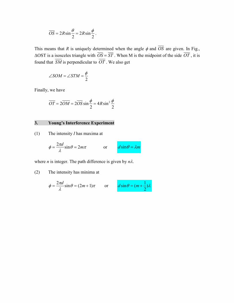
This means that R is uniquely determined when the angle and OS are given. In Fig.,
ΔOST is a isosceles triangle with STOS . When M is the midpoint of the side OT , it is
found that SM is perpendicular to OT . We also get
2
STMSOM
Finally, we have
22 2 sin 4 sin2 2
OT OM OS R
3. Young’s Interference Experiment
(1) The intensity I has maxima at
md
2sin2
or md sin
where n is integer. The path difference is given by n. (2) The intensity has minima at
)12(sin2
md
or )2
1(sin md
The vertical distance y on the screen (the distance between the slits S1 and S2, and the screen is D) is given by
sintan DDy
The maximum’s vertical distance yn from the center of the pattern on the screen is
nd
Dyn
. (bright lines)
The minimum’s vertical distance yn from the center of the pattern on the screen is
)2
1( n
d
Dyn
. (dark lines)
((Note))

2
)cos1(0
II
The phase
sin2d
is expressed in terms of y,
yD
ddd
2
tan2sin2
since tanDy . Since f s proportional to y, the intensity is also a periodic function of y.
5. Interference from thin film
(i) The refraction at an interface never causes a phase change. (ii) The reflection can, depending on the indexes of refraction on the two sides of the
interface. When light traveling in a medium of the index of refraction (n1) is reflected from a medium of index n2, it undergoes a phase shift if n2>n1, and it undergoes no phase change.
(iii) When light of the wavelength travels in a medium (with the index of refraction n), its wavelength is n = /n.
We assume that n2>n1 and n2>n3. The phase of ray 1, 1 =
The phase of ray 2, 2 = )/(
)2(2
2n
L
where 2/ n is the wavelength in the medium with the index of refraction n2.
Then the phase difference is
212
4n
L
Maximum reflection (bright film))
)2
1(2
24
2
2
mLn
mnL
Minimum reflection (dark film)
mLn
mnL
2
2
2
)12(4
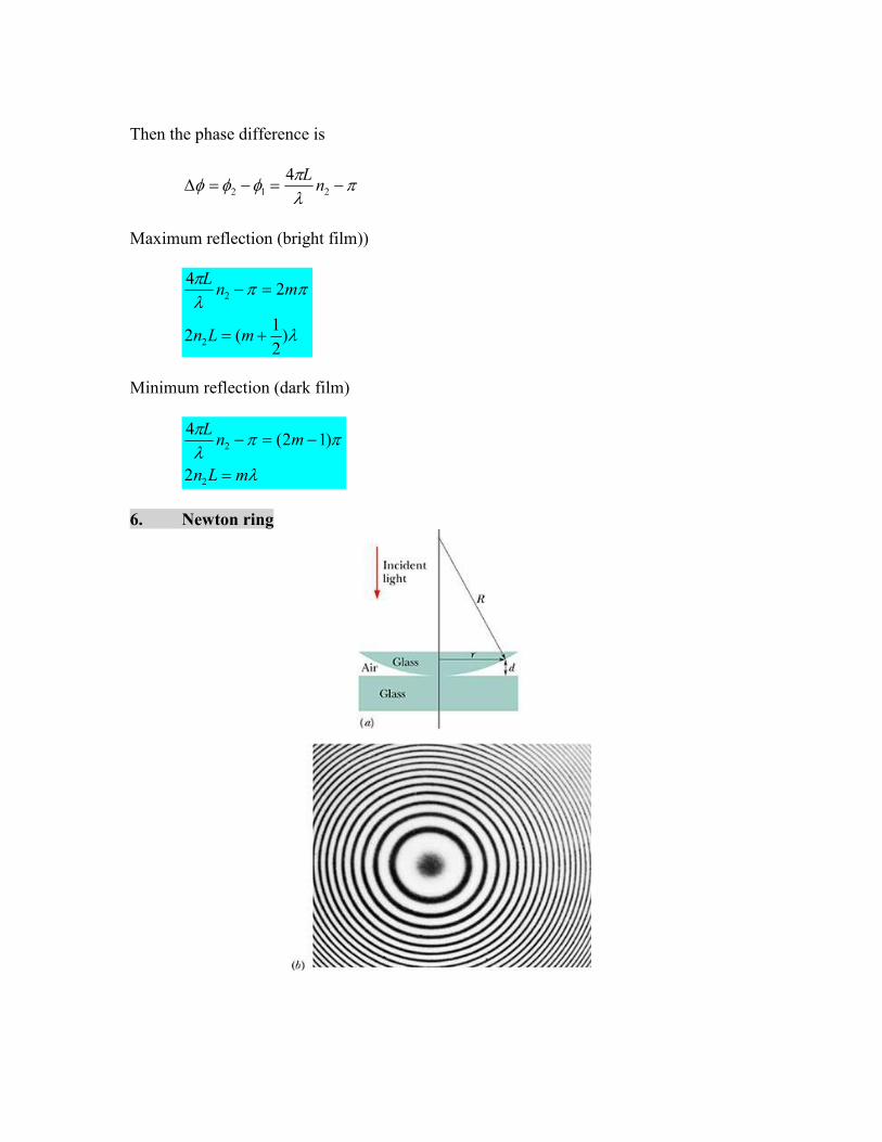
6. Newton ring

From the geometry, we have
R
rd
RRr
RRRRd
2
sin
222
2sin2)cos1(
2
22
2
or
dRr 2 The phase of the ray 1 reflecting at the lower glass
)2(2
1 d

The phase of the ray 2 reflecting at the upper glass
02
The phase difference between two rays is
)2(2
12 d
Bright ring
RmdRr
md
md
)2
1(2
)2
1(2
)1(2)2(2
where m = 0, 1, 2, …… Dark ring
mRdRr
md
md
2
2
)2
1(2)2(
2
where m = 0, 1, 2, 3,…. ((Note)) Beautiful newton ring; see the Wekipedia
http://en.wikipedia.org/wiki/Newton%27s_rings 7. Lloyd’s mirror

An arrangement for producing an interference pattern with a single light source. Waves
reach point P either by a direct path or by reflection. The reflected ray can be treated as a ray from the source S’ behind the mirror. This arrangement can be thought of as a double slit source with the distance between points S and S’ comparable to length d.
An interference pattern is formed. The positions of the dark and bright fringes are reversed relative to pattern of two real sources. This is because there is a 180° phase change produced by the reflection ((Example)) Problem 35-87
In Fig., a microwave transmitter at hight a above the water level of a wide lake transmits microwaves of wavelength toward a receiver on the opposite shore, a distance x above the water level. The microwaves reflecting from the water interfere with the microwaves arriving directly from the transmitter. Assuming that the lake width D is much greater than a and x, and that ≥a, find an expression that gives the values of x for which the signal at the receiver is maximum.

]2
)(1[
)(1)(
]2
)(1[
)(1)(
2
2
2
222
2
2
2
2
222
1
D
axD
D
axDDxaBDCDACr
D
axD
D
axDDxaADr
Then the path difference r (= r2 – r1) is obtained as
D
axax
D
axaxD
D
axD
D
axDrrr
24
2
1
])()[(2
1
]2
)(1[]
2
)(1[
22
2
2
2
2
12
The phase difference between two rays is
)1(2)(2
12 mrr
(Constructive)
where m is an integer. Here we take into account of the phase change by on the reflection of the ray 2 at the point C. Then we have
)2
1(
2
)2
1(2
22
ma
Dx
mD
ax
8. Michelson’s interferometer
8.1 Method
The basic design of the Michelson interferometer is shown in Fig.1. The light beam from the arc source (Hg or Na) is separated in two parts by the partly silvered surface P. At this point, half the beam is reflected to M1 and the other half is transmitted to M2.
Mirrors M1 and M2 reflect the light back to the half silvered plate, and half of each beam
reaches the observer, the remainder being directed back to the source and lost. The mirror M1 can be translated toward or away from the observer by means of micrometer. The
calibration of the micrometer reading is necessary.
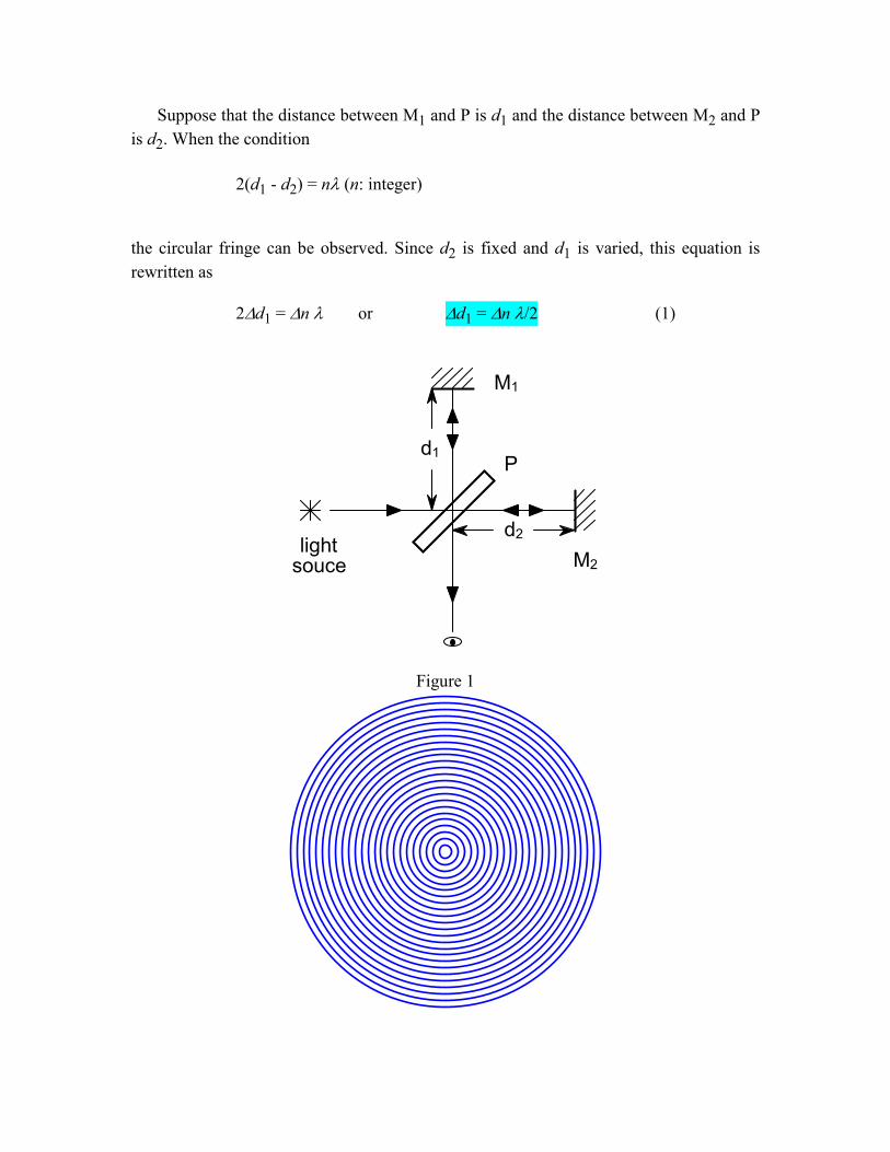
Suppose that the distance between M1 and P is d1 and the distance between M2 and P
is d2. When the condition
2(d1 - d2) = n(n: integer)
the circular fringe can be observed. Since d2 is fixed and d1 is varied, this equation is
rewritten as
2d1 = n or d1 = n /2 (1)
Figure 1
M1
M2
d1
d2
P
light souce
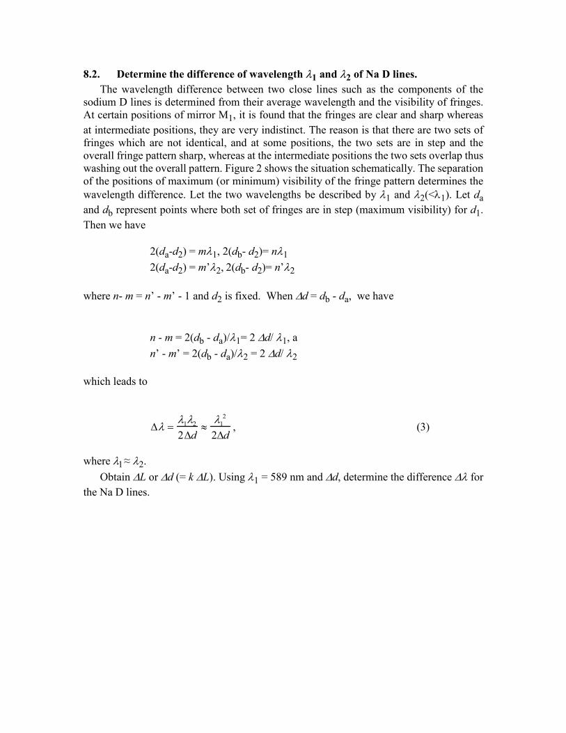
8.2. Determine the difference of wavelength 1 and 2 of Na D lines.
The wavelength difference between two close lines such as the components of the sodium D lines is determined from their average wavelength and the visibility of fringes. At certain positions of mirror M1, it is found that the fringes are clear and sharp whereas
at intermediate positions, they are very indistinct. The reason is that there are two sets of fringes which are not identical, and at some positions, the two sets are in step and the overall fringe pattern sharp, whereas at the intermediate positions the two sets overlap thus washing out the overall pattern. Figure 2 shows the situation schematically. The separation of the positions of maximum (or minimum) visibility of the fringe pattern determines the wavelength difference. Let the two wavelengths be described by 1 and 2(<1). Let da
and db represent points where both set of fringes are in step (maximum visibility) for d1.
Then we have
2(da-d2) = m1, 2(db- d2)= n1
2(da-d2) = m’2, 2(db- d2)= n’2
where n- m = n’ - m’ - 1 and d2 is fixed. When d = db - da, we have
n - m = 2(db - da)/1= 2d/1, a
n’ - m’ = 2(db - da)/2 = 2d/2
which leads to
12
2d
12
2d, (3)
where ≈ 2.
Obtain L or d (= k L). Using 1 = 589 nm and d, determine the difference for
the Na D lines.
Figure 2
8.3. Physical meaning of Na D lines
Consider a sodium atom. From standard atomic spectroscopy notation, the ground-state configuration is (1s)2(2s)2(2p)6(3s). The inner 10 electrons can be visualized to form a spherically symmetrical electron cloud. We are interested in the excitation of the eleventh electron from 3s to a possible higher state. The nearest possibility is excitation to 3p. Because the central potential is no longer of the pure Coulomb form, 3s and 3p are now split. The fine structure brought by spin orbit coupling (VLS) refers to even a finer split
within 3p, between 3p1/2 and 3p3/2, where the subscript refers to j. Experimentally, we observe two closely separated yellow lines- known as the sodium D lines- one at 589.6 nm, the other at 589.0 nm.
1
2 (< 1)
mn
m db
n da
da
db

9. Fabry-Perot Interferometer (Physics Department, Junior Laboratory
The Fabry-Perot interferometer, devised by C. Fabry and A. Perot in 1899, employs multiple-beam interference. It is used to measure wavelengths with high precision and to study the fine structure of spectrum lines. A Fabry-Perot interferometer consists essentially of two optically flat, partially reflecting plates of glass or quartz with their reflecting surfaces held accurately parallel. If the plate spacing can be mechanically varied, the device is called an interferometer, whereas if the plates are held fixed by spacers, it is called an etalon. The surfaces must be extremely flat and parallel in order to obtain the maximum fringe sharpness. We consider the case of the Fabry-Perot etalon (Fig.1). In this case the interference occurs when the condition
2t = n, (1) is satisfied, where t is the thickness of parallel plate, is the wavelength of the light source, and n is an integer.
Fig. Arrangements for the Fabry-Perot etalon 10. Typical problems
10.1 Problem 35-31
Three electromagnetic waves travel through a certain point P along an x axis. They are polarized parallel to a y axis, with the following variations in their amplitudes. Find their resultant at P.
3P3/2
3P1/2
3S1/2
= 589.6 nm= 589.0 nm
Doublet or “fine” structure{

]0.45)/100.2sin[()/00.5(
]0.45)/100.2sin[()/00.5(
])/100.2sin[()/0.10(
143
142
141
tsradmVE
tsradmVE
tsradmVE
((Solution)) = 2.0 x 10¹⁴ ead/s OA = 5 OB = 10 OC = 5 = 45° We use the phasor diagram.
From the symmetry, the resultant y-component is equal to zero.
The resultant x-component = 2 x (5cos45°) + 10 = 2510
)0sin(1.17)0sin()2510( ttEtotal
10.2 Problem 35-78

A thin film of liquid is held in a horizontal circular ring, with air on both sides of the film. A beam of light at wavelength 550 nm is directed perpendicularly onto the film, and the intensity I of its reflection is monitored. Figure gives intensity I as a function of time t; the horizontal scale is set by ts = 20.0 s. The intensity changes because of evaporation from the the two sides of the film. Assume that the film is flat and has parallel sides, a radius of 1.80 cm, and an index of refraction of 1.40. Also assume that the film’s volume decreases at a constant rate. Find the rate.
((Solution)) = 550 nm r = 1.80 cm n = 1.40 period = 12 s.
The constructive interference:
)1(2)2(2
mnd
)2
1(43.196)
2
1(
40.12
550)
2
1(
2
1
mmm
nd [nm]
or
nmd 43.196 The rate of the volume change:
smt
dr
t
V/1066.1 311
2
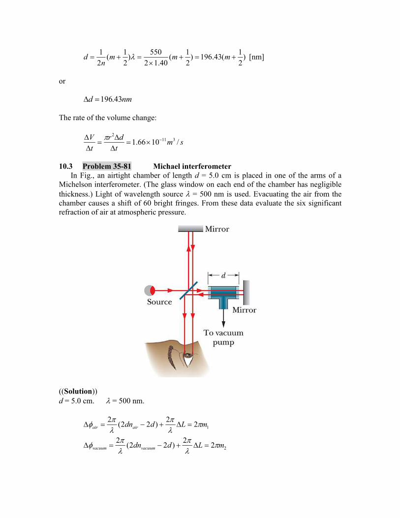
10.3 Problem 35-81 Michael interferometer
In Fig., an airtight chamber of length d = 5.0 cm is placed in one of the arms of a Michelson interferometer. (The glass window on each end of the chamber has negligible thickness.) Light of wavelength source = 500 nm is used. Evacuating the air from the chamber causes a shift of 60 bright fringes. From these data evaluate the six significant refraction of air at atmospheric pressure.
((Solution)) d = 5.0 cm. = 500 nm.
2
1
22
)22(2
22
)22(2
mLddn
mLddn
vacuumvacuum
airair
where L is the geometrical path difference between two rays, and m1 and m2 are positive integers. Then we have
)(2)(22
21 mmnnd vacuumairvacuumair
Since nvacuum = 1, we have
dmmnair 2
)(1 21
or
00030.1100.312
601 4
dnair
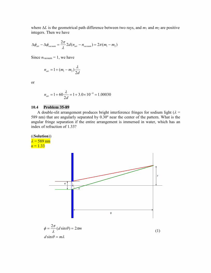
10.4 Problem 35-89
A double-slit arrangement produces bright interference fringes for sodium light ( = 589 nm) that are angularly separated by 0.30º near the center of the pattern. What is the angular fringe separation if the entire arrangement is immersed in water, which has an index of refraction of 1.33? ((Solution)) = 589 nm n = 1.33
md
md
sin
2)sin(2
(1)
''sin
'2)'sin(2
mnd
mndn
(2)
From Eq.(1),
md
md
cos
where cos ≈ 1. From Eq,(2)
''
'''cos
mnd
mnd
where cos’≈ 1. Then we have
30.0d
md
for m = 1.
23.033.1
130.0''
ndm
nd
for m’ = 1. APPENDIX: Josephson junction and DC SQUID
A1. Introduction
For superconducting tunnel junctions with extremely thin insulating layers (10 – 15 Å) (weak link between the superconductors), the electron pair correlations extend through the insulating barrier. In this situation, it has been predicted by Josephson that paired electrons (Cooper pairs) can tunnel without dissipation from one superconductor to the other superconductor on the opposite side of the insulating layer [B.D. Josephson, Phys. Lett. 1, 251 (1962). The direct supercurrent of pairs, for currents less that Ic, flows with zero voltage drop across the junction (DC Josephson effect). The width of the insulating barrier of the junction limits the maximum that can flow across the junction, but introduce no resistance in the flow. Josephson also predicted that in the case a constant finite voltage V is established across the junction, an alternating supercurrent Ic sin(Jt+0) flows with frequency J = 2eV/ħ (AC Josephson effect

Tunneling if Cooper pairs form a superconductor through a layer of insulator into another superconductor. Such a junction is called a weak link. (i) DC Josephson effect
A DC current flows across the junction in the absence of any electric or magnetic field.
(ii) AC Josephson effect A DC voltage applied across the junction causes rf (radio frequency) current oscillation across the junction.
(iii) Macroscopic long range quantum interference A DC magnetic field applied through a superconducting circuit containing two junctions causes the maximum supercurrent to show interference effects as a function of magnetic field intensity.
((Brian D. Josephson))
Josephson, Pippard’s graduate student at Cambridge, attending Philip Anderson’s
lectures there in 1961 to 1962, became fascinated by the concept of the pgase of the BCS-
GL order parameter as a manifestation of the quantum theory on a macroscopic scale.
Playing with the theory of Giaver tunneling, Josephson found a phase-dependent term in
the current; he then worked out all the consequences in a series of papers, private letters,
and a privately circulated fellowship thesis. In particular, Jpsephson predicted that a direct
current should flow, without any applied voltage, between two superconductors separated
by a thin insulating layer. This current would come as a cones quence of the
tunneling of electron pairs between the superconductors, and the current would be
proportional to the sine of the phase difference between the superconductors. At a finite
applied voltage V, an alternating supercurrent of frequency 2eV/h should flow between the
superconductors. Josephson’s work established the phase as a fundamental variable in
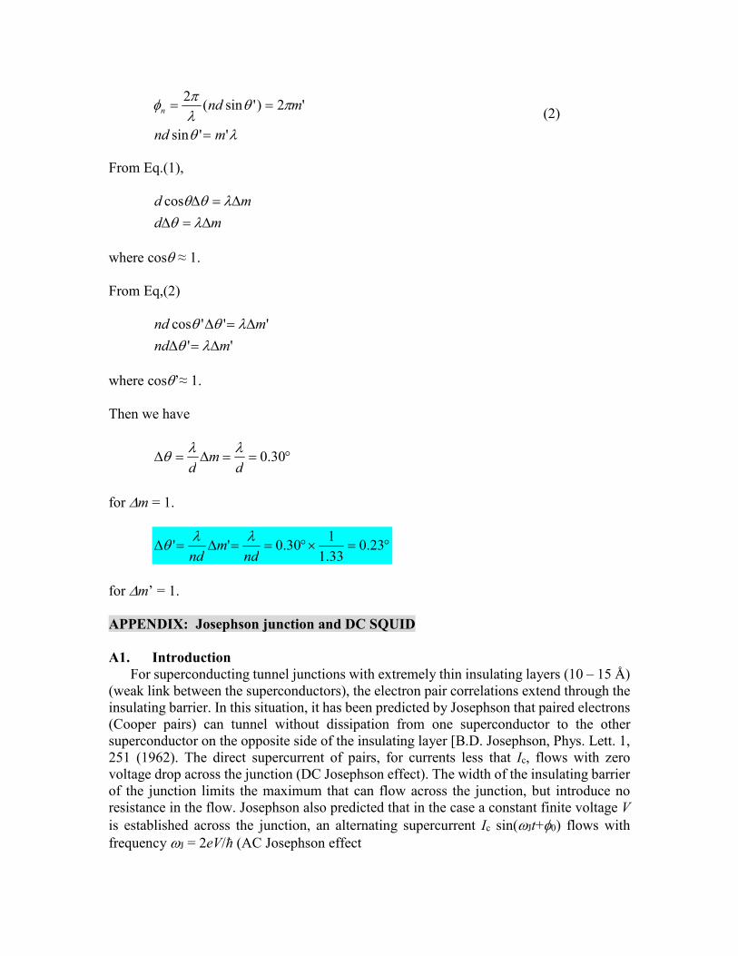
superconductivity.(Book edited by Hoddeson et al.12). A2. DC Josephson junction3
Fig.1 Schematic diagram for experiment of DC Josephson effect. Two superconductors SI and SII (the same metals) are separated by a very thin insulating layer (denoted by green). A DC Josphson supercurrent (up to a maximum value Ic) flows without dissipation through the insulating layer.
A3. SQUID (superconducting quantum interference device)3
A.3.1 Current density and flux quantization
In quantum mechanics, the current density is defined as
22* *[ ]
2
mi mc
J A
ℏ,
where q (=-2e, e>0) is a charge for electron pairs, m is a mass, A is a vector potential, and is a wavefunction. When the wavefunction is given by the amplitude |(r)|and the phase (r) as
( )( ) ie rr ,
then J can be rewritten as
2( )
q q
m c J Aℏ
ℏ.
Note that this current density is invariant under the gauge transformation. AA'
and ℏcq /' ,
2 2 2
' ( ' ') ( ' ') ( )q q q q q q
m c m c m c J A A Aℏ ℏ ℏ
ℏ ℏ ℏ,
Where / [ ( ) / ]'( ) ( ) ( )iq c i q ce e rr r r
ℏ ℏ .
If we consider now a cylinder which may become superconductor in an external magnetic field and if we take a path from a surface at a distance which is larger than the penetration depth , then J = 0. When q = -2e, we have
22 2( ) 0
e e
m c J Aℏ
ℏ,
or
2e
c A
ℏ,

0
2 2 2 22
e e e ed d d d
c c c c
l A l A a B aℏ ℏ ℏ ℏ
� � � � ,
where is the magnetic flux inside the ring and )2/(20 ecℏ (=2.06783372 x 10⁻⁷
Gauss cm2) is a quantum fluxoid. In the last equation we apply the Stoke’s theorem. ((Note))
The current flows along the ring. However, this current flows only on the surface boundary (region from the surface to the penetration depth ). Inside of the system (region far from the surface boundary), there is no current since 4 / c H J and H = 0.
A.3.2 DC SQUID (double junctions): quantum mechanics
DC SQUID consists of two points contacts in parallel, forming a ring. Each contact forms a Josephson junctions of superconductor 1, insulating layer, and superconductor 2 (S1-I-S2). Suppose that a magnetic flux passes through the interior of the loop.
Fig. Schematic diagram of DC SQUID (superconducting quantum interference device).
1 and 2 refer to two point-contact weak links. The rest of the circuit is strongly superconducting.
Here we have
2 1 1 2a a b bd l� .
or
0
2112 2
bbaa
or
0
21 2
where )( 111 ab is the phase difference between the superconductors a and b through
the junction 1 and )( 222 ab are is the phase difference between the superconductors
a and b through the junction 2. When B = 0 (or = 0), we have 021 . In general, we put the form
c
e
ℏ01 ,
c
e
ℏ02 .
The total current is given by
)cos()sin(2
)]sin()[sin(
)]sin()[sin(
0
00
2121
c
eI
c
e
c
eI
IIII
c
c
c
ℏ
ℏℏ
or
)cos()sin(20
0
cII .
The current varies with and has a maximum of 2Ic when sc
e
ℏ (s: integers),
or
sse
hcs
e
c02
ℏ
.
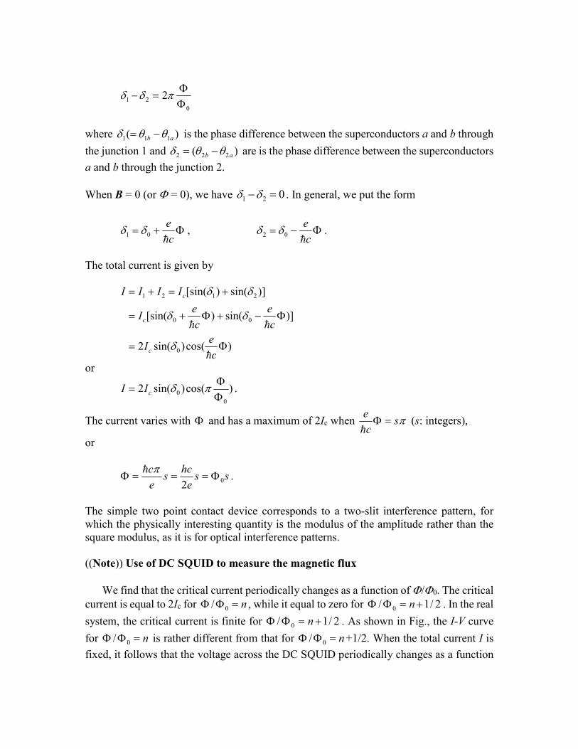
The simple two point contact device corresponds to a two-slit interference pattern, for which the physically interesting quantity is the modulus of the amplitude rather than the square modulus, as it is for optical interference patterns. ((Note)) Use of DC SQUID to measure the magnetic flux
We find that the critical current periodically changes as a function of /0. The critical current is equal to 2Ic for n 0/ , while it equal to zero for 2/1/ 0 n . In the real
system, the critical current is finite for 2/1/ 0 n . As shown in Fig., the I-V curve
for n 0/ is rather different from that for n 0/ +1/2. When the total current I is
fixed, it follows that the voltage across the DC SQUID periodically changes as a function
of 0/ . Using this principle, the value of can be exactly determined by n0 within
the error of n = ±1, where n is an integer.
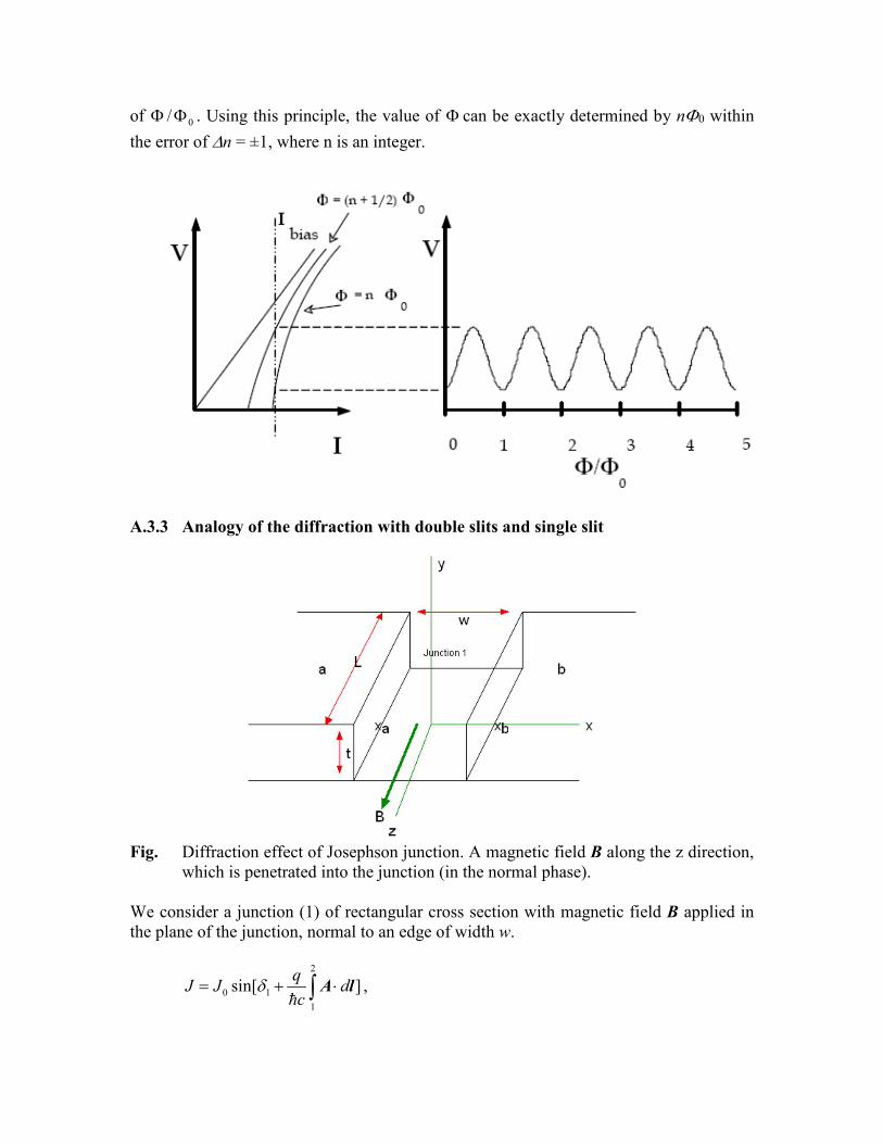
A.3.3 Analogy of the diffraction with double slits and single slit
Fig. Diffraction effect of Josephson junction. A magnetic field B along the z direction,
which is penetrated into the junction (in the normal phase). We consider a junction (1) of rectangular cross section with magnetic field B applied in the plane of the junction, normal to an edge of width w.
2
0 1
1
sin[ ]q
J J dc
A lℏ
,

weith q = -2e. We use the vector potential A given by 1
( ) ( , ,0)2 2 2
By Bx A B r , ' ( , 0, 0)By A A
Where
2
Bxy .
Then we have
]sin[])(sin[ 1010 yWc
qBJdxBy
c
qJJ
b
a
x
xℏℏ
,
dyyWc
qBLJJLdydI ]sin[ 101
ℏ ,
or
2/
2/
101 ]sin[t
t
dyyWc
qBLJI
ℏ .
Then we have
)2
sin()sin(2
101 Wt
c
qB
BWq
cLJI
ℏ
ℏ .
Here we introduce the total magnetic flux passing through the area Wt ( BWtW ),
LtJIc 0 , and
c
eBWt
e
c
BWtW
ℏℏ
2
20
, or c
eBWtW
ℏ
0
.
Therefore we have
0
011
)sin(
)sin(W
W
cII
.
The total current is given by
0
01111
)sin(
)]sin()[sin(W
W
cIIII
,
or
0
0
0
011
)sin(
)cos()sin(2W
W
cIIII
.
The short period variation is produced by interference from the two Josephson junctions, while the long period variation is a diffraction effect and arises from the finite dimensions of each junction. The interference pattern of |I|2 is very similar to the intensity of the Young’s double slits experiment. If the slits have finite width, the intensity must be multiplied by the diffraction pattern of a single slit, and for large angles the oscillations die out. A.4 Application of SQUID

B. Geometry for the phasor diagram


![[SUZUKI] Manual de Taller Suzuki Gran Vitara](https://static.fdocuments.us/doc/165x107/56d6bceb1a28ab30168bfdfc/suzuki-manual-de-taller-suzuki-gran-vitara.jpg)