Chapter 31: Faraday’s Law! Faraday’s Law of Inductionfaculty.polytechnic.org/physics/3 A.P....
12
The Beginning of the End 1.) Chapter 31: Faraday’s Law! So far, we’ve looked at: • Electric Fields for stationary charges • Magnetic fields of moving charges E = k • dq r 2 ! " E • dA = q in # o ! Now we turn to the electric field caused by a changing magnetic field. B • d! = μ o I ! 2.) One example of Faraday’s Law of Induction One simple experiment demonstrate that a current is produced by a changing magnetic field (naked coil in B-fld attached to galvanometer). 3.) Faraday’s Law of Induction The emf induced in a circuit is directly proportional to the time rate of change of magnetic flux through the circuit. ! = "d# B dt where # B = ! B•d ! A $ If we want to induce a flow of current, we need to change the magnetic flux, which we can do by changing B, A, N or A B ! ! = "d dt N ( BA cos# ) ! !. 4.)
Transcript of Chapter 31: Faraday’s Law! Faraday’s Law of Inductionfaculty.polytechnic.org/physics/3 A.P....
The Beginning of the End
1.)
Chapter 31: Faraday’s Law! So far, we’ve looked at:!• Electric Fields for stationary charges!
• Magnetic fields of moving charges!
E = k • dqr2! " E • dA = qin
#o!
Now we turn to the electric field caused by a changing magnetic field.!
B • d! = µoI!
2.)
One example of Faraday’s Law of Induction
One simple experiment demonstrate that a current is produced by a changing magnetic field (naked coil in B-fld attached to galvanometer).!
3.)
Faraday’s Law of Induction The emf induced in a circuit is directly proportional to the time rate of change of magnetic flux through the circuit.!
! ="d#B
dt
where #B =!B • d
!A$
If we want to induce a flow of current, we need to change the magnetic flux, which we can do by changing B, A, N or !
A
B
!
! = "ddtN(BAcos#)
!
!.
4.)
Example A coil is wrapped with 200 turns of wire on the perimeter of a square frame of sides 18cm. The total resistance of the coil is 2.0 ohms. A uniform magnetic field is turned on perpendicular to the plane of the coil.! a.) If the field changes linearly from 0 to 0.50Wb/m2 in a time of 0.80s, find the magnitude of the induced emf in the coil while the field is changing.! b.) What is magnitude of the current induced in the coil while the field is changing.!
a. A=0.0324 m2 , emf=4.1V b. 2.05A
5.)
Real Life Apps
AC current Sensing coil(to circuitbreaker)
Ground Fault Interrupter"If more current is coming out then going back in, flux changes, inducing an emf which triggers the circuit breaker.!
6.)
Real Life Apps
Permanentmagnet
Vibrating guitar string (w/ magnetized portion shown)
to Amplifier
Vibrating string produces a change in magnetic flux in the coil, which is transmitted as an emf to the amplifier.!
7.)
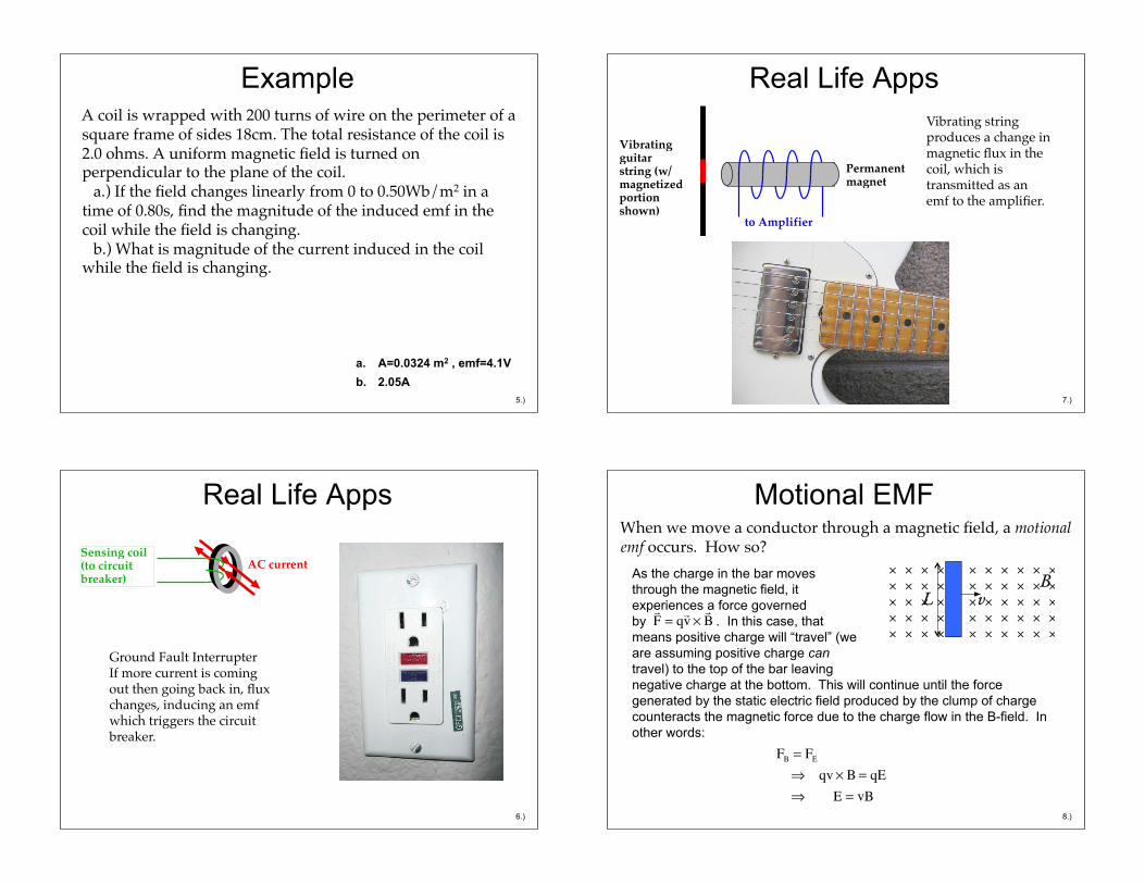
As the charge in the bar moves through the magnetic field, it experiences a force governed by . In this case, that means positive charge will “travel” (we are assuming positive charge can travel) to the top of the bar leaving
Motional EMF When we move a conductor through a magnetic field, a motional emf occurs. How so? !
!F = q!v !
!B
BL v
FB = FE
! qv " B = qE ! E = vB
negative charge at the bottom. This will continue until the force generated by the static electric field produced by the clump of charge counteracts the magnetic force due to the charge flow in the B-field. In other words:
8.)
As voltages are associated with potential energy functions, and as potential energy functions are associated with conservative force fields, and as static electric fields produce conservative forces fields, we can write the electrical potential difference between the top and bottom of the rod as:
BL v
!V = "!E •!d
= " E L cos180o
= " Bv( )L "1( ) = BLv
+
!
Note: This analysis is associated with charge in motion in a magnetic field. The voltage we’ve identified is induced by the motion. It is not an induced EMF in the “Faraday’s Law” sense (that is, there is no change in flux going on here.
9.)
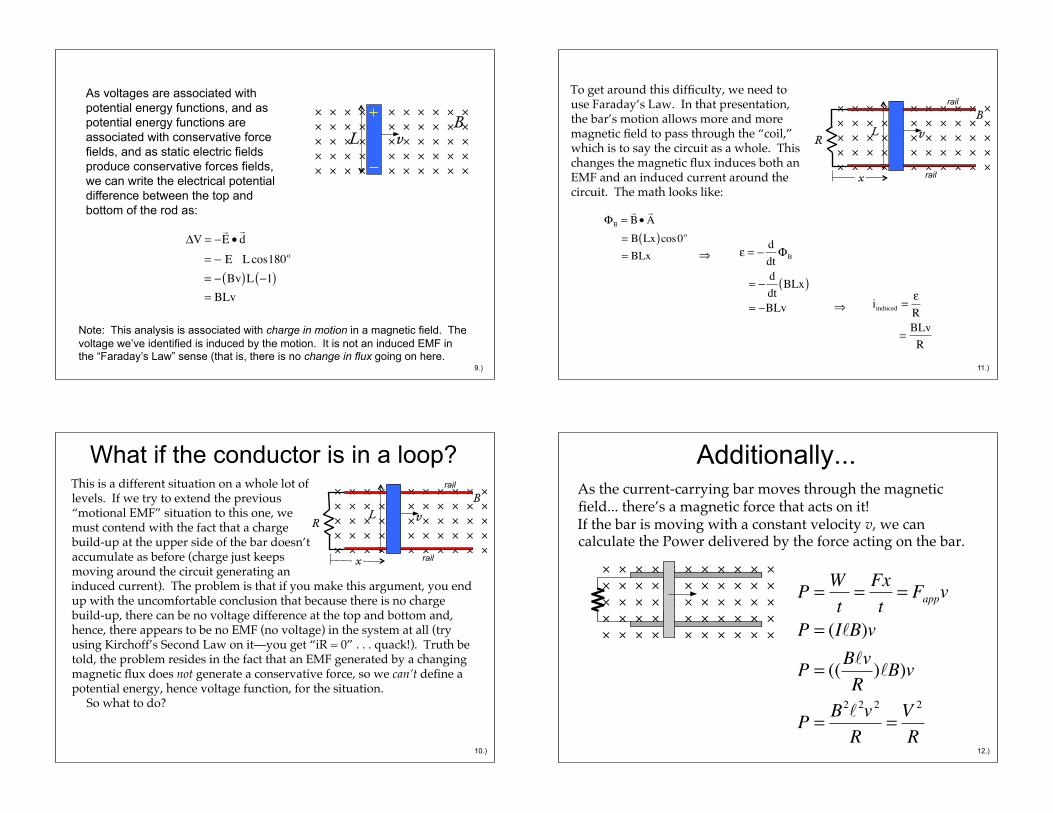
What if the conductor is in a loop? This is a different situation on a whole lot of levels. If we try to extend the previous “motional EMF” situation to this one, we must contend with the fact that a charge build-up at the upper side of the bar doesn’t accumulate as before (charge just keeps moving around the circuit generating an!
B L v
induced current). The problem is that if you make this argument, you end up with the uncomfortable conclusion that because there is no charge build-up, there can be no voltage difference at the top and bottom and, hence, there appears to be no EMF (no voltage) in the system at all (try using Kirchoff’s Second Law on it—you get “iR = 0” . . . quack!). Truth be told, the problem resides in the fact that an EMF generated by a changing magnetic flux does not generate a conservative force, so we can’t define a potential energy, hence voltage function, for the situation. ! So what to do?!
R
rail
rail
x
10.)
To get around this difficulty, we need to use Faraday’s Law. In that presentation, the bar’s motion allows more and more magnetic field to pass through the “coil,” which is to say the circuit as a whole. This changes the magnetic flux induces both an EMF and an induced current around the circuit. The math looks like:!
! = "ddt#B
= "ddt
BLx( ) = "BLv
B L vR
rail
rail
x
!B =!B•!A
= B Lx( )cos0o
= BLx
iinduced =!R
= BLvR
!
!
11.)
Additionally... As the current-carrying bar moves through the magnetic field... there’s a magnetic force that acts on it! !If the bar is moving with a constant velocity v, we can calculate the Power delivered by the force acting on the bar.!
P = Wt
= Fxt
= Fappv
P = (I!B)v
P = ((B!vR)!B)v
P = B2!2v 2
R= V
2
R12.)
Cool Problem An airplane flies from LA to Seattle, and due to its motion through the Earth’s magnetic field, undergoes motional emf. Which wingtip is positively charged: the left or the right?!
13.)
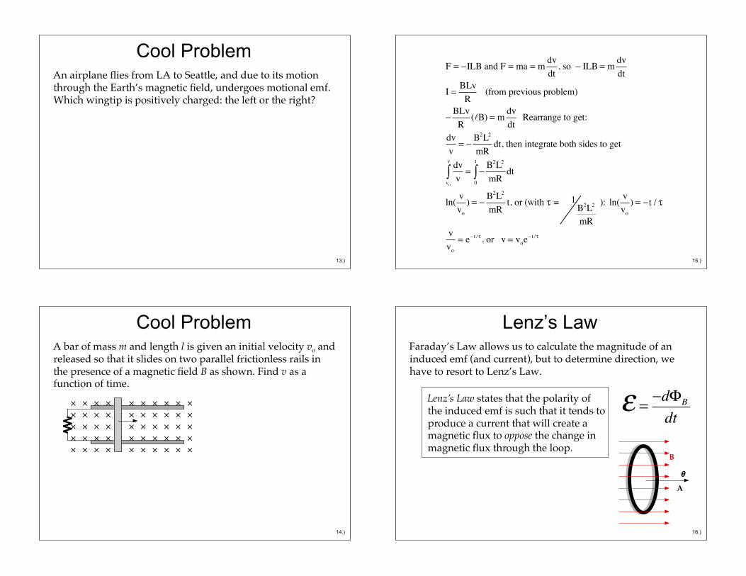
Cool Problem A bar of mass m and length l is given an initial velocity vo and released so that it slides on two parallel frictionless rails in the presence of a magnetic field B as shown. Find v as a function of time.!
14.)
F = !ILB and F = ma = m dvdt
, so ! ILB = m dvdt
I = BLvR
(from previous problem)
!BLv
R(!B) = m dv
dt Rearrange to get:
dvv
= !B2L2
mRdt, then integrate both sides to get
dvvvo
v
" = !B2L2
mRdt
0
t
"
ln( vvo
) = !B2L2
mRt, or (with # = 1
B2L2
mR
): ln( vvo
) = !t / #
vvo
= e! t /# , or v = voe! t /#
15.)
Lenz’s Law Faraday’s Law allows us to calculate the magnitude of an induced emf (and current), but to determine direction, we have to resort to Lenz’s Law.!
Lenz’s Law states that the polarity of the induced emf is such that it tends to produce a current that will create a magnetic flux to oppose the change in magnetic flux through the loop.!
! = "d#B
dt
A
B
!
16.)
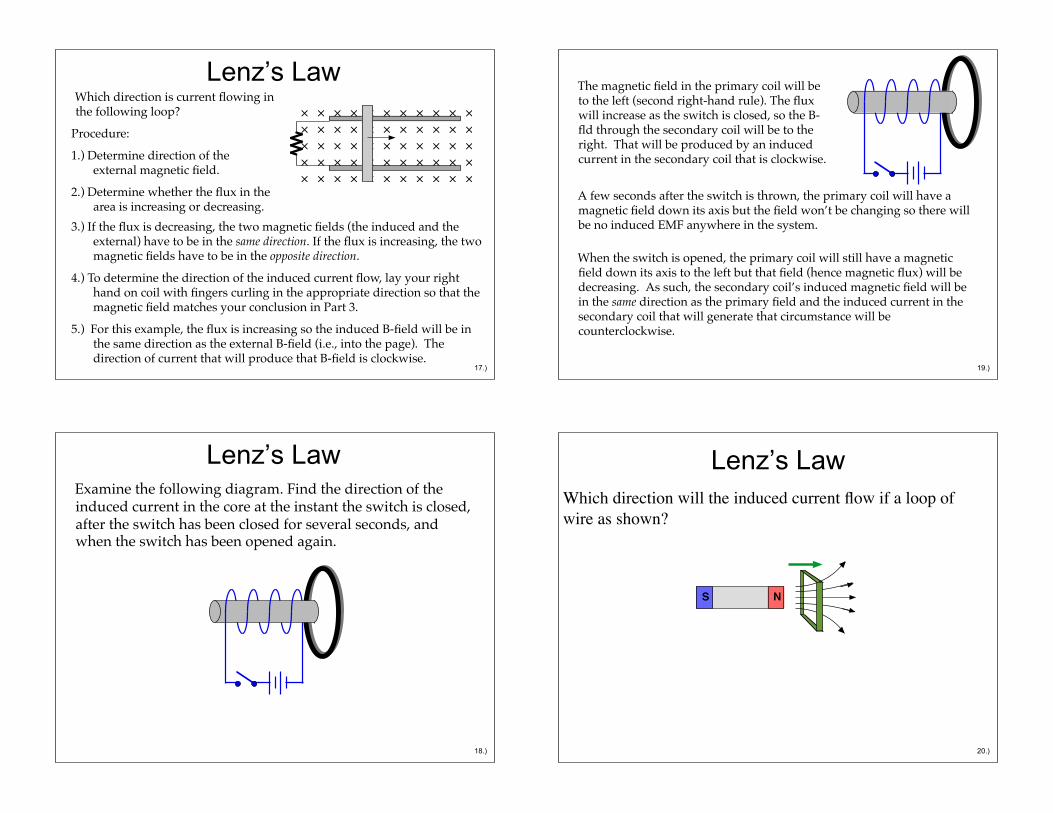
Lenz’s Law Which direction is current flowing in the following loop?!
Procedure:!1.) Determine direction of the
external magnetic field.!2.) Determine whether the flux in the
area is increasing or decreasing.!3.) If the flux is decreasing, the two magnetic fields (the induced and the
external) have to be in the same direction. If the flux is increasing, the two magnetic fields have to be in the opposite direction. !
4.) To determine the direction of the induced current flow, lay your right hand on coil with fingers curling in the appropriate direction so that the magnetic field matches your conclusion in Part 3.!
5.) For this example, the flux is increasing so the induced B-field will be in the same direction as the external B-field (i.e., into the page). The direction of current that will produce that B-field is clockwise. !
17.)
Lenz’s Law Examine the following diagram. Find the direction of the induced current in the core at the instant the switch is closed, after the switch has been closed for several seconds, and when the switch has been opened again.!
18.)
The magnetic field in the primary coil will be to the left (second right-hand rule). The flux will increase as the switch is closed, so the B-fld through the secondary coil will be to the right. That will be produced by an induced current in the secondary coil that is clockwise. !
19.)
A few seconds after the switch is thrown, the primary coil will have a magnetic field down its axis but the field won’t be changing so there will be no induced EMF anywhere in the system.!
When the switch is opened, the primary coil will still have a magnetic field down its axis to the left but that field (hence magnetic flux) will be decreasing. As such, the secondary coil’s induced magnetic field will be in the same direction as the primary field and the induced current in the secondary coil that will generate that circumstance will be counterclockwise. !
Lenz’s Law Which direction will the induced current flow if a loop of wire as shown?!
NS
20.)
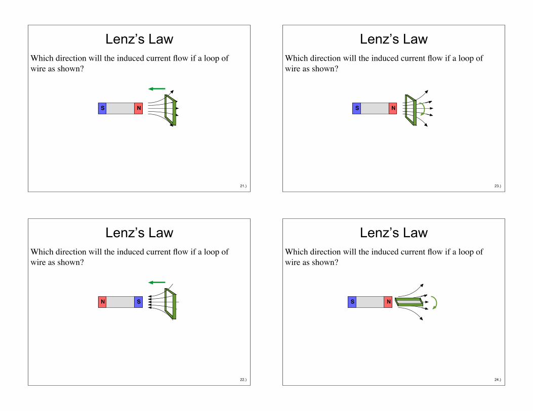
Lenz’s Law Which direction will the induced current flow if a loop of wire as shown?!
NS
21.)
Lenz’s Law Which direction will the induced current flow if a loop of wire as shown?!
N S
22.)
Lenz’s Law Which direction will the induced current flow if a loop of wire as shown?!
NS
23.)
Lenz’s Law Which direction will the induced current flow if a loop of wire as shown?!
NS
24.)
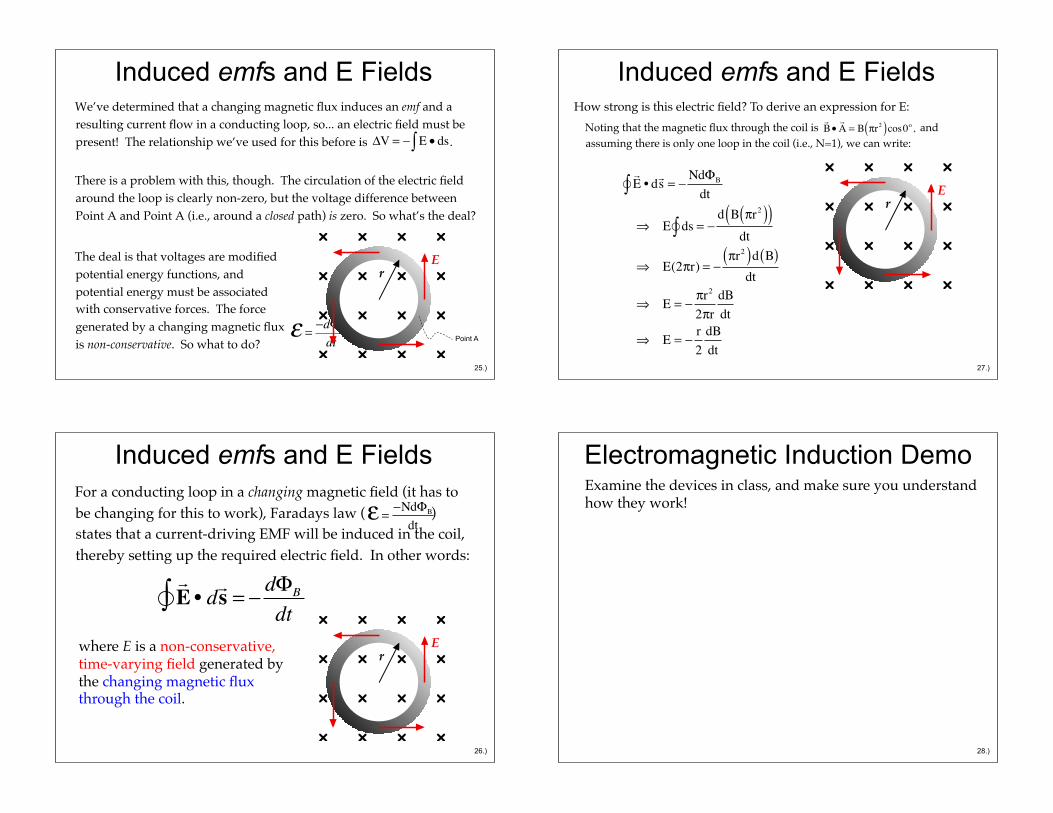
Induced emfs and E Fields We’ve determined that a changing magnetic flux induces an emf and a resulting current flow in a conducting loop, so... an electric field must be present! The relationship we’ve used for this before is .!
There is a problem with this, though. The circulation of the electric field around the loop is clearly non-zero, but the voltage difference between Point A and Point A (i.e., around a closed path) is zero. So what’s the deal? !
! = "d#B
dt
E r
!V = " E • ds#
The deal is that voltages are modified potential energy functions, and potential energy must be associated with conservative forces. The force generated by a changing magnetic flux is non-conservative. So what to do?! Point A
25.)
Induced emfs and E Fields For a conducting loop in a changing magnetic field (it has to be changing for this to work), Faradays law ( ) states that a current-driving EMF will be induced in the coil, thereby setting up the required electric field. In other words:!
! ="Nd#B
dt
E r
! E • d! s = ! d"B
dt#where E is a non-conservative, time-varying field generated by the changing magnetic flux through the coil. !
26.)
Induced emfs and E Fields
E r
How strong is this electric field? To derive an expression for E:!
!E • d!s = !
Nd"B
dt"#
$ E ds"# = !d B %r2( )( )
dt
$ E(2%r) = !%r2( )d B( )
dt
$ E = !%r2
2%rdBdt
$ E = !r2
dBdt
Noting that the magnetic flux through the coil is and assuming there is only one loop in the coil (i.e., N=1), we can write: !
!B•!A = B !r2( )cos0o,
27.)
Electromagnetic Induction Demo Examine the devices in class, and make sure you understand how they work!!
28.)
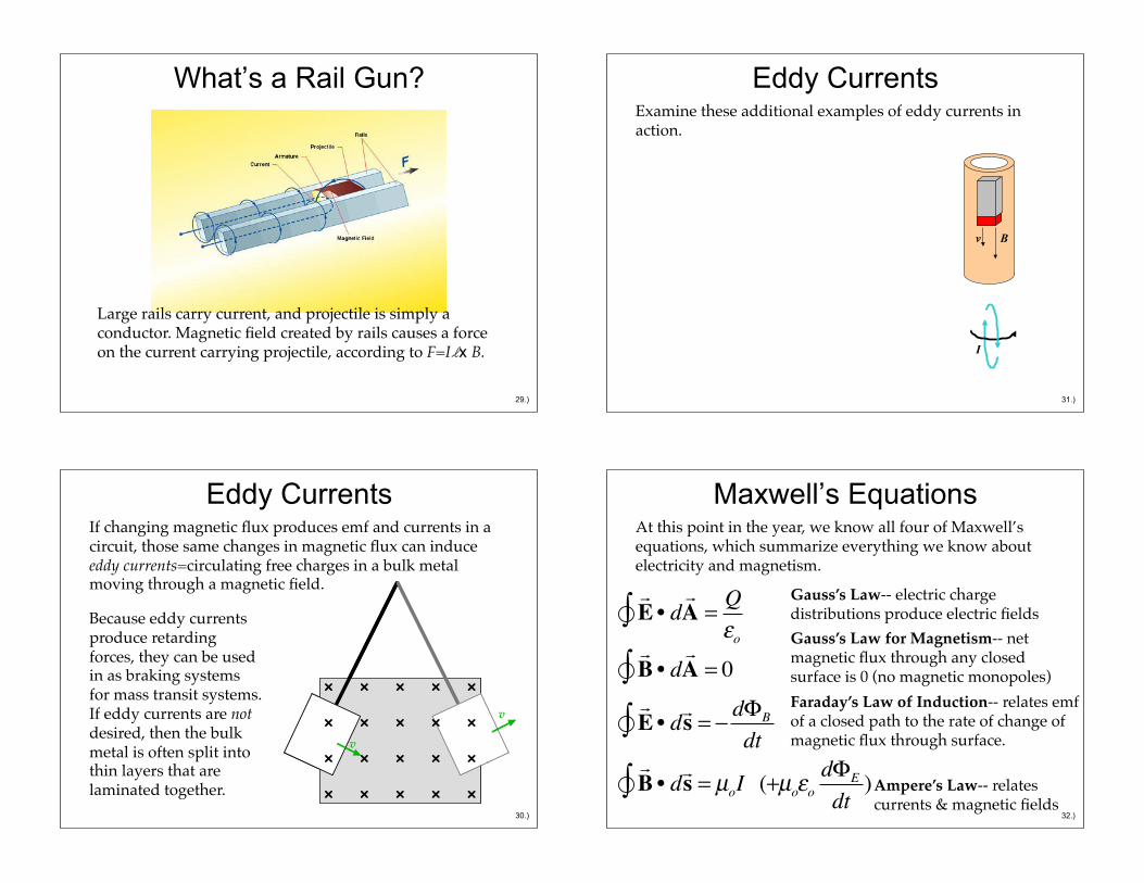
What’s a Rail Gun?
Large rails carry current, and projectile is simply a conductor. Magnetic field created by rails causes a force on the current carrying projectile, according to F=Ilx B.!
29.)
Eddy Currents If changing magnetic flux produces emf and currents in a circuit, those same changes in magnetic flux can induce eddy currents=circulating free charges in a bulk metal moving through a magnetic field.!
v v
v
Because eddy currents produce retarding forces, they can be used in as braking systems for mass transit systems. If eddy currents are not desired, then the bulk metal is often split into thin layers that are laminated together.!
30.)
Eddy Currents Examine these additional examples of eddy currents in action.!
v B
I
31.)
Maxwell’s Equations At this point in the year, we know all four of Maxwell’s equations, which summarize everything we know about electricity and magnetism.!
! E • d
! A = Q
!o"! B • d
! A = 0"
! E • d! s = # d$B
dt"! B • d! s = µoI (+" µo!o
d$E
dt)
Gauss’s Law-- electric charge distributions produce electric fields!Gauss’s Law for Magnetism-- net magnetic flux through any closed surface is 0 (no magnetic monopoles)!Faraday’s Law of Induction-- relates emf of a closed path to the rate of change of magnetic flux through surface.!
Ampere’s Law-- relates currents & magnetic fields!
32.)
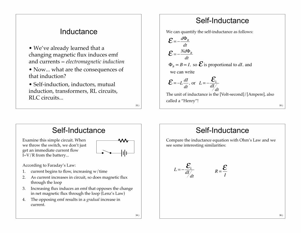
Inductance
• We’ve already learned that a changing magnetic flux induces emf and currents = electromagnetic induction!• Now... what are the consequences of that induction?!• Self-induction, inductors, mutual induction, transformers, RL circuits, RLC circuits...!
33.)
Self-Inductance Examine this simple circuit. When we throw the switch, we don’t just get an immediate current flow I=V/R from the battery...!
According to Faraday’s Law:!1. current begins to flow, increasing w/time!2. As current increases in circuit, so does magnetic flux
through the loop!3. Increasing flux induces an emf that opposes the change
in net magnetic flux through the loop (Lenz’s Law)!4. The opposing emf results in a gradual increase in
current.!
34.)
Self-Inductance We can quantify the self-inductance as follows:!
! = " d#B
dt
! = " Nd#B
dt#B $B$ I, so ! is proportional to dI, and we can write
! = "L dIdt
, or L = " !LdIdt
The unit of inductance is the [Volt-second]/[Ampere], also called a “Henry”!!
35.)
Self-Inductance Compare the inductance equation with Ohm’s Law and we see some interesting similarities:!
L = ! "L
dIdt
R =!I
36.)
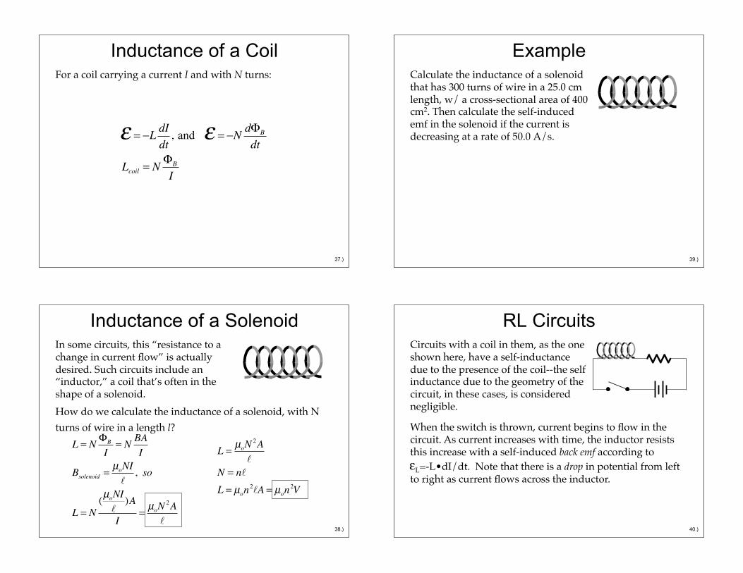
Inductance of a Coil For a coil carrying a current I and with N turns:!
! = "L dIdt
, and ! = "N d#B
dt
Lcoil = N #B
I
37.)
Inductance of a Solenoid In some circuits, this “resistance to a change in current flow” is actually desired. Such circuits include an “inductor,” a coil that’s often in the shape of a solenoid.!How do we calculate the inductance of a solenoid, with N turns of wire in a length l?!
L = N !B
I= N BA
I
Bsolenoid = µoNI!
, so
L = N(µoNI!
)A
I= µoN
2A!
L = µoN2A!
N = n!
L = µon2!A = µon
2V
38.)
Example Calculate the inductance of a solenoid that has 300 turns of wire in a 25.0 cm length, w/ a cross-sectional area of 400 cm2. Then calculate the self-induced emf in the solenoid if the current is decreasing at a rate of 50.0 A/s.!
39.)
RL Circuits Circuits with a coil in them, as the one shown here, have a self-inductance due to the presence of the coil--the self inductance due to the geometry of the circuit, in these cases, is considered negligible.!
When the switch is thrown, current begins to flow in the circuit. As current increases with time, the inductor resists this increase with a self-induced back emf according to ! L=-L•dI/dt. Note that there is a drop in potential from left to right as current flows across the inductor.!
40.)
!
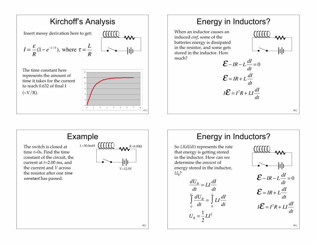
Kirchoff’s Analysis Insert messy derivation here to get:!
I = !R
(1" e" t /# ), where # = LR
The time constant here represents the amount of time it takes for the current to reach 0.632 of final I (=V/R).!
0
2
4
6
8
10
12
0 1 2 3 4 5 6 7 8
41.)
Example The switch is closed at time t=0s. Find the time constant of the circuit, the current at t=2.00 ms, and the current and V across the resistor after one time constant has passed.!
L=30.0mH
V=12.0V
R=6.00!
42.)
Energy in Inductors? When an inductor causes an induced emf, some of the batteries energy is dissipated in the resistor, and some gets stored in the inductor. How much?!
! " IR " L dIdt
= 0
! = IR + L dIdt
I! = I2R + LI dIdt
43.)
Energy in Inductors? So LI(dI/dt) represents the rate that energy is getting stored in the inductor. How can we determine the amount of energy stored in the inductor, UB?!
! " IR " L dIdt
= 0
! = IR + L dIdt
I! = I2R + LI dIdt
dUB
dt= LI dI
dtdUB
dt0
U
! = LI dIdt0
I
!
UB = 12LI2
44.)
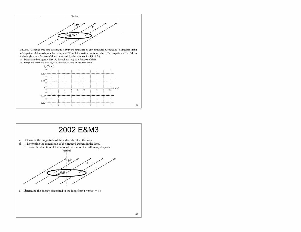
2002 E&M 3
45.)
2002 E&M3
46.)