Chapter 3 Transport Layer - School of Computing and ...users.cis.fiu.edu/~pand/tcn5030/lec06.pdf ·...
63
Transport Layer 3-1 Chapter 3 Transport Layer Computer Networking: A Top Down Approach 6 th edition Jim Kurose, Keith Ross Addison-Wesley March 2012 Slides adopted from original ones provided by the textbook authors.
Transcript of Chapter 3 Transport Layer - School of Computing and ...users.cis.fiu.edu/~pand/tcn5030/lec06.pdf ·...

Transport Layer 3-1
Chapter 3Transport Layer
Computer Networking: A Top Down Approach
6th edition Jim Kurose, Keith Ross
Addison-WesleyMarch 2012
Slides adopted from original ones provided by
the textbook authors.

Transport Layer 3-2
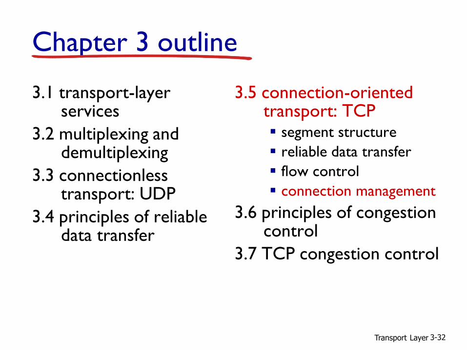
Chapter 3 outline
3.1 transport-layer services
3.2 multiplexing and demultiplexing
3.3 connectionless transport: UDP
3.4 principles of reliable data transfer
3.5 connection-oriented transport: TCP segment structure
reliable data transfer
flow control
connection management
3.6 principles of congestion control
3.7 TCP congestion control

Transport Layer 3-3
UDP: User Datagram Protocol [RFC 768]
“best effort” service, UDP segments may be:
lost
delivered out-of-order to app
connectionless:
no handshaking between UDP sender, receiver
each UDP segment handled independently of others
source port # dest port #
32 bits
applicationdata (payload)
UDP segment format
length checksum

Transport Layer 3-4
Internet checksum
1 1 1 1 0 0 1 1 0 0 1 1 0 0 1 1 01 1 1 0 1 0 1 0 1 0 1 0 1 0 1 0 1
1 1 0 1 1 1 0 1 1 1 0 1 1 1 0 1 1
1 1 0 1 1 1 0 1 1 1 0 1 1 1 1 0 01 0 1 0 0 0 1 0 0 0 1 0 0 0 0 1 1
wraparound
sum
checksum
Goal: detect “errors” (e.g., flipped bits) in transmitted segment
When adding numbers, a carryout from the most significant bit needs to be added to the result
checksum: 1s compliment of sum

Transport Layer 3-5
Chapter 3 outline
3.1 transport-layer services
3.2 multiplexing and demultiplexing
3.3 connectionless transport: UDP
3.4 principles of reliable data transfer
3.5 connection-oriented transport: TCP segment structure
reliable data transfer
flow control
connection management
3.6 principles of congestion control
3.7 TCP congestion control
Transport Layer 3-6
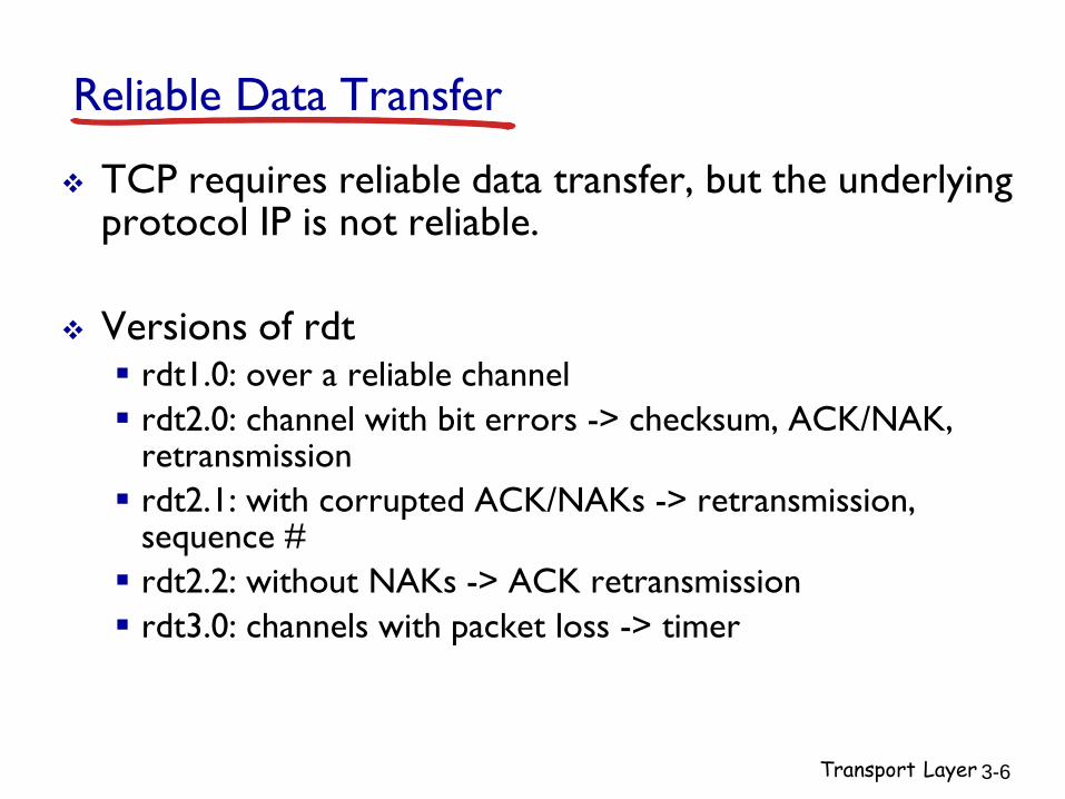
Reliable Data Transfer
TCP requires reliable data transfer, but the underlying protocol IP is not reliable.
Versions of rdt rdt1.0: over a reliable channel
rdt2.0: channel with bit errors -> checksum, ACK/NAK, retransmission
rdt2.1: with corrupted ACK/NAKs -> retransmission, sequence #
rdt2.2: without NAKs -> ACK retransmission
rdt3.0: channels with packet loss -> timer

Transport Layer 3-7
Pipelined protocols
increased utilization:
go-Back-N always send ACK for correctly-received pkt with highest in-
order seq #
timeout(n): retransmit pkt n and all higher seq # pkts in window
seq # size = window size + 1
selective repeat receiver individually acknowledges all correctly received pkts
timeout(n): sender only resends pkts for which ACK not received
seq # size = window size * 2
U sender =
n L / R RR RTT + L / R

Transport Layer 3-8
Chapter 3 outline
3.1 transport-layer services
3.2 multiplexing and demultiplexing
3.3 connectionless transport: UDP
3.4 principles of reliable data transfer
3.5 connection-oriented transport: TCP segment structure
reliable data transfer
flow control
connection management
3.6 principles of congestion control
3.7 TCP congestion control

Transport Layer 3-9
TCP: Overview RFCs: 793,1122,1323, 2018, 2581
full duplex data: bi-directional data flow
in same connection
MSS: maximum segment size
connection-oriented: handshaking (exchange
of control msgs) inits sender, receiver state before data exchange
flow controlled: sender will not
overwhelm receiver
point-to-point: one sender, one receiver
reliable, in-order byte steam: no “message
boundaries”
pipelined: TCP congestion and
flow control set window size

Transport Layer 3-10
TCP segment structure
source port # dest port #
32 bits
application
data
(variable length)
sequence number
acknowledgement number
receive window
Urg data pointerchecksum
FSRPAUhead
len
not
used
options (variable length)
URG: urgent data
(generally not used)
ACK: ACK #
valid
PSH: push data now
(generally not used)
RST, SYN, FIN:
connection estab
(setup, teardown
commands)
# bytes
rcvr willing
to accept
counting
by bytes
of data
(not segments!)
Internet
checksum
(as in UDP)
Transport Layer 3-11
Review: UDP
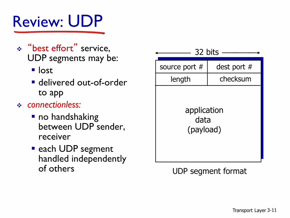
“best effort” service, UDP segments may be:
lost
delivered out-of-order to app
connectionless:
no handshaking between UDP sender, receiver
each UDP segment handled independently of others
source port # dest port #
32 bits
applicationdata
(payload)
UDP segment format
length checksum

Maximum segment size (MSS)
MSS: maximum bytes of TCP payload
Sequence #: byte-stream # of first byte in segment
E.g. file size 500,000 bytes, MSS 1,000 bytes
Transport Layer 3-12

Transport Layer 3-13
TCP seq. numbers, ACKs
sequence numbers:
byte stream “number” of first byte in segment’s data
acknowledgements:
seq # of next byte expected from other side
cumulative ACK
Q: how receiver handles out-of-order segments
A: TCP spec doesn’t say, - up to implementor source port # dest port #
sequence number
acknowledgement number
checksum
rwnd
urg pointer
incoming segment to sender
A
sent ACKed
sent, not-yet ACKed(“in-flight”)
usablebut not yet sent
not usable
window sizeN
sender sequence number space
source port # dest port #
sequence number
acknowledgement number
checksum
rwnd
urg pointer
outgoing segment from sender

Transport Layer 3-14
TCP seq. numbers, ACKs
Usertypes‘C’
host ACKsreceipt
of echoed‘C’
host ACKsreceipt of‘C’, echoesback ‘C’
simple telnet scenario
Host BHost A
Seq=42, ACK=79, data = ‘C’
Seq=79, ACK=43, data = ‘C’
Seq=43, ACK=80

Example
P26. Consider transferring an enormous file of L bytes from Host A to Host B. Assume an MSS of 536 bytes.
a. What is the maximum value of L such that TCP sequence numbers are not exhausted?
b. For the L you obtain in (a), find how long it takes to transmit the file. Assume that a total of 66 bytes of transport, network, and data-link header are added to each segment before the resulting packet is sent tout via a 155 Mbps link.
Transport Layer 3-15

Transport Layer 3-16
TCP round trip time, timeout
Q: how to set TCP timeout value?
longer than RTT
but RTT varies
too short: premature timeout, unnecessary retransmissions
too long: slow reaction to segment loss
Q: how to estimate RTT? SampleRTT: measured
time from segment transmission until ACK receipt
ignore retransmissions
SampleRTT will vary, want estimated RTT “smoother”
average several recentmeasurements, not just current SampleRTT

Transport Layer 3-17
RTT: gaia.cs.umass.edu to fantasia.eurecom.fr
100
150
200
250
300
350
1 8 15 22 29 36 43 50 57 64 71 78 85 92 99 106
time (seconnds)
RT
T (
mil
lise
con
ds)
SampleRTT Estimated RTT
EstimatedRTT = (1- )*EstimatedRTT + *SampleRTT
exponential weighted moving average influence of past sample decreases exponentially fast typical value: = 0.125
TCP round trip time, timeout
RTT (
mill
iseco
nds)
RTT: gaia.cs.umass.edu to fantasia.eurecom.fr
sampleRTT
EstimatedRTT
time (seconds)

Transport Layer 3-18
timeout interval: EstimatedRTT plus “safety margin” large variation in EstimatedRTT -> larger safety margin
estimate SampleRTT deviation from EstimatedRTT:
DevRTT = (1-)*DevRTT +
*|SampleRTT-EstimatedRTT|
TCP round trip time, timeout
(typically, = 0.25)
TimeoutInterval = EstimatedRTT + 4*DevRTT
estimated RTT “safety margin”

Transport Layer 3-19
Chapter 3 outline
3.1 transport-layer services
3.2 multiplexing and demultiplexing
3.3 connectionless transport: UDP
3.4 principles of reliable data transfer
3.5 connection-oriented transport: TCP segment structure
reliable data transfer
flow control
connection management
3.6 principles of congestion control
3.7 TCP congestion control

Transport Layer 3-20
TCP reliable data transfer
TCP creates rdt service on top of IP’s unreliable service pipelined segments
cumulative acks
single retransmission timer
retransmissions triggered by: timeout events
duplicate acks
let’s initially consider simplified TCP sender: ignore duplicate acks
ignore flow control, congestion control

Transport Layer 3-21
TCP sender events:
data rcvd from app:
create segment with seq #
seq # is byte-stream number of first data byte in segment
start timer if not already running think of timer as for
oldest unackedsegment
expiration interval: TimeOutInterval
timeout:
retransmit segment that caused timeout
restart timer
ack rcvd:
if ack acknowledges previously unacked segments update what is known
to be ACKed
start timer if there are still unacked segments

Transport Layer 3-22
TCP sender (simplified)
wait
for
event
NextSeqNum = InitialSeqNum
SendBase = InitialSeqNum
L
create segment, seq. #: NextSeqNum
pass segment to IP (i.e., “send”)
NextSeqNum = NextSeqNum + length(data)
if (timer currently not running)
start timer
data received from application above
retransmit not-yet-acked segment with smallest seq. #
start timer
timeout
if (y > SendBase) {
SendBase = y
/* SendBase–1: last cumulatively ACKed byte */
if (there are currently not-yet-acked segments)
start timer
else stop timer
}
ACK received, with ACK field value y

Transport Layer 3-23
TCP: retransmission scenarios
lost ACK scenario
Host BHost A
Seq=92, 8 bytes of data
ACK=100
Seq=92, 8 bytes of data
Xtim
eout
ACK=100
premature timeout
Host BHost A
Seq=92, 8 bytes of data
ACK=100
Seq=92, 8bytes of data
tim
eout
ACK=120
Seq=100, 20 bytes of data
ACK=120
SendBase=100
SendBase=120
SendBase=120
SendBase=92

Transport Layer 3-24
TCP: retransmission scenarios
X
cumulative ACK
Host BHost A
Seq=92, 8 bytes of data
ACK=100
Seq=120, 15 bytes of data
tim
eout
Seq=100, 20 bytes of data
ACK=120

Transport Layer 3-25
TCP ACK generation [RFC 1122, RFC 2581]
event at receiver
arrival of in-order segment with
expected seq #. All data up to
expected seq # already ACKed
arrival of in-order segment with
expected seq #. One other
segment has ACK pending
arrival of out-of-order segment
higher-than-expect seq. # .
Gap detected
arrival of segment that
partially or completely fills gap
TCP receiver action
delayed ACK. Wait up to 500ms
for next segment. If no next segment,
send ACK
immediately send single cumulative
ACK, ACKing both in-order segments
immediately send duplicate ACK,
indicating seq. # of next expected byte
immediate send ACK, provided that
segment starts at lower end of gap

Transport Layer 3-26
TCP fast retransmit
time-out period often relatively long: long delay before
resending lost packet
detect lost segments via duplicate ACKs. sender often sends
many segments back-to-back
if segment is lost, there will likely be many duplicate ACKs.
if sender receives 3 ACKs for same data
(“triple duplicate ACKs”),
resend unacked segment with smallest seq # likely that unacked
segment lost, so don’t wait for timeout
TCP fast retransmit
(“triple duplicate ACKs”),

Transport Layer 3-27
X
fast retransmit after sender receipt of triple duplicate ACK
Host BHost A
Seq=92, 8 bytes of data
ACK=100
tim
eout
ACK=100
ACK=100
ACK=100
TCP fast retransmit
Seq=100, 20 bytes of data
Seq=100, 20 bytes of data

Example
R15. Suppose Host A sends two TCP segments back to back to Host B over a TCP connection. The first segment has sequence number 90; the second has sequence number 100.
a. How much data is in the first segment?
b. Suppose that the first segment is lost but the second segment arrives at B. In the acknowledgement that Host B sends to Host A, what will be the acknowledgement number?
Transport Layer 3-28

Transport Layer 3-29
Chapter 3 outline
3.1 transport-layer services
3.2 multiplexing and demultiplexing
3.3 connectionless transport: UDP
3.4 principles of reliable data transfer
3.5 connection-oriented transport: TCP segment structure
reliable data transfer
flow control
connection management
3.6 principles of congestion control
3.7 TCP congestion control

Transport Layer 3-30
TCP flow controlapplication
process
TCP socketreceiver buffers
TCPcode
IPcode
application
OS
receiver protocol stack
application may remove data from
TCP socket buffers ….
… slower than TCP receiver is delivering(sender is sending)
from sender
receiver controls sender, so
sender won’t overflow
receiver’s buffer by transmitting
too much, too fast
flow control

Transport Layer 3-31
TCP flow control
buffered data
free buffer spacerwnd
RcvBuffer
TCP segment payloads
to application process
receiver “advertises” free buffer space by including rwnd value in TCP header of receiver-to-sender segments RcvBuffer size set via
socket options (typical default is 4096 bytes)
many operating systems autoadjust RcvBuffer
sender limits amount of unacked (“in-flight”) data to receiver’s rwnd value
guarantees receive buffer will not overflow
receiver-side buffering
Transport Layer 3-32
Chapter 3 outline
3.1 transport-layer services
3.2 multiplexing and demultiplexing
3.3 connectionless transport: UDP
3.4 principles of reliable data transfer
3.5 connection-oriented transport: TCP segment structure
reliable data transfer
flow control
connection management
3.6 principles of congestion control
3.7 TCP congestion control

Transport Layer 3-33
Connection Management
before exchanging data, sender/receiver “handshake”: agree to establish connection (each knowing the other willing
to establish connection)
agree on connection parameters
connection state: ESTABconnection variables:
seq # client-to-serverserver-to-client
rcvBuffer size
at server,client
application
network
connection state: ESTABconnection Variables:
seq # client-to-serverserver-to-client
rcvBuffer size
at server,client
application
network

Transport Layer 3-34
TCP 3-way handshake
SYNbit=1, Seq=x
choose init seq num, xsend TCP SYN msg
ESTAB
SYNbit=1, Seq=yACKbit=1; ACKnum=x+1
choose init seq num, ysend TCP SYNACKmsg, acking SYN
ACKbit=1, ACKnum=y+1
received SYNACK(x) indicates server is live;send ACK for SYNACK;
this segment may contain client-to-server data
received ACK(y) indicates client is live
SYNSENT
ESTAB
SYN RCVD
client state
LISTEN
server state
LISTEN

Transport Layer 3-35
TCP 3-way handshake: FSM
closed
L
listen
SYNrcvd
SYNsent
ESTAB
Socket clientSocket =
newSocket("hostname","port
number");
SYN(seq=x)
Socket connectionSocket =
welcomeSocket.accept();
SYN(x)
SYNACK(seq=y,ACKnum=x+1)create new socket for
communication back to client
SYNACK(seq=y,ACKnum=x+1)
ACK(ACKnum=y+1)ACK(ACKnum=y+1)
L

Transport Layer 3-36
TCP: closing a connection
client, server each close their side of connection send TCP segment with FIN bit = 1
respond to received FIN with ACK on receiving FIN, ACK can be combined with own FIN
simultaneous FIN exchanges can be handled

Transport Layer 3-37
FIN_WAIT_2
CLOSE_WAIT
FINbit=1, seq=y
ACKbit=1; ACKnum=y+1
ACKbit=1; ACKnum=x+1
wait for serverclose
can stillsend data
can no longersend data
LAST_ACK
CLOSED
TIMED_WAIT
timed wait for 2*max
segment lifetime
CLOSED
TCP: closing a connection
FIN_WAIT_1 FINbit=1, seq=xcan no longersend but canreceive data
clientSocket.close()
client state server state
ESTABESTAB

Transport Layer 3-38
Chapter 3 outline
3.1 transport-layer services
3.2 multiplexing and demultiplexing
3.3 connectionless transport: UDP
3.4 principles of reliable data transfer
3.5 connection-oriented transport: TCP segment structure
reliable data transfer
flow control
connection management
3.6 principles of congestion control
3.7 TCP congestion control

Transport Layer 3-39
congestion: informally: “too many sources sending too much
data too fast for network to handle” different from flow control!
manifestations:
lost packets (buffer overflow at routers)
long delays (queueing in router buffers)
a top-10 problem!
Principles of congestion control
Transport Layer 3-40
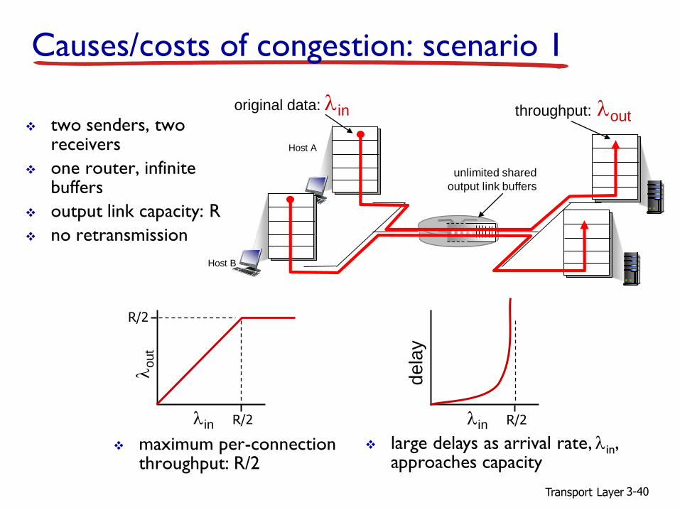
Causes/costs of congestion: scenario 1
two senders, two receivers
one router, infinite buffers
output link capacity: R
no retransmission
maximum per-connection throughput: R/2
unlimited shared
output link buffers
Host A
original data: lin
Host B
throughput: lout
R/2
R/2
lout
lin R/2dela
ylin
large delays as arrival rate, lin, approaches capacity

Transport Layer 3-41
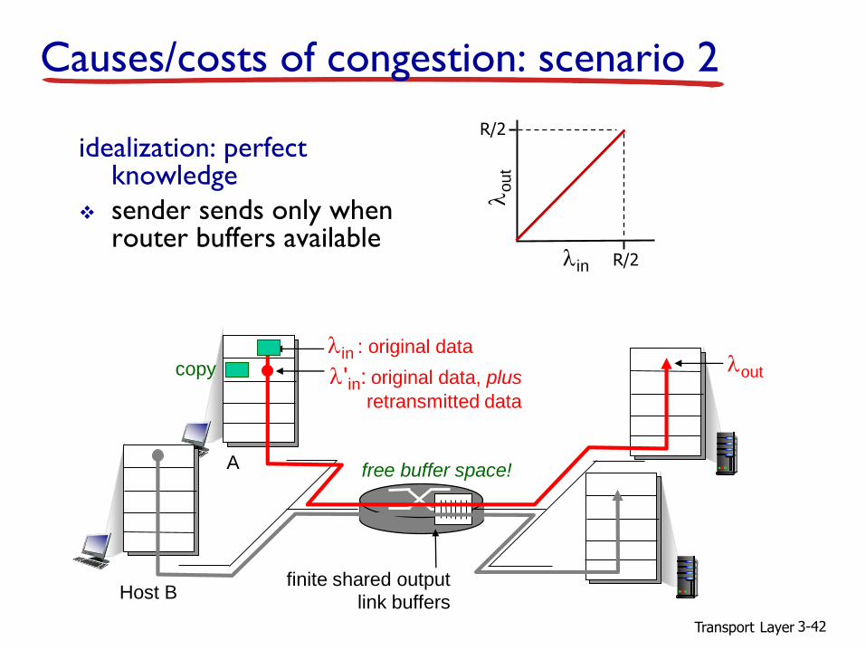
one router, finite buffers
sender retransmission of timed-out packet application-layer input = application-layer output: lin = lout
transport-layer input includes retransmissions : lin lin
finite shared output
link buffers
Host A
lin : original data
Host B
loutl'in: original data, plus
retransmitted data
‘
Causes/costs of congestion: scenario 2
Transport Layer 3-42
idealization: perfect knowledge
sender sends only when router buffers available
finite shared output
link buffers
lin : original dataloutl'in: original data, plus
retransmitted data
copy
free buffer space!
R/2
R/2
lout
lin
Causes/costs of congestion: scenario 2
Host B
A

Transport Layer 3-43
lin : original dataloutl'in: original data, plus
retransmitted data
copy
no buffer space!
Idealization: known losspackets can be lost, dropped at router due to full buffers
sender only resends if packet known to be lost
Causes/costs of congestion: scenario 2
A
Host B

Transport Layer 3-44
lin : original dataloutl'in: original data, plus
retransmitted data
free buffer space!
Causes/costs of congestion: scenario 2
Idealization: known losspackets can be lost, dropped at router due to full buffers
sender only resends if packet known to be lost
R/2
R/2lin
lo
ut
when sending at R/2,
some packets are
retransmissions but
asymptotic goodput
is still R/2 (why?)
A
Host B

Transport Layer 3-45
A
linloutl'in
copy
free buffer space!
timeout
R/2
R/2lin
lo
ut
when sending at R/2,
some packets are
retransmissions
including duplicated
that are delivered!
Host B
Realistic: duplicates packets can be lost, dropped
at router due to full buffers
sender times out prematurely, sending two copies, both of which are delivered
Causes/costs of congestion: scenario 2

Transport Layer 3-46
R/2
lo
ut
when sending at R/2,
some packets are
retransmissions
including duplicated
that are delivered!
“costs” of congestion: more work (retrans) for given “goodput” unneeded retransmissions: link carries multiple copies of pkt
decreasing goodput
R/2lin
Causes/costs of congestion: scenario 2
Realistic: duplicates packets can be lost, dropped
at router due to full buffers
sender times out prematurely, sending two copies, both of which are delivered

Transport Layer 3-47
four senders
multihop paths
timeout/retransmit
Q: what happens as lin and lin’
increase ?
finite shared output
link buffers
Host A lout
Causes/costs of congestion: scenario 3
Host B
Host C
Host D
lin : original data
l'in: original data, plus
retransmitted data
A: as red lin’ increases, all arriving
blue pkts at upper queue are dropped, blue throughput g 0

Transport Layer 3-48
another “cost” of congestion:
when packet dropped, any “upstream transmission capacity used for that packet was wasted!
Causes/costs of congestion: scenario 3
C/2
C/2
lout
lin’

Transport Layer 3-49
Approaches towards congestion control
two broad approaches towards congestion control:
end-end congestion control:
no explicit feedback from network
congestion inferred from end-system observed loss, delay
approach taken by TCP
network-assisted congestion control:
routers provide feedback to end systems
single bit indicating congestion (SNA, DECbit, TCP/IP ECN, ATM)
explicit rate for sender to send at

Transport Layer 3-50
Case study: ATM ABR congestion control
ABR: available bit rate: “elastic service”
if sender’s path “underloaded”:
sender should use available bandwidth
if sender’s path congested:
sender throttled to minimum guaranteed rate
RM (resource management) cells:
sent by sender, interspersed with data cells
bits in RM cell set by switches (“network-assisted”)
NI bit: no increase in rate (mild congestion)
CI bit: congestion indication
RM cells returned to sender by receiver, with bits intact

Transport Layer 3-51
Case study: ATM ABR congestion control
two-byte ER (explicit rate) field in RM cell congested switch may lower ER value in cell
senders’ send rate thus max supportable rate on path
EFCI bit in data cells: set to 1 in congested switch
if data cell preceding RM cell has EFCI set, receiver sets CI bit in returned RM cell
RM cell data cell

Transport Layer 3-52
Chapter 3 outline
3.1 transport-layer services
3.2 multiplexing and demultiplexing
3.3 connectionless transport: UDP
3.4 principles of reliable data transfer
3.5 connection-oriented transport: TCP segment structure
reliable data transfer
flow control
connection management
3.6 principles of congestion control
3.7 TCP congestion control

Transport Layer 3-53
TCP congestion control: additive increase multiplicative decrease
approach: sender increases transmission rate (window size), probing for usable bandwidth, until loss occurs
additive increase: increase cwnd by 1 MSS every RTT until loss detected
multiplicative decrease: cut cwnd in half after loss cwnd:
TC
P s
ender
congestion w
indow
siz
e
AIMD saw tooth
behavior: probing
for bandwidth
additively increase window size ……. until loss occurs (then cut window in half)
time

Transport Layer 3-54
TCP Congestion Control: details
sender limits transmission:
cwnd is dynamic, function of perceived network congestion
TCP sending rate:
roughly: send cwnd bytes, wait RTT for ACKS, then send more bytes
last byteACKed sent, not-
yet ACKed(“in-flight”)
last byte sent
cwnd
LastByteSent-
LastByteAcked< cwnd
sender sequence number space
rate ~~cwnd
RTTbytes/sec
Transport Layer 3-55
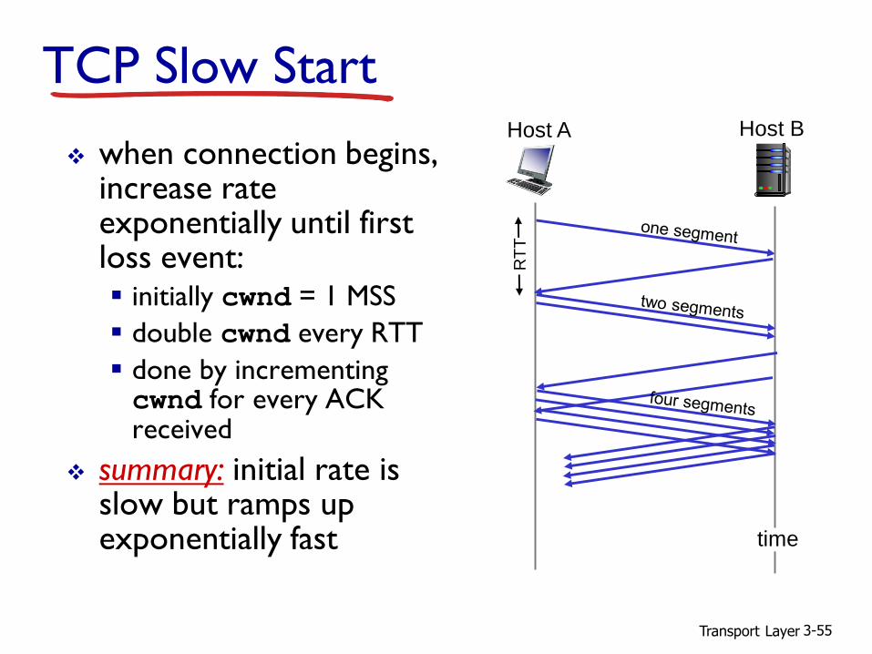
TCP Slow Start
when connection begins, increase rate exponentially until first loss event: initially cwnd = 1 MSS
double cwnd every RTT
done by incrementing cwnd for every ACK received
summary: initial rate is slow but ramps up exponentially fast
Host A
RT
T
Host B
time

Transport Layer 3-56
TCP: detecting, reacting to loss
loss indicated by timeout: cwnd set to 1 MSS;
window then grows exponentially (as in slow start) to threshold, then grows linearly
loss indicated by 3 duplicate ACKs: TCP RENO
dup ACKs indicate network capable of delivering some segments
cwnd is cut in half window then grows linearly
TCP Tahoe always sets cwnd to 1 (timeout or 3 duplicate acks)
Transport Layer 3-57
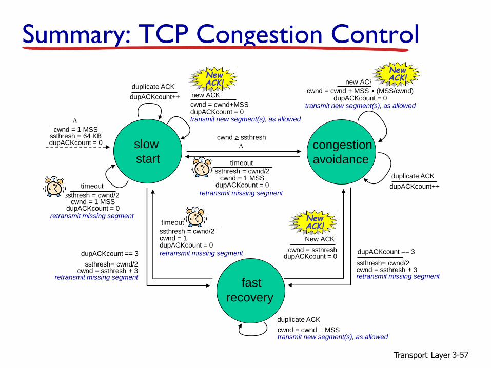
Summary: TCP Congestion Control
timeout
ssthresh = cwnd/2cwnd = 1 MSS
dupACKcount = 0retransmit missing segment
L
cwnd > ssthresh
congestion
avoidance
cwnd = cwnd + MSS (MSS/cwnd)dupACKcount = 0
transmit new segment(s), as allowed
new ACK.
dupACKcount++
duplicate ACK
fast
recovery
cwnd = cwnd + MSStransmit new segment(s), as allowed
duplicate ACK
ssthresh= cwnd/2cwnd = ssthresh + 3
retransmit missing segment
dupACKcount == 3
timeout
ssthresh = cwnd/2cwnd = 1 dupACKcount = 0retransmit missing segment
ssthresh= cwnd/2cwnd = ssthresh + 3retransmit missing segment
dupACKcount == 3cwnd = ssthreshdupACKcount = 0
New ACK
slow
start
timeout
ssthresh = cwnd/2 cwnd = 1 MSS
dupACKcount = 0retransmit missing segment
cwnd = cwnd+MSSdupACKcount = 0transmit new segment(s), as allowed
new ACKdupACKcount++
duplicate ACK
L
cwnd = 1 MSSssthresh = 64 KBdupACKcount = 0
NewACK!
NewACK!
NewACK!

Transport Layer 3-58
Q: when should the exponential increase switch to linear?
A: when cwnd gets to 1/2 of its value before timeout.
Implementation: variable ssthresh
on loss event, ssthreshis set to 1/2 of cwnd just before loss event
TCP: switching from slow start to CA

Transport Layer 3-59
TCP throughput
avg. TCP thruput as function of window size, RTT? ignore slow start, assume always data to send
W: window size (measured in bytes) where loss occurs avg. window size (# in-flight bytes) is W 3/4
avg. thruput is W 3/4 per RTT
W
W/2
avg TCP thruput = 34
WRTT
bytes/sec

Transport Layer 3-60
fairness goal: if K TCP sessions share same bottleneck link of bandwidth R, each should have average rate of R/K
TCP connection 1
bottleneck
router
capacity R
TCP Fairness
TCP connection 2

Transport Layer 3-61
Why is TCP fair?
two competing sessions: additive increase gives slope of 1, as throughout increases
multiplicative decrease decreases throughput proportionally
R
R
equal bandwidth share
Connection 1 throughput
congestion avoidance: additive increase
loss: decrease window by factor of 2
congestion avoidance: additive increaseloss: decrease window by factor of 2

Transport Layer 3-62
Fairness (more)
Fairness and UDP
multimedia apps often do not use TCP do not want rate
throttled by congestion control
instead use UDP: send audio/video at
constant rate, tolerate packet loss
Fairness, parallel TCP connections
application can open multiple parallel connections between two hosts
web browsers do this
e.g., link of rate R with 9 existing connections: new app asks for 1 TCP, gets rate
R/10
new app asks for 11 TCPs, gets R/2

Transport Layer 3-63
Chapter 3: summary
principles behind transport layer services:
multiplexing, demultiplexing
reliable data transfer
flow control
congestion control
instantiation, implementation in the Internet UDP
TCP
next:
leaving the network “edge”(application, transport layers)
into the network “core”