Chapter 3: Review of Important Networking Conceptsmagda/cs620/ch3.pdfChapter 3: Review of Important...
58
1 Chapter 3: Review of Important Networking Concepts Magda El Zarki Dept. of CS UC Irvine [email protected] http://www.ics.uci.edu/~magda
Transcript of Chapter 3: Review of Important Networking Conceptsmagda/cs620/ch3.pdfChapter 3: Review of Important...
1
Chapter 3: Review of Important Networking
Concepts Magda El Zarki
Dept. of CS
UC Irvine
http://www.ics.uci.edu/~magda
2
Networking Concepts
Protocol Architecture
Protocol Layers
Encapsulation
Network Abstractions
3
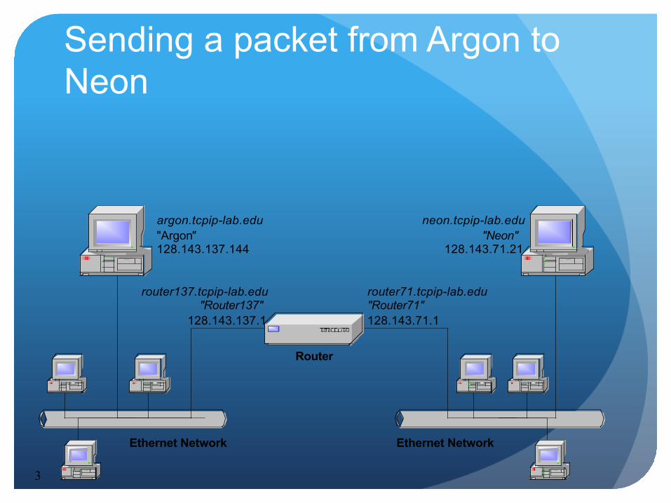
neon.tcpip-lab.edu"Neon"
128.143.71.21
argon.tcpip-lab.edu"Argon"128.143.137.144
router137.tcpip-lab.edu"Router137"
128.143.137.1
router71.tcpip-lab.edu"Router71"128.143.71.1
Ethernet NetworkEthernet Network
Router
Sending a packet from Argon to Neon
4
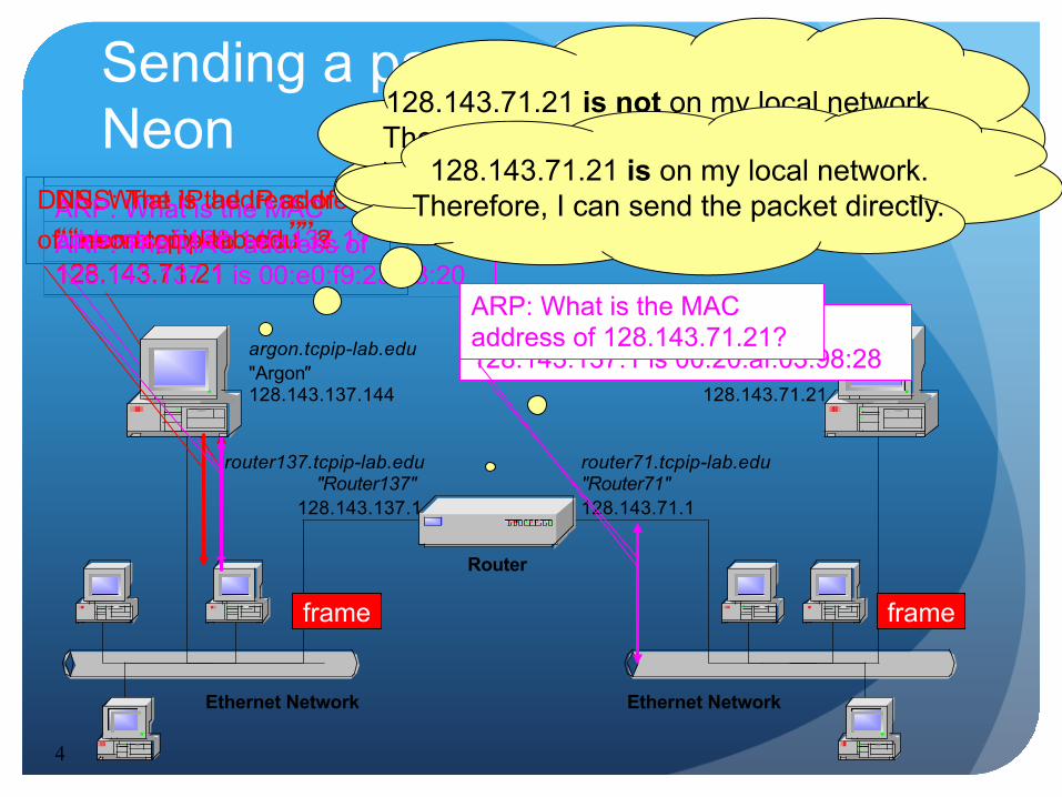
DNS: The IP address of “neon.tcpip-lab.edu” is 128.143.71.21
ARP: What is the MAC address of 128.143.137.1?
neon.tcpip-lab.edu"Neon"
128.143.71.21
argon.tcpip-lab.edu"Argon"128.143.137.144
router137.tcpip-lab.edu"Router137"
128.143.137.1
router71.tcpip-lab.edu"Router71"128.143.71.1
Ethernet NetworkEthernet Network
Router
Sending a packet from Argon to Neon
DNS: What is the IP address of “neon.tcpip-lab.edu”? ARP: The MAC address of
128.143.137.1 is 00:e0:f9:23:a8:20
128.143.71.21 is not on my local network. Therefore, I need to send the packet to my
default gateway with address 128.143.137.1
frame
128.143.71.21 is on my local network. Therefore, I can send the packet directly.
ARP: The MAC address of 128.143.137.1 is 00:20:af:03:98:28 ARP: What is the MAC address of 128.143.71.21?
frame
5
Communications Architecture
The complexity of the communication task is reduced by using multiple protocol layers:
Each protocol is implemented independently Each protocol is responsible for a specific subtask Protocols are grouped in a hierarchy
A structured set of protocols is called a communications architecture or protocol suite
6
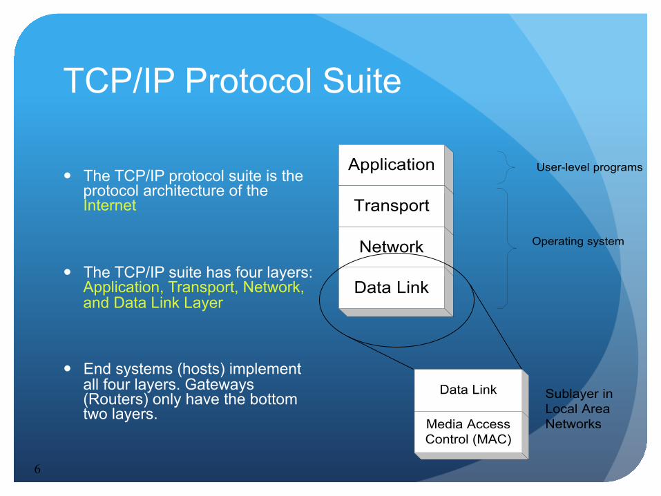
TCP/IP Protocol Suite
The TCP/IP protocol suite is the protocol architecture of the Internet
The TCP/IP suite has four layers: Application, Transport, Network, and Data Link Layer
End systems (hosts) implement all four layers. Gateways (Routers) only have the bottom two layers.
Application
Transport
Network Operating system
User-level programs
Data Link
Data Link
Media AccessControl (MAC)
Sublayer inLocal AreaNetworks

7
Functions of the Layers Data Link Layer:
Service: Reliable transfer of frames over a link Media Access Control on a LAN
Functions: Framing, media access control, error checking
Network Layer: Service: Move packets from source host to destination host Functions: Routing, addressing
Transport Layer: Service: Delivery of data between hosts Functions: Connection establishment/termination, error
control, flow control
Application Layer: Service: Application specific (delivery of email, retrieval of HTML documents, reliable transfer of file) Functions: Application specific
8
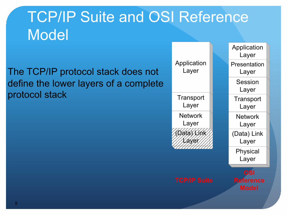
TCP/IP Suite and OSI Reference Model
ApplicationLayer
ApplicationLayer
PresentationLayer
SessionLayer
TransportLayer
NetworkLayer
(Data) LinkLayer
PhysicalLayer
TransportLayer
NetworkLayer
OSIReference
Model
(Data) LinkLayer
TCP/IP Suite
The TCP/IP protocol stack does not define the lower layers of a complete protocol stack
9
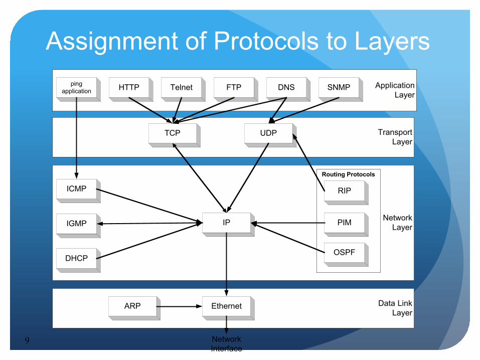
Assignment of Protocols to Layers
NetworkLayer
Routing Protocols
PIM
OSPF
RIP
ApplicationLayer
Data LinkLayer
IP
ARP Ethernet
NetworkInterface
TransportLayer
TCP UDP
SNMPFTP DNSHTTP
ICMP
IGMP
pingapplication Telnet
DHCP

10
Layered Communications
An entity of a particular layer can only communicate with: 1. a peer layer entity using a common protocol (Peer
Protocol) 2. adjacent layers to provide services and to receive
services N+1 Layer
EntityN+1 Layer
EntityN+1 Layer Protocol
N+1 Layer
N-1 LayerEntity
N-1 LayerEntity
N-1 Layer ProtocolN-1 Layer
N LayerEntity
N LayerEntity
N Layer ProtocolN Layer
layer N+1/Ninterface
layer N/N-1interface
11
Service Primitives
N+1 Layer Entity
N+1 Layer Entity
N Layer Entity
N Layer Entity
N+1 Layer Peer Protocol
Request Delivery
Indicate Delivery
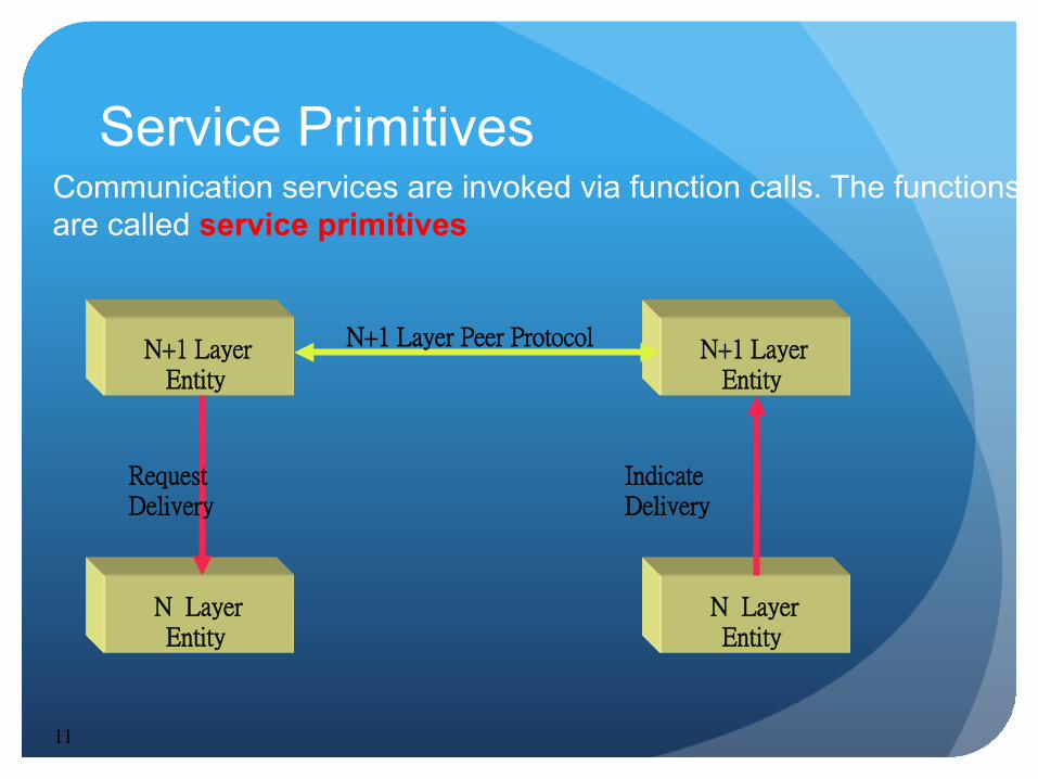
Communication services are invoked via function calls. The functions are called service primitives

12
Service Primitives Recall: A layer N+1 entity sees the lower layers only as a service provider
Service Provider
N+1 Layer Entity
N+1 Layer Entity
N+1 Layer Peer Protocol
Request Delivery
Indicate Delivery
13
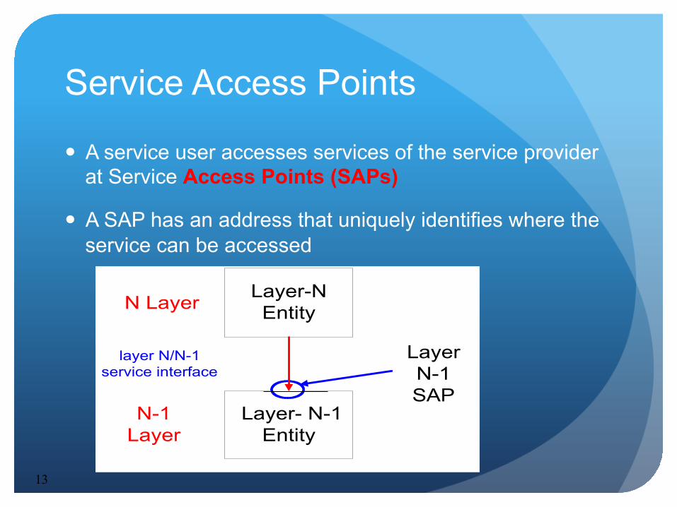
Service Access Points
A service user accesses services of the service provider at Service Access Points (SAPs)
A SAP has an address that uniquely identifies where the service can be accessed
Layer-NEntityN Layer
Layer- N-1Entity
N-1Layer
layer N/N-1service interface
LayerN-1SAP
14
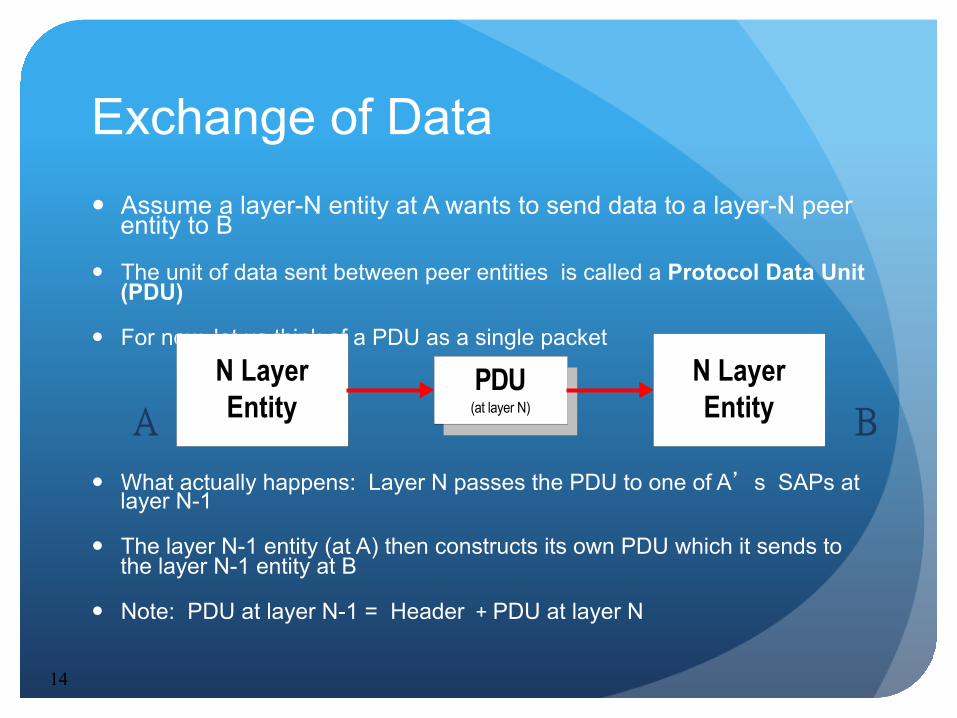
Exchange of Data Assume a layer-N entity at A wants to send data to a layer-N peer
entity to B
The unit of data sent between peer entities is called a Protocol Data Unit (PDU)
For now, let us think of a PDU as a single packet
What actually happens: Layer N passes the PDU to one of A’s SAPs at layer N-1
The layer N-1 entity (at A) then constructs its own PDU which it sends to the layer N-1 entity at B
Note: PDU at layer N-1 = Header + PDU at layer N
N LayerEntity
PDU(at layer N)
N LayerEntityA B
15
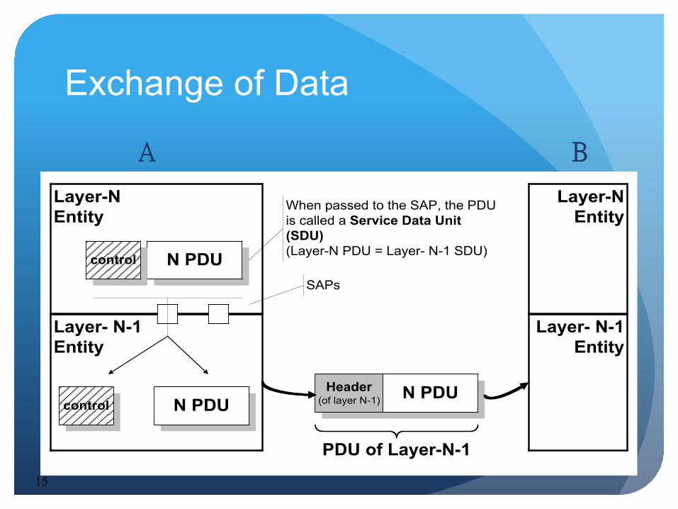
Exchange of Data
Layer-NEntity
N PDU
Layer- N-1Entity
When passed to the SAP, the PDUis called a Service Data Unit(SDU)(Layer-N PDU = Layer- N-1 SDU)
SAPs
control
N PDUcontrolHeader
(of layer N-1) N PDU
PDU of Layer-N-1
Layer-NEntity
Layer- N-1Entity
A B
16
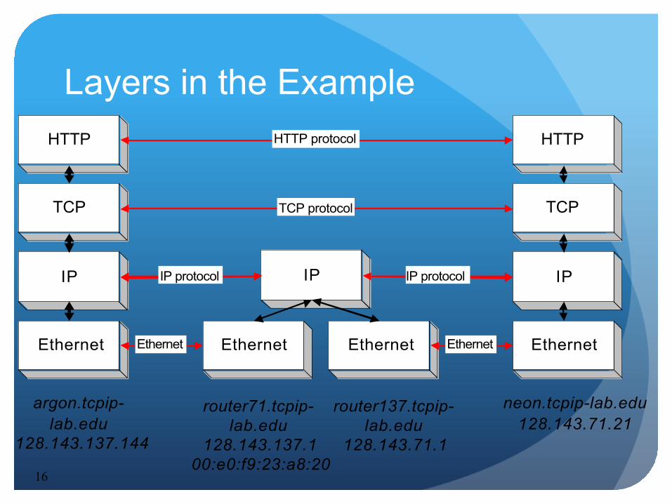
Layers in the Example HTTP
TCP
IP
argon.tcpip-lab.edu
128.143.137.144
Ethernet Ethernet Ethernet
IP
HTTP
TCP
IP
neon.tcpip-lab.edu128.143.71.21
Ethernet
router71.tcpip-lab.edu
128.143.137.100:e0:f9:23:a8:20
router137.tcpip-lab.edu
128.143.71.1
HTTP protocol
TCP protocol
IP protocol
Ethernet
IP protocol
Ethernet

17
Layers in the Example HTTP
TCP
IP
argon.tcpip-lab.edu
128.143.137.144
Ethernet Ethernet Ethernet
IP
HTTP
TCP
IP
neon.tcpip-lab.edu128.143.71.21
Ethernet
router71.tcpip-lab.edu
128.143.137.100:e0:f9:23:a8:20
router137.tcpip-lab.edu128.143.71.1
Send HTTP Request to neon
Establish a connection to 128.143.71.21 at port 80 Open TCP connection to
128.143.71.21 port 80
Send a datagram (which contains a connection request) to 128.143.71.21 Send IP datagram to
128.143.71.21
Send the datagram to 128.143.137.1
Send Ethernet frame to 00:e0:f9:23:a8:20
Send Ethernet frame to 00:20:af:03:98:28
Send IP data-gram to 128.143.71.21
Send the datagram to 128.143.7.21
Frame is an IP datagram
Frame is an IP datagram
IP datagram is a TCP segment for port 80
18
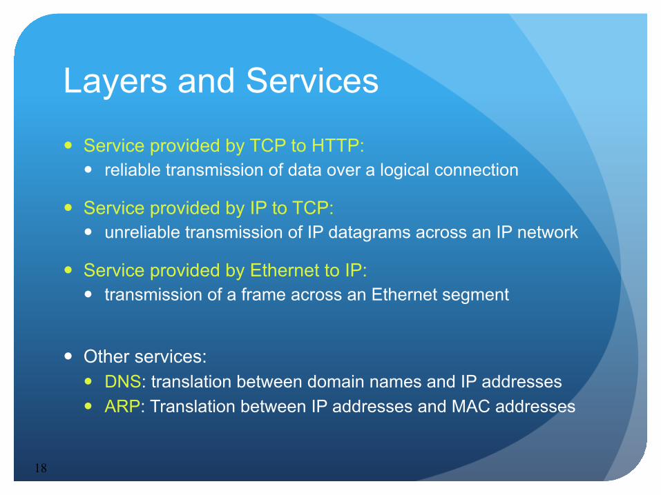
Layers and Services
Service provided by TCP to HTTP: reliable transmission of data over a logical connection
Service provided by IP to TCP: unreliable transmission of IP datagrams across an IP network
Service provided by Ethernet to IP: transmission of a frame across an Ethernet segment
Other services: DNS: translation between domain names and IP addresses ARP: Translation between IP addresses and MAC addresses
19
Encapsulation and Demultiplexing
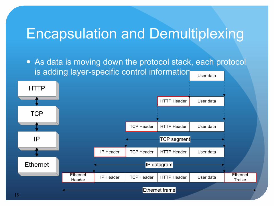
As data is moving down the protocol stack, each protocol is adding layer-specific control information
HTTP
TCP
IP
Ethernet
User data
User dataHTTP Header
TCP Header
TCP HeaderIP Header
TCP HeaderIP HeaderEthernetHeader
EthernetTrailer
IP datagram
TCP segment
Ethernet frame
User dataHTTP Header
User dataHTTP Header
User dataHTTP Header
20
Encapsulation and Demultiplexing in our Example
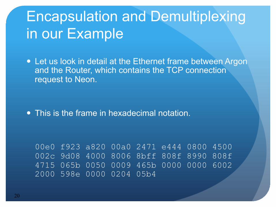
Let us look in detail at the Ethernet frame between Argon and the Router, which contains the TCP connection request to Neon.
This is the frame in hexadecimal notation.
00e0 f923 a820 00a0 2471 e444 0800 4500 002c 9d08 4000 8006 8bff 808f 8990 808f 4715 065b 0050 0009 465b 0000 0000 6002 2000 598e 0000 0204 05b4
21
Encapsulation and Demultiplexing
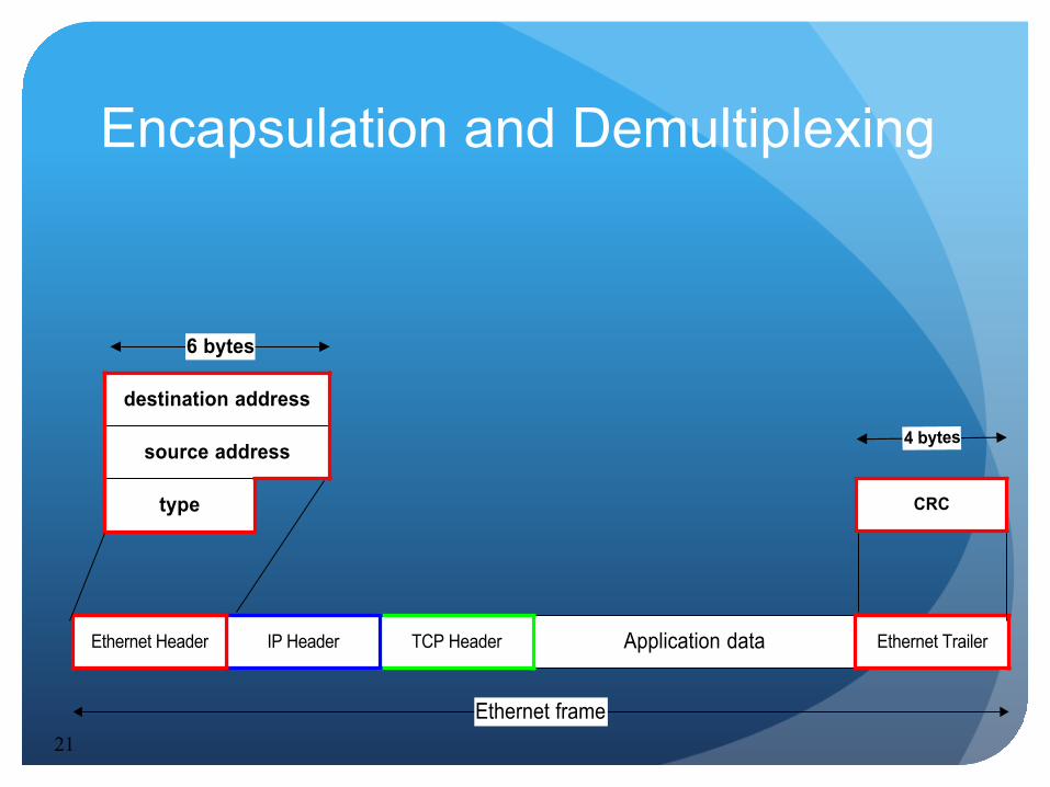
Application dataTCP HeaderIP HeaderEthernet Header Ethernet Trailer
Ethernet frame
destination address
source address
type
6 bytes
CRC
4 bytes

22
00:e0:f9:23:a8:20
0:a0:24:71:e4:44
0x0800
6 bytes
CRC
4 bytes
Encapsulation and Demultiplexing: Ethernet Header
Application dataTCP HeaderIP HeaderEthernet Header Ethernet Trailer
Ethernet frame

23
Encapsulation and Demultiplexing: IP Header
Application dataTCP HeaderEthernet Header Ethernet Trailer
Ethernet frame
IP Header
DS ECNversion(4 bits)
headerlength
Total Length (in bytes)(16 bits)
Identification (16 bits) flags(3 bits) Fragment Offset (13 bits)
Source IP address (32 bits)
Destination IP address (32 bits)
TTL Time-to-Live(8 bits)
Protocol(8 bits) Header Checksum (16 bits)
32 bits
24
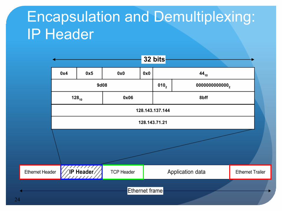
Encapsulation and Demultiplexing: IP Header
Application dataTCP HeaderEthernet Header Ethernet Trailer
Ethernet frame
IP Header
0x0 0x00x4 0x5 4410
9d08 0102 00000000000002
128.143.137.144
128.143.71.21
12810 0x06 8bff
32 bits
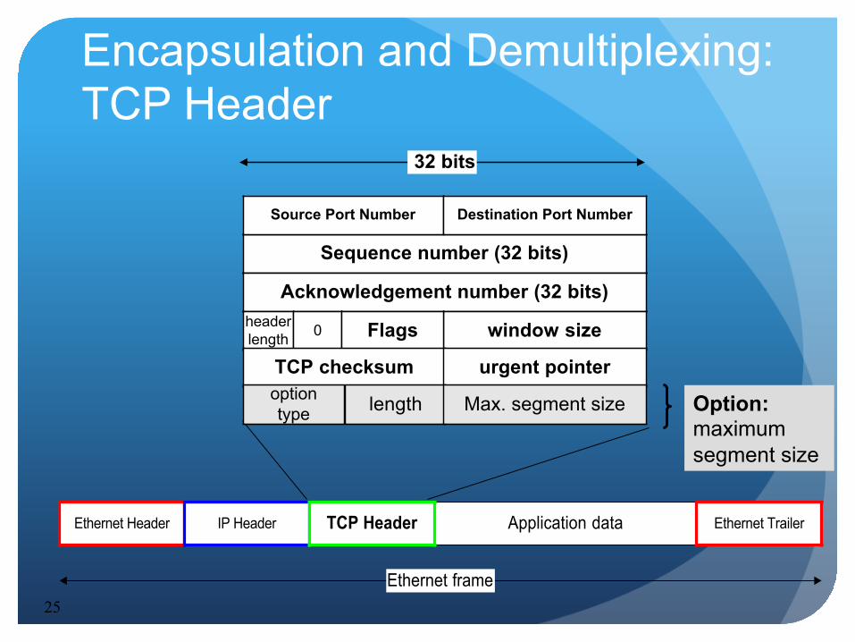
25
Encapsulation and Demultiplexing: TCP Header
Application dataEthernet Header Ethernet Trailer
Ethernet frame
IP Header TCP Header
Sequence number (32 bits)
Source Port Number Destination Port Number
Acknowledgement number (32 bits)
window sizeheaderlength 0 Flags
TCP checksum urgent pointer
32 bits
length Max. segment sizeoptiontype Option:
maximum segment size
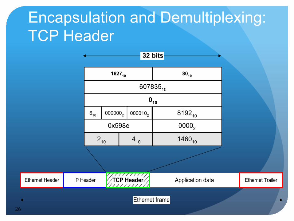
26
Encapsulation and Demultiplexing: TCP Header
Application dataEthernet Header Ethernet Trailer
Ethernet frame
IP Header TCP Header
60783510
162710 8010
010
819210610 0000002 0000102
0x598e 00002
32 bits
410 146010210
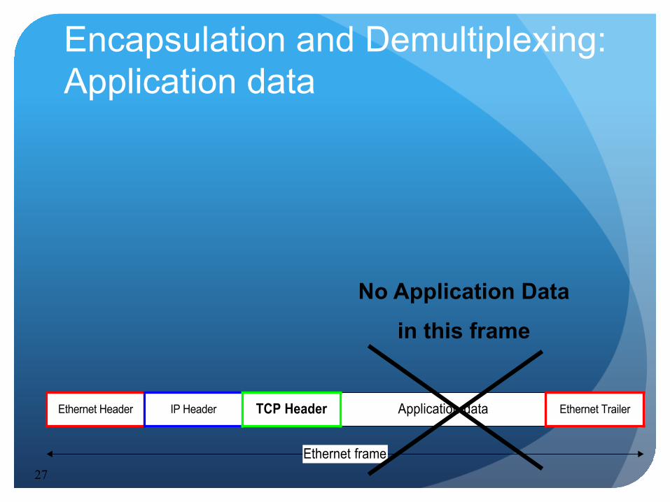
27
Encapsulation and Demultiplexing: Application data
Application dataEthernet Header Ethernet Trailer
Ethernet frame
IP Header TCP Header
No Application Data
in this frame
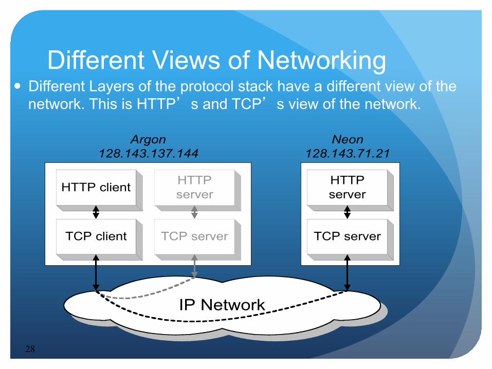
28
Different Views of Networking Different Layers of the protocol stack have a different view of the
network. This is HTTP’s and TCP’s view of the network.
HTTP client
TCP client
Argon128.143.137.144
HTTPserver
TCP server
Neon128.143.71.21
IP Network
HTTPserver
TCP server
29
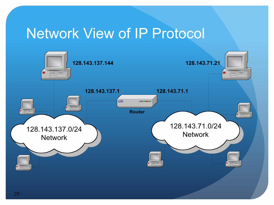
Network View of IP Protocol
128.143.71.21128.143.137.144
Router
128.143.137.0/24Network
128.143.137.1 128.143.71.1
128.143.71.0/24Network
30
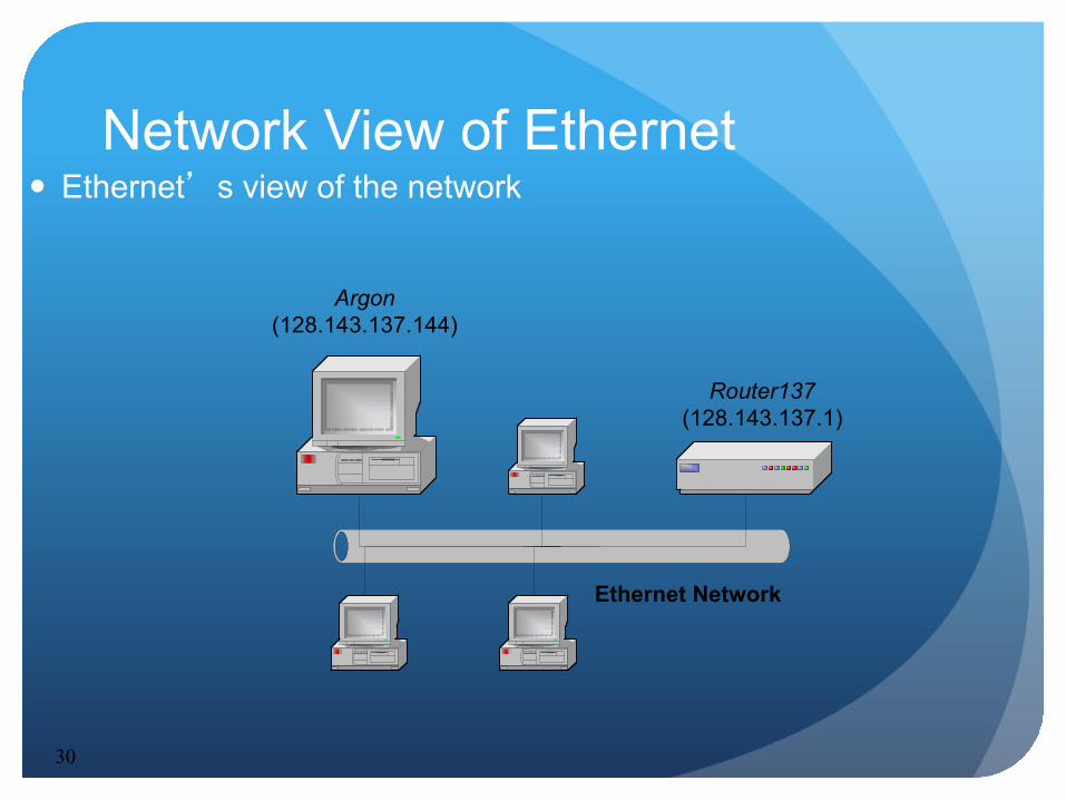
Network View of Ethernet Ethernet’s view of the network
Argon(128.143.137.144)
Router137(128.143.137.1)
Ethernet Network
IP Addresses
Structure of an IP address
Subnetting
CIDR
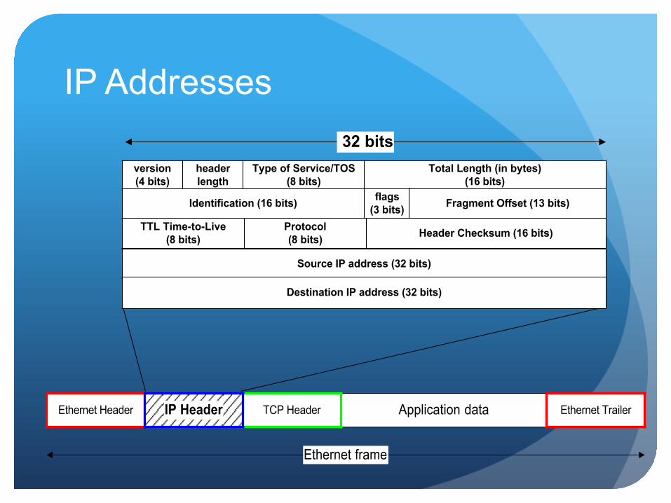
IP Addresses
Application dataTCP HeaderEthernet Header Ethernet Trailer
Ethernet frame
IP Header
version(4 bits)
headerlength
Type of Service/TOS(8 bits)
Total Length (in bytes)(16 bits)
Identification (16 bits) flags(3 bits) Fragment Offset (13 bits)
Source IP address (32 bits)
Destination IP address (32 bits)
TTL Time-to-Live(8 bits)
Protocol(8 bits) Header Checksum (16 bits)
32 bits

IP Addresses
Application dataTCP HeaderEthernet Header Ethernet Trailer
Ethernet frame
IP Header
0x4 0x5 0x00 4410
9d08 0102 00000000000002
128.143.137.144
128.143.71.21
12810 0x06 8bff
32 bits
What is an IP Address?
An IP address is a unique global address for a network interface
An IP address: is a 32 bit long identifier encodes a network number (network prefix) and a host
number
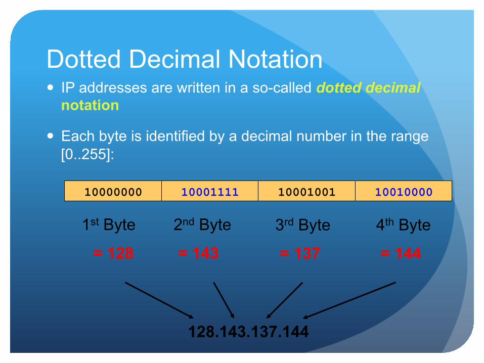
Dotted Decimal Notation IP addresses are written in a so-called dotted decimal
notation
Each byte is identified by a decimal number in the range [0..255]:
10001111 10000000 10001001 10010000
1st Byte
= 128
2nd Byte
= 143
3rd Byte
= 137
4th Byte
= 144
128.143.137.144
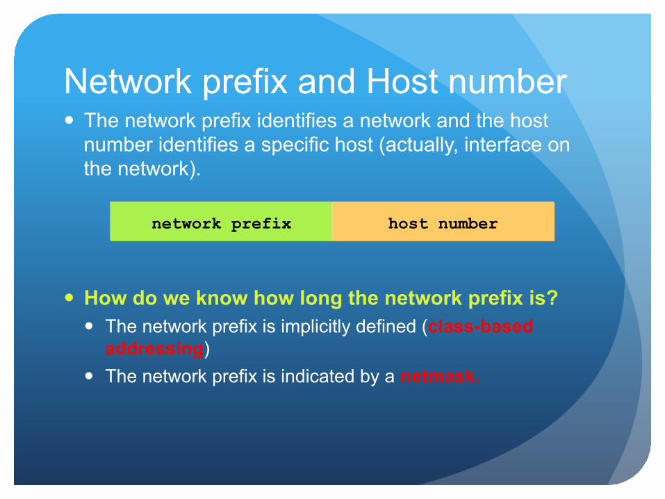
The network prefix identifies a network and the host number identifies a specific host (actually, interface on the network).
How do we know how long the network prefix is? The network prefix is implicitly defined (class-based
addressing) The network prefix is indicated by a netmask.
Network prefix and Host number
network prefix host number
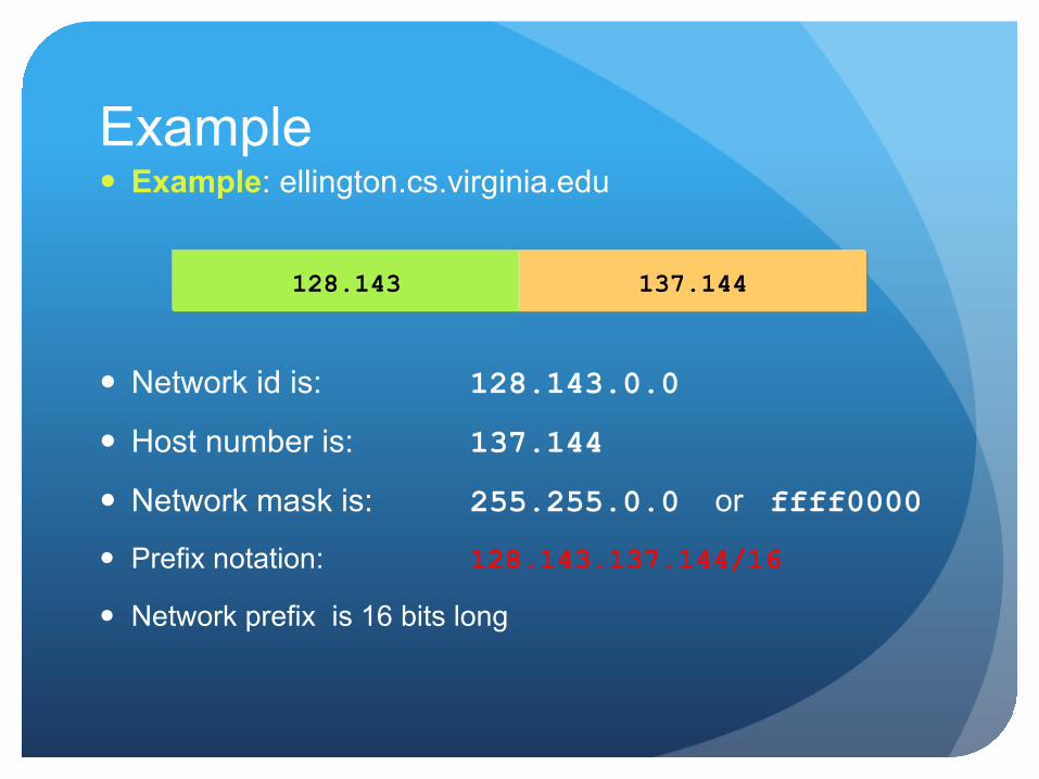
Example: ellington.cs.virginia.edu
Network id is: 128.143.0.0
Host number is: 137.144
Network mask is: 255.255.0.0 or ffff0000
Prefix notation: 128.143.137.144/16
Network prefix is 16 bits long
Example
128.143 137.144
The old way: Classful IP Adresses
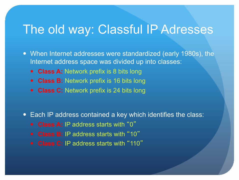
When Internet addresses were standardized (early 1980s), the Internet address space was divided up into classes: Class A: Network prefix is 8 bits long Class B: Network prefix is 16 bits long Class C: Network prefix is 24 bits long
Each IP address contained a key which identifies the class: Class A: IP address starts with “0” Class B: IP address starts with “10” Class C: IP address starts with “110”
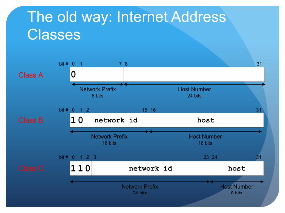
The old way: Internet Address Classes
Class C network id host11 0
Network Prefix24 bits
Host Number8 bits
bit # 0 1 23 242 313
Class B 1 network id hostbit # 0 1 15 162
Network Prefix16 bits
Host Number16 bits
031
Class A 0Network Prefix
8 bits
bit # 0 1 7 8
Host Number24 bits
31
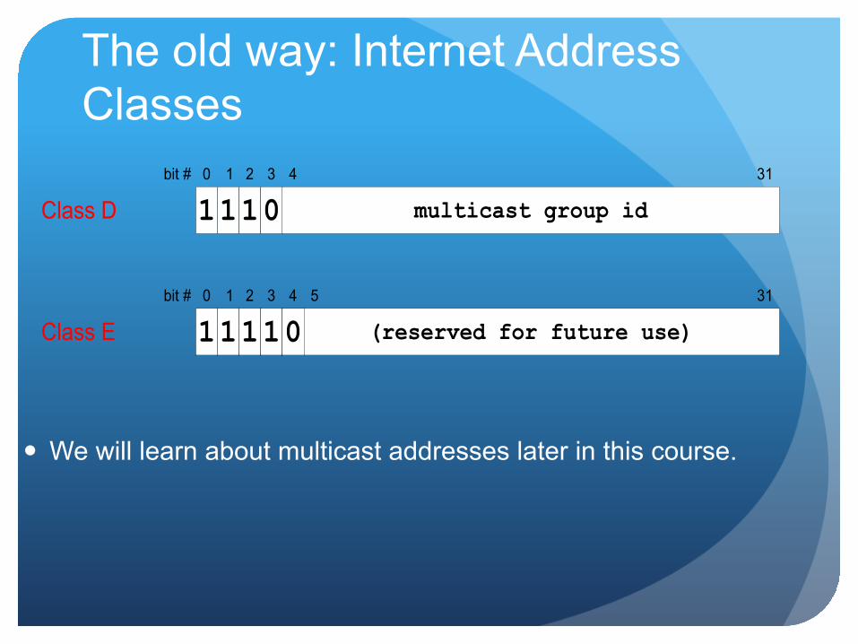
Class D multicast group id11 1bit # 0 1 2 313
04
Class E (reserved for future use)11 1bit # 0 1 2 313
14
05
The old way: Internet Address Classes
We will learn about multicast addresses later in this course.
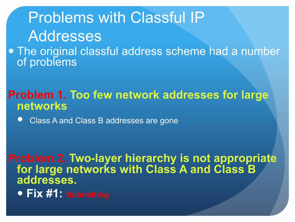
Problems with Classful IP Addresses
The original classful address scheme had a number of problems
Problem 1. Too few network addresses for large networks Class A and Class B addresses are gone
Problem 2. Two-layer hierarchy is not appropriate for large networks with Class A and Class B addresses. Fix #1: Subnetting

Problems with Classful IP Addresses
Problem 3. Inflexible. Assume a company requires 2,000 addresses Class A and B addresses are overkill Class C address is insufficient (requires 8 Class C addresses)
Fix #2: Classless Interdomain Routing (CIDR)
Problems with Classful IP Addresses
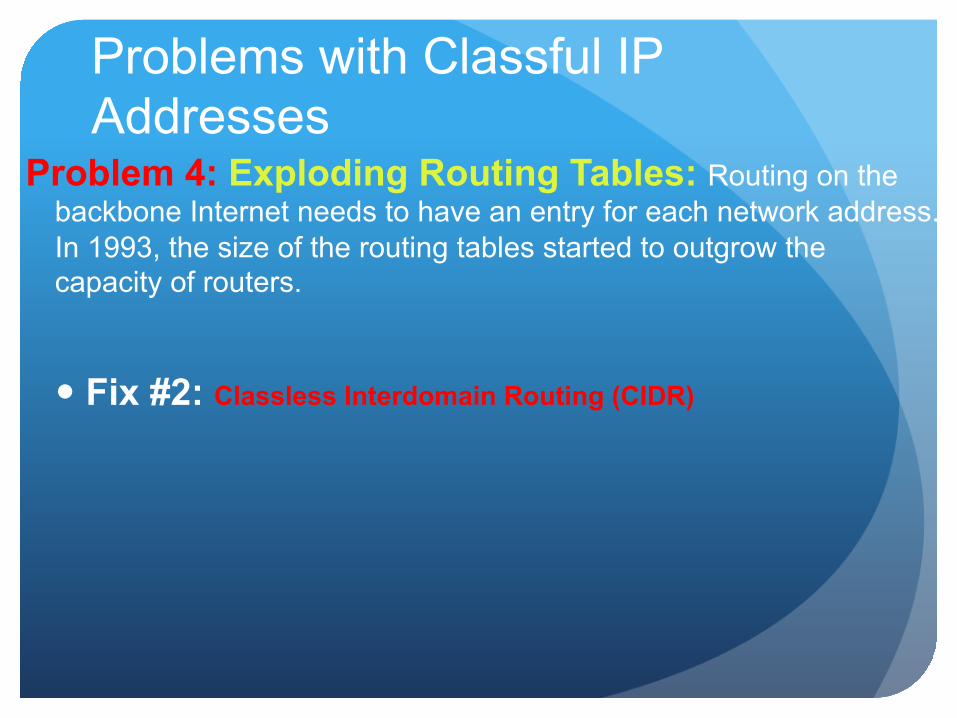
Problem 4: Exploding Routing Tables: Routing on the backbone Internet needs to have an entry for each network address. In 1993, the size of the routing tables started to outgrow the capacity of routers.
Fix #2: Classless Interdomain Routing (CIDR)

Problems with Classful IP Addresses
Problem 5. The Internet is going to outgrow the 32-bit addresses
Fix #3: IP Version 6
Subnetting
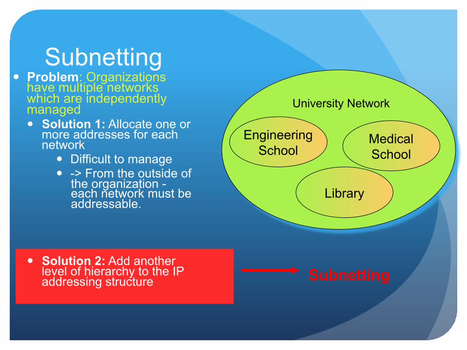
Subnetting Problem: Organizations
have multiple networks which are independently managed Solution 1: Allocate one or
more addresses for each network
Difficult to manage -> From the outside of
the organization - each network must be addressable.
Solution 2: Add another level of hierarchy to the IP addressing structure
University Network
Medical School
Library
Engineering School
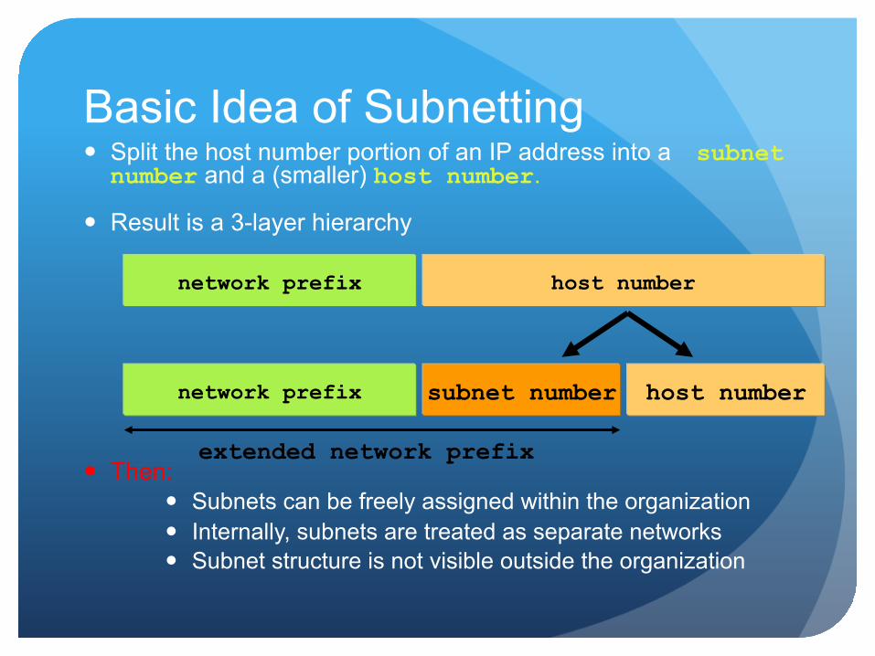
Basic Idea of Subnetting Split the host number portion of an IP address into a subnet number and a (smaller) host number.
Result is a 3-layer hierarchy
Then: Subnets can be freely assigned within the organization Internally, subnets are treated as separate networks Subnet structure is not visible outside the organization
network prefix host number
subnet number network prefix host number
extended network prefix
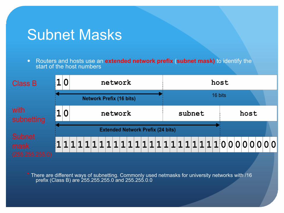
Routers and hosts use an extended network prefix (subnet mask) to identify the start of the host numbers
* There are different ways of subnetting. Commonly used netmasks for university networks with /16 prefix (Class B) are 255.255.255.0 and 255.255.0.0
Class B network host
16 bits
withsubnetting
host
Subnetmask(255.255.255.0)
network subnet
Network Prefix (16 bits)
1
1111111111111111111111100000000
0
10Extended Network Prefix (24 bits)
Subnet Masks
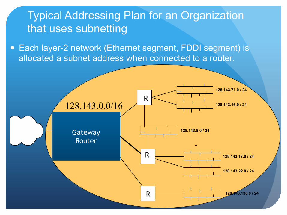
Each layer-2 network (Ethernet segment, FDDI segment) is allocated a subnet address when connected to a router.
128.143.17.0 / 24
128.143.71.0 / 24
128.143.7.0 / 24
128.143.16.0 / 24
128.143.8.0 / 24
128.143.22.0 / 24
128.143.136.0 / 24
Typical Addressing Plan for an Organization that uses subnetting
128.143.0.0/16
Gateway Router
R
R
R
Advantages of Subnetting With subnetting, IP addresses use a 3-layer hierarchy:
Network Subnet Host
Improves efficiency of IP addresses by not consuming an entire address space for each physical network.
Reduces router complexity. Since external routers do not know about subnetting, the complexity of routing tables at external routers is reduced.
Note: Length of the subnet mask need not be identical at all subnetworks.
CIDR - Classless Interdomain Routing IP backbone routers have one routing table entry for each
network address: With subnetting, a backbone router only needs to know one
entry for each network This is acceptable for Class A and Class B networks
27 = 128 Class A networks 214 = 16,384 Class B networks
But this is not acceptable for Class C networks 221 = 2,097,152 Class C networks
In 1993, the size of the routing tables started to outgrow the capacity of routers
Consequence: The Class-based assignment of IP addresses had to be abandoned
CIDR - Classless Interdomain Routing
Goals: Restructure IP address assignments to increase efficiency Hierarchical routing aggregation to minimize route table
entries
Key Concept: The length of the network id (prefix) in the IP addresses is kept arbitrary
Consequence: Routers advertise the IP address and the length of the prefix
CIDR Example
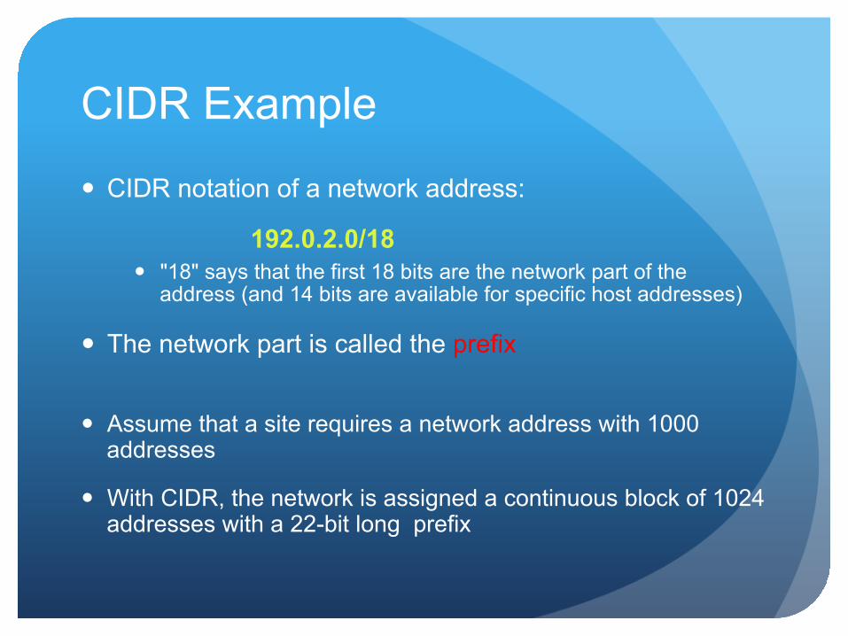
CIDR notation of a network address:
192.0.2.0/18 "18" says that the first 18 bits are the network part of the
address (and 14 bits are available for specific host addresses)
The network part is called the prefix
Assume that a site requires a network address with 1000 addresses
With CIDR, the network is assigned a continuous block of 1024 addresses with a 22-bit long prefix
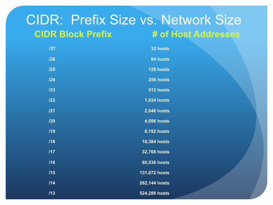
CIDR: Prefix Size vs. Network Size CIDR Block Prefix # of Host Addresses /27 32 hosts
/26 64 hosts
/25 128 hosts
/24 256 hosts
/23 512 hosts
/22 1,024 hosts
/21 2,048 hosts
/20 4,096 hosts
/19 8,192 hosts
/18 16,384 hosts
/17 32,768 hosts
/16 65,536 hosts
/15 131,072 hosts
/14 262,144 hosts
/13 524,288 hosts
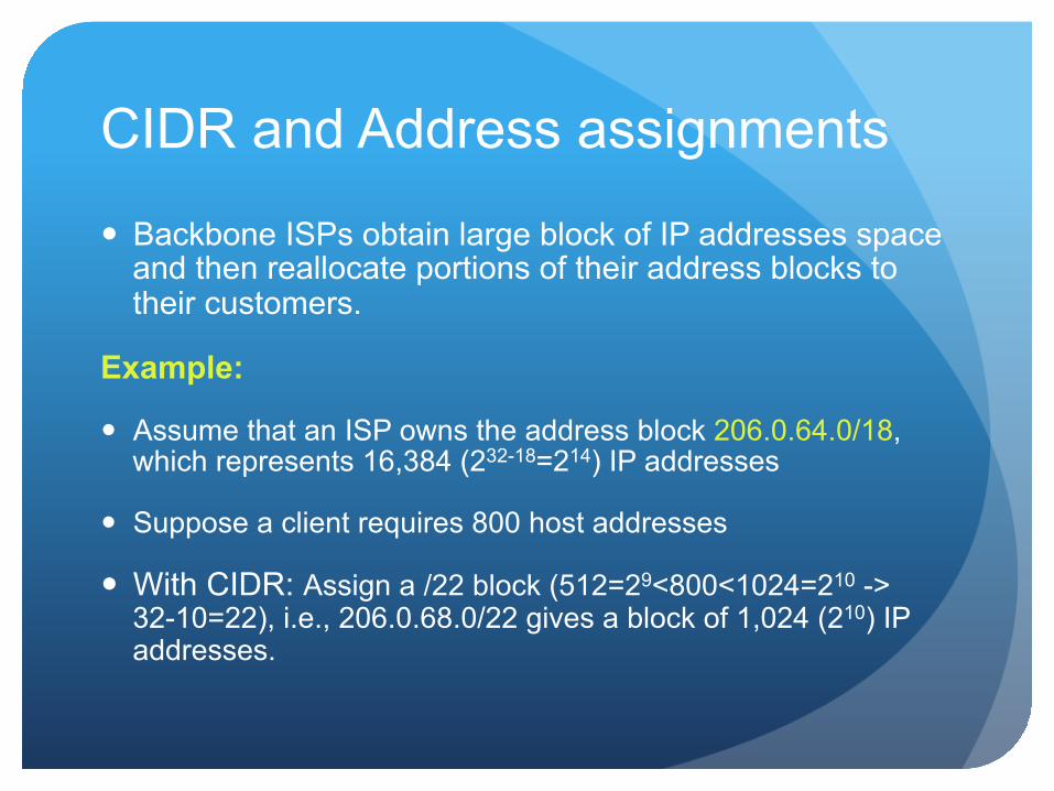
CIDR and Address assignments
Backbone ISPs obtain large block of IP addresses space and then reallocate portions of their address blocks to their customers.
Example:
Assume that an ISP owns the address block 206.0.64.0/18, which represents 16,384 (232-18=214) IP addresses
Suppose a client requires 800 host addresses
With CIDR: Assign a /22 block (512=29<800<1024=210 -> 32-10=22), i.e., 206.0.68.0/22 gives a block of 1,024 (210) IP addresses.
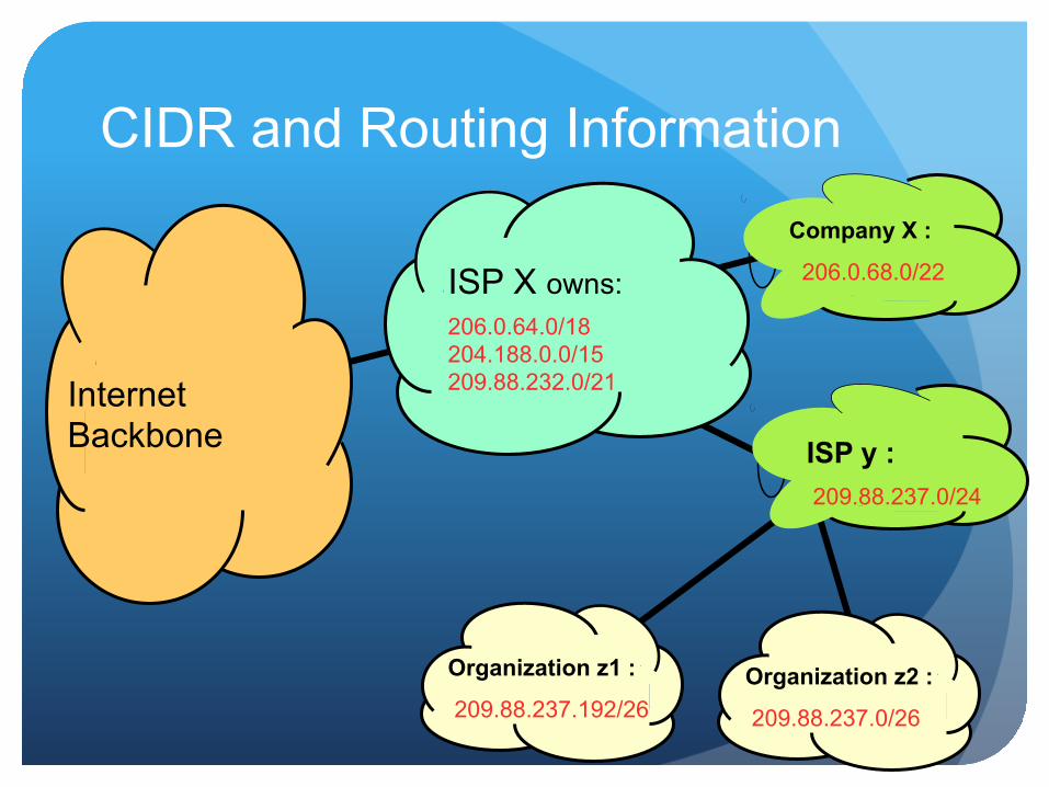
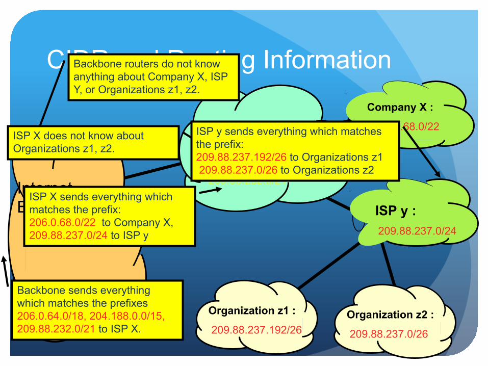
CIDR and Routing Information
206.0.64.0/18 204.188.0.0/15 209.88.232.0/21 Internet
Backbone
ISP X owns: Company X : 206.0.68.0/22
ISP y : 209.88.237.0/24
Organization z1 : 209.88.237.192/26
Organization z2 : 209.88.237.0/26
CIDR and Routing Information
206.0.64.0/18 204.188.0.0/15 209.88.232.0/21 Internet
Backbone
ISP X owns: Company X : 206.0.68.0/22
ISP y : 209.88.237.0/24
Organization z1 : 209.88.237.192/26
Organization z2 : 209.88.237.0/26
Backbone sends everything which matches the prefixes 206.0.64.0/18, 204.188.0.0/15, 209.88.232.0/21 to ISP X.
ISP X sends everything which matches the prefix: 206.0.68.0/22 to Company X, 209.88.237.0/24 to ISP y
Backbone routers do not know anything about Company X, ISP Y, or Organizations z1, z2.
ISP X does not know about Organizations z1, z2.
ISP y sends everything which matches the prefix: 209.88.237.192/26 to Organizations z1 209.88.237.0/26 to Organizations z2
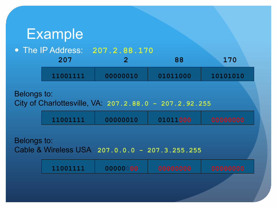
Example
Belongs to: Cable & Wireless USA 207.0.0.0 - 207.3.255.255
11001111 00000010
207 2
01011000
88
10101010
170
11001111 00000010 01011000 00000000
Belongs to: City of Charlottesville, VA: 207.2.88.0 - 207.2.92.255
11001111 00000000 00000000 00000000
The IP Address: 207.2.88.170
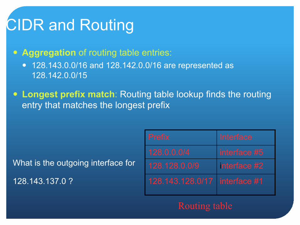
CIDR and Routing Aggregation of routing table entries:
128.143.0.0/16 and 128.142.0.0/16 are represented as 128.142.0.0/15
Longest prefix match: Routing table lookup finds the routing entry that matches the longest prefix
What is the outgoing interface for
128.143.137.0 ?
Prefix Interface
128.0.0.0/4 interface #5 128.128.0.0/9 interface #2
128.143.128.0/17 interface #1
Routing table