Chapter 3 Project Description 3.1 Introduction
58
Draft EIR September 2007 PdV Wind Energy Project 3-1 002147.EX09.01 Chapter 3 Project Description 3.1 Introduction This EIR has been prepared to identify and evaluate potential environmental impacts associated with implementation of Power Partners Southwest, LLC’s (the applicant's), proposed PdV Wind Energy project (the project). This project is also called the Manzana Wind. The proposed project requires approval of a zone change and a conditional use permit and if approved would allow for the commercial production of up to 300 megawatts (MW) of electricity from wind turbines. The project is located west of the Willow Springs area, north of Rosamond Boulevard and 170 th Street West in eastern Kern County (the County), as shown in Figure 1-1. The project is entirely on privately owned land under long-term leases with the landowners and would be privately owned by PPM Manzana LLC and commercially financed. Power generated at the project would be transferred to SCE’s 220 kilovolt (kV) and/or 500 kV transmission system as described in the SCE Tehachapi Renewable Transmission Project System upgrades and the CAISO Regional Transmission Plan. The power would then be sold to a power purchaser (via a power purchase agreement), who in turn would sell energy output to California investor-owned utilities, municipalities, or other purchasers, in furtherance of the goals of the California Renewable Energy Portfolio Standards and other similar renewable programs in the State. 3.2 Proposed Project The proposed project is located on a 5,820-acre project site, defined as the area within the project boundary, as shown in Figure 1-2. The applicant is requesting a change in zone classification to incorporate the Wind Energy (WE) Combining District on approximately 3,372 acres of the 5,820-acre project site in the Willow Springs area of eastern Kern County. Those portions of the project site subject to the zone change proposal are designated on the Kern County General Plan as follows:
Transcript of Chapter 3 Project Description 3.1 Introduction

Draft EIR September 2007 PdV Wind Energy Project 3-1 002147.EX09.01
Chapter 3 Project Description
3.1 Introduction This EIR has been prepared to identify and evaluate potential environmental impacts associated with implementation of Power Partners Southwest, LLC’s (the applicant's), proposed PdV Wind Energy project (the project). This project is also called the Manzana Wind. The proposed project requires approval of a zone change and a conditional use permit and if approved would allow for the commercial production of up to 300 megawatts (MW) of electricity from wind turbines. The project is located west of the Willow Springs area, north of Rosamond Boulevard and 170th Street West in eastern Kern County (the County), as shown in Figure 1-1. The project is entirely on privately owned land under long-term leases with the landowners and would be privately owned by PPM Manzana LLC and commercially financed. Power generated at the project would be transferred to SCE’s 220 kilovolt (kV) and/or 500 kV transmission system as described in the SCE Tehachapi Renewable Transmission Project System upgrades and the CAISO Regional Transmission Plan. The power would then be sold to a power purchaser (via a power purchase agreement), who in turn would sell energy output to California investor-owned utilities, municipalities, or other purchasers, in furtherance of the goals of the California Renewable Energy Portfolio Standards and other similar renewable programs in the State.
3.2 Proposed Project The proposed project is located on a 5,820-acre project site, defined as the area within the project boundary, as shown in Figure 1-2. The applicant is requesting a change in zone classification to incorporate the Wind Energy (WE) Combining District on approximately 3,372 acres of the 5,820-acre project site in the Willow Springs area of eastern Kern County. Those portions of the project site subject to the zone change proposal are designated on the Kern County General Plan as follows:
County of Kern Chapter 3. Project Description
Draft EIR September 2007 PdV Wind Energy Project 3-2 002147.EX09.01
8.3 (Extensive Agriculture);
8.2/ 2.1 (Extensive Agriculture – Seismic Hazard);
8.3/2.4 (Extensive Agriculture – Steep Slope);
8.3/2.5 (Extensive Agriculture – Flood Hazard); and
8.4 (Mineral and Petroleum).
The site zoning is currently a combination of:
A (Exclusive Agriculture);
A-GH (Exclusive Agriculture – Geologic Hazard Combining District); and
A-FP (Exclusive Agriculture – Floodplain Combining District).
Implementation of the project would require:
Amendment of Zone Map 216 (Zone Change Case No. 3, Map 216);
A change in zone classification from A (Exclusive Agriculture) to A-WE (Exclusive Agriculture – Wind Energy Combining District) on 2,752 acres;
A change in zone classification from A-GH (Exclusive Agriculture – Geologic Hazard Combining District) to A-WE GH (Exclusive Agriculture – Wind Energy Combining – Geologic Hazard Combining District) on 249 acres;
A change in zone classification from A-FP (Exclusive Agriculture – Floodplain Combining District) to A WE FP (Exclusive Agriculture – Wind Energy Combining- Wind Energy Combining District) on 54 acres;
Amendment of Zone Map 233 (Zone Change Case No. 10, Map 233);
A change in zone classification from A (Exclusive Agriculture) to A-WE (Exclusive Agriculture – Wind Energy Combining District on 97 acres;
A change in zone classification from A-FP (Exclusive Agriculture– Floodplain Combining District) to A-WE FP (Exclusive Agriculture – Wind Energy Combining – Floodplain Combining District) on 220 acres; and
A total requested acreage zone classification to WE of 3372.

County of Kern Chapter 3. Project Description
Draft EIR September 2007 PdV Wind Energy Project 3-3 002147.EX09.01
The purpose of the WE Combining District is to promote the use of an alternative to fossil fuel-generated electrical power in areas of the County that are identified as having wind resources suitable for producing commercial quantities of wind-generated electrical power. Figure 1-3 illustrates the locations where the existing base zone district would have the WE Combining District added. Within the areas that would have the WE Combining District added to their base zone district, the applicant proposes to install between 100 and 300 wind turbines (depending on the turbine model used) and associated facilities, such as roads, an operations and maintenance (O&M) building, a new PdV substation, and power lines. The applicant is also requesting approval of a conditional use permit (CUP 2, Map No. 216) to allow the temporary use of concrete batch plants to provide concrete and materials for turbine, PdV substation, and operation and maintenance building foundations. The batch plants would be on site during construction only.
3.3 Project Objectives The applicant’s objectives for the project are to:
Provide up to 300 MW of installed electrical capacity;
Be a major supplier of clean renewable energy, meeting the growing demands of California consumers;
Realize the full potential of the wind resource on the lands under lease;
Promote the long-term viability of agricultural uses in the project area;
Assist California in meeting its legislated Renewable Energy Portfolio Standards for the generation of renewable energy in the state, which require investor-owned utilities to purchase 20% of their power from renewable sources by the year 2017;
Offset the need for additional electricity generated from fossil fuels and assist the State in meeting its air quality and greenhouse gas reduction goals;
Result in an economically feasible wind energy project that would be developed through commercially available financing;
Assist Kern County in promoting its role as the State’s leading renewable energy county;

County of Kern Chapter 3. Project Description
Draft EIR September 2007 PdV Wind Energy Project 3-4 002147.EX09.01
Provide temporary local employment opportunity for the greater area during the construction phase;
Provide long-term local employment opportunity in the O&M facility;
Displace the 540,000 tons of carbon dioxide (a greenhouse gas) emissions per year to generate the same amount of electricity as this 300 MW wind project;
Displace 2,700 tons of sulfur dioxide emissions per year;
Displace 1,200 tons of nitrogen oxide emissions per year;
Displace the fossil fuel consumption equivalent of burning 8,700,000 tons of coal (a line of 10-ton trucks 3,300 miles long) or 27,600,000 barrels of oil over a 20-year period;
Supply clean, safe, renewable energy for approximately 90,000 homes;
Play a role in helping California meet its Climate Action Initiative goal of reducing greenhouse gases to 1990 emission levels by 2020, as required by recently passed bipartisan legislation (Assembly Bill 32); and
Support California's aggressive goal of 33% renewable energy generation by 2020.
3.4 Environmental Setting Regional Location
The project would be located along the southeastern foothills of the Tehachapi Mountains in the Willow Springs area of eastern Kern County. The Energy Element of the Kern County General Plan describes the Tehachapi Mountains as one of California’s largest areas for wind energy development, responsible for about 40% of the state’s total wind-generated power. The project is located about 15 miles west of State Highway 14 (Antelope Valley Freeway) and 12.5 miles south of Highway 58 (see Figure 1-1). The project site is generally bounded to the north and west by the Tehachapi Mountains; to the south by the Los Angeles Aqueduct and beyond that, Rosamond Boulevard; and to the east by Tehachapi Willow Springs Road. The Pacific Crest Trail temporary alignment bisects the project site. Tejon Ranch is situated directly west of the project site, while Willow Springs International Motorsports Park, a recreational racetrack, is located approximately 10 miles to the east. Northrop Grumman Corporation maintains its Tejon Test Site approximately 3 miles to the west. The unincorporated

County of Kern Chapter 3. Project Description
Draft EIR September 2007 PdV Wind Energy Project 3-5 002147.EX09.01
community of Rosamond and Edwards Air Force Base are located about 15 miles to the southeast. The project site is located on the U.S. Geological Survey 7.5-minute Tylerhorse Canyon topographic quadrangle, in two townships. In Township 9 North, Range 15 West, S.B.B&M, the project spans a portion of Sections 2 and 4; in Township 10 North, Range 15 West, S.B.B&M, the project spans all or a portion of the following Sections: 4, 9, 15, 16, 22, 23, 26, 27, 28, 32, 33, 34, and 35 (see Figure 1-2).
Project Site Existing Conditions The project would be placed entirely on private land owned by over 45 private landowners in a remote, sparsely populated, rural area of Kern County. To characterize existing conditions at the project site, in-depth environmental studies of the proposed site were conducted. These studies included surveys for biological, cultural, and hydrologic resources; an assessment of existing hazards associated with hazardous waste and geologic conditions; and an evaluation of air quality and noise conditions. The surveys were designed to characterize the areas most likely to be affected by temporary and permanent impacts within the area proposed for a zone change and the conditional use permit. The methodologies for the various surveys conducted are discussed in each resource section of Chapter 4 as applicable. Based on these studies, a constraints map identifying the location of sensitive resources and hazards was developed (see Figure 3-1). The constraints map is further described in Section 3.5.1 under “Infrastructure Siting Setbacks and Constraints.”
Land Use The project site is largely undeveloped. The exceptions are existing dirt roads that crisscross the project site. SCE’s existing power lines run diagonally near the southwestern corner of the project site. Of the land within the project site, 2,367 acres are subject to Williamson Act Land Use contracts. The primary purpose of the Williamson Act is to preserve agricultural lands from conversion to residential, industrial, or other non-agricultural or non-compatible uses during the term of a contract. Williamson Act contracts cover lands within the project area identified by the following Assessor Parcel Numbers: 476-010-14; 476-020-13; 476-020-11; 476-030-13; 476-020-14; 476-052-18; 476-110-01; 476-110-05; and 476-110-11. These lands have been used historically for livestock grazing.
County of Kern Chapter 3. Project Description
Draft EIR September 2007 PdV Wind Energy Project 3-6 002147.EX09.01
Development of wind turbines on these Williamson Act Contract properties is anticipated to remove 6% or less of the contracted lands within these properties from agricultural uses. The portion of the lands not used for turbines on the properties (94%) would remain available for livestock grazing. Additional detail on land use and zoning is provided below in Section 3.4.5, “Zoning and General Plan Land Use Designations,” and in Section 4.9, “Land Use and Planning.”
Geography The project is located along the southeastern edge of the Tehachapi Mountains. Topography of the project site ranges in elevation from a high point of about 5,613 feet above mean sea level in the northwest to about 2,975 feet above mean sea level in the southeast toward the Antelope Valley area. There are several small desert washes that traverse the area.
Vegetation The project site comprises native and non-native species typical of the upper Mojave Desert and lower reaches of the Tehachapi Mountains. Vegetation in lower elevations of the project site is typical of upper Mojave vegetation such as juniper woodland and Mojave Desert scrub, with extensive cover of introduced annual grasses. The western portion of middle elevations contains areas of native needle grass grassland. The eastern portion of the middle elevations is dominated by introduced annual grasses and Mojave Desert scrub vegetation. The upper elevations are pine oak woodlands typical of the middle elevations of the Tehachapi Mountains. Habitat in the project site is of average quality. The project site is incised by numerous desert washes. The only named surface water is Cottonwood Creek. Additional detail on vegetation, biological resources, and water resources in the project site is provided in Section 4.4, “Biological Resources,” and Section 4.8, “Hydrology and Water Quality.”
Surrounding Land Uses The land surrounding the project site is undeveloped desert scrub, rural residences, a calcite mining operation, and Northrop Grumman Corporation’s Tejon Test Site. The nearest developments are the Tejon Test Site, the calcite mine adjacent and northeast of the project site, and scattered rural residences situated around the project boundary. The

""
""
""
"" ""
""
""
""
""
""
10N15W
9N 15W 9N 15W10N 15W
5 2
9
4 3
24 31
29 28
1
34
27 26
3533
11
32
2322
14
21
10
16 15
24
5
25
13
12
36
8 9
8
1110
17
12
6
20
31
7
30
36353432 33631
© Ecology & Environment, Inc. GIS Department Project #002147.ex09.01\\BUFSDL4\GIS\SanFrancisco\PdV_Windfarm_II\Maps\MXDs\Updates\ProjectArea_constraints040607.mxd 4/6/2007
"" Residence
Project Area Boundary (4-7-06)
Section Boundary
Township Boundary
Drainage
LAAqueduct
Existing Roads
Pacific Crest Trail
San JoaquinPocket Mouse Habitat
USFWS NWI Wetland
Geologic Hazard Zone
Steep Slope
Flood Hazard Zone
Wind Energy Zone
Desert Native Grassland
{ { {
{ { {
Joshua Tree Woodland
Southern Willow Scrub
Oak Tree Area
Williamson Act Contract
Figure 3-1Environmental Constraints Map
PdV Wind Energy ProjectKern County, California
Project AreaBoundary
PaleontologicalSensitivity
L = Low Sensitivity
H = High Sensitivity
4
10N
d0 0.5 1 Miles
0 0.5 1 Kilometers

County of Kern Chapter 3. Project Description
Draft EIR September 2007 PdV Wind Energy Project 3-9 002147.EX09.01
locations of the residences relative to the project site are discussed in more depth in Section 4.11, “Noise.” The calcite mine, owned by California Portland Cement Company, is located adjacent to the project to the northeast in Sections 10, 15, and 14 of Township 10 North and Range 15.
Site Access Access to the project site would be from the corner of Rosamond Boulevard and north along 170th Street West to its terminus. From the terminus of 170th Street West, the applicant proposes to construct a new access road that would extend approximately 3.3 miles north into the southern boundary of the project site (see Section 3.5.1 under “Access Roads” for additional discussion). Within the project site is an existing network of private dirt roads that would be used to the greatest extent possible, as agreed to in the lease agreements with the landowner whose property the roads cross. It is anticipated that existing roads would require improvements to allow their use during construction. Improvements might include widening roads or replacing existing culverts or dry wash crossings across drainages with larger culverts to allow for safe use by construction equipment. The applicant would be required to consult with the County prior to improving roads. Additional discussion of access is provided below in Section 4.15, “Transportation and Traffic.”
Zoning and General Plan Land Use Designations The project requires a zone change, which will be reviewed for compatibility with land designation and zoning prescribed in the Kern County General Plan and Zoning Ordinance.
Kern County General Plan The General Plan identifies three land use designations within the project site. The project site is not located in an area covered by a specific plan. Section 4.9, “Land Use and Planning,” discusses existing land use designations at the project site area. Table 3-1 lists the land use designation of the acreage to be zone changed and the percentage of total zone change.
County of Kern Chapter 3. Project Description
Draft EIR September 2007 PdV Wind Energy Project 3-10 002147.EX09.01
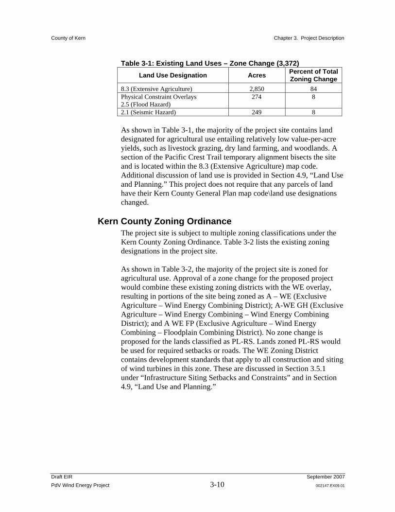
Table 3-1: Existing Land Uses – Zone Change (3,372) Land Use Designation Acres Percent of Total
Zoning Change 8.3 (Extensive Agriculture) 2,850 84 Physical Constraint Overlays 2.5 (Flood Hazard)
274 8
2.1 (Seismic Hazard) 249 8 As shown in Table 3-1, the majority of the project site contains land designated for agricultural use entailing relatively low value-per-acre yields, such as livestock grazing, dry land farming, and woodlands. A section of the Pacific Crest Trail temporary alignment bisects the site and is located within the 8.3 (Extensive Agriculture) map code. Additional discussion of land use is provided in Section 4.9, “Land Use and Planning.” This project does not require that any parcels of land have their Kern County General Plan map code\land use designations changed.
Kern County Zoning Ordinance The project site is subject to multiple zoning classifications under the Kern County Zoning Ordinance. Table 3-2 lists the existing zoning designations in the project site. As shown in Table 3-2, the majority of the project site is zoned for agricultural use. Approval of a zone change for the proposed project would combine these existing zoning districts with the WE overlay, resulting in portions of the site being zoned as A – WE (Exclusive Agriculture – Wind Energy Combining District); A-WE GH (Exclusive Agriculture – Wind Energy Combining – Wind Energy Combining District); and A WE FP (Exclusive Agriculture – Wind Energy Combining – Floodplain Combining District). No zone change is proposed for the lands classified as PL-RS. Lands zoned PL-RS would be used for required setbacks or roads. The WE Zoning District contains development standards that apply to all construction and siting of wind turbines in this zone. These are discussed in Section 3.5.1 under “Infrastructure Siting Setbacks and Constraints” and in Section 4.9, “Land Use and Planning.”

County of Kern Chapter 3. Project Description
Draft EIR September 2007 PdV Wind Energy Project 3-11 002147.EX09.01
Table 3-2: Existing Zoning Districts – Total Site (5,820 acres)
Zoning Designation Acres Percent of Total project Site
Exclusive Agriculture (A) 5,242 99 Exclusive Agriculture and Geologic Hazard (A-GH)
766 13 (overlay)
Exclusive Agriculture and Flood Plain Hazard (A-FP)
417 7 (overlay)
Military Review Requirements (Figure 19.08.160)
5,820 100
Wind Energy Combining District Zoning Ordinance In 1986, the Wind Energy (WE) Combining District was adopted as Chapter 19.46 of the Kern County Zoning Ordinance. The WE Combining District promotes the development of wind energy in Kern County and may be combined with any of the following zoning districts:
Exclusive Agriculture (A),
Industrial (M-1, M-2 and M-3), and
Natural Resource (NR) (with a minimum lot size of twenty acres), Recreation-Forestry (RF) (with a minimum lot size of 20 acres), Limited Agriculture (A-1) (with a minimum lot size of 20 acres), or Estate (E) (with a minimum lot size of 20 acres).
The WE Combining District allows for a variety of wind-energy related uses, including wind-driven electrical generators, accessory administrative and maintenance structures and facilities, electrical substations, transmission lines, and other such facilities and electrical structures related to the main use (Kern County Ordinance 19.64.020). The WE Combining District also allows other uses subject to a conditional use permit, including experimental wind-driven electrical generators and the manufacture and assembly of wind-driven electrical generators (Kern County Ordinance 19.64.030). Development within a WE zone requires approval of a detailed plot plan demonstrating compliance with any mitigation measures incorporated into any environmental documents adopted for the implementation of a WE district for specific parcels (Kern County Ordinance 19.64.130). The WE Combining District also regulates the development of wind energy projects in the district. For example, the WE Combining District regulates lot sizes, setbacks, and landscaping (Kern County Ordinance 19.64.050, 19.64.070, 19.64.080, 19.64.120). In particular, the WE
County of Kern Chapter 3. Project Description
Draft EIR September 2007 PdV Wind Energy Project 3-12 002147.EX09.01
Combining District establishes 600 feet as the maximum height for wind turbines, and specifies that the color of turbine blades and towers must be nonreflective and unobtrusive and that each turbine or the total project perimeter must be fenced (Kern County Ordinance 19.64.080, 19.64.140 (B) and (C)). The WE Combining District also requires that noise levels associated with turbine operations may not exceed 45 dBA for more than five minutes out of any one hour if the turbine is within 50 feet of any existing residence (Kern County Ordinance 19.64.140). However, a waiver may be obtained by the affected property owners acknowledging that they are aware of the noise, but consent to the noise limit in excess of those permitted in the ordinance (Kern County Ordinance 19.64.140 (J)(8)).
3.5 Proposed Project Characteristics Infrastructure
The applicant proposes to construct and operate the following infrastructure:
Up to 300 wind turbines, not to exceed 400 feet in height from ground elevation, with associated generators, towers, foundations, and pad-mounted transformers. Each turbine could range from 1 to 3 MW;
On-site roads and off-site project access roads, control cables, subsurface electrical feederline corridors, and power collection cables (transmission lines) necessary to serve the project;
A new PdV substation to step up the voltage generated by the turbines to meet the electrical transmission system’s 220 kV or 500 kV voltage (both 220 kV and 500 kV lines cross the site);
A 20-acre interconnection yard/switching station near the existing SCE 220 kV Antelope-Magunden power line to interconnect the facility with that line or the adjacent 500 kV transmission line;
An O&M building of about 4,800 square feet; and
Temporary construction yards and concrete batch plants.
The applicant is considering a range of turbine models for this wind project to address market and manufacturer constraints that may ultimately dictate the type of turbine available once the project has been permitted. To provide flexibility in selecting a turbine model for the proposed project, based on availability and other market constraints, this EIR evaluates a range of turbines from 1 to 3 MW. The
County of Kern Chapter 3. Project Description
Draft EIR September 2007 PdV Wind Energy Project 3-13 002147.EX09.01
smallest turbine that may be used would be the Mitsubishi MWT-1000A at 1 MW, and the largest turbine would be the Vestas V90, at 3 MW. Therefore, the project could consist of as many as 300 turbines or as few as 100 turbines. This EIR evaluates the impacts associated with implementation of the range of turbines that could be used. Each EIR section discusses the range of impacts that could occur, with an emphasis on the maximum impact that would be expected. For example, with respect to land impacts, the greatest area of impact would occur if 300 1 MW turbines were installed. Therefore, the assessment of land impacts in this EIR is based on the worst-case scenario of the installation of 300 1 MW wind turbines. Under this worst-case scenario, the project would disturb up to 394 acres of land (or 7% of the total site); 276.8 acres would be permanently disturbed and 117.2 acres would be disturbed temporarily during construction. The main access road would require 15.5 acres of off-site disturbance.
Infrastructure Siting Configurations The applicant has developed two possible turbine conceptual layout scenarios within the area proposed for a zone change to incorporate the WE Combining District, as shown in Figure 1-3, and within the area surveyed for biological and cultural resources. These are schematic layouts, and final design may use different locations for the turbines and associated facilities based on the turbine model selected and a review of additional meteorological data within the areas of any approved zone change and final siting to avoid sensitive resources. For purposes of this EIR, the following scenarios have been evaluated:
Scenario 1: Array Configuration. Wind turbines would be located in rows within the areas incorporating the WE Combining District as depicted in Figure 3-2, which illustrates this layout with a hypothetical layout of 1.5 MW turbines. Other turbine sizes would use slightly different spacing.
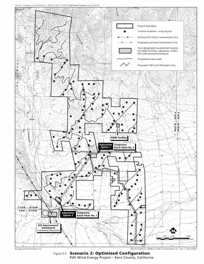
Scenario 2: Optimized Configuration. Wind turbines would be placed at strategic locations within the areas incorporating WE Combining District as depicted in Figure 3-3 to maximize the capture of wind energy as determined by wind optimizing software programs. This figure illustrates this layout with a hypothetical layout of 1.5 MW turbines. Other turbine sizes would use slightly different spacing.
Infrastructure locations as evaluated in this EIR for each scenario are depicted in Figures 3-2 and 3-3. The WE Combining District has a
County of Kern Chapter 3. Project Description
Draft EIR September 2007 PdV Wind Energy Project 3-14 002147.EX09.01
development standard requiring the applicant to provide a detailed plot plan (Section 19.64.130) that depicts the final location of all proposed infrastructure. Prior to the issuance of any construction permits, Kern County would review the Detailed Plot Plan for conformance with WE Combining District requirements as well as the project site’s constraint map (see Figure 3-1) and mitigation measures adopted as part of this environmental review process.
Infrastructure Siting Setbacks and Constraints The final siting of the proposed infrastructure, as presented on the detailed plot plan, would be required to conform to the siting setbacks and constraints described below.
Comply with Section 19.08.160(B)(1) (Interpretations and General Standards – Height of Structures) of the Kern County Zoning Ordinance, which limits the heights of all structures in the proposed project site to 400 feet above ground level.
Comply with the setback requirements specified in Section 19.64.140 (WE Combining District – Development Standards and Conditions) of the Kern County Zoning Ordinance:
19.64.140.F.1 Setback Where Adjacent Parcels Contain Less Than Forty (40) Acres. A minimum wind generator setback of two (2) times the overall machine height (measured from grade to the top of the structure, including the uppermost extension of any blades) or five hundred (500) feet, whichever is less, shall be maintained from exterior project boundaries where the project site is adjacent to existing parcels of record that contain less than forty (40) acres and are not zoned WE.
The Planning Director may allow a reduction in this setback, not to exceed a minimum setback of one (1) times the overall machine height (measured from grade to the top of the structure, including the uppermost extension of any blades) if a letter of consent from the owner(s) of record of adjacent parcels is filed with the Kern County Planning Department.
19.64.140.F.2 Setback Where Adjacent Parcels Contain Forty (40) Acres or More. A minimum wind generator setback one and one-half (1 1/2) times the overall machine height (measured from grade to the top of the structure, including the uppermost extension of any blades) or five hundred (500) feet, whichever is less, shall be maintained from all exterior project boundaries.

Figure 3-2 Scenario 1: Array ConfigurationPdV Wind Energy Project – Kern County, California
Ecology and Environment, Inc. 002147.EX09.01.u2(BW).ai (2007 Corp Archives CD - Vol 1) 05/21/2007
º
º
º
º
º
º
º
N0 2,500 5,0001,250
Feet
SubstationOption 2
••
••
••
••
••
•
•
SCE Interconnect/Switchyard
(Cottonwind Substation)
SubstationOption 1
O&M Facility
TemporaryBatch Plant No. 1
T9N – R15WT9N – R15WT10N – R15WT10N – R15W
T9
N – R
15
WT
10N
– R15
WT
10N
– R16
WT
10N
– R15
W
Existing SCE electric transmission line
Proposed overhead transmission line
Project boundary
Yard designated as potential locationfor O&M facilities, substation, and/orSCE interconnect/switchyard
• •
Proposed access roads
º º
Turbine locations - array layout
Sources: 1) Sapphos Environmental Inc., 2006; 2) USGS 1:24,000 Tylerhorse Canyon quad (reduced)
TemporaryBatch Plant No. 2
Proposed 12kV and fiberoptic lines

N0 2,500 5,0001,250
Feet
Figure 3-3 Scenario 2: Optimized ConfigurationPdV Wind Energy Project – Kern County, California
Ecology and Environment, Inc. 002147.EX09.01.v2(BW).ai (2007 Corp Archives CD - Vol 1) 05/21/2007
Sources: 1) Sapphos Environmental Inc., 2006; 2) USGS 1:24,000 Tylerhorse Canyon quad (reduced)
••
••
••
••
••
•
•
º
º
º
º
º
º
º
SubstationOption 2
TemporaryBatch Plant No. 1
SubstationOption 1
O&M Facility
TemporaryBatch Plant No. 2
••
••
••
••
••
•
•
T9N – R15WT9N – R15WT10N – R15WT10N – R15W
T9
N – R
15
WT
10N
– R15
WT
10N
– R16
WT
10N
– R15
W
Existing SCE electric transmission line
Proposed overhead transmission line
Project boundary
Yard designated as potential locationfor O&M facilities, substation, and/orSCE interconnect/switchyard
• •
Proposed access roads
º º
Turbine locations - array layout
SCE Interconnect/Switchyard
(Cottonwind Substation)
Proposed 12kV and fiberoptic lines

County of Kern Chapter 3. Project Description
Draft EIR September 2007 PdV Wind Energy Project 3-19 002147.EX09.01
The Planning Director may allow a reduction or waiver of this setback requirement in accordance with both of the following provisions:
a. The project exterior boundary is a common property line between two (2) or more approved wind energy projects or both properties are located within the WE District; and
b. The property owner of each affected property has filed a letter of consent to the proposed setback reduction with the Planning Director.
19.64.140.F.3 Setback from Off-site Residence(s) on Adjacent Parcels. In all cases, regardless of parcel area, a minimum wind generator setback of one and one-half (1 1/2) times the overall machine height (measured from grade to the top of the structure, including the uppermost extension of any blades) or five hundred (500) feet, whichever is greater, shall be maintained from any off-site residence.
The Planning Director may allow a reduction in this setback, not to exceed a minimum setback of one (1) times the overall machine height, if a letter of consent from the owner(s) of record of the adjacent parcel is filed with the Planning Director.
19.64.140.F.4 Project Interior Wind Generator Spacing. Wind generator spacing within the project boundary shall be in accordance with accepted industry practices pertaining to the subject machine.
19.64.140.F.5 Setback from On-site Residences and Accessory Structures Designed for Human Occupancy. A minimum wind generator setback of one (1) times the overall machine height (measured from grade to the top of the structure, including the uppermost extension of any blade) shall be maintained from any on-site residence or accessory structure designed for human occupancy.
19.64.140.F.6 Setback from Public Highways and Streets, Public Access Easements, Public Trails, and Railroads. A minimum wind generator setback of one and one-half (1 1/2) times the overall machine height (measured from grade to the top of the structure, including the uppermost extension of any blade) shall be maintained from any publicly maintained public highway or street. A
County of Kern Chapter 3. Project Description
Draft EIR September 2007 PdV Wind Energy Project 3-20 002147.EX09.01
minimum wind generator setback of one (1) times the overall machine height shall be maintained from any public access easement or railroad right-of-way. A minimum wind generator setback of one hundred fifty (150) feet shall be maintained from the outermost extension of any blade to any public trail, pedestrian easement, or equestrian easement.
Be installed to avoid sensitive resources and hazard zones as depicted on the constraints map (see Figure 3-1) and/or as described through this EIR, unless otherwise approved by Kern County.
Only be installed within the area surveyed for environmental resources (including areas surveyed during preconstruction surveying) as described in the methodology section for each resource section throughout this EIR and in the technical reports provided in the appendices.
Be installed such that the area of impact and extent of impacts on sensitive resources is no greater than that evaluated in this EIR.
While the constraints map provides an overview of the constraints the applicant would consider while finalizing the project design, the County will require additional site-specific maps to confirm that there are no environmental impacts associated with the final layout of project facilities that are not already identified in this EIR, particularly where these facilities vary from the locations assessed in this EIR.
Wind Turbines The project would use turbines ranging from 1 to 3 MW and would involve the installation of between 100 and 300 turbines, depending on the model used. Models available include 1.5, 2.0, 2.1, 2.3, 2.4, and 3.0 MW turbines. All turbine models would be a three-bladed and upwind design. Upwind design turbines are equipped with computers that would automatically turn the nacelle into the wind, placing the generator and tower behind the blades. A description of each of the primary wind turbine components is provided in the following sections. A typical schematic of wind turbines is provided in Figure 3-4. All turbines would be less than 400 feet with the blade at the uppermost position (12 o’clock). The shortest tower with the blade at the uppermost position would be the 1 MW Mitsubishi MWT-1000A turbine at 327 feet, and the tallest would be the 3 MW Vestas V90
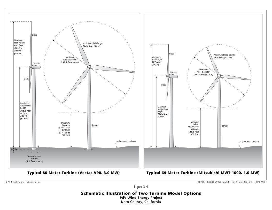
Figure 3-4
Schematic Illustration of Two Turbine Model OptionsPdV Wind Energy ProjectKern County, California
Typical 80-Meter Turbine (Vestas V90, 3.0 MW)
©2006 Ecology and Environment, Inc.
Maximum blade length:96.8 feet (29.5 m)
Maximumturbine hubheight:226.4 feet(69 m)
Maximumtotal height:327 feet(99.7 m)
Tower
Nacelle
Blade
Blade
Maximumrotor diameter:
201.4 feet (61.4 m)
Typical 69-Meter Turbine (Mitsubishi MWT-1000, 1.0 MW)
Minimumblade to
ground leveldistance:
125.6 feet(38.3 m)
Maximum blade length:144.4 feet (44 m)
Maximumturbine hubheight:255.6 feet(77.9 m)aboveground
Maximumtotal height:400 feet(121.9 m)aboveground
Tower
Ground surfaceGround surface
Nacelle
Blade
Blade
Maximumrotor diameter:
295.3 feet (90 m)
Tower diameterat base:
13.1 feet (3.98 m)
Minimumblade to
ground leveldistance:
~111.1 feet(33.9 m)
002147.EX09.01.p2(BW).ai (2007 Corp Archives CD - Vol 1) 03/05/2007
6.9 ft.

County of Kern Chapter 3. Project Description
Draft EIR September 2007 PdV Wind Energy Project 3-23 002147.EX09.01
turbine at 406.9 feet. For each Vestas V90 unit, a deeper foundation would be excavated and a portion of the tower would be installed below ground level, as shown in Figure 3-4, to comply with the 400-foot height limit. Tower Each wind turbine would be supported by a hollow, tubular steel tower that also houses the electric cable that transports energy from the generator to the transformer at the base of the tower. Turbine tower heights would be between 226.4 feet for the Mitsubishi MWT-1000A and 262.5 feet for the Vestas V90, as illustrated in Figure 3-4. Maintenance and other personnel would be able to access the tower through a steel door at the base of the tower. A ladder within the tower would provide personnel access to the equipment in the nacelle. A computerized control cabinet would be located inside and at the base of the tower. Both the door and control cabinet would be locked to prevent unauthorized access. The towers would not have external stairways or other external equipment, thus eliminating perching opportunities for birds. The towers would be painted a nonreflective, unobtrusive color or have a nonreflective surface. Rotor Blades Each wind turbine has three rotor blades, which generate energy through their rotation. The rotor blades are attached to a central hub at the top of the tower and to the turbine generator within the nacelle where the energy is transferred. The blade lengths would vary based on the turbines used. The blade length for the Mitsubishi MWT-1000A would be 100.7 feet, and the blade length for the Vestas V90 would be 144.4 feet. The maximum tip height (tower plus blade length at the uppermost position) of all turbines would not exceed 400 feet. The blades would be composed of laminated fiberglass or a fiberglass composite and would have a smooth outer surface. The blades would be painted a nonreflective, unobtrusive color or have a nonreflective surface. Nacelle The nacelle is a rectangular box located directly behind the central hub. The nacelle would contain the generator, generator control system, and other equipment. The project would use the “upwind” turbine design in which, through the aid of computers, the nacelle automatically turns into the wind to place the generator and tower behind the blades. The nacelle is sized to provide sufficient room for maintenance personnel to work on the machinery inside it. The exterior surface of the nacelle is
County of Kern Chapter 3. Project Description
Draft EIR September 2007 PdV Wind Energy Project 3-24 002147.EX09.01
constructed of fiberglass. When performing maintenance, personnel would access the nacelle from a steel ladder inside the tower. Access to the nacelle from the tower would be from a hatch at the base of the frame; maintenance could be carried out when the nacelle is closed. Braking System To prevent rotors from dislocating from the turbine, each of the turbines would be equipped with a braking system that controls the rotors. In the event of malfunctions, the automatic breaking system would shut down the turbines. As a second safety measure, personnel could stop, start, and rotate each of the turbines parallel to the prevailing wind direction using the control panel inside the nacelle or from the bottom of the tower. To avoid operating the turbine while a maintenance worker is inside the nacelle, switches at the top of the tower would prevent service personnel at the bottom from operating certain systems. Each turbine could also be controlled from the on-site O&M building. Off-site remote control would also be possible. Safety Lighting The project would be constructed and operated in accordance with Federal Aviation Administration (FAA) rules for structural lighting, locations, and height. Safety lighting would be installed on the exterior of some of the nacelles in compliance with FAA rules. Specific requirements for the project would be developed in conjunction with the FAA based on the turbine heights and site-specific aviation conditions. On recent wind projects, white flashing lights were used during the daytime and red flashing lights were used at night to warn aviators away from the area. Lights were not required on every wind turbine; instead, they were spaced every 1,000 feet and at the ends of turbine strings. The FAA recently changed its guidance for wind turbine lighting and now requires only synchronized red flashing lights at night (and none during daylight hours). Lighting for the project would be consistent with all FAA requirements. Lightning Protection System For protection from potential lightning strikes, each wind turbine, including the rotor blades, would be equipped with a lightning protection system. The lightning protection system would be connected to an underground grounding arrangement to facilitate lightning flowing safely to the ground. In addition, all equipment, cables, and structures comprising the wind turbines would be connected to a metallic project-wide grounding network.
County of Kern Chapter 3. Project Description
Draft EIR September 2007 PdV Wind Energy Project 3-25 002147.EX09.01
Turbine Foundation/Pad
The wind turbines would stand on steel-reinforced concrete foundations designed for the specific subsurface soil conditions at each individual turbine site. Foundation types may include an inverted T-type foundation, a dead-man type foundation, or a pile type foundation. The foundation design would be selected based on site-specific conditions identified and assessed during geotechnical studies and the design engineer’s requirements. The belowground portion of the tower foundation could measure up to approximately 50 feet by 50 feet. The foundation would extend approximately 1 foot above the ground surface. The aboveground disturbance associated with installation of the turbine foundation, including a larger area around the foundation called the turbine pad, would be approximately 150 feet by 150 feet. This area would be cleared and compacted for use during construction and O&M. The tower pad area would provide an area for construction staging, the tower foundation, the electrical transformer to be installed at the base of the tower, and a 10-foot-wide fuel break encircling the wind towers. Assuming the worst-case scenario installation of 300 turbines, the tower foundation/pad areas would disturb up to approximately 155 acres for either turbine configuration scenario. This area would be permanently disturbed and would be treated with gravel or caliche to stabilize the area where necessary.
Power Collection System The power collection system consists of underground, 34.5 kV electrical feeder lines that would transport energy produced by the turbines to a new PdV substation. Initially, power generated by the turbines would be fed down the tower through cables connected to a pad-mounted electrical transformer located adjacent to and outside the tower base. From the transformer, power would be transferred to the underground feeder lines. Junction boxes would be located at various locations along the underground feeder lines to facilitate power collection. The communication cable to which the Supervisory Control and Data Acquisition (SCADA) system is linked would be installed in the same trench as the electrical feeder lines, separated by a layer of fill. This system would allow the applicant to monitor project facilities during operation from remote locations and immediately identify any operational issues. All on-site electrical feeder lines associated with the wind turbines would be installed underground within the footprint of disturbance for

County of Kern Chapter 3. Project Description
Draft EIR September 2007 PdV Wind Energy Project 3-26 002147.EX09.01
the proposed access roads or within the 150-foot by 150-foot turbine foundation/pad area, with the exception of tie-ins to utility-type transmission poles, towers, and lines. Based on the installation of 300 turbines (worst-case scenario), approximately 41.25 miles of underground electric feeder line would be installed for either scenario. If fewer turbines were installed, the length of electric feeder line would be reduced. The disturbance for the approximately 2-foot-wide trench where the underground cable would be installed would be approximately 15 feet wide. Therefore, the area impacted by the power collection system, including transformers and junction boxes, would be up to approximately 75 acres regardless of which scenario or turbine were used. Since this trench for the power collection system would be installed within areas disturbed by the turbine foundation/pads and/or access roads, the 75 acres of disturbance are accounted for within the area of impact for those features. Where it is impracticable to place collection lines underground due to terrain (for example, steep slopes or canyons) or other factors, overhead lines would be installed on wooden poles, consistent with all applicable County codes. The power collection system for each turbine configuration option is shown in Figures 3-2 and 3-3.
PdV Project Substation The project would include construction of a new PdV substation that would collect all power generated by the turbines and step it up from 34.5 kV to 220 kV. Power from the PdV substation would then be transported via an overhead transmission line to the proposed SCE interconnect/switchyard (also known as the “Cottonwind substation,” described below), where the power would be delivered to the existing 220 kV SCE regional transmission line and/or ultimately a 500 kV transmission system, as described in the SCE Tehachapi Renewable Transmission Project system upgrades (discussed in Section 3.10) and the CAISO Regional Transmission Plan. Equipment at the PdV substation would include transformers, breakers, and associated equipment. The PdV substation facility would house the power generation control and relaying equipment, station batteries, and SCADA system and would be remotely operated and periodically maintained (but would not be manned). The PdV substation would be cleared, graded, and graveled. An 8-foot tall, chain-link security fence would be installed around the perimeter.
County of Kern Chapter 3. Project Description
Draft EIR September 2007 PdV Wind Energy Project 3-27 002147.EX09.01
Construction and operation of the PdV substation would permanently disturb approximately 12.4 acres. This EIR analyzes potential impacts of locating the PdV substation in either Section 27 or Section 33. The PdV project includes two substation location options. Option 1 is in Section 27 and Option 2 is in Section 33. The substation location options are depicted in Figures 3-2 and 3-3. Power would be transmitted from the wind turbines through the underground power collection system and increased from 34.5 kV to 220 kV at the project substation. From the substation, the power would be transmitted through a 220 kV on-site electrical line (approximately 2 miles from Option 1 or approximately 2,500 feet from Option 2) to the SCE interconnection (Cottonwind substation) in Section 4. The line would be between 90 to 120 feet tall on tubular or lattice-style towers and would be similar in height to existing SCE 220/500 kV transmission lines. If Option 2 is selected, the site would house one or both of the substations and a short 220 kV line would be built from the yard to the SCE line corridor.
Overhead Transmission Line To transport energy generated by the project to SCE’s regional transmission line, an overhead power transmission line would be constructed from the PdV substation to the proposed SCE Cottonwind substation, which would connect to the regional transmission line (see Figures 3-2 and 3-3). The SCE Cottonwind substation would be located in Section 4 under Option 1 or in Section 33 under Option 2. The length of the transmission line would depend on final siting of the PdV substation. If the PdV substation is located in Section 27, the overhead power line would be 10,200 feet long. If the PdV substation is located in Section 33, the overhead power line would be 2,500 feet long. Both lines would cross similar habitat. This EIR considers the worst-case scenario of constructing a 10,200-foot long overhead transmission line to assess the project’s impacts. To support the overhead transmission line, up to 37 power poles would be installed at intervals of 300 feet. Each power pole would disturb an approximately 5-foot by 10-foot area, and a 15-foot-wide access road would be constructed to provide access to the towers. Therefore, the overhead transmission line would permanently affect up to 4 acres.
SCE Cottonwind Substation The proposed SCE interconnect/switchyard facility, known as the Cottonwind substation, would serve to connect the short transmission line from the project substation to the existing SCE 220 kV and/or
County of Kern Chapter 3. Project Description
Draft EIR September 2007 PdV Wind Energy Project 3-28 002147.EX09.01
ultimately 500 kV transmission lines that cross the site (the transmission lines are described in the SCE Tehachapi Renewable Transmission Project system upgrades [discussed in Section 3.10] and the California ISO Regional Transmission Plan). Construction and operation of the facility would permanently affect an approximately 20-acre area, including a 10-foot-wide fuel break around the perimeter. The Cottonwood substation would probably consist of main power transformers, as required for 220 kV to 220 kV/500 kV interconnection, buswork, metering, breakers, switches, a control building, station power, relays, grounding, foundations, steel structures, fencing and aggregate. SCE would require the 220kv Cottonwind switching station to facilitate the project’s early interconnection into the transmission system prior to system upgrade (described under “Related Projects” in Section 3.8.2.) The PdV project has offered the land in Section 4 (with an alternate location in Section 33) as a location for the SCE facility. The proposed location for the SCE Cottonwood substation evaluated in this EIR is depicted in Figures 3-2 and 3-3.
SCE Regional Special Protection Scheme for Early Interconnection
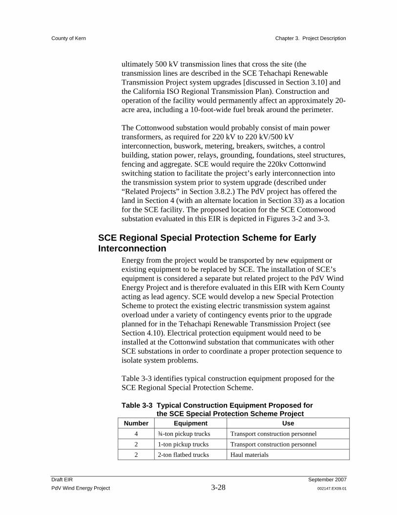
Energy from the project would be transported by new equipment or existing equipment to be replaced by SCE. The installation of SCE’s equipment is considered a separate but related project to the PdV Wind Energy Project and is therefore evaluated in this EIR with Kern County acting as lead agency. SCE would develop a new Special Protection Scheme to protect the existing electric transmission system against overload under a variety of contingency events prior to the upgrade planned for in the Tehachapi Renewable Transmission Project (see Section 4.10). Electrical protection equipment would need to be installed at the Cottonwind substation that communicates with other SCE substations in order to coordinate a proper protection sequence to isolate system problems. Table 3-3 identifies typical construction equipment proposed for the SCE Regional Special Protection Scheme. Table 3-3 Typical Construction Equipment Proposed for
the SCE Special Protection Scheme Project Number Equipment Use
4 ¾-ton pickup trucks Transport construction personnel 2 1-ton pickup trucks Transport construction personnel 2 2-ton flatbed trucks Haul materials
County of Kern Chapter 3. Project Description
Draft EIR September 2007 PdV Wind Energy Project 3-29 002147.EX09.01
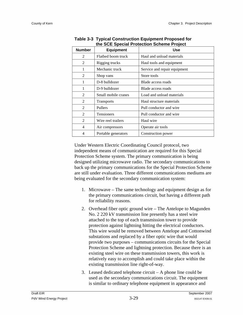
Table 3-3 Typical Construction Equipment Proposed for the SCE Special Protection Scheme Project
Number Equipment Use 2 Flatbed boom truck Haul and unload materials 2 Rigging trucks Haul tools and equipment 1 Mechanic truck Service and repair equipment 2 Shop vans Store tools 1 D-8 bulldozer Blade access roads 1 D-9 bulldozer Blade access roads 2 Small mobile cranes Load and unload materials 2 Transports Haul structure materials 2 Pullers Pull conductor and wire 2 Tensioners Pull conductor and wire 2 Wire reel trailers Haul wire 4 Air compressors Operate air tools 4 Portable generators Construction power
Under Western Electric Coordinating Council protocol, two independent means of communication are required for this Special Protection Scheme system. The primary communication is being designed utilizing microwave radio. The secondary communications to back up the primary communications for the Special Protection Scheme are still under evaluation. Three different communications mediums are being evaluated for the secondary communication system:
1. Microwave – The same technology and equipment design as for the primary communications circuit, but having a different path for reliability reasons.
2. Overhead fiber optic ground wire – The Antelope to Magunden No. 2 220 kV transmission line presently has a steel wire attached to the top of each transmission tower to provide protection against lightning hitting the electrical conductors. This wire would be removed between Antelope and Cottonwind substations and replaced by a fiber optic wire that would provide two purposes – communications circuits for the Special Protection Scheme and lightning protection. Because there is an existing steel wire on these transmission towers, this work is relatively easy to accomplish and could take place within the existing transmission line right-of-way.
3. Leased dedicated telephone circuit – A phone line could be used as the secondary communications circuit. The equipment is similar to ordinary telephone equipment in appearance and
County of Kern Chapter 3. Project Description
Draft EIR September 2007 PdV Wind Energy Project 3-30 002147.EX09.01
function but has a wider bandwidth to accommodate the complexity of the communication. Using this medium would not require construction of any additional poles or lines beyond what would be required to provide telephone service to the site. This option would traverse existing roads in the project area and would result in no further areas of disturbance.
SCE would construct the Cottonwind substation (switchyard) in Section 4 of the southwestern portion of the wind energy project site. The associated facilities for the Cottonwind substation (switchyard) include transmission line, station light and power, and telecommunication channels. Two telecommunications channels are required to support the proposed Cottonwind substation and the special protection scheme (SPS) required to protect the existing electrical transmission system against overload under a variety of contingency events. The first proposed channel requires installation of 22.3 miles of new fiber optic cable between the existing Rosamond substation, proposed Cottonwind substation, and SCE’s existing Antelope substation. Most of the 22.3 miles would utilize existing poles, requiring only the addition of a single cable to the existing six poles. The second proposed channel would require installation of a 110-foot-high microwave tower and new microwave telecommunications system for communication between Cottonwind and Antelope substations.
Most of the proposed fiber optic route follows two-lane paved roads. A 12- to 15-foot shoulder exists on either side of the roads. The shoulder consists of disturbed land and is mostly dirt and gravel. An additional two miles of the route would be adjacent to a graded but unpaved road along 150th Street West and Gaskell Road. Another two miles of the route would cross undeveloped lands and terminate at the Antelope substation. The proposed fiber optic route is described in three segments. The first segment would travel west along Rosamond Boulevard from the Rosamond substation on 60th Street West and Rosamond Boulevard to 150th Street West (see Figure 3-6 at the end of the Project Description). An existing wood pole transmission line on the north side of Rosamond Boulevard along this entire segment has wood poles approximately 60 feet tall and contains six lines (three 12kV and three 66kV). No poles exist on the south side of Rosamond Boulevard. The Rosamond substation abuts Rosamond Boulevard at 60th Street West. The Willow Springs International Speedway sits north of Rosamond Boulevard between 70th and 80th Streets West.

County of Kern Chapter 3. Project Description
Draft EIR September 2007 PdV Wind Energy Project 3-31 002147.EX09.01
The proposed new construction poles would be 25 to 35 feet tall, which is considerably shorter then the existing 60-foot wood poles across the street. The proposed poles would be made of wood. Rosamond Boulevard, although a major traffic artery in the community of Rosamond, is not heavily traveled east of 60th Street West, which is the starting point of the proposed construction.
The second segment of the proposed fiber optic route (see Figure 3-6 at the end of the Project Description) would require new construction because no poles exist on either the north or south side of Rosamond Boulevard from 150th Street West to 170th Street West, except for wood poles on the north side of Rosamond Boulevard from 150th Street West to 155th Street West. SCE would construct the new 25- to 35-foot wood poles on either the north or south side of Rosamond Boulevard to 170th Street West, where the route would then continue north on 170th Street West to the project site.
The third segment of the proposed fiber optic route (see Figure 3-6 at the end the of Project Description) would use an existing wood pole transmission line that runs southeast from 150th Street West and Rosamond Boulevard to the Antelope substation on Avenue J and 100th Street West. SCE would add the fiber optic line to the existing lines along this existing route, which terminates at the Antelope substation. From Rosamond Boulevard and 150th Street West, the existing line spurs south two miles. The line then turns east on Gaskell Road for one mile. The line then proceeds south at 140th Street West for approximately four miles. At the intersection of 140th Street West and Avenue D, the line runs east for approximately four miles and then runs south down 110th Street West for approximately 4.5 miles. At this point on 110th Street West, the existing line meets and parallels the SCE 250kV transmission line, which transects both the project site and the Antelope substation. There is no graded road for this diagonal swath and therefore no streets by which to identify this segment of the line. However, right before the diagonal meets Avenue J at approximately 100th Street West, the existing wood pole line breaks from the parallel path and jumps due east onto private property for approximately 300 feet, where it then turns due south for another 300 feet and crosses Avenue J and terminates at Antelope substation.
Avoidance and Minimization Measures for the SCE Regional Special Protection Scheme In order to avoid and minimize any potential impacts on the environment, the SCE Regional Special Protection Scheme has incorporated the following measures, as applicable, into the communications system design:
County of Kern Chapter 3. Project Description
Draft EIR September 2007 PdV Wind Energy Project 3-32 002147.EX09.01
Agricultural Resources Following the completion of construction activities, all areas of
temporary disturbance will be returned to preconstruction conditions and uses.
SCE’s communications system activities will occur under the oversight of the California Public Utilities Commission (CPUC), and appropriate land uses will be restored per the CPUC requirements.
Air Quality Reformulated fuels, emulsified fuels, catalyst and filtration
technologies, cleaner engine re-powers, and new alternative-fueled trucks will be used.
Idling of engines will be minimized; engines will be turned off when not in use, where applicable, considering engine manufacturer’s specifications, construction procedures, and safety concerns. Equipment will be maintained and properly tuned.
SCE will implement measures to control dust in accordance with local air district.
The hours of operation of heavy-duty equipment and/or the amount of equipment in use will be limited, where feasible.
All active construction areas will be watered, as needed.
All trucks hauling soil, sand, and other loose materials will be covered or maintain at least two feet of freeboard.
All unpaved access roads, parking areas, and staging areas at construction sites will be either paved, have water applied three times daily, or have nontoxic soil stabilizers applied.
All paved access roads, parking areas, and staging areas at construction sites will be swept daily (with water sweepers).
Streets will be swept daily (with water sweepers) daily if visible soil material is carried onto adjacent public streets.
Procedures to be implemented at all construction sites greater than four acres:
– Hydroseed or apply nontoxic soil stabilizers to inactive construction areas (previously graded areas inactive for 10 days or more).
– Enclose, cover, and water twice daily or apply nontoxic soil binders to exposed stockpiles (e.g., dirt and sand).
County of Kern Chapter 3. Project Description
Draft EIR September 2007 PdV Wind Energy Project 3-33 002147.EX09.01
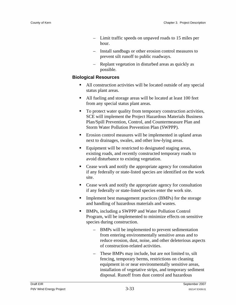
– Limit traffic speeds on unpaved roads to 15 miles per hour.
– Install sandbags or other erosion control measures to prevent silt runoff to public roadways.
– Replant vegetation in disturbed areas as quickly as possible.
Biological Resources All construction activities will be located outside of any special
status plant areas.
All fueling and storage areas will be located at least 100 feet from any special status plant areas.
To protect water quality from temporary construction activities, SCE will implement the Project Hazardous Materials Business Plan/Spill Prevention, Control, and Countermeasure Plan and Storm Water Pollution Prevention Plan (SWPPP).
Erosion control measures will be implemented in upland areas next to drainages, swales, and other low-lying areas.
Equipment will be restricted to designated staging areas, existing roads, and recently constructed temporary roads to avoid disturbance to existing vegetation.
Cease work and notify the appropriate agency for consultation if any federally or state-listed species are identified on the work site.
Cease work and notify the appropriate agency for consultation if any federally or state-listed species enter the work site.
Implement best management practices (BMPs) for the storage and handling of hazardous materials and wastes.
BMPs, including a SWPPP and Water Pollution Control Program, will be implemented to minimize effects on sensitive species during construction.
– BMPs will be implemented to prevent sedimentation from entering environmentally sensitive areas and to reduce erosion, dust, noise, and other deleterious aspects of construction-related activities.
– These BMPs may include, but are not limited to, silt fencing, temporary berms, restrictions on cleaning equipment in or near environmentally sensitive areas, installation of vegetative strips, and temporary sediment disposal. Runoff from dust control and hazardous

County of Kern Chapter 3. Project Description
Draft EIR September 2007 PdV Wind Energy Project 3-34 002147.EX09.01
materials will be retained on the construction site and prevented from flowing into the environmentally sensitive areas.
During construction operations, the number of access routes, number and size of staging areas, and the total area of the proposed project activity will be limited to the minimum necessary.
– Routes and boundaries will be clearly demarcated. Movement of heavy equipment to and from the project site will be restricted to established roadways to minimize habitat disturbance.
– Project-related vehicles will observe a 20-mile-per-hour speed limit within construction areas, except on county roads and on state and federal highways.
– All heavy equipment, vehicles, and supplies will be stored at the designated staging area at the end of each work period.
– No staging areas will be located within 200 feet of aquatic habitat.
During construction operations, stockpiling of construction materials, portable equipment, vehicles, and supplies will be restricted to designated construction staging areas and be outside of the environmentally sensitive areas.
– SCE will ensure that contamination of habitat does not occur during such operations.
– All workers will be informed of the importance of preventing spills and the appropriate measures to take should a spill occur.
Cultural Resources The contractor will be required to immediately cease ground-
disturbing activities within 100 feet of a cultural resources discovery and immediately notify SCE.
In the instance of a possible discovery, the contractor will flag the area for easily visible identification while also protecting the discovery from vandalism, looting, or further disturbance of any kind.
SCE will contact a qualified archeologist to evaluate the find, and will coordinate with applicable agencies, including the CPUC.
County of Kern Chapter 3. Project Description
Draft EIR September 2007 PdV Wind Energy Project 3-35 002147.EX09.01
The qualified archeologist will determine whether:
– The resource can be avoided with avoidance measures and impacts on cultural resources have not occurred, in which case the PdV Wind Energy Project could proceed with implementation of avoidance measures and only after approval by the CPUC; or
– The resource cannot be avoided or it has already been impacted by construction, in which case an assessment of its significance will be conducted in compliance with state law.
If the discovery includes human remains, the qualified archeologist will notify the CPUC and the County coroner to assist in determining the significance of the remains.
If the human remains are determined to be Native American, the most likely descendant will be contacted within 24 hours and provided the opportunity to visit the site and participate in determining appropriate treatment, which may include:
– Preserving the remains in place and avoiding further impact (preferred method); or
– Developing a plan for the recovery and documentation of the remains and any associated grave goods.
Geological Resources As part of engineering and design for the communications
system, SCE will evaluate hazards associated with expansive soils and will implement engineering and design measures as part of the project description, as necessary, to offset any potential hazards.
A Project-specific SWPPP will be implemented to reduce erosion from Project construction and operation activities.
Hazardous Materials SCE will implement the Project Hazardous Materials Business
Plan/Spill Prevention, Control, and Countermeasure Plan and SWPPP.
Equipment will be restricted to designated staging areas, existing roads, and recently constructed temporary roads.
BMPs will be implemented for the storage and handling of hazardous materials and wastes.
County of Kern Chapter 3. Project Description
Draft EIR September 2007 PdV Wind Energy Project 3-36 002147.EX09.01
Water Quality Temporary work areas (lay down areas, and staging areas) will
be placed to avoid direct impacts on streams and wetlands.
BMPs will be implemented for erosion control.
During construction, vegetation removal and grading will be limited to the minimum area necessary and restricted only to areas required for construction.
Erosion control structures will be placed between disturbed soil and drainage structures or areas prior to the start of the rainy season.
The grading, construction, and drainage of roads will be carried out to maintain any downstream water quality.
Noise Care of Equipment – Equipment engines will be covered, and
SCE will ensure that mufflers are in good working condition. This measure can reduce equipment noise by 5 to 10 dBA (U.S. Environmental Protection Agency 1971).
Restricted Work Hours – Noise-generating construction activities will be limited to the following hours: between 5:30 a.m. and as late as 9:00 p.m. Monday through Saturday. If required to meet critical schedule milestones, construction may also occur between 7:00 a.m. to 6:00 p.m. on Sundays.
Equipment Location – All stationary equipment such as compressors and welding machines will be located away from noise receptors to the extent practicable.
Pneumatic Tools – Pneumatic tools to be used within 1,500 feet of a residence will have an exhaust muffler on the compressed air exhaust. This will be included in the construction specifications.
Helicopter landing/staging areas will be sited along the existing alignment, away from residences.
Public Services SCE will implement a Grass Fire Control Plan for use during
construction that will sufficiently mitigate increased fire risk.
To avoid and minimize potential impacts on existing medical and emergency care services, SCE will develop and follow a Health and Safety Plan.
County of Kern Chapter 3. Project Description
Draft EIR September 2007 PdV Wind Energy Project 3-37 002147.EX09.01
Safety SCE requires that all equipment be grounded to capture induced
voltage from nearby active circuits. Ground rods will also be used for reel puller and bullwheel tensioner trucks and any equipment near an energized conductor. Grounding equipment will be connected to these ground rods during construction and will be disconnected when the line is restored to service.
To prevent other work-related accidents and injuries, each SCE work crew will prepare a specific emergency response plan that is tailored to the circumstances of their work. The specific plans will include local emergency contact information lists on sign boards attached to crew vehicles and designated emergency routes in the event of an industrial injury.
SCE will require that vehicles and equipment primarily use roads to access the transmission tower sites. Project personnel will be directed to park away from dry vegetation and will be required to carry water, shovels, and fire extinguishers in times of high fire hazard.
SCE will prohibit trash burning and restrict smoking to cleared areas.
Transportation Traffic control measures will be implemented as required by
permitting authorities to reduce potential impacts on local traffic patterns.
To avoid impacts to traffic from construction-related traffic, construction-worker carpooling will be organized and encouraged to the extent feasible. Parking will be allowed only in Project-approved areas to prevent impacts on existing parking capacity.
SCE will obtain encroachment permits from the appropriate agency for any work within public right-of-ways.
Any damage to streets or roadways caused by SCE's project construction will be repaired or restored by SCE to preconstruction condition.
Regulation-sized vehicles will be used, except for specific construction equipment, which may haul oversized loads.
Anemometer Towers There are ten existing anemometer towers within the project site, each less than 400 feet tall. Anemometer towers gather data on wind

County of Kern Chapter 3. Project Description
Draft EIR September 2007 PdV Wind Energy Project 3-38 002147.EX09.01
resources and weather. This system is used to control and operate the wind plant and is connected into the grid and controlled by the CAISO. The anemometer towers would be connected to the O&M building via the SCADA system
Access Roads As described above, access to the project site would be from the corner of Rosamond Boulevard and north along 170th Street West to its terminus and would require an approximately 3.3-mile extension north to the southern boundary of the project site. Specifically, at the terminus of 170th Street West, the new road to be constructed would continue north approximately an additional 1.7 miles. At this point, the road would turn west for approximately 1,425 feet. The road would then turn north again for approximately 1,875 feet and intersect with the boundary of the project. The road would be designed in accordance with Kern County Roads Department standards. Two new bridges or box culvert-type structures would be constructed to Los Angeles Department of Water and Power and Kern County standards for two crossings of the Los Angeles Aqueduct. Existing access roads would be used to the extent feasible. Construction and operation of the project would also require the construction of approximately 41.6 miles (219,648 feet) of new, unpaved, 36-foot-wide access roads (16-foot-wide roads and 10-foot-wide shoulders) to serve the turbines and other facilities from the existing roads (see Figures 1-1 and 1-2). Therefore, construction of new roads for the project would affect approximately 181.6 acres. New access roads would be built in accordance with standard engineering practices and as required by County ordinances. A schematic of typical access road construction is provided in Figure 3-5. The final location of project access roads would depend on the final location of turbines and associated facilities. Where project access roads are required to cross dry washes, an appropriate crossing method would be used to minimize impacts on jurisdictional areas (see Section 4.8, “Hydrology and Water Quality”). Construction of the project access roads would not require a WE Combining District overlay. If any roads need to be elevated, it would be accomplished using compacted fill. All fill material would come from the project site. The fill material would be excess soil available from the turbine foundation excavation.
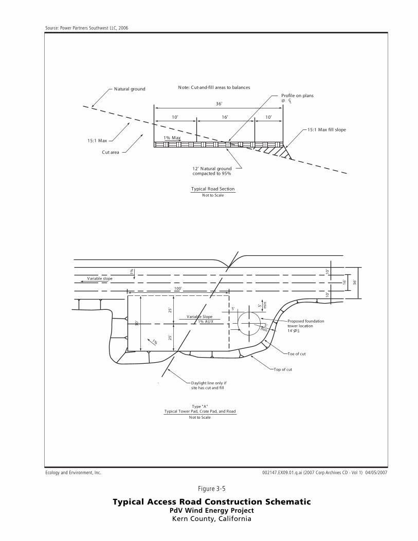
12' Natural groundcompacted to 95%
Typical Road SectionNot to Scale
15:1 Max fill slope
Natural ground
15:1 Max
Cut area
1% Max
Profile on plans@
Note: Cut-and-fill areas to balances
36'
10' 16' 10'
Variable slope
100'
5'
5' min
5'min
25'
25'
30'
1%
Variable Slope1% AUX
10'
10'
16'
36'
1%
Daylight line only ifsite has cut and fill
Top of cut
Toe of cut
Proposed foundationtower location14'
Type "A"Typical Tower Pad, Crate Pad, and Road
CL
Not to Scale
Figure 3-5
Typical Access Road Construction SchematicPdV Wind Energy ProjectKern County, California
Ecology and Environment, Inc.
Source: Power Partners Southwest LLC, 2006
002147.EX09.01.q.ai (2007 Corp Archives CD - Vol 1) 04/05/2007

County of Kern Chapter 3. Project Description
Draft EIR September 2007 PdV Wind Energy Project 3-41 002147.EX09.01
Concrete Batch Plant
The project would require the use of on-site temporary, portable concrete batch plants, under a conditional use permit, on site to provide concrete and materials for the turbine, transformer, PdV substation, and O&M building foundations. The concrete batch plants would operate between approximately 7:00 a.m. and 7:00 p.m., Monday through Saturday. Approximately 8 to 12 concrete batch plant operators and truck drivers would be employed. The concrete batch plants are anticipated to operate as needed for up to six months and would be removed after construction is complete. All remnant materials and debris would be hauled off site and disposed of at a certified location. The batch plants would be located and utilized at the designated yards and moved to various areas of the project site as required to minimize construction traffic.
Operations and Maintenance Building The project would involve construction of an approximately 0.1-acre (4,800-square-foot) O&M building, including a 10-foot-wide fuel break around the perimeter. Figures 3-2 and 3-3 illustrate the location of the O&M building for both turbine configuration options. The O&M building would be constructed to house the facility electronic controls and communications systems; provide storage for tools, maintenance supplies, and spare parts; and provide office, kitchen, and bathroom facilities for operations staff. The O&M building site would also provide parking space for employees, visitors, and equipment.
Staging Areas Staging of equipment and materials, and the office area would occur at the O&M building, PdV substation, SCE interconnect/switchyard (Cottonwind Substation), and two additional temporary staging areas. These areas are identified in Figures 3-2 and 3-3 as the location of the temporary concrete batch plants, but they may also be used for other staging needs. The area for these two yards is anticipated to be between 6 and 10.5 acres. The two staging areas would be restored following construction. Surface areas at the O&M building, PdV substation, and the SCE interconnect/switchyard that are not covered by a building would be treated to provide long-term stabilization (i.e., application of gravel or caliche).
Fencing Kern County’s fencing requirements for proposed wind developments can be found in Section 19.64.140(c) of the County Zoning Ordinance.

County of Kern Chapter 3. Project Description
Draft EIR September 2007 PdV Wind Energy Project 3-42 002147.EX09.01
As described in this section of the zoning ordinance, there are several options for fencing wind developments, including installing fencing around the perimeter, around each individual turbine, or around turbine rows. Fencing is specific to existing project site conditions. The WE Combining District fencing requirements provide that fencing may be waived for any portion of a project site where unauthorized access is precluded due to topographic conditions. The applicant proposes to use perimeter fencing to secure the project site. As proposed, new fencing would be installed only along portions of the eastern and southern border. The applicant is requesting that fencing not be installed along the northern perimeter because the existing terrain and rough topography of the Tehachapi Mountains north of the project site would limit access from the north. The remaining perimeter of the project site has existing agricultural fencing, except for portions of the eastern and southern boundary, where additional fencing would be installed. In total, up to approximately 180,000 linear feet (34 miles) of fencing would be installed with posts normally placed at 15-foot intervals. Therefore, installation of fencing would affect up to 0.3 acre of the site. The fence would be a minimum of four-feet high and constructed of four-strand barbed wire or materials of higher quality. Additional fencing at these locations would provide adequate site security. This fencing strategy would apply to both Scenario 1: Array Configuration and Scenario 2: Optimized Configuration assessed in this EIR.
Supporting Public Service Utilities Because of the remote location of the project area, there is no existing domestic water delivery system or community sewer system at the project site. If the applicant is unable to secure the use of an existing water source, the project may include installing a water well to support construction activities and long-term maintenance and operations. Water consumption is expected to be minimal, as the highest volume of use would be during the limited eight- to ten-month construction period and would drop off during operation, when only 10 to 16 on-site employees would require water. The project site is undeveloped and is not served by a community sewage system. Therefore, the project would require development of a septic system and leach line for O&M. The area affected by the septic system and leach line would be located within the area affected by the designated yards and/or PdV substation locations. The septic system and leach field would be constructed to comply with applicable requirements of the Kern County Environmental Health Department. Public services and utilities and services are discussed further in Section 4.13, “Public Services.”
County of Kern Chapter 3. Project Description
Draft EIR September 2007 PdV Wind Energy Project 3-43 002147.EX09.01
3.5.2 Circulation
The regional circulation system near the PdV Wind Energy Project consists of State Highway 58 and State Highway 14. The local circulation system near the project site consists of Rosamond Boulevard, 170th West Street, Tehachapi-Willow Springs Road, Backus Road, Mojave Tropico Road, Oak Creek Road, and Silver Queen Road These roads connect with smaller paved and dirt access roads. The project would involve the construction of a new private and public access road. The new public access road would extend approximately 3.3 miles north from the terminus of 170th West (north of Rosamond Boulevard), into the southernmost area of the project site in Section 2. Within the project site, the applicant proposes to construction new private gravel and dirt access roads as described under "Access Roads" in Section 3.5.1 above. A detailed discussion of circulation is provided in Section 4.15, “Transportation and Traffic.”
3.6 Entitlements Required Construction and operation of the project and related SCE Special Protection Scheme would require the following discretionary actions and approvals:
Amendment of Zone Map 216 and 233 to include the WE Combining District;
Approval of a conditional use permit for temporary batch plants;
FAA Determination of No Hazard to Air Navigation;
National Pollutant Discharge Elimination System (NPDES) Construction General Permit;
California Fish and Game Code Section 1600 et seq. permits (Streambed Alteration Agreements); and
Approval of a Permit to Construct (PTC) by the California Public Utilities Commission for the SCE Special Protection Scheme and Certificate of Public Convenience and Necessity (CPCN) for the Cottonwind substation.
3.7 Construction 3.7.1 Construction Sequence and Equipment
The project would generally be constructed in the following phases:

County of Kern Chapter 3. Project Description
Draft EIR September 2007 PdV Wind Energy Project 3-44 002147.EX09.01
Site preparation;
Construction of access roads and crane pads;
Installation of power collection system;
Installation of foundations;
Turbine installation;
Interconnection and PdV substation facility construction;
Electrical system upgrades; and
Final testing and turbine commissioning.
These construction phases and activities associated with each phase are described in the following sections. Construction of these phases may overlap. Table 3-4 lists typical construction equipment that would be used during construction.
Table 3-4: Typical Construction Equipment for Wind Plants Equipment Use
Bulldozer(s) Road and pad construction, PdV substation, O&M building Grader(s) Road and pad construction, PdV substation, O&M building Water trucks Compaction, erosion, and dust control Roller/compactor(s) Road and pad compaction Backhoe/trenching machine(s) Excavating trenches for underground utilities Truck-mounted drilling rig(s) Drilling tower foundations (holes for poles supporting overhead
lines, if needed) Concrete trucks and pumps Pouring tower and other structure foundations Conventional and small cranes Off-loading equipment on-site upon arrival Heavy and intermediate cranes Off-loading and erecting towers, nacelles, and rotors Cement and gravel haul trucks Hauling road and pad construction materials Semi-trailer trucks Delivering towers, blades, and other equipment Pickup trucks General use and hauling minor equipment Large and small cranes and terrain forklifts and equipment
Erecting towers, turbines, and blades to complete the wind turbine assembly
Four-wheeled all-terrain vehicles Access and underground electrical line installation Rough-terrain forklift Lifting equipment
3.7.2 General Grading Description
The project would involve grading of access roads, turbine crane pads, designated yards, and other work areas during project construction. Grading would affect up to 374 acres of land, of which 276.8 acres would be permanently disturbed and 117 acres would be temporarily disturbed during construction. Grading permits would be required for
County of Kern Chapter 3. Project Description
Draft EIR September 2007 PdV Wind Energy Project 3-45 002147.EX09.01
any activity that disturbs more then 50 cubic yards of dirt or involves more then 12 inches of cut and fill. It is assumed that no more than 2% of the project area would be graded and exposed at any one time before concrete foundations for facilities are installed or the exposed land are otherwise stabilized (e.g., through application of gravel, caliche, revegetated, or other stabilizing treatment). To minimize impacts associated with grading, erosion controls such as stormwater runoff control devices and fugitive dust controls, as described below, would be installed. Soils would be stockpiled on site and graded back into the project after construction.
3.7.3 Site Preparation Site preparation would begin by clearly demarcating the boundaries of the project area, the swaths where facilities would be installed, foundation areas, interconnection and PdV substation facility boundaries, and all other work areas, such as staging areas. Once all boundaries and work areas were flagged, turbine swaths, access roads, staging areas, and other site locations would be cleared of vegetation and graded. Topsoil would be held in reserve during grading and stored on site, separate from subsurface soils, for use during restoration of temporarily disturbed areas. The displaced excavated material would be spread around the turbine base. No dirt would be hauled off the project site.
Access Roads and Turbine Tower Pads Construction would start with improving existing access roads and grading new access roads. The turbine tower pads would also be graded and leveled in conjunction with access road construction. Cut and fill material for roads would be obtained and used on site, so there would be no need for import or export of fill. Any required soil stabilization material, such as gravel, for the roads would be delivered to the site from an existing source and compacted to form a stable road surface. All cut and fill material would be stored in approved work areas and out of drainages that occur in the project site.
Installation of Power Collection System Trenches for the underground power collection system would be excavated using backhoes and excavators. During preparation of the trench, topsoil would be segregated from subsurface soil and stockpiled separately on site for later use during restoration. The electrical cables would be installed in the trench and partially backfilled with subsurface soil. The communication cables would then be installed on top of this layer of backfill. Once the communication cables are installed, the

County of Kern Chapter 3. Project Description
Draft EIR September 2007 PdV Wind Energy Project 3-46 002147.EX09.01
trench would be backfilled with the remainder of the subsurface spoil and covered with topsoil. All temporary areas of disturbance would be reseeded with an approved seed blend as recommended by the County. Alternatively, the applicant may install the underground electrical infrastructure using a bulldozer with a special attachment that directly buries a cable or tight triangle combination of three cables while disturbing only a few inches of width of the surface soil.
Wind Turbine Installation Installation of the wind turbines would begin with preparation of the tower foundations. Tower foundations would be formed by placing concrete in an excavated footing with reinforcing steel. During construction, a licensed engineer would prepare a special inspection report for each foundation pour. Once the concrete foundations were in place and cured, the turbine components would be delivered to each turbine location and staged in the crane pad area for assembly. Large cranes would then be used to lift the multiple tower sections and turbine components into place, beginning with installing the base section of the tower into the foundation and then connecting the subsequent sections and components. Other equipment may also be used to facilitate installation and assembly as necessary. The transformer would also be installed on the pad-mounted, concrete foundation that would be graded, leveled, and poured adjacent to the base of the wind turbine.
PdV Substation and SCE Cottonwind Substation Construction
After site preparation, foundations for equipment in the PdV and Cottonwind substations would be excavated, forms would be set, rebar and proper ground cable installed, and the concrete poured and cured to create the foundation. Equipment would then be installed. Following construction, excavated material would be used to backfill trenches and excess soil would be distributed around the site. Infrastructure and equipment would be transported to the site by truck and installed with appropriate construction equipment.
Operations and Maintenance Building Construction As with other project facilities, the O&M building area would be staked prior to site preparation (grading) and construction. A building permit would be required prior to construction. After site preparation, the foundation would be installed, followed by framing, electrical
County of Kern Chapter 3. Project Description
Draft EIR September 2007 PdV Wind Energy Project 3-47 002147.EX09.01
wiring, plumbing, and construction of office space and bathrooms. The O&M building would be painted a neutral color to blend with the surrounding environment.
Final Testing and Turbine Commissioning After construction, all project facilities, systems, controls, and safety equipment would be calibrated and tested before being commissioned to ensure compliance with required specifications and proper working order. Testing would be conducted by qualified technicians and electricians.
Cleanup and Restoration After construction, preconstruction land contours in the project site would be restored to the extent feasible. All areas of temporary disturbance would be reseeded with a seed mixture appropriate to the project site in accordance with Kern County or other regulatory agencies. All construction debris and waste would be removed from the site and disposed of at an appropriate location.
3.7.4 Erosion Control Pursuant to Section 19.64.140.K (WE Combining District – Development Standards and Conditions) of the Kern County Zoning Ordinance, development and implementation of an erosion control plan would be required. Erosion control measures would be implemented throughout construction to minimize soil erosion and sedimentation of drainages downslope of the project site, minimizing any temporary environmental impacts. The following erosion control measures would be included:
Use of straw wattles, silt fences/straw bale dikes, and straw bales to minimize erosion and collect sediment;
Rolling straw and seed mix with a sheep’s foot roller during restoration of the site;
Maintenance of all erosion control measures until disturbed areas are stabilized;
Regular inspection and maintenance of erosion control measures; and
Removal or covering of stockpiled soils, if rain is forecast or apparent.
The following BMPs may also be implemented:

County of Kern Chapter 3. Project Description
Draft EIR September 2007 PdV Wind Energy Project 3-48 002147.EX09.01
Designated Work Areas. Construction would occur within the designated project boundaries. Clearing of vegetation would be minimized where feasible.
Dust Control Plan. Dust arising from exposed soil would be controlled using water trucks and/or County-approved soil stabilizers.
BMPs are further discussed in each resource topic section in Chapter 4 where applicable.
3.7.5 Construction Schedule The project would be constructed by several specialized construction contractors. Project construction would last between six and ten months. Hours of construction would be between 5:30 a.m. and 9:00 p.m., Monday through Saturday. If required, construction would also occur between 7:00 a.m. to 6:00 p.m. on Sundays to meet critical schedule milestones.
3.8 Operation and Maintenance Activities After construction, the applicant would operate and maintain the project area. The applicant would develop a project O&M protocol to be implemented throughout the life of the project. The protocol would specify routine turbine maintenance and operation, which typically adheres to the maintenance program developed by the turbine manufacturer. O&M personnel would conduct maintenance activities for wind turbines as required by the routine maintenance schedule provided by the turbine supplier or as required to keep the equipment in operation. On average, each turbine would require 40 to 50 hours of scheduled mechanical and electrical maintenance per year. Routine maintenance may include, but would not be limited to, replacing lubricating fluids, checking parts for wear and replacing as required, and recording data from data-recording chips in all pertinent equipment including anemometers. O&M personnel would also inspect and maintain access roads, crane and turbine pads, erosion control systems, and parameter fencing areas regularly and maintain them to ensure minimal degradation. The wind turbines would also be monitored continuously by the project SCADA system. Each turbine would be equipped with monitors that communicate major aspects of operation through communication lines. The SCADA system would send notifications to the operations group if operational characteristics deviate outside set limits. As described above, the turbines would be equipped with an automatic braking
County of Kern Chapter 3. Project Description
Draft EIR September 2007 PdV Wind Energy Project 3-49 002147.EX09.01
system to shut down the turbines and slow or stop blade rotation in such an event. O&M personnel would address all operational deviations and place the equipment back in service in a safe and timely manner.
3.9 Decommissioning and Repowering The project is assumed to have a lifespan of 30 years, based on landowner lease arrangements and permit approval timeframes. Decommissioning the project would require removal of the wind turbines, cables, and other infrastructure support facilities. The foundations would be removed to a depth determined by local, state, and federal regulations; removal of project access roads and restoration of disturbed lands would be in accordance with regulations and/or landowners contractual commitments. Additionally, new technology may become available for repowering the project to foster more efficient operation. If the applicant decides to repower the project, the applicant would have to apply for all required environmental and permit/entitlement reviews and new landowner agreements to extend the project’s operational period.
3.10 Related Projects SCE is proposing to construct the TRTP, which is scheduled for overall completion of all segments in 2013. The TRTP would include new and upgraded electric transmission lines and substations between eastern Kern County and the city of Ontario in San Bernardino County. The TRTP would connect renewable wind power projects in the Tehachapi area to the existing electric transmission system to meet the increasing demand of electricity in Southern California (Southern California Edison 2007). The TRTP would be constructed mostly in existing rights-of-way, except in a few areas where SCE would need to acquire 100 to 300-foot-wide rights-of-way. The TRTP would consist of Segments 4 through 11, and related facilities. Segments 2 and 3 are discussed in Section 3.11.1, below. Prior to completion of the TRTP, up to 150 MW of energy may be immediately connected to existing transmission facilities. A March 6, 2007 letter from SCE to Kern County provides that CAISO may allow delivery of energy in excess of 150 MW from the project on an “as available basis” until the TRTP is completed. Until the TRTP is complete, delivery in excess of 150 MW from the project would be

County of Kern Chapter 3. Project Description
Draft EIR September 2007 PdV Wind Energy Project 3-50 002147.EX09.01
controlled by congestion management protocols administered by CAISO and implemented by SCE. Projects involving upgrades to electrical transmission lines are within the exclusive jurisdiction of the CPUC. As required by CEQA, the PdV EIR analyzes the environmental impacts of the future work to the transmission lines in the discussion of cumulative projects.
3.11 Cumulative Projects CEQA requires that an EIR evaluate a project’s cumulative impacts. Cumulative impacts are the project’s impacts combined with the impacts of other related past, present, and reasonably foreseeable future projects. As set forth in the State CEQA Guidelines, the discussion of cumulative impacts must reflect the severity of the impacts, as well as the likelihood of their occurrence; however, the discussion need not be as detailed as the discussion of environmental impacts attributable to the project alone. As stated in CEQA, Title 14, Section 21083(b), “a project may have a significant effect on the environment if the possible effects of a project are individually limited but cumulatively considerable.” According to the State CEQA Guidelines:
Cumulative impacts refer to two or more individual effects which, when considered together, are considerable and which compound or increase other environmental impacts.
(a) The individual effects may be changes resulting from a single project or a number of separate projects.
(b) The cumulative impact from several projects is the change in the environment, which results from the incremental impact of the project when added to other closely related past, present, and reasonable foreseeable probable future projects. Cumulative impacts can result from individually minor but collectively significant projects taking place over a period of time (California Code of Regulations [CCR], Title 14, Division 6, Chapter 3, §15355).
In addition, as stated in CEQA Guidelines, it should be noted that:
The mere existence of significant cumulative impacts caused by other projects alone shall not constitute substantial evidence that the proposed project’s incremental effects are cumulatively
County of Kern Chapter 3. Project Description
Draft EIR September 2007 PdV Wind Energy Project 3-51 002147.EX09.01
considerable (CCR, Title 14, Division 6, Chapter 3, Section 15064[I][5]).
Cumulative impact discussions for each environmental topic area are provided at the end of each technical analysis contained within Chapter 4, under “Impacts and Mitigation Measures.” As previously stated, and as set forth in the State CEQA Guidelines, related projects consist of “closely related past, present, and reasonable foreseeable probable future projects that would likely result in similar impacts and are located in the same geographic area” (CCR, Title 14, Division 6, Chapter 3, Section 15355).
3.11.1 Other Wind Energy Projects The most relevant projects to the cumulative analysis for the PdV project are other wind energy projects. Several wind energy developments are proposed in Kern County. Additional wind energy projects are being planned, but applications have not yet been submitted to permitting agencies. One reason that there are many wind energy developments in various stages of development in Kern County (in addition to the demand for renewable energy and favorable regional conditions) is that new transmission line upgrades are being proposed, as discussed in Section 3.10. In planning for additional future wind projects, CAISO is forecasting a need for up to 4,500 MW of power. About 710 MW of power is currently being produced by wind projects in the Tehachapi Wind Resource Area. For the purposes of the cumulative analysis in this EIR, a total capacity of approximately 4,500 MW of wind power is considered foreseeable in Kern County, in addition to the existing 710 MW of wind power being generated in the Tehachapi/Mojave area.
Tehachapi/Mojave Wind Resources The Tehachapi-Mojave Wind Resource Area is the state’s largest, currently responsible for over 40% of California’s wind energy generation. In the Tehachapi/Mojave area, most of the existing 3,444 wind turbines that produce about 710 MW of power are located in the Tehachapi Wind Resource Area (California Energy Commission 2005). The Sky River Ranch wind facility is just northeast of the wind resource area. Wind plants in this area produce more power than any other wind development in the United States. Most of the wind resource area’s existing turbines were installed between 1981 and 1986. Between 1986 and 1989, about another 100 MW were developed. Between 1990 and 2000 very few additional wind turbines were installed. During the late 1990s, wind power plant owners started

County of Kern Chapter 3. Project Description
Draft EIR September 2007 PdV Wind Energy Project 3-52 002147.EX09.01
repowering their existing turbines by removing the older turbines and replacing them with newer models. Currently, there are various proposals to repower existing wind energy developments in the wind resource area. Oak Creek Energy has proposed to repower two wind turbine developments along Highway 58. The company proposes to develop 180 MW of energy on about 160 acres of private and public land, including BLM-administered lands. Oak Creek Energy has also submitted a draft application for a right-of-way agreement from BLM to develop 80 acres with a wind energy development. Another facility is proposed to expand the Sky River Ranch wind facility west of Jawbone Canyon on about 3,680 acres of land (Bureau of Land Management 2006). However, to date, there is not enough information on these projects to include them in a detailed evaluation.
Pine Tree Wind Development Project The Pine Tree Wind Development Project is an approved project to construct a wind energy development with a generating capacity of 120 MW. The project would be located in Kern County approximately six miles west of Route 14 and about 12 miles north of the community Mojave, and 15 miles northeast of the city of Tehachapi. Primary access to the project property is from Route 14 via Jawbone Canyon Road. A Final EIR was completed in April of 2005 for this project, and the required zone change was approved by the Board of Supervisors on July 26, 2005. This project site is about 18 miles to the northeast of the PdV project site.
Allco/Oak Creek PPA SCE recently announced a 1,500 MW Power Purchase Agreement in the Tehachapi wind resource region between SCE and Oak Creek Energy Systems/Allco. Specific locations for projects required to fulfill this PPA have not yet been announced. This 1,500 MW agreement is included within the projected 4,500 MW of wind power for Kern County.
Pacific Wind Project The Pacific Wind Project is in the early planning and feasibility stages for another wind farm, which would be constructed on approximately 4,400 acres near or contiguous with this project by the same applicant. This project requires a zone change and an EIR for implementation. The applicant anticipates that the Pacific Wind Project would consist of about 250 wind turbines and a new substation. An application has not
County of Kern Chapter 3. Project Description
Draft EIR September 2007 PdV Wind Energy Project 3-53 002147.EX09.01
yet been filed for the Pacific Wind Project, and there is no location siting, equipment, or access information available at this time to conduct a full environmental evaluation.
Antelope Transmission Line, Segments 2 and 3 On August 23, 2006, CPUC released a Draft EIR (SCH No. 2006041160) for the proposed Antelope Transmission Project, Segments 2 and 3. The proposed project consists of two primary elements, the Antelope-Vincent 500 kV Transmission Line, or Segment 2; and the Antelope-Tehachapi 500 kV and 220 kV Transmission Line, or Segment 3. Segment 2 would involve construction of a 21-mile 400 kV transmission line and 0.5-mile 220 KV transmission line between SCE’s existing Antelope and Vincent substations. Segment 3 would involve construction of two substations, a 24.6-mile 500 kV transmission line from the existing Antelope substation to a proposed substation located on Oak Creek Road west of the Mojave area (Substation One), and a 9.6-mile 220 kV transmission line from Substation One to a proposed substation located near Tehachapi Boulevard in the Monolith area (Substation Two). The purpose of the transmission line upgrade is to accommodate projected energy that would be produced from wind resources in the Tehachapi area of southeastern Kern County. The transmission facility would initially be operated at 200 kV to meet near-term transmission needs for ongoing wind energy development. However, CAISO has approved construction of a facility to 500 kV standards so that as renewable power loads increase the transmission line would not be overloaded. According to the Draft EIR for this project, CAISO estimates that projects generating a combined total of 3,450 MW are currently being planned in the Tehachapi and Mojave areas of Kern County (California Public Utilities Commission 2006). The Draft EIR states that the additional transmission capacity that would be provided by the upgrade would accommodate a portion of the potential wind energy that would be generated by the planned wind energy projects, but that additional transmission upgrades would be needed in the future to provide the transmission capacity to accommodate the full wind energy potential of the Tehachapi and Mojave areas.
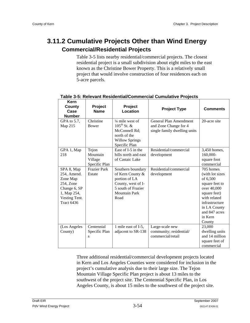
County of Kern Chapter 3. Project Description
Draft EIR September 2007 PdV Wind Energy Project 3-54 002147.EX09.01
3.11.2 Cumulative Projects Other than Wind Energy Commercial/Residential Projects
Table 3-5 lists nearby residential/commercial projects. The closest residential project is a small subdivision about eight miles to the east known as the Christine Bower Property. This is a relatively small project that would involve construction of four residences each on 5-acre parcels.
Table 3-5: Relevant Residential/Commercial Cumulative Projects Kern
County Case
Number
Project Name
Project Location Project Type Comments
GPA to 5.7, Map 215
Christine Bower
¼ mile west of 105th St. & McConnell Rd; north of the Willow Springs Specific Plan
General Plan Amendment and Zone Change for 4 single family dwelling units
20-acre site
GPA 1, Map 218
Tejon Mountain Village Specific Plan
East of I-5 in the hills north and east of Castaic Lake
Residential/commercial development
3,450 homes, 160,000-square foot commercial
SPA 8, Map 254, Amend. Zone Map 254, Zone Change 6, SP 1, Map 254, Vesting Tent. Tract 6436
Frazier Park Estate
Southern boundary of Kern County & portion of LA County, west of I-5 south of Frazier Mountain Park Road
Residential/commercial development
705 homes (with lot sizes of 6,500 square feet to over 40,000 square feet) with related infrastructure in LA County and 847 acres in Kern County
(Los Angeles County)
Centennial Specific Plan s
1 mile east of I-5, adjacent to SR-138
Large-scale new community; residential/ commercial/retail
23,000 dwelling units and 14 million square feet of commercial
Three additional residential/commercial development projects located in Kern and Los Angeles Counties were considered for inclusion in the project’s cumulative analysis due to their large size. The Tejon Mountain Village Specific Plan project is about 13 miles to the southwest of the project site. The Centennial Specific Plan, in Los Angeles County, is about 15 miles to the southwest of the project site.

County of Kern Chapter 3. Project Description
Draft EIR September 2007 PdV Wind Energy Project 3-55 002147.EX09.01
The Frazier Park Estates development is about 23 miles southwest from the project site. The Kern County Planning Department reviewed all known projects within a six-mile radius of the project site. In a database search, 14 separate projects were identified within the applicable township and range; however, none of the identified projects were within six miles of the project site boundary. The closest project to the project site is about eight miles to the east. This project is a subdivision of 20 acres into four 5-acre residential parcels. A zone change request to “E” (Estate District) was submitted in September 2005 to pursue that subdivision project, but there has been no activity since that time. Three additional development projects located in Kern and Los Angeles Counties were considered in the project’s cumulative analysis due to their large size. The Tejon Mountain Village Specific Plan project is located about 13 miles to the southwest of the project site. Centennial Specific Plan is located in Los Angeles County about 15 miles to the southwest of the project site. Both of these projects are located within Tejon Ranch, a privately owned area. The Frazier Park Estates Specific Plan is also considered. These three projects are described further in the paragraphs below. However, because these projects are distant from the project site and are not in the same air basin, they are only included in the Chapter 4 cumulative analysis for relevant environmental topics.
Tejon Mountain Village Specific Plan (GPA 1, Map 218) (Kern County)
The proposed project site consists of 28,253 acres located east of Interstate 5 at the Lake Tejon exit, with a small portion west of Interstate 5. Tejon Ranchcorp (Tejon Ranch Company) proposes to construct Tejon Mountain Village, an approximately 28,253-acre project site; 23,000 acres of the site would be a nature reserve, and approximately 5,000 acres would be developed with a mix of residential, commercial, and recreational uses. The proposed uses include up to 3,450 residences (both single-family and multi-family units) and up to 160,000 square feet of commercial development. This resort development would include various hotel, spa, and resort facilities, with up to 750 lodging units at up to seven locations. There would be a number of recreational and educational facilities, including a nature center, farmers’ market, day camps, equestrian facilities, a sporting clays course, parks, play lawns, swimming and boating facilities, docks on the lake, up to four 18-hole golf courses, and riding
County of Kern Chapter 3. Project Description
Draft EIR September 2007 PdV Wind Energy Project 3-56 002147.EX09.01
and hiking trails. A Specific Plan is currently being prepared for this project.
Frazier Park Estates (Specific Plan Amendment, Case No. 136) (Kern County)
The project proposes a housing and retail development 30 miles south of Bakersfield at the southern boundary of the County in the Frazier Park/Lebec Specific Plan. The proposed master planned community would consist of 705 single-family homes; 41 multi-family units; about 36 acres of commercial and community facilities; and other community support facilities, such as a wastewater treatment plant and a park. Although this development is not located near to the proposed project, some impacts are considered in the cumulative analysis under specific environmental topics.
Centennial Specific Plan (Los Angeles County) The proposed project site consists of 12,000 acres located one mile east of Interstate 5 and adjacent to State Highway 138. The project would include a specific plan and subdivision entitlements (i.e., tract maps and conditional use permits) for a master planned community. The specific plan proposes a maximum of 23,000 dwelling units and 14 million total square feet of non-residential development of employment areas (12,233,390 square feet) and retail serving centers (1,986,336 square feet), anticipated to be built over approximately 20 years. It is estimated that the non-residential development may generate approximately 31,000 jobs.

Figure 3-6
Location of Proposed Fiberoptic Cable Routesand Microwave Telecommunications Tower
PdV Wind Energy ProjectKern County, California
002147.EX09.01.a(Vol2).ai (2007 Corp Archives CD - Vol 2) rev 08/06/2007
Base map: Southern and Central California Atlas and Gazateer (maps 78 and 79), DeLorme Mapping Company, 1990
Proposed Microwave Towerat the Rosamond Substation
PdV CottonwoodPdV Cottonwood
AntelopeSubstation
0 1 2
M I L E S
3 4 5
LancasterLancaster
ROSAMOND BLVD.ROSAMOND BLVD.
AVE. DAVE. D
180T
H S
T.
WE
ST
180T
H S
T.
WE
ST
140T
H S
T.
WE
ST
140T
H S
T.
WE
ST
110T
H S
T.
WE
ST
110T
H S
T.
WE
ST
2
1
3
ProposedCottonwindSubstation
AVE. JAVE. J
Proposed PdV Cottonwood12kV and fiberoptic lines
Proposed fiberoptic cable routes(Segments 1, 2 & 3)1