Chapter 3 Polarization Properties of Prisms and Reflectorsspie.org/samples/PM200.pdf · Chapter 3...
10
Chapter 3 Polarization Properties of Prisms and Reflectors 3.1 Prisms Producing Polarized Light 3.1.1 Uniaxial double-refracting crystals Certain types of crystals, such as calcite (Iceland spar or calcium carbonate) exhibit the property of double refraction or birefringence, as first observed in calcite by Erasmus Bartholinus in 1669. For the class of crystals called uniaxial, there is only one direction where all light rays travel along the same path at a constant velocity. This direction defines the optic axis or principal axis, and any plane that contains the optic axis is called a principal plane (sometimes called a principal section). The optic axis is not a specific line, but indicates a direction in the crystal where there is no double refraction. For all rays not traveling along the optic axis, the velocity is determined by a pair of refractive indices called the ordinary refractive index n o and the extraordinary refractive index n e , and the path of an incident ray is split into two rays, the so-called o-rays and e-rays. Birefringence is specified by the number (n o - n e ). Moreover, these o-rays and e-rays are polarized and vibrate in mutually perpendicular planes. Only rays traveling parallel to the optic axis will not be split, and n o is therefore assigned to this direction. One way to represent this refractive index variation is by use of the indicatrix. 1 Figure 3.1(a) shows a positive uniaxial indicatrix in the shape of an oblate spheroid, where n e > n o , and Fig. 3.1(b) shows a negative uniaxial indicatrix in the shape of a prolate spheroid, where n o > n e . Both have circular symmetry in planes normal to the optic axis, and when the indicatrix has a spherical shape, n e = n o , and the crystal is isotropic. 3.1.2 Nicol polarizing prism One of the first prism polarizers to utilize a birefringent crystal was developed by William Nicol in 1828 and is known as the Nicol prism. The Nicol prism shown in Fig. 3.2 is constructed from negative uniaxial calcite, where n o = 1.6584 and n e = 1.4864 for λ = 589.3 nm. Calcite is a widely used material because of its clarity, stability, high spectral transmission range (200–5000 nm), and high birefringence. Two triangular sections are optically coupled at the hypotenuse by a thin coating of optically clear cement such as Canadian balsam (n cement ≈ 1.54), 61
Transcript of Chapter 3 Polarization Properties of Prisms and Reflectorsspie.org/samples/PM200.pdf · Chapter 3...
Chapter 3Polarization Properties of Prismsand Reflectors
3.1 Prisms Producing Polarized Light
3.1.1 Uniaxial double-refracting crystals
Certain types of crystals, such as calcite (Iceland spar or calcium carbonate) exhibitthe property of double refraction or birefringence, as first observed in calcite byErasmus Bartholinus in 1669. For the class of crystals called uniaxial, there is onlyone direction where all light rays travel along the same path at a constant velocity.This direction defines the optic axis or principal axis, and any plane that containsthe optic axis is called a principal plane (sometimes called a principal section).The optic axis is not a specific line, but indicates a direction in the crystal wherethere is no double refraction. For all rays not traveling along the optic axis, thevelocity is determined by a pair of refractive indices called the ordinary refractiveindex no and the extraordinary refractive index ne, and the path of an incident rayis split into two rays, the so-called o-rays and e-rays. Birefringence is specified bythe number (no − ne). Moreover, these o-rays and e-rays are polarized and vibratein mutually perpendicular planes. Only rays traveling parallel to the optic axis willnot be split, and no is therefore assigned to this direction. One way to representthis refractive index variation is by use of the indicatrix.1 Figure 3.1(a) shows apositive uniaxial indicatrix in the shape of an oblate spheroid, where ne > no, andFig. 3.1(b) shows a negative uniaxial indicatrix in the shape of a prolate spheroid,where no > ne. Both have circular symmetry in planes normal to the optic axis, andwhen the indicatrix has a spherical shape, ne = no, and the crystal is isotropic.
3.1.2 Nicol polarizing prism
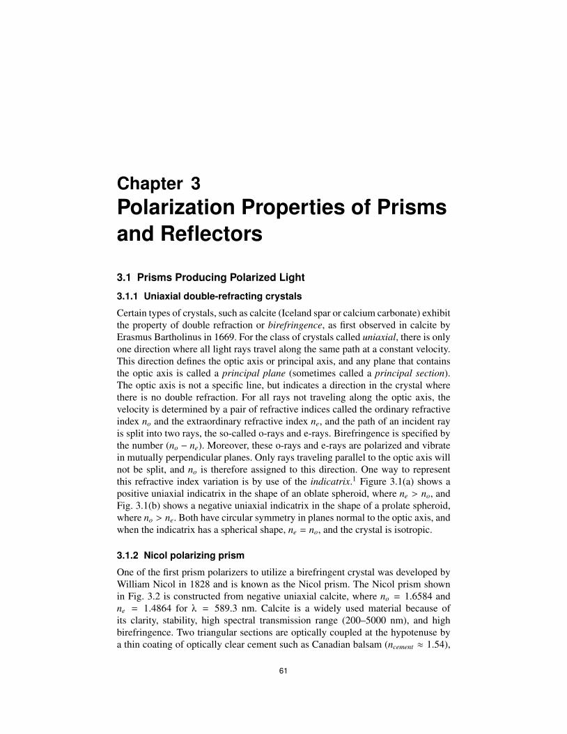
One of the first prism polarizers to utilize a birefringent crystal was developed byWilliam Nicol in 1828 and is known as the Nicol prism. The Nicol prism shownin Fig. 3.2 is constructed from negative uniaxial calcite, where no = 1.6584 andne = 1.4864 for λ = 589.3 nm. Calcite is a widely used material because ofits clarity, stability, high spectral transmission range (200–5000 nm), and highbirefringence. Two triangular sections are optically coupled at the hypotenuse bya thin coating of optically clear cement such as Canadian balsam (ncement ≈ 1.54),
61
62 Chapter 3
Figure 3.1 (a) Positive uniaxial indicatrix (ne > no). (b) Negative uniaxial indicatrix (no > ne).
Figure 3.2 Nicol prism polarizer made of calcite, no = 1.6584, ne = 1.4864.
with the optic axis direction as shown. An incident unpolarized ray is split at theentrance surface, with both rays becoming linearly polarized. By controlling theincident angle of the rays at the interface, the o-ray can undergo total internalreflection (TIR), where Io
crit = arcsin(ncement/no) ≈ 68 deg. Since ncement > ne,the e-ray is always transmitted and exits the prism as linearly polarized light. Thisseparation of o-rays and e-rays by TIR is a useful technique that is used in othertypes of polarizing prisms. Although the exit ray is parallel to the incident ray, thereis a slight lateral displacement (noncollinear), the angular field is limited, and theinterface cement will suffer damage at high power levels.
Polarization Properties of Prisms and Reflectors 63
3.1.3 Glan–Foucault polarizing prism
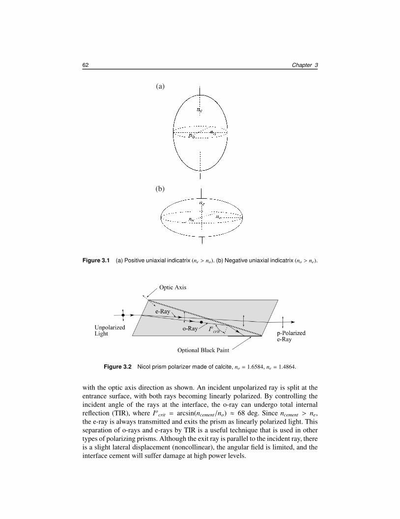
One of several Glan-type polarizing prisms is the Glan–Foucault prism, shown inFig. 3.3(a). The calcite prisms are air spaced at the interface, and each optic axis isperpendicular to the plane of reflection. There is no separation of the ray paths inthe first prism section, but the o-ray moves slower in the first section and undergoesretardance with respect to the e-ray. Again, TIR is used to separate the o-ray fromthe e-ray, and s-polarized light is emitted from the exit face. The o-ray is usuallyabsorbed by blackening the side face. The field of view is determined by TIR failureof the o-ray at the glass–air interface 2, or TIR of the e-ray at this interface. Forcalcite, no = 1.6557 and ne = 1.4852 at λ = 630 nm. The corresponding criticalangles are Io
crit = 37.16 deg and Iecrit = 42.32 deg. As shown in Fig. 3.3(b), the
maximum angle of incidence I1o for the o-ray at entrance surface 1 is estimated
by I1o
max = arcsin[no sin(38.5 deg − Iocrit)] ≈ 2.4 deg. The maximum angle of
incidence I1e for the e-ray is estimated by I1
emax = arcsin[no sin(Io
crit−38.5 deg)] ≈6.3 deg. This results in a narrow asymmetric field of view about the central axisin the tangential plane. A nominal angular field is given as 6 deg at λ = 633 nmby a commercial supplier of the Glan–Foucault prism, United Crystals Company.
Figure 3.3 (a) Glan–Foucault prism polarizer made of calcite, Icrit(no) = 37.1 deg, Icrit(ne) =
42.3 deg. (b) Asymmetric field of view of Glan–Foucault prism polarizer.
64 Chapter 3
Other specifications are a damage threshold of 30 W/cm2 continuous wave (CW)or 300 W/cm2 pulsed laser radiation and transmittance of s-polarized light > 60%at λ = 633 nm.
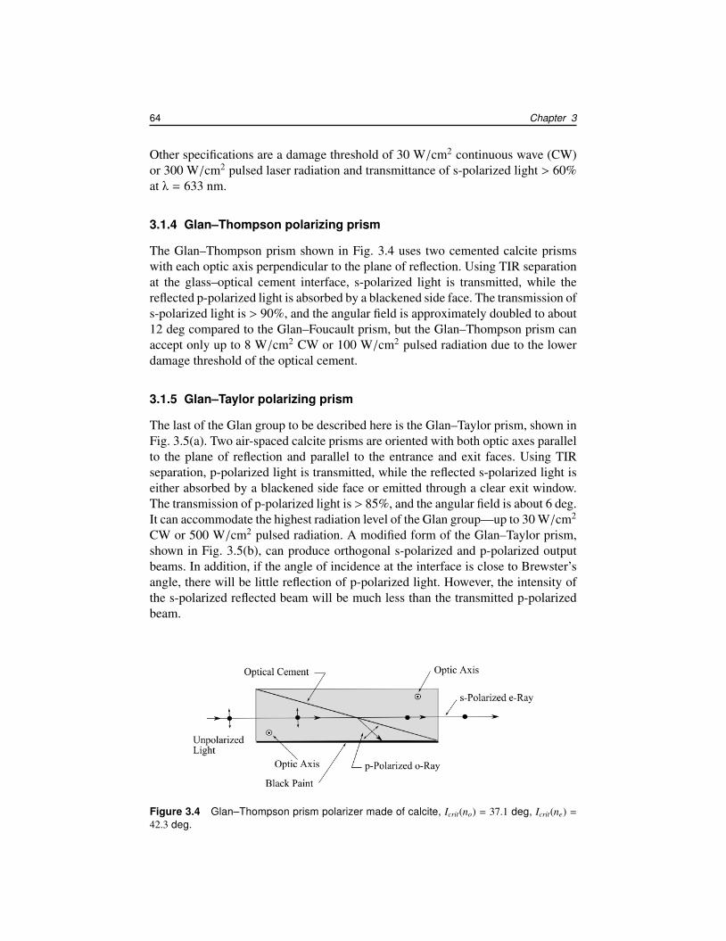
3.1.4 Glan–Thompson polarizing prism
The Glan–Thompson prism shown in Fig. 3.4 uses two cemented calcite prismswith each optic axis perpendicular to the plane of reflection. Using TIR separationat the glass–optical cement interface, s-polarized light is transmitted, while thereflected p-polarized light is absorbed by a blackened side face. The transmission ofs-polarized light is > 90%, and the angular field is approximately doubled to about12 deg compared to the Glan–Foucault prism, but the Glan–Thompson prism canaccept only up to 8 W/cm2 CW or 100 W/cm2 pulsed radiation due to the lowerdamage threshold of the optical cement.
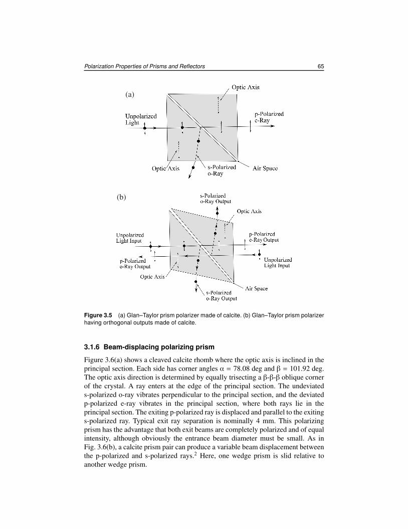
3.1.5 Glan–Taylor polarizing prism
The last of the Glan group to be described here is the Glan–Taylor prism, shown inFig. 3.5(a). Two air-spaced calcite prisms are oriented with both optic axes parallelto the plane of reflection and parallel to the entrance and exit faces. Using TIRseparation, p-polarized light is transmitted, while the reflected s-polarized light iseither absorbed by a blackened side face or emitted through a clear exit window.The transmission of p-polarized light is > 85%, and the angular field is about 6 deg.It can accommodate the highest radiation level of the Glan group—up to 30 W/cm2
CW or 500 W/cm2 pulsed radiation. A modified form of the Glan–Taylor prism,shown in Fig. 3.5(b), can produce orthogonal s-polarized and p-polarized outputbeams. In addition, if the angle of incidence at the interface is close to Brewster’sangle, there will be little reflection of p-polarized light. However, the intensity ofthe s-polarized reflected beam will be much less than the transmitted p-polarizedbeam.
Figure 3.4 Glan–Thompson prism polarizer made of calcite, Icrit(no) = 37.1 deg, Icrit(ne) =
42.3 deg.
Polarization Properties of Prisms and Reflectors 65
Figure 3.5 (a) Glan–Taylor prism polarizer made of calcite. (b) Glan–Taylor prism polarizerhaving orthogonal outputs made of calcite.
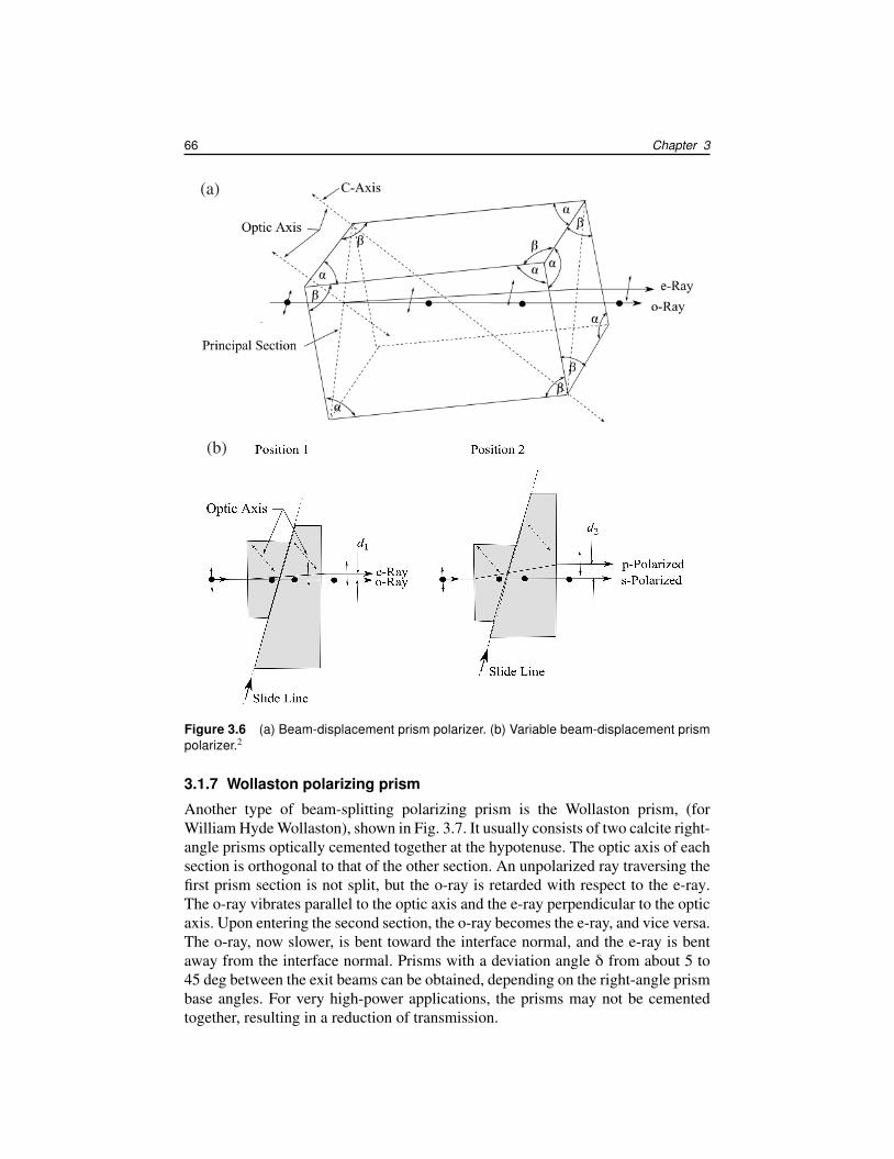
3.1.6 Beam-displacing polarizing prism
Figure 3.6(a) shows a cleaved calcite rhomb where the optic axis is inclined in theprincipal section. Each side has corner angles α = 78.08 deg and β = 101.92 deg.The optic axis direction is determined by equally trisecting a β-β-β oblique cornerof the crystal. A ray enters at the edge of the principal section. The undeviateds-polarized o-ray vibrates perpendicular to the principal section, and the deviatedp-polarized e-ray vibrates in the principal section, where both rays lie in theprincipal section. The exiting p-polarized ray is displaced and parallel to the exitings-polarized ray. Typical exit ray separation is nominally 4 mm. This polarizingprism has the advantage that both exit beams are completely polarized and of equalintensity, although obviously the entrance beam diameter must be small. As inFig. 3.6(b), a calcite prism pair can produce a variable beam displacement betweenthe p-polarized and s-polarized rays.2 Here, one wedge prism is slid relative toanother wedge prism.
66 Chapter 3
Figure 3.6 (a) Beam-displacement prism polarizer. (b) Variable beam-displacement prismpolarizer.2
3.1.7 Wollaston polarizing prism
Another type of beam-splitting polarizing prism is the Wollaston prism, (forWilliam Hyde Wollaston), shown in Fig. 3.7. It usually consists of two calcite right-angle prisms optically cemented together at the hypotenuse. The optic axis of eachsection is orthogonal to that of the other section. An unpolarized ray traversing thefirst prism section is not split, but the o-ray is retarded with respect to the e-ray.The o-ray vibrates parallel to the optic axis and the e-ray perpendicular to the opticaxis. Upon entering the second section, the o-ray becomes the e-ray, and vice versa.The o-ray, now slower, is bent toward the interface normal, and the e-ray is bentaway from the interface normal. Prisms with a deviation angle δ from about 5 to45 deg between the exit beams can be obtained, depending on the right-angle prismbase angles. For very high-power applications, the prisms may not be cementedtogether, resulting in a reduction of transmission.
Polarization Properties of Prisms and Reflectors 67
Figure 3.7 Wollaston prism polarizer (calcite).
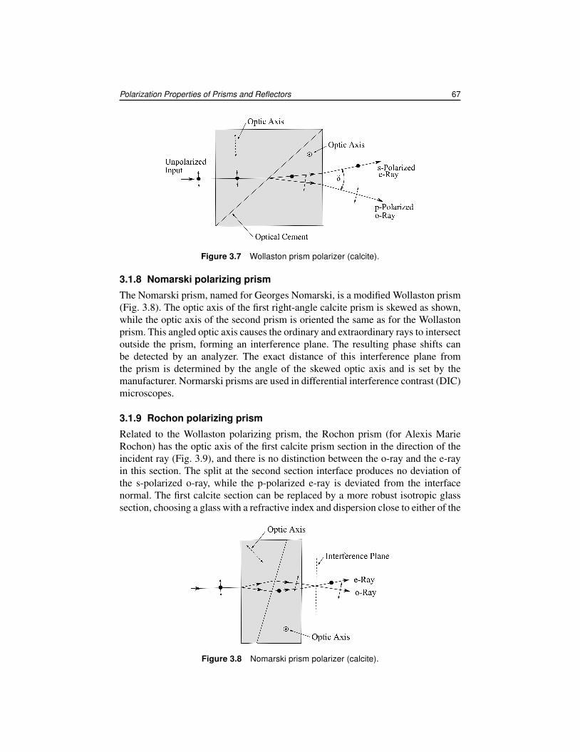
3.1.8 Nomarski polarizing prism
The Nomarski prism, named for Georges Nomarski, is a modified Wollaston prism(Fig. 3.8). The optic axis of the first right-angle calcite prism is skewed as shown,while the optic axis of the second prism is oriented the same as for the Wollastonprism. This angled optic axis causes the ordinary and extraordinary rays to intersectoutside the prism, forming an interference plane. The resulting phase shifts canbe detected by an analyzer. The exact distance of this interference plane fromthe prism is determined by the angle of the skewed optic axis and is set by themanufacturer. Normarski prisms are used in differential interference contrast (DIC)microscopes.
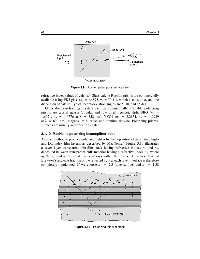
3.1.9 Rochon polarizing prism
Related to the Wollaston polarizing prism, the Rochon prism (for Alexis MarieRochon) has the optic axis of the first calcite prism section in the direction of theincident ray (Fig. 3.9), and there is no distinction between the o-ray and the e-rayin this section. The split at the second section interface produces no deviation ofthe s-polarized o-ray, while the p-polarized e-ray is deviated from the interfacenormal. The first calcite section can be replaced by a more robust isotropic glasssection, choosing a glass with a refractive index and dispersion close to either of the
Figure 3.8 Nomarski prism polarizer (calcite).
68 Chapter 3
Figure 3.9 Rochon prism polarizer (calcite).
refractive index values of calcite.3 Glass-calcite Rochon prisms are commerciallyavailable using FK5 glass (nd = 1.4875, νd = 70.41), which is close to ne and thedispersion of calcite. Typical beam-deviation angles are 5, 10, and 15 deg.
Other double-refracting crystals used in commercially available polarizingprisms are crystal quartz (circular and low birefringence), alpha-BBO (ne =
1.6021, no = 1.6776 at λ = 552 nm), YVO4 (ne = 2.2154, no = 1.9929at λ = 630 nm), magnesium fluoride, and titanium dioxide. Polarizing prisms’surfaces are usually antireflection coated.
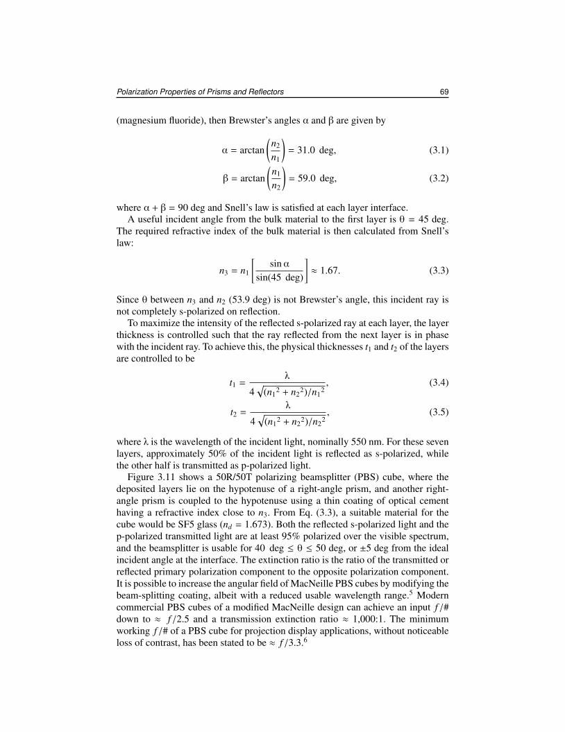
3.1.10 MacNeille polarizing beamsplitter cube
Another method to produce polarized light is by the deposition of alternating high-and low-index film layers, as described by MacNeille.4 Figure 3.10 illustratesa seven-layer transparent thin-film stack having refractive indices n1 and n2,deposited between transparent bulk material having a refractive index n3, wheren1 � n2, and n1 > n3. All internal rays within the layers hit the next layer atBrewster’s angle. A fraction of the reflected light at each layer interface is thereforecompletely s-polarized. If we choose n1 = 2.3 (zinc sulfide) and n2 = 1.38
Figure 3.10 Polarizing thin-film stack.
Polarization Properties of Prisms and Reflectors 69
(magnesium fluoride), then Brewster’s angles α and β are given by
α = arctan(n2
n1
)= 31.0 deg, (3.1)
β = arctan(n1
n2
)= 59.0 deg, (3.2)
where α + β = 90 deg and Snell’s law is satisfied at each layer interface.A useful incident angle from the bulk material to the first layer is θ = 45 deg.
The required refractive index of the bulk material is then calculated from Snell’slaw:
n3 = n1
[sinα
sin(45 deg)
]≈ 1.67. (3.3)
Since θ between n3 and n2 (53.9 deg) is not Brewster’s angle, this incident ray isnot completely s-polarized on reflection.
To maximize the intensity of the reflected s-polarized ray at each layer, the layerthickness is controlled such that the ray reflected from the next layer is in phasewith the incident ray. To achieve this, the physical thicknesses t1 and t2 of the layersare controlled to be
t1 =λ
4√
(n12 + n2
2)/n12, (3.4)
t2 =λ
4√
(n12 + n2
2)/n22, (3.5)
where λ is the wavelength of the incident light, nominally 550 nm. For these sevenlayers, approximately 50% of the incident light is reflected as s-polarized, whilethe other half is transmitted as p-polarized light.
Figure 3.11 shows a 50R/50T polarizing beamsplitter (PBS) cube, where thedeposited layers lie on the hypotenuse of a right-angle prism, and another right-angle prism is coupled to the hypotenuse using a thin coating of optical cementhaving a refractive index close to n3. From Eq. (3.3), a suitable material for thecube would be SF5 glass (nd = 1.673). Both the reflected s-polarized light and thep-polarized transmitted light are at least 95% polarized over the visible spectrum,and the beamsplitter is usable for 40 deg ≤ θ ≤ 50 deg, or ±5 deg from the idealincident angle at the interface. The extinction ratio is the ratio of the transmitted orreflected primary polarization component to the opposite polarization component.It is possible to increase the angular field of MacNeille PBS cubes by modifying thebeam-splitting coating, albeit with a reduced usable wavelength range.5 Moderncommercial PBS cubes of a modified MacNeille design can achieve an input f /#down to ≈ f /2.5 and a transmission extinction ratio ≈ 1,000:1. The minimumworking f /# of a PBS cube for projection display applications, without noticeableloss of contrast, has been stated to be ≈ f /3.3.6
70 Chapter 3
Figure 3.11 MacNeille 50R/50T PBS cube in convergent beam of half-angle θ.
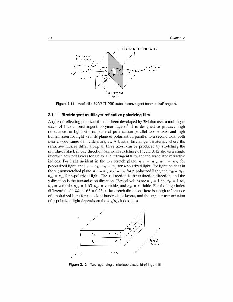
3.1.11 Birefringent multilayer reflective polarizing film
A type of reflecting polarizer film has been developed by 3M that uses a multilayerstack of biaxial birefringent polymer layers.7 It is designed to produce highreflectance for light with its plane of polarization parallel to one axis, and hightransmission for light with its plane of polarization parallel to a second axis, bothover a wide range of incident angles. A biaxial birefringent material, where therefractive indices differ along all three axes, can be produced by stretching themultilayer stack in one direction (uniaxial stretching). Figure 3.12 shows a singleinterface between layers for a biaxial birefringent film, and the associated refractiveindices. For light incident in the x-y stretch plane, n10 = n1x, n20 = n2x forp-polarized light, and n10 = n1y, n20 = n2y for s-polarized light. For light incident inthe y-z nonstretched plane, n10 = n1y, n20 = n2y for p-polarized light, and n10 = n1x,n20 = n2x for s-polarized light. The x direction is the extinction direction, and they direction is the transmission direction. Typical values are n1x = 1.88, n1y = 1.64,n1z = variable, n2x = 1.65, n2y = variable, and n2z = variable. For the large indexdifferential of 1.88−1.65 = 0.23 in the stretch direction, there is a high reflectanceof s-polarized light for a stack of hundreds of layers, and the angular transmissionof p-polarized light depends on the n1z/n2z index ratio.
Figure 3.12 Two-layer single interface biaxial birefringent film.