Chapter 3 Orthographic Projection - WordPress.com fileTOPICS Object representation Glass box concept...
39
Chapter 3 Orthographic Projection
Transcript of Chapter 3 Orthographic Projection - WordPress.com fileTOPICS Object representation Glass box concept...
Chapter 3
Orthographic
Projection
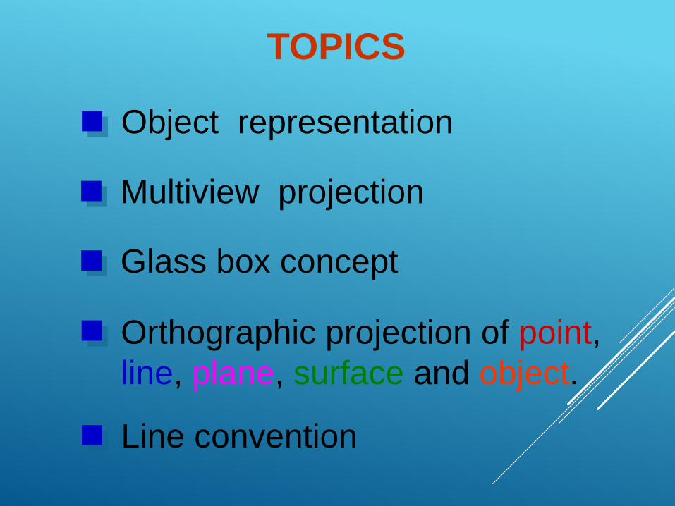
TOPICS
Object representation
Glass box concept
Line convention
Orthographic projection of point,
line, plane, surface and object.
Multiview projection
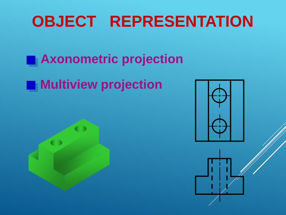
OBJECT REPRESENTATION
Axonometric projection
Multiview projection
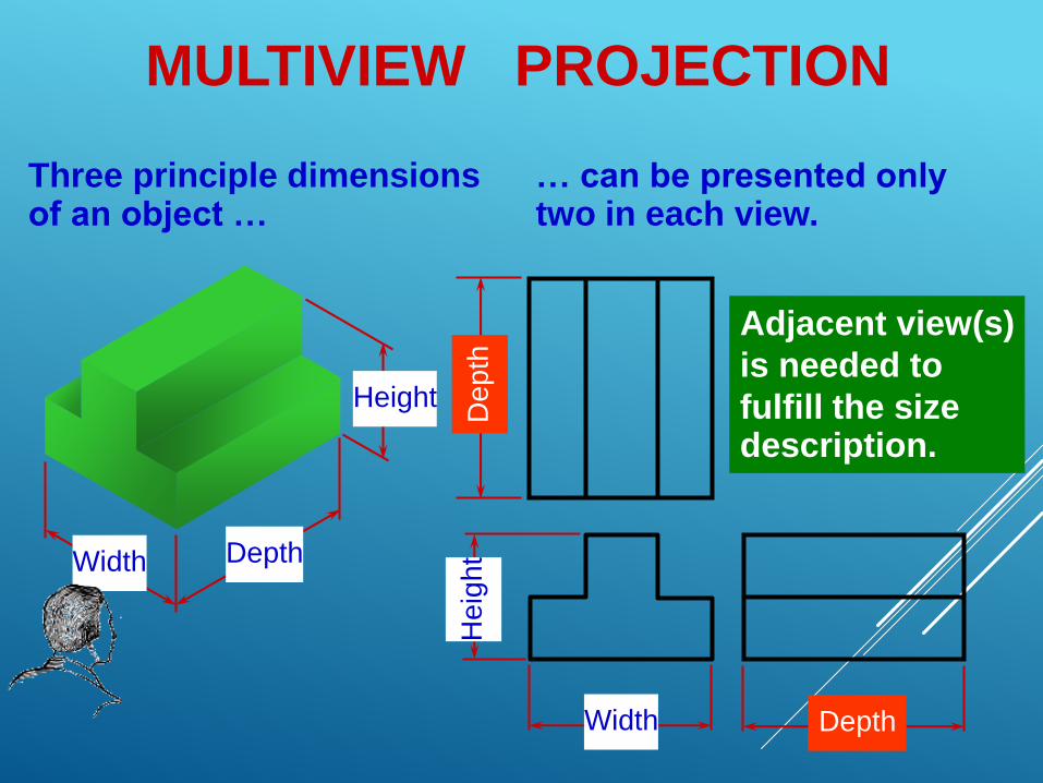
MULTIVIEW PROJECTION
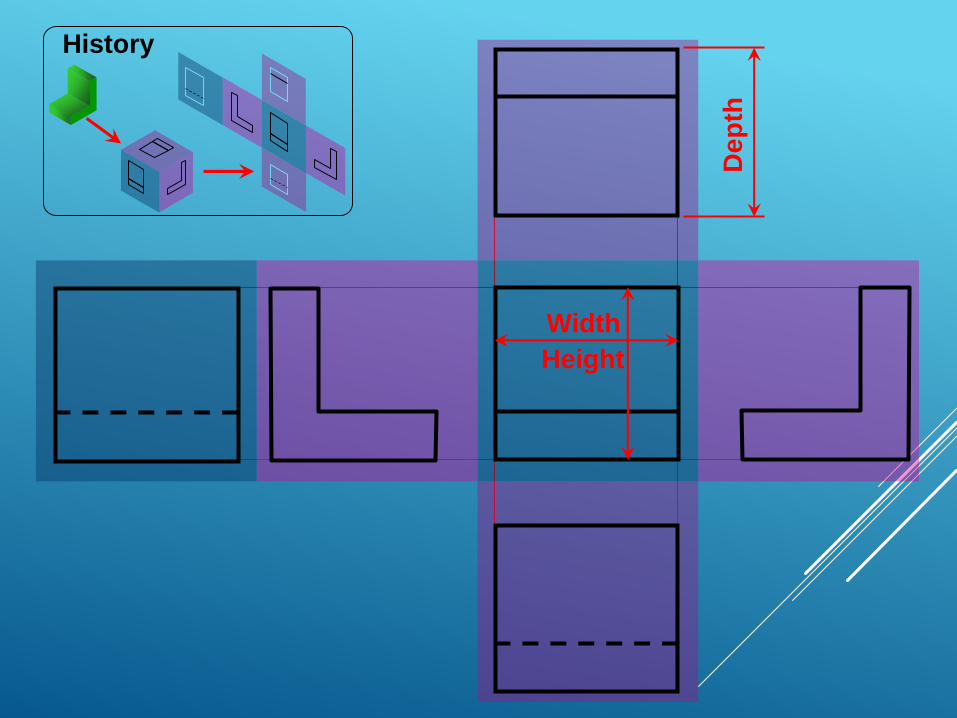
Three principle dimensionsof an object …
Width Depth
Height
Width
He
igh
t
Depth
De
pth
… can be presented onlytwo in each view.
Adjacent view(s)
is needed to
fulfill the sizedescription.
1. Revolve the object with respect
to observer.
TO OBTAIN MULTIVIEW
REPRESENTATION OF AN OBJECT
2. The observer move around the
object.
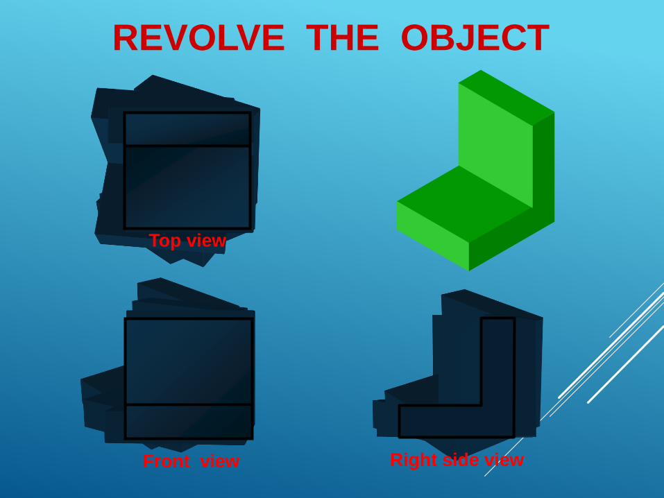
REVOLVE THE OBJECT
Front view Right side view
Top view
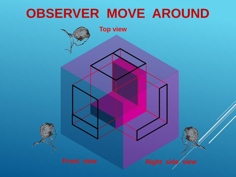
OBSERVER MOVE AROUND
Front view Right side view
Top view
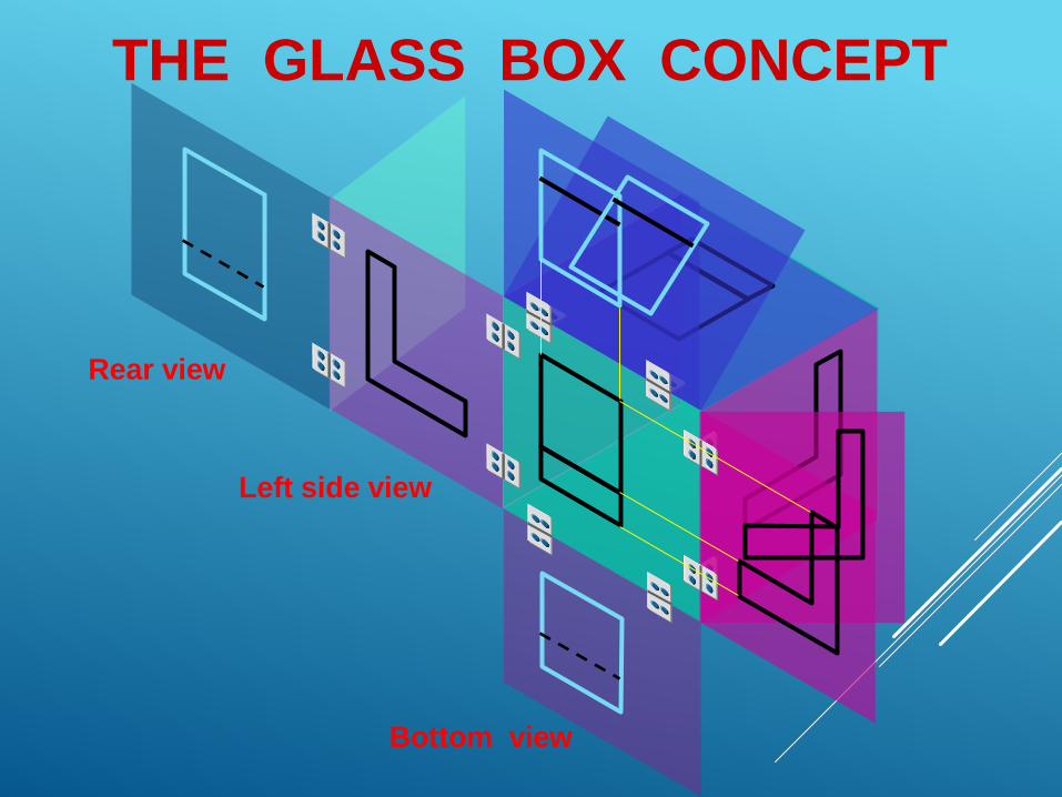
THE GLASS BOX CONCEPT
Bottom view
Left side view
Rear view
Height
Width
De
pth
History
Orthographic
Projection
of Object Features
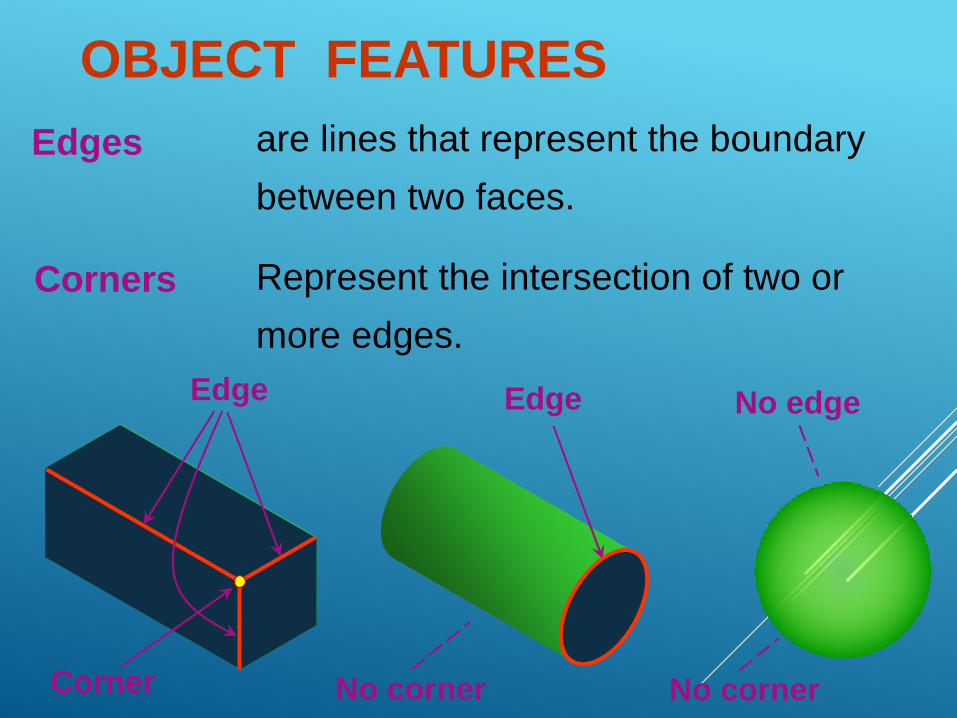
OBJECT FEATURES
Edges are lines that represent the boundary
between two faces.
Corners Represent the intersection of two or
more edges.
Edge
Corner
Edge No edge
No corner No corner
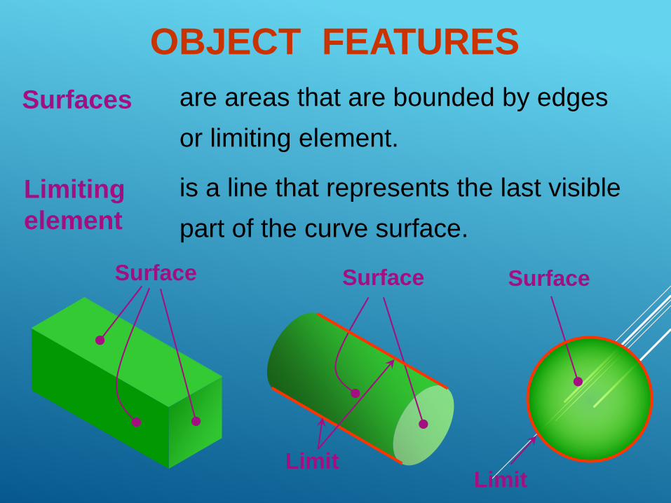
Surfaces are areas that are bounded by edges
or limiting element.
Limiting
element
is a line that represents the last visible
part of the curve surface.
Surface Surface Surface
LimitLimit
OBJECT FEATURES
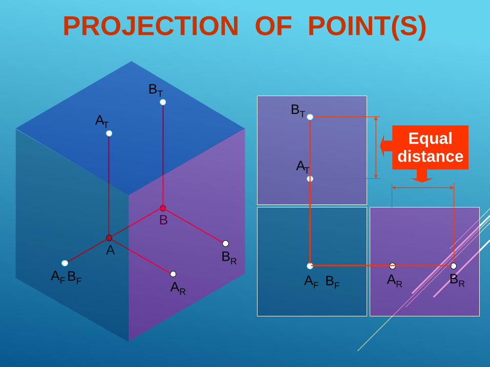
A
B
PROJECTION OF POINT(S)
AF
BR
AT
BFAR
BT
AFAR
AT
BFBR
BT
Equaldistance
A
B
AF BF BRAR
AT
BT
BR
AR
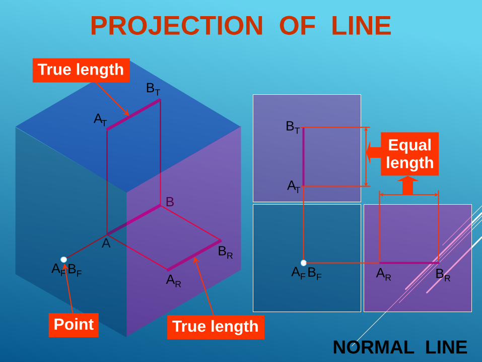
AF BF
AT
BT
True length
NORMAL LINETrue lengthPoint
Equallength
PROJECTION OF LINE
AB
AF BF BRAR
AT
BT
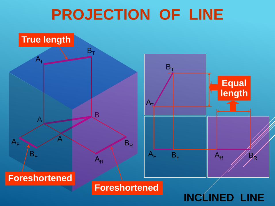
INCLINED LINEForeshortened
BR
AR
AF
BF
Foreshortened
AT
BT
True length
A
Equallength
PROJECTION OF LINE
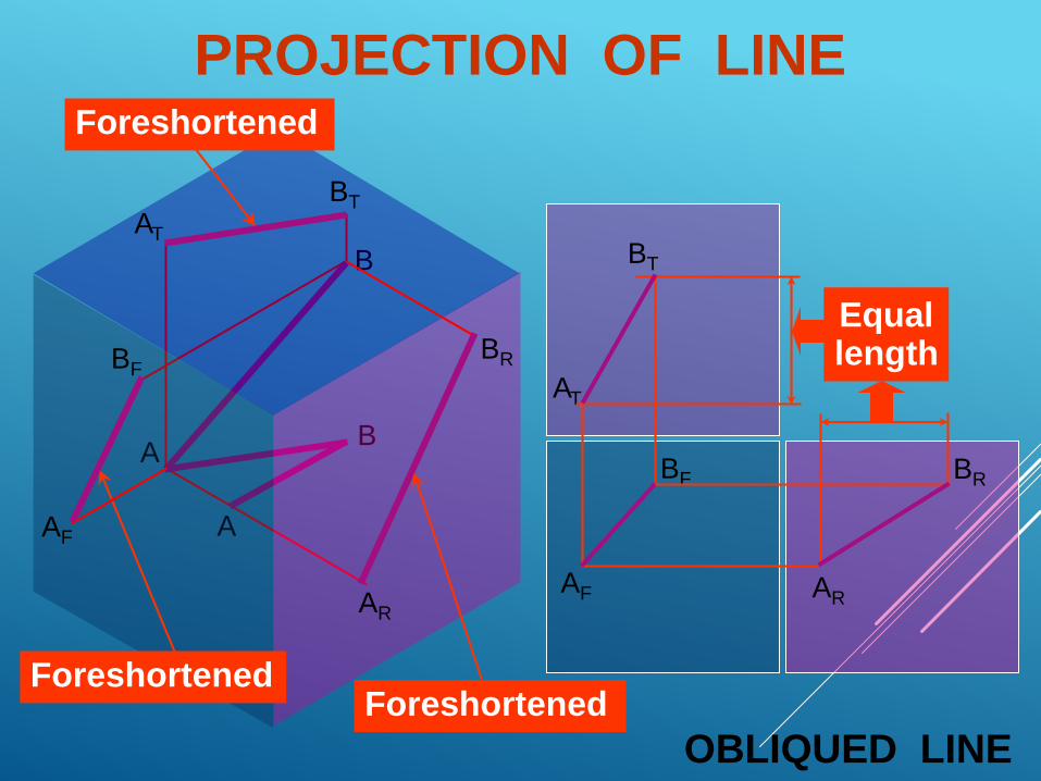
AB
AF
BF BR
AR
AT
BT
OBLIQUED LINE
A
Equallength
B
ForeshortenedForeshortened
Foreshortened
BR
AR
AF
BF
AT
BT
PROJECTION OF LINE
BC
A
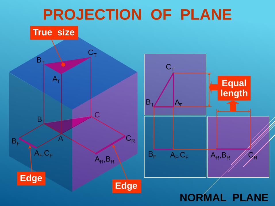
PROJECTION OF PLANE
BF AF,CF CRAR,BR
AT
CT
NORMAL PLANE
Equallength
EdgeEdge
True size
CR
AR,BR
AF,CF
BF
AT
BT
CT
BT
BC
BF AF
CR
AR,BR
AT
CT
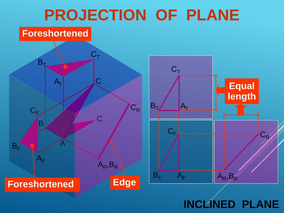
INCLINED PLANE
A
Equallength
BT
C
CF
Edge
CR
AR,BR
Foreshortened
BT
CT
AT
AF
CF
Foreshortened
BF
PROJECTION OF PLANE
BC
BF
AF
CR
AR
AT
CT
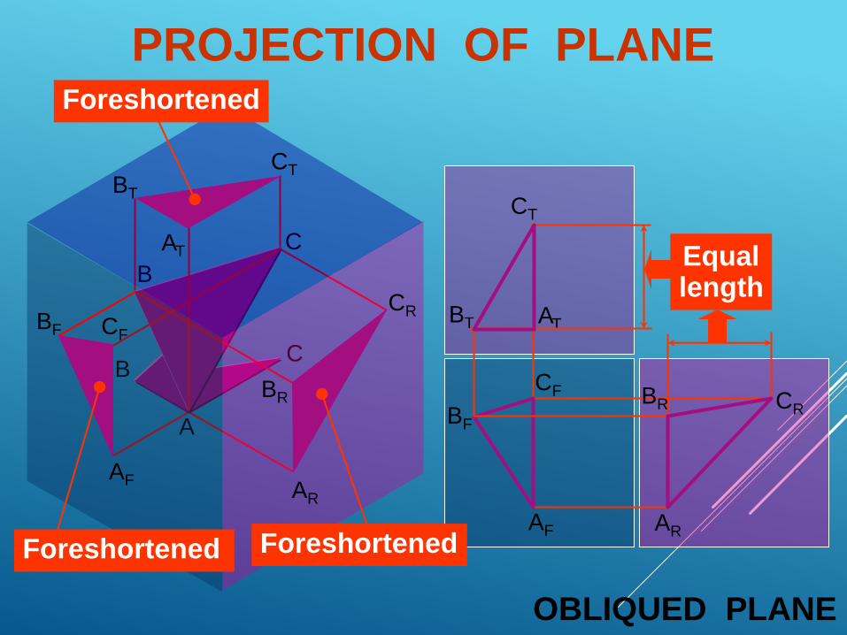
OBLIQUED PLANE
A
Equallength
BT
C
CF
B
BR
Foreshortened
CR
AR
BR
AF
BF CF
Foreshortened
AT
BT
CT
Foreshortened
PROJECTION OF PLANE
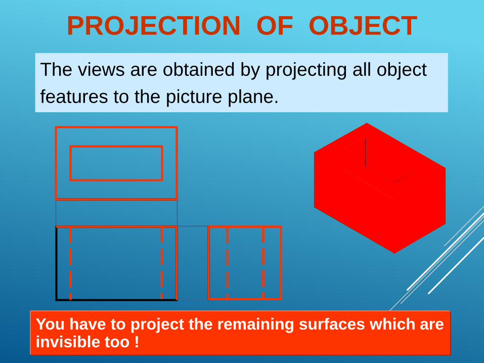
PROJECTION OF OBJECT
The views are obtained by projecting all object
features to the picture plane.
You have to project the remaining surfaces which areinvisible too !
s
s
s
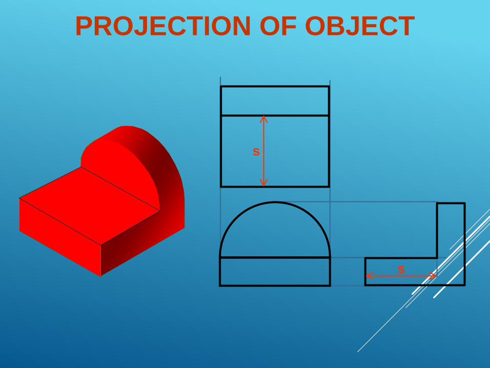
PROJECTION OF OBJECT
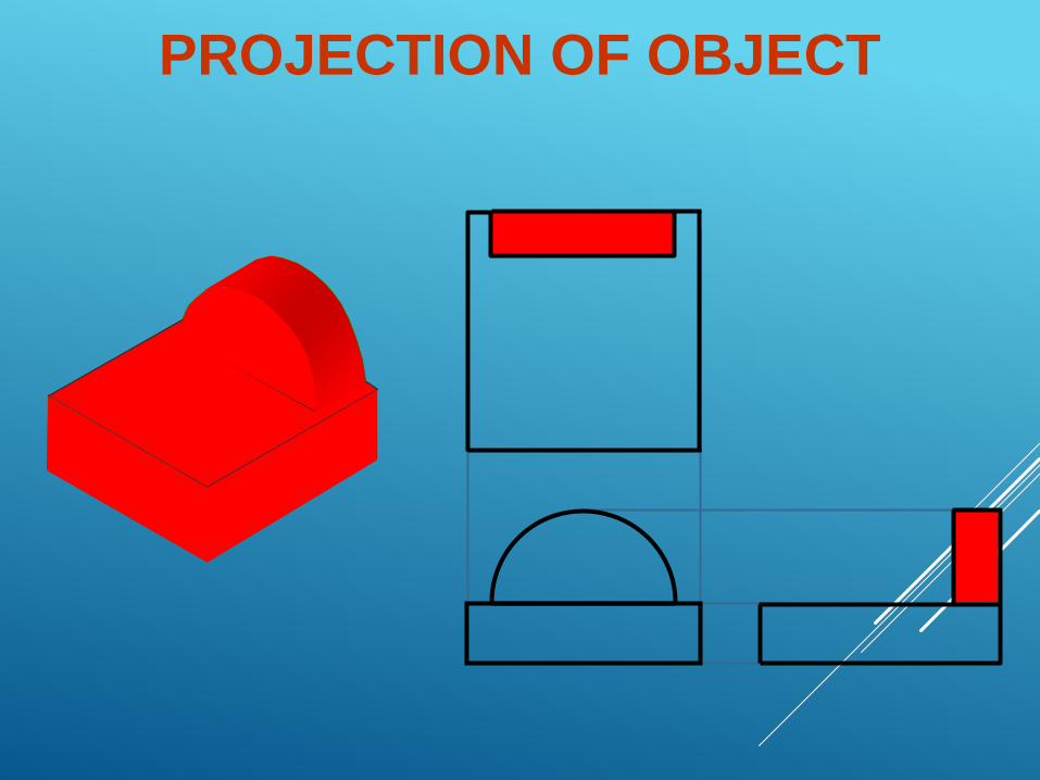
PROJECTION OF OBJECT
Line Convention
LINE CONVENTION
Precedence of coincide lines.
Hidden line drawing.
Center line drawing.
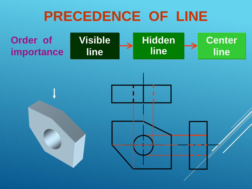
PRECEDENCE OF LINE
Visible
line
Order of
importance
Hiddenline
Center
line
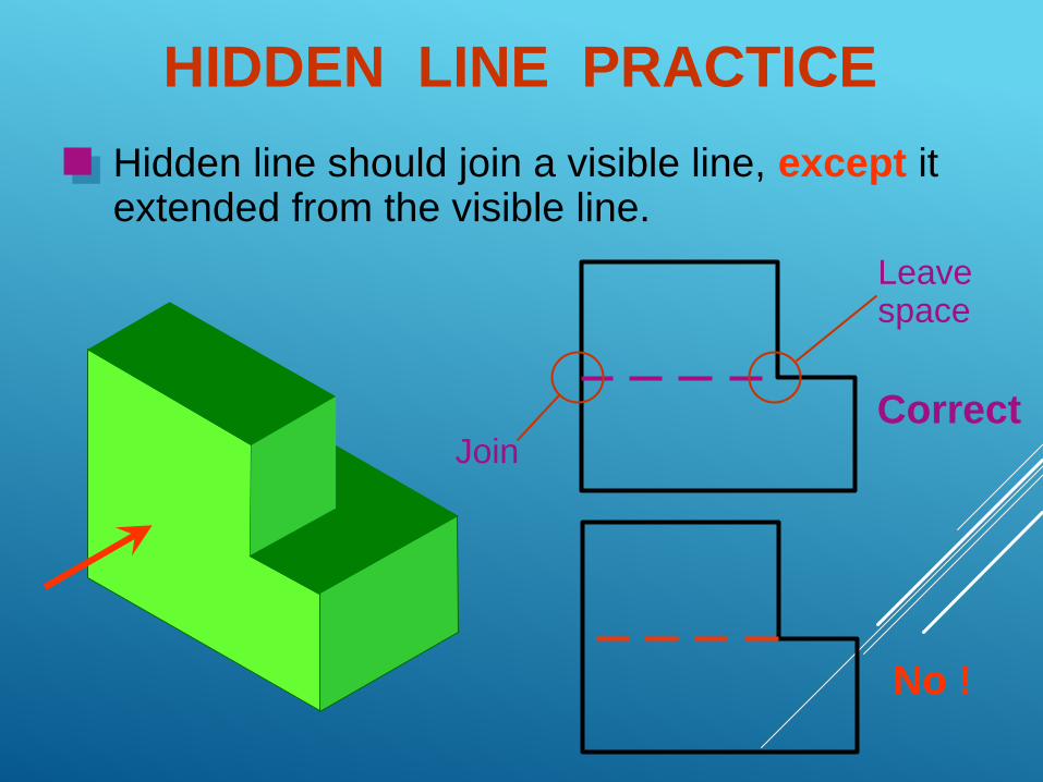
HIDDEN LINE PRACTICE
Hidden line should join a visible line, except itextended from the visible line.
Correct
No !
Join
Leavespace
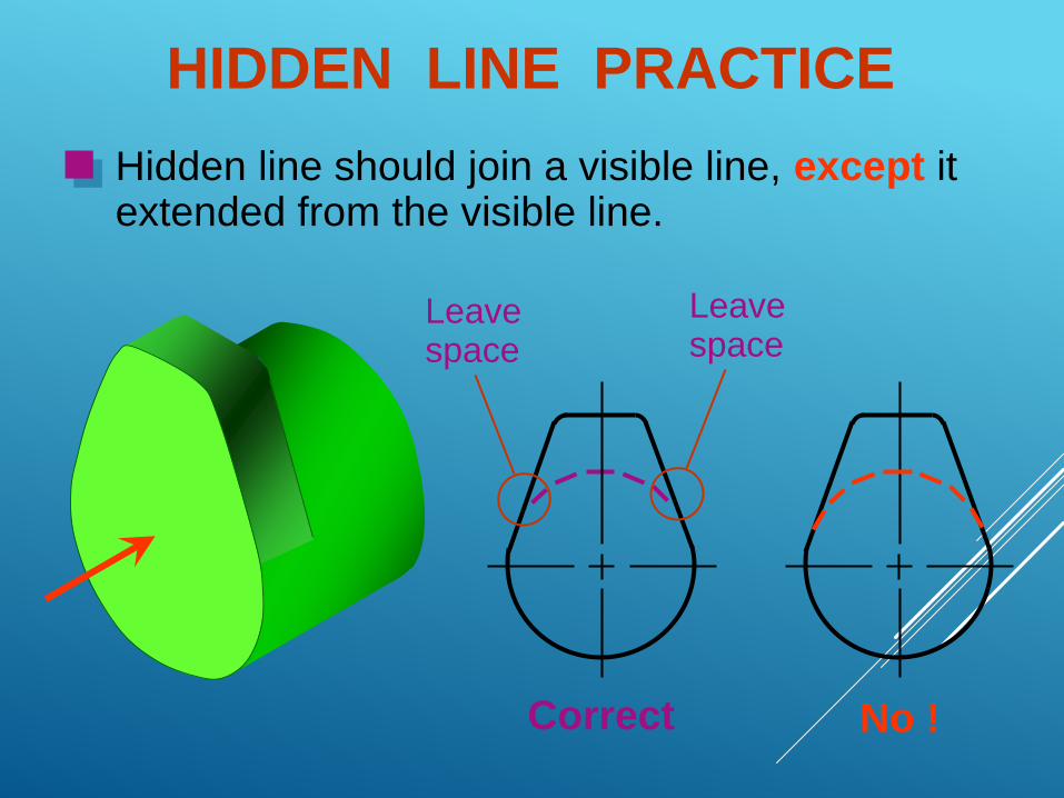
Correct No !
Hidden line should join a visible line, except itextended from the visible line.
Leavespace
Leavespace
HIDDEN LINE PRACTICE
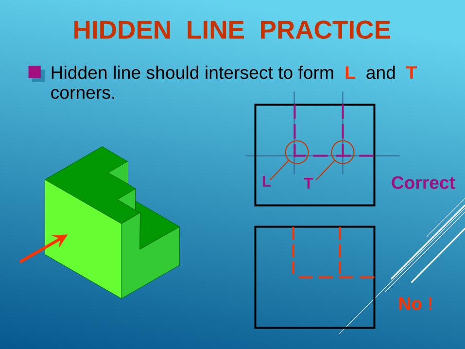
Hidden line should intersect to form L and Tcorners.
Correct
No !
L T
HIDDEN LINE PRACTICE
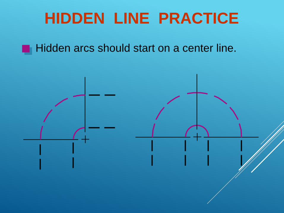
Hidden arcs should start on a center line.
HIDDEN LINE PRACTICE
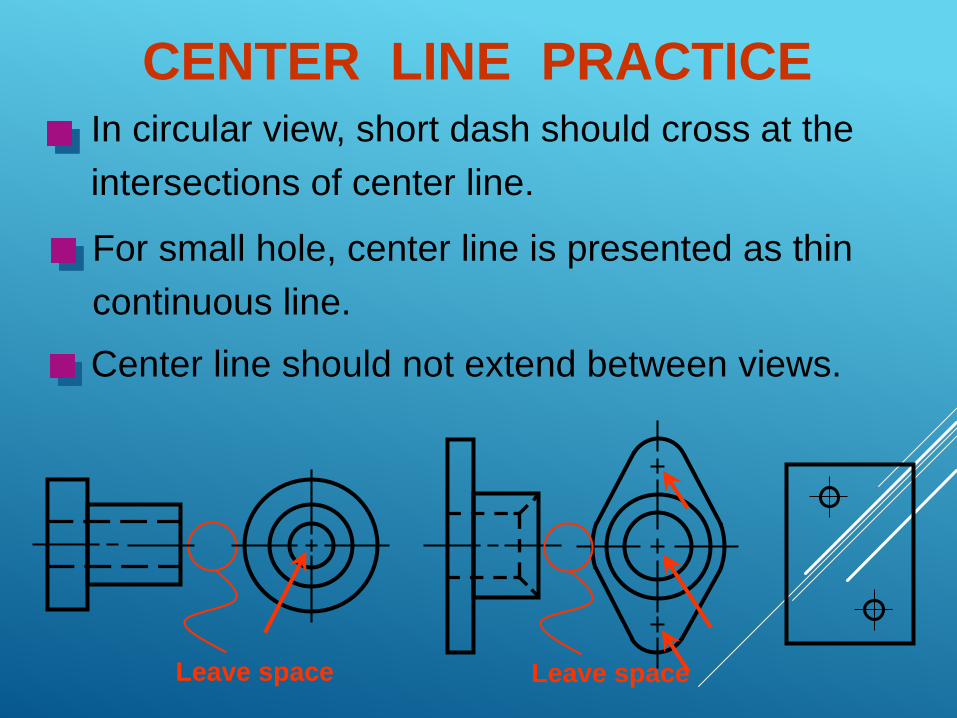
CENTER LINE PRACTICEIn circular view, short dash should cross at the
intersections of center line.
For small hole, center line is presented as thin
continuous line.
Center line should not extend between views.
Leave space Leave space
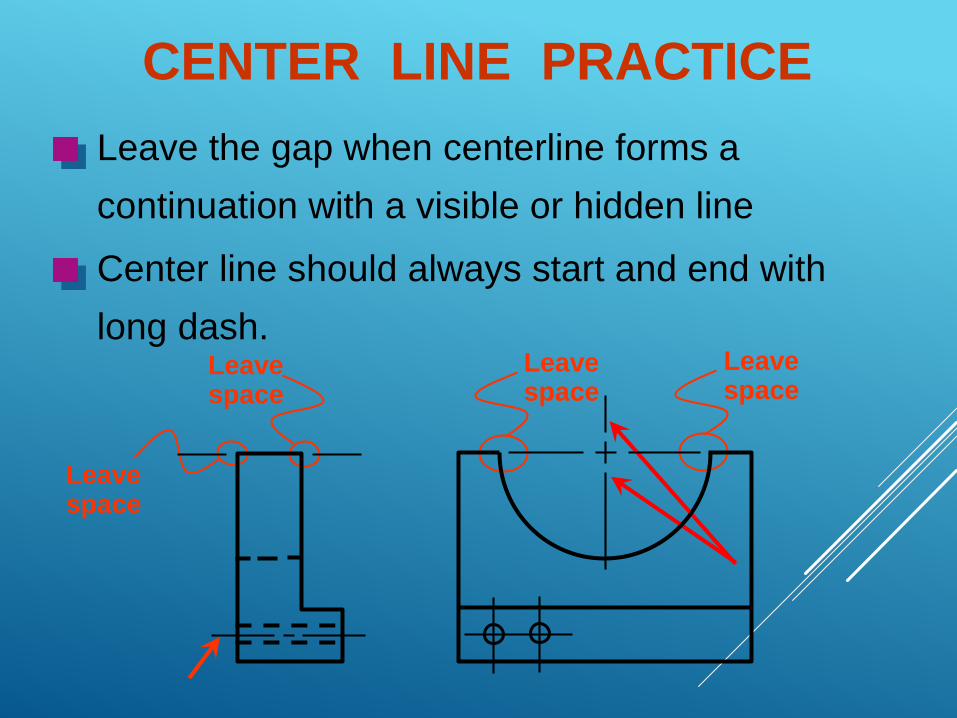
Leave the gap when centerline forms a
continuation with a visible or hidden line
Leavespace
Leavespace
Leavespace
Leavespace
Center line should always start and end with
long dash.
CENTER LINE PRACTICE
Chapter 4
Orthographic
Writing
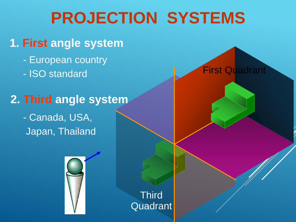
PROJECTION SYSTEMS
1. First angle system
2. Third angle system
First Quadrant
ThirdQuadrant
- European country
- ISO standard
- Canada, USA,
Japan, Thailand
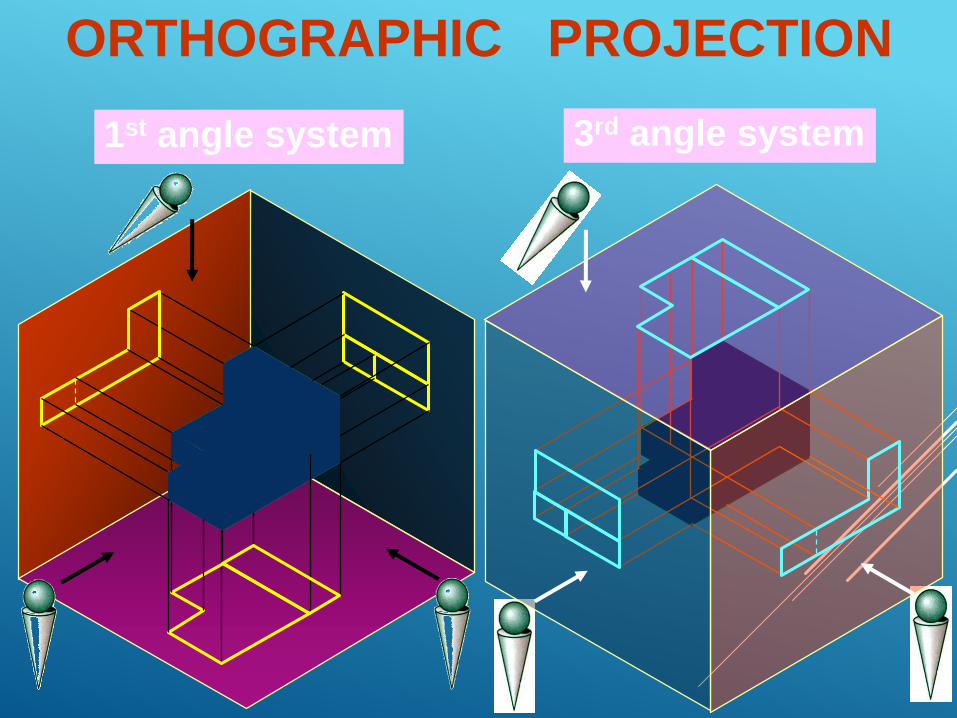
ORTHOGRAPHIC PROJECTION
1st angle system 3rd angle system
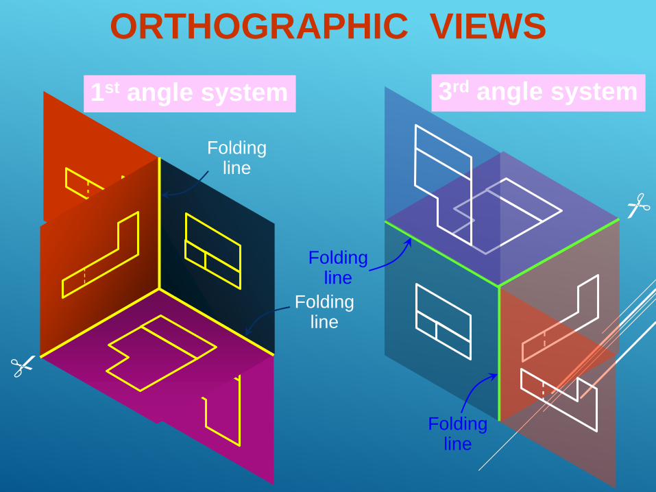
ORTHOGRAPHIC VIEWS
1st angle system 3rd angle system
Foldingline
Foldingline
Foldingline
Foldingline
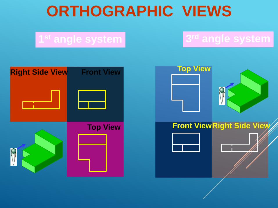
ORTHOGRAPHIC VIEWS
1st angle system 3rd angle system
Front View
Front View
Right Side View
Right Side View
Top View
Top View
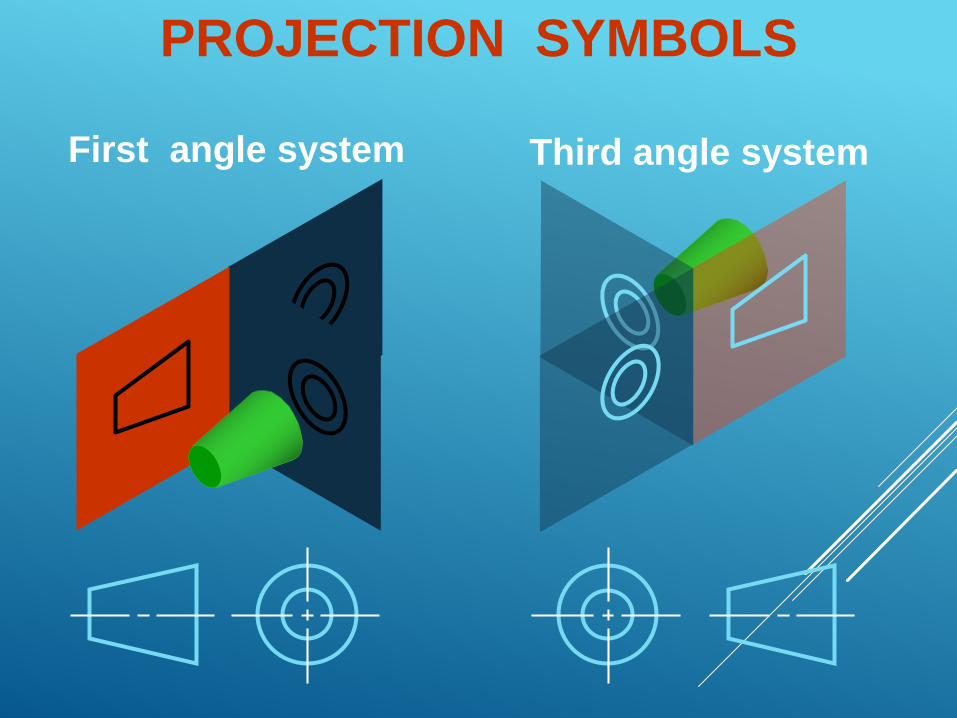
First angle system Third angle system
PROJECTION SYMBOLS
BASIC DIMENSIONING
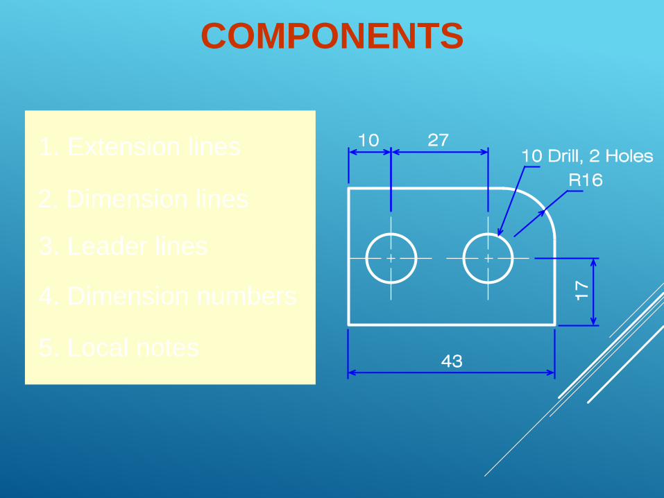
1. Extension lines
2. Dimension lines
3. Leader lines
4. Dimension numbers
5. Local notes
COMPONENTS
10 27
43
10 Drill, 2 Holes
R16
17