CHAPTER 3 INFORMATION ON APPLICATION FOR SUPPLY · 3.6 6. If there is no central metering cubicle...
107
CHAPTER 3 INFORMATION ON APPLICATION FOR SUPPLY
Transcript of CHAPTER 3 INFORMATION ON APPLICATION FOR SUPPLY · 3.6 6. If there is no central metering cubicle...

CHAPTER 3
INFORMATION ON
APPLICATION FOR SUPPLY
3.1
CHAPTER 3 INFORMATION ON APPLICATION FOR SUPPLY 3.1 Application for Supply to New Building 1. Supply would, as decided by HK Electric, either be provided by
establishing a customer substation at the building or by direct cables from existing low voltage network.
2. Supply arrangement, requirements of substation/cable entry ducts and
other facilities required for provision of supply would normally be agreed with the authorised architect/consultant responsible for the development at an early stage of the building construction.
3. For supply with establishment of a new substation, the substation should
be constructed and handed over to HK Electric in a complete condition and other facilities (as required) provided. Installation work will take about six weeks to complete after acceptance of all these facilities provided by the developers, payment of service charge (if any) and after receipt of all necessary permits issued by relevant government authority/private land owner. [Please see Clause 3.10 (1 & 2)]
4. For supply from existing low voltage network, the cable entry ducts and
other facilities as required should be provided. Installation work will take about four weeks to complete after acceptance of all these facilities, payment of service charge (if any) and after receipt of all necessary permits issued by relevant government authority/private land owner. [Please see Clause 3.10 (1 & 2)]
5. Under normal circumstances, the supply scheme will be prepared and
service charge (if any) determined in about two weeks after receipt of formal application for supply. For exceptional cases where special type of equipment or complicated supply arrangements are involved, an additional two weeks may be needed for determination of service charge. [Please see Clause 3.10 (1 & 2)]
3.2
3.2 Application for Supply to Village Houses on Hong Kong Island or 3-Storey Houses on Lamma Island
1. Supply would normally be provided by direct cables from existing low
voltage network. However, there would be some special cases where supply would be provided by low voltage overhead wires.
2. Formal application for supply should be submitted as early as possible.
The applicant will be advised of HK Electric's requirements of the cable entry ducts, weatherproof enclosure and/or other facilities in about four weeks upon receipt of the application.
3. Apart from preparation of the supply scheme, approval of excavation
permit from District Lands Office will require about another three months. Should there be any private lot involved along the excavation route, written approval from all private lot owners must be received before the applicant is asked to pay the service charge required for provision of supply.
4. The cable entry ducts, weatherproof enclosure and/or other facilities as
required should be provided. Installation work will take about four weeks to complete after acceptance of all these facilities, payment of service charge (if any) and receipt of all necessary permits issued by relevant government authority/private land owner. [Please see Clause 3.10 (1 & 2)]
3.3 Application for Supply (New or Additional) at Existing Building 1. It must not be assumed that such supply (even if it is a small supply or
application for transfer) at existing building can be obtained at short notice because the existing supply system may have already been loaded to its capacity and need reinforcement.
2. For application of a very large supply, a new substation or extension of the
existing substation at the building may be required. This will involve alteration of building plans and will have to be handled by authorised architect/consultant. The whole process of providing supply including negotiation of substation space, approval from relevant Government Authorities, construction/extension of substation, inspection and handing over of substation, commissioning of substation and connection of supply may take six months to a few years.
3.3
3. Application of smaller supply may also necessitate the installation of
additional service cable or replacement of existing service cable supplying the building. The applicant will be advised of the supply situation, HK Electric's requirements of the cable entry ducts and other facilities, and service charge required for provision of supply (if any) in about three weeks upon receipt of the application. The cable installation work will take about four weeks to complete after acceptance of all these facilities, payment of service charge (if any) and after receipt of all necessary permits issued by relevant government authority/private land owner. [Please see Clause 3.10 (1 & 2)]
4. The processing time will be much shorter if the application for supply does not require any reinforcement work by HK Electric.
5. It is always the customer's REC/REW responsibility to ensure that prior
consent has been obtained from the building management and/or the owners incorporation of the building regarding connection of customer's new or additional load to the distribution system of the building and that connection of customer's new or additional installation will not cause overload to the distribution system of the building.
6. To help speed up the processing of application for supply, the applicants or
their RECs/REWs are requested to complete Form DP1 to provide the information on Supply Number details from which the proposed electrical installation will be supplied.
7. The work flow and telephone contact list for application for additional
load is shown in Drg. No. GCS/3/01.
3.4 Application for Temporary Supply to Construction Sites 1. Supply would normally be provided either by establishing a transformer
pillar at the site or by direct cables from existing low voltage network up to the boundary of the site.
3.4
2. If the requested load cannot be supplied from existing low voltage network,
a transformer pillar at the site will be required. To accommodate the pillar, a space of not less than 4 m x 4 m on levelled and stable ground free from flooding and landslip hazard with 1.6-m all-round clearance should be provided. Access to pillar should be freely available at all times and at least one side of the pillar should be along the periphery of the construction site. A customer's main switch room adjacent to the transformer pillar should also be provided. The access to customer’s main switch room should be freely available at all times and should be at the periphery of the construction site. The low voltage connection will be by single-core cables.
3. For supply with establishment of a transformer pillar, the pillar foundation
should be constructed and handed over to HK Electric in a complete condition and other facilities (as required) provided, and service charge required for provision of supply paid at least eight weeks before supply is required.
4. If the requested load can be supplied from existing low voltage network, a
cable will be laid up to the boundary of the site. A weatherproof enclosure for housing service cutout and meter will be supplied by HK Electric but installed by the applicant. The applicant shall install the distribution facilities inside their own switch cubicle.
5. For supply from existing low voltage network, the installation of
weatherproof enclosure and provision of other facilities will be inspected by HK Electric after payment of the service charge. Cable installation will take about four weeks to complete after acceptance of all these facilities, and after receipt of all necessary permits issued by relevant government authority/private land owner. [Please see Clause 3.10 (1 & 2)]
6. Under normal circumstances, the scheme for supply from existing low
voltage network will be prepared and service charge determined in about two weeks after receipt of formal application for supply and location of weatherproof enclosure is agreed. For supply with establishment of a transformer pillar, the scheme will be prepared and service charge determined in about four weeks after receipt of formal application for supply and location of transformer pillar is agreed. [Please see Clause 3.10(1 & 2)]
7. The flow chart on application procedures for site supply by installation of
new L.V. cable is shown in Drg. No. GCS/3/02.
3.5
3.5 Application for Supply to Squatters
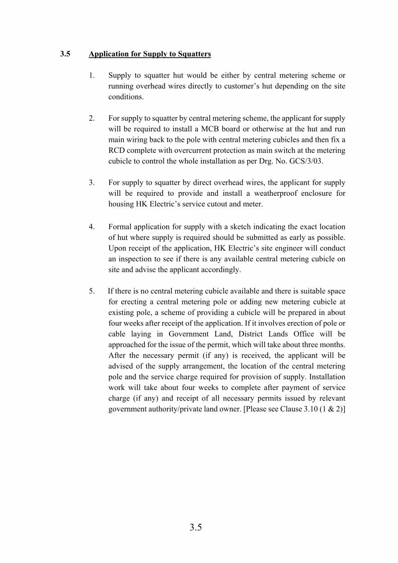
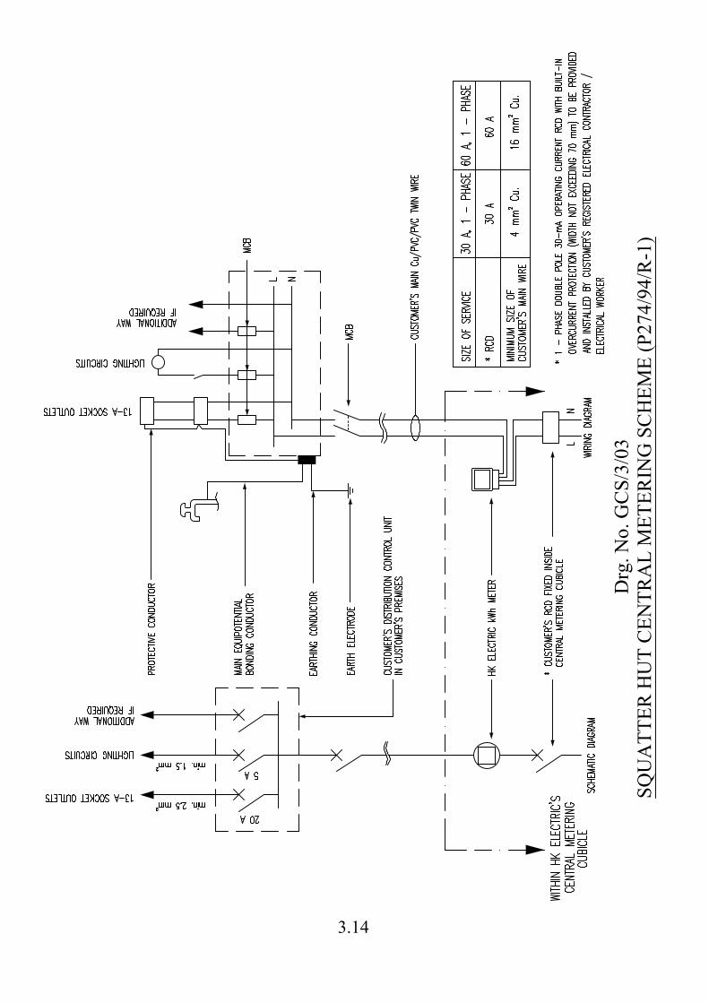
1. Supply to squatter hut would be either by central metering scheme or running overhead wires directly to customer’s hut depending on the site conditions.
2. For supply to squatter by central metering scheme, the applicant for supply will be required to install a MCB board or otherwise at the hut and run main wiring back to the pole with central metering cubicles and then fix a RCD complete with overcurrent protection as main switch at the metering cubicle to control the whole installation as per Drg. No. GCS/3/03.
3. For supply to squatter by direct overhead wires, the applicant for supply
will be required to provide and install a weatherproof enclosure for housing HK Electric’s service cutout and meter.
4. Formal application for supply with a sketch indicating the exact location
of hut where supply is required should be submitted as early as possible. Upon receipt of the application, HK Electric’s site engineer will conduct an inspection to see if there is any available central metering cubicle on site and advise the applicant accordingly.
5. If there is no central metering cubicle available and there is suitable space for erecting a central metering pole or adding new metering cubicle at existing pole, a scheme of providing a cubicle will be prepared in about four weeks after receipt of the application. If it involves erection of pole or cable laying in Government Land, District Lands Office will be approached for the issue of the permit, which will take about three months. After the necessary permit (if any) is received, the applicant will be advised of the supply arrangement, the location of the central metering pole and the service charge required for provision of supply. Installation work will take about four weeks to complete after payment of service charge (if any) and receipt of all necessary permits issued by relevant government authority/private land owner. [Please see Clause 3.10 (1 & 2)]

3.6
6. If there is no central metering cubicle available and there is no suitable space for adding a central metering cubicle, a scheme for providing supply by direct overhead wires will be prepared. The applicant will be advised of the supply arrangement, the location of the weatherproof enclosure to be provided and installed and the service charge (if required) for provision of supply. The installed weatherproof enclosure will be inspected by HK Electric after payment of the service charge/deposit. Installation work will take about four weeks to complete after payment of service charge (if any) and deposit and acceptance of the weatherproof enclosure. [Please see Clause 3.10 (1 & 2)]
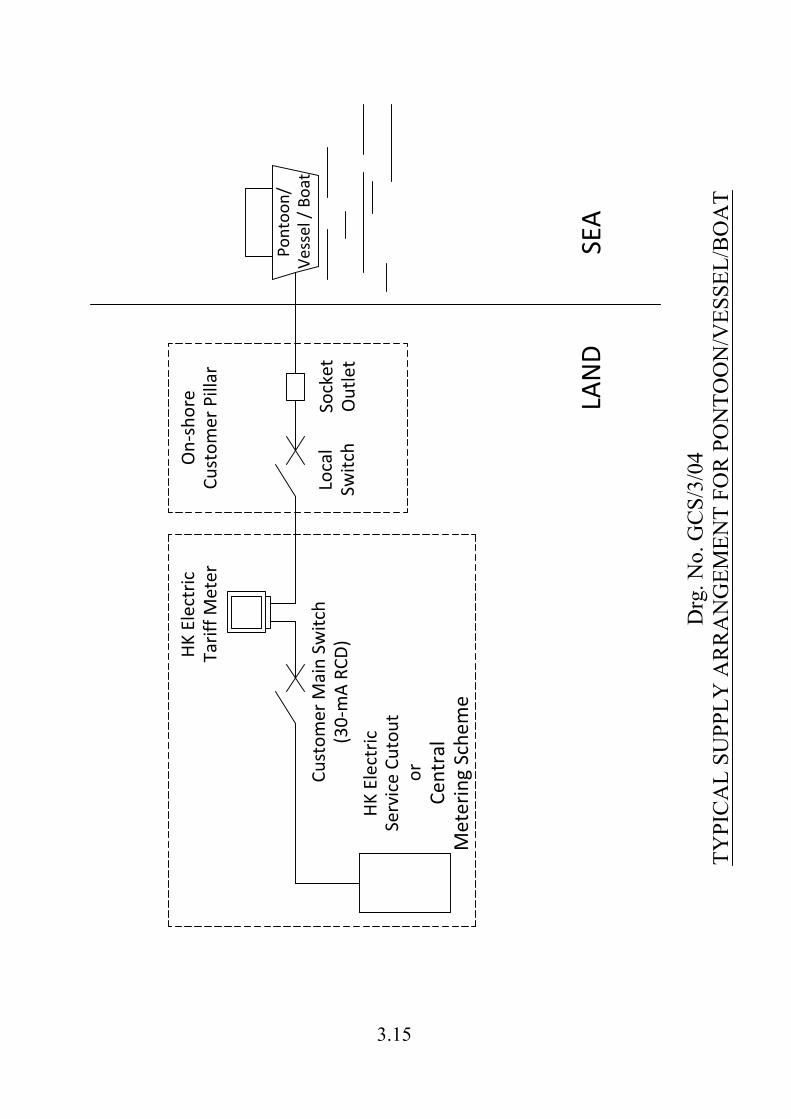
3.6 Application for Supply to Pontoon/Vessel/Boat
1. Customer shall install a socket outlet of appropriate rating inside a weatherproof enclosure erected on shore for supplying electricity to pontoon/vessel/boat.
2. Supply would normally be provided by HK Electric LV service
cable/cutout or central metering scheme.
3. The customer main switch shall be of a RCD of 30-mA operating current. It should be equipped with overcurrent protection and adequate short circuit breaking capacity.
4. The supply arrangement is shown in Drg. No. GCS/3/04.
5. Formal application for supply with a sketch indicating the exact location of
the weatherproof enclosure and pontoon/vessel/boat where supply is required should be submitted as early as possible. Upon receipt of the application, HK Electric’s site engineer will conduct an inspection to see how to provide the supply and advise the applicant accordingly.
3.7 Application for Supply to Hawker Stalls
1. Applicant for supply to a stall should submit to HK Electric the following
documents: a. A copy of his licence issued by Food and Environmental Hygiene
Department (FEHD)
3.7
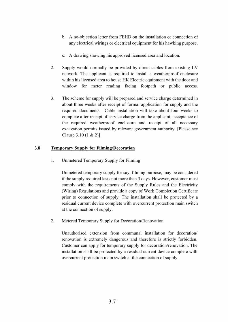
b. A no-objection letter from FEHD on the installation or connection of
any electrical wirings or electrical equipment for his hawking purpose.
c. A drawing showing his approved licensed area and location.
2. Supply would normally be provided by direct cables from existing LV network. The applicant is required to install a weatherproof enclosure within his licensed area to house HK Electric equipment with the door and window for meter reading facing footpath or public access.
3. The scheme for supply will be prepared and service charge determined in about three weeks after receipt of formal application for supply and the required documents. Cable installation will take about four weeks to complete after receipt of service charge from the applicant, acceptance of the required weatherproof enclosure and receipt of all necessary excavation permits issued by relevant government authority. [Please see Clause 3.10 (1 & 2)]
3.8 Temporary Supply for Filming/Decoration 1. Unmetered Temporary Supply for Filming Unmetered temporary supply for say, filming purpose, may be considered
if the supply required lasts not more than 3 days. However, customer must comply with the requirements of the Supply Rules and the Electricity (Wiring) Regulations and provide a copy of Work Completion Certificate prior to connection of supply. The installation shall be protected by a residual current device complete with overcurrent protection main switch at the connection of supply.
2. Metered Temporary Supply for Decoration/Renovation Unauthorised extension from communal installation for decoration/
renovation is extremely dangerous and therefore is strictly forbidden. Customer can apply for temporary supply for decoration/renovation. The installation shall be protected by a residual current device complete with overcurrent protection main switch at the connection of supply.

3.8
3.9 Application for Transfer 1. We require one working day advance notice to process transfer of account.
For most of the cases, we accept phone application/application by electronic form available from our website www.hkelectric.com for transfer and the process can be completed the next working day. A meter reading will be taken on the specified transfer date after which the customer will be responsible for the electricity consumption of the account. In case the customer has already occupied the address for a period of time, the date of the last monthly meter reading would be used in the transfer of account. The meter reading date is shown in the monthly electricity bill.
2. The completed Application Form For Supply/Transfer can also be returned
to our Customer Centre by post or in person or by fax to 2510 7667. HK Electric will inform the customer of the deposit amount by letter.
3. No service charge is required for an application for transfer of account. 4. For details of deposit amount for a transfer of account, please call our
Customer Services Representatives at 2887 3411 during office hours. 5. When the transfer of account has been completed, the account of the
former registered customer will be closed and the deposit will normally be ready for refund.
3.10 Additional Information 1. The time scales mentioned in the above sections are for indication only and
HK Electric is not committed to provide supply by any prescribed date although every effort will be made to provide supply as early as possible.
2. The actual time needed to plan and install any plant required for provision
of a supply depends on many factors such as the network situation, the working condition on site, availability of necessary permits issued by relevant government authority/private land owner (Excavation Permit, Government Lands Permit, Hong Kong Police Force Roadworks Advice, Construction Noise Permit and written approval from private land owners), etc.
3.9
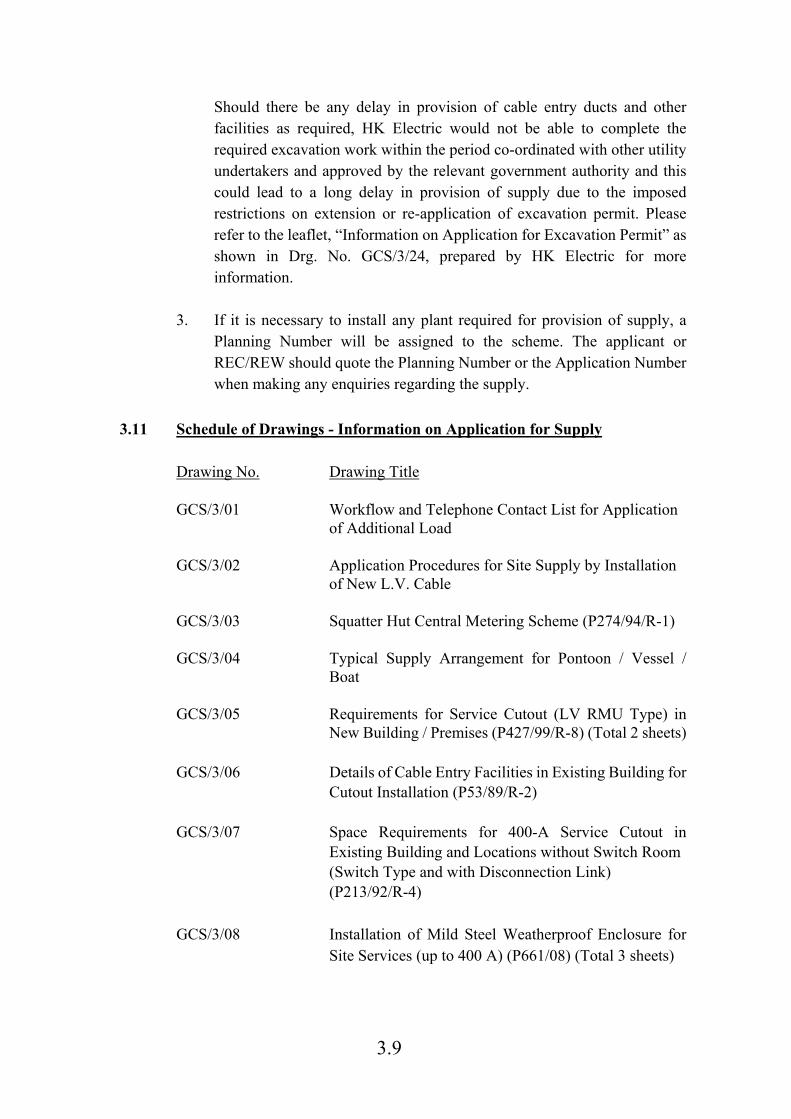
Should there be any delay in provision of cable entry ducts and other facilities as required, HK Electric would not be able to complete the required excavation work within the period co-ordinated with other utility undertakers and approved by the relevant government authority and this could lead to a long delay in provision of supply due to the imposed restrictions on extension or re-application of excavation permit. Please refer to the leaflet, “Information on Application for Excavation Permit” as shown in Drg. No. GCS/3/24, prepared by HK Electric for more information.
3. If it is necessary to install any plant required for provision of supply, a
Planning Number will be assigned to the scheme. The applicant or REC/REW should quote the Planning Number or the Application Number when making any enquiries regarding the supply.
3.11 Schedule of Drawings - Information on Application for Supply Drawing No. Drawing Title GCS/3/01 Workflow and Telephone Contact List for Application
of Additional Load GCS/3/02 Application Procedures for Site Supply by Installation
of New L.V. Cable GCS/3/03 Squatter Hut Central Metering Scheme (P274/94/R-1) GCS/3/04 Typical Supply Arrangement for Pontoon / Vessel /
Boat GCS/3/05 Requirements for Service Cutout (LV RMU Type) in
New Building / Premises (P427/99/R-8) (Total 2 sheets) GCS/3/06 Details of Cable Entry Facilities in Existing Building for
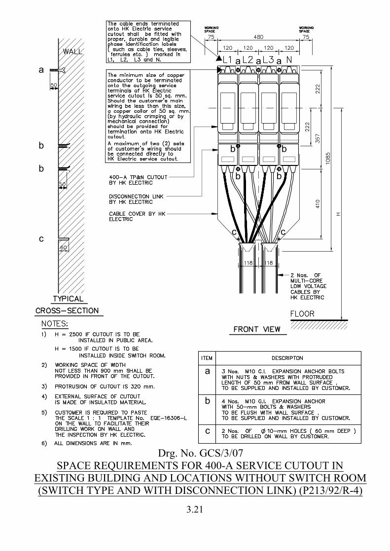
Cutout Installation (P53/89/R-2) GCS/3/07 Space Requirements for 400-A Service Cutout in
Existing Building and Locations without Switch Room (Switch Type and with Disconnection Link)
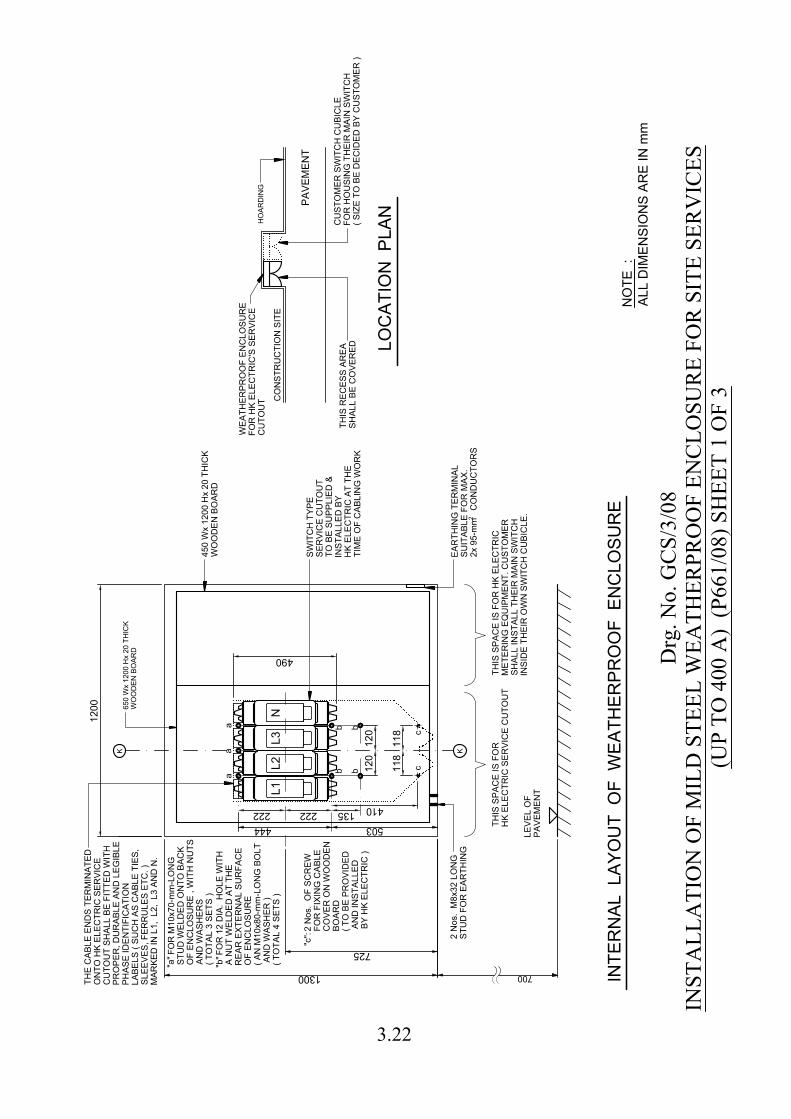
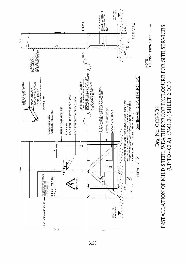
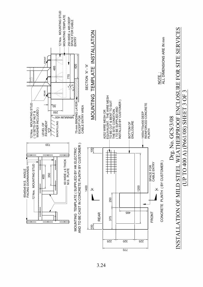
(P213/92/R-4) GCS/3/08 Installation of Mild Steel Weatherproof Enclosure for
Site Services (up to 400 A) (P661/08) (Total 3 sheets)
3.10
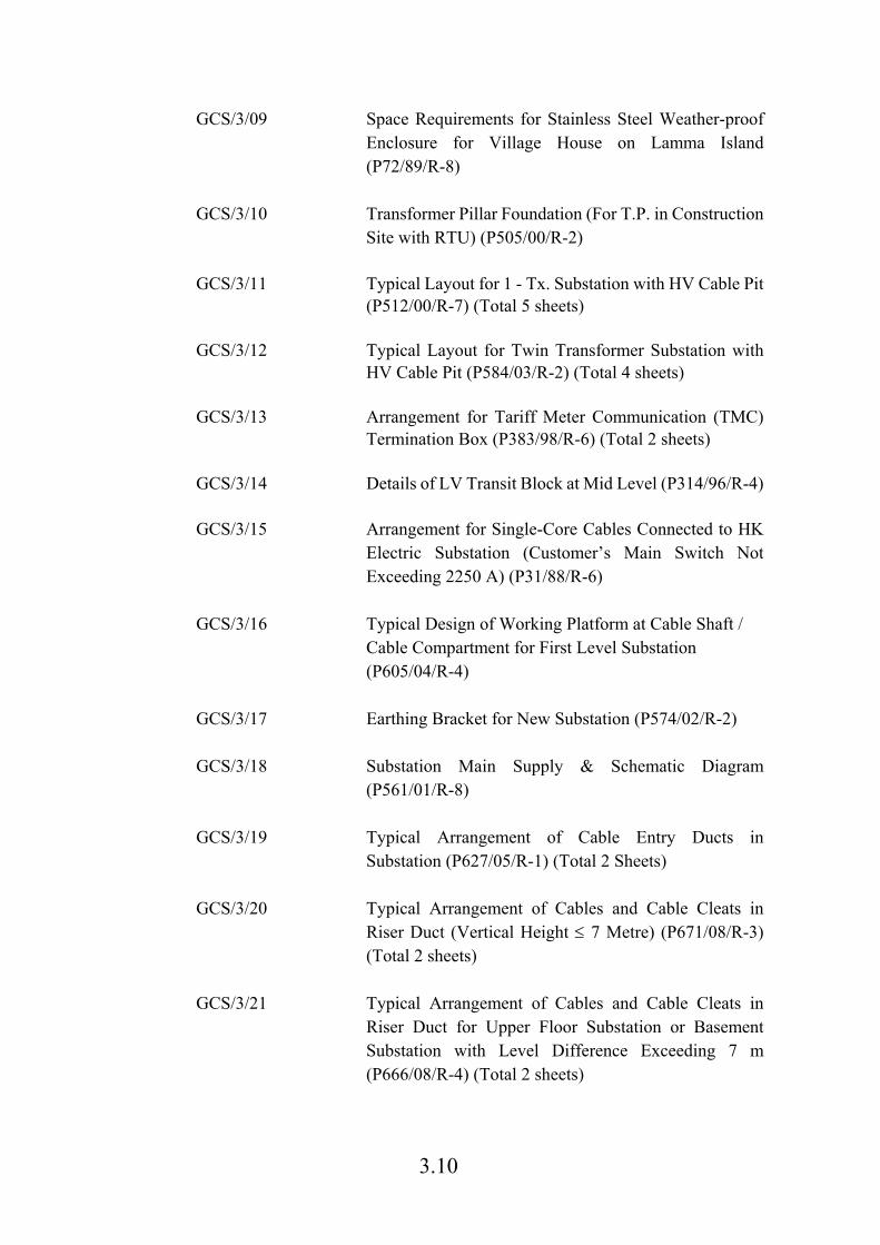
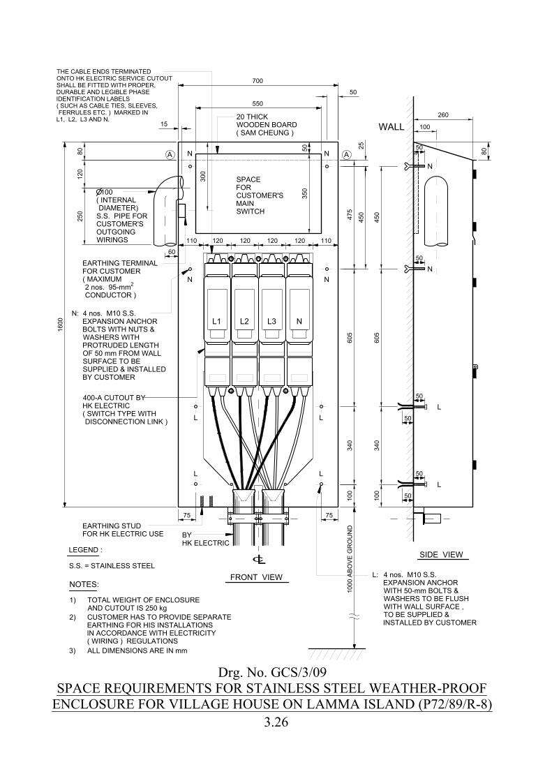
GCS/3/09 Space Requirements for Stainless Steel Weather-proof Enclosure for Village House on Lamma Island (P72/89/R-8)
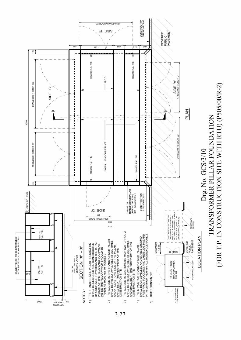
GCS/3/10 Transformer Pillar Foundation (For T.P. in Construction
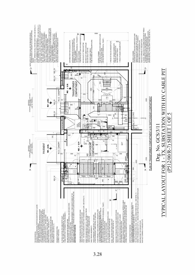
Site with RTU) (P505/00/R-2) GCS/3/11 Typical Layout for 1 - Tx. Substation with HV Cable Pit
(P512/00/R-7) (Total 5 sheets) GCS/3/12 Typical Layout for Twin Transformer Substation with
HV Cable Pit (P584/03/R-2) (Total 4 sheets) GCS/3/13 Arrangement for Tariff Meter Communication (TMC)
Termination Box (P383/98/R-6) (Total 2 sheets) GCS/3/14 Details of LV Transit Block at Mid Level (P314/96/R-4) GCS/3/15 Arrangement for Single-Core Cables Connected to HK
Electric Substation (Customer’s Main Switch Not Exceeding 2250 A) (P31/88/R-6)
GCS/3/16 Typical Design of Working Platform at Cable Shaft /
Cable Compartment for First Level Substation (P605/04/R-4)
GCS/3/17 Earthing Bracket for New Substation (P574/02/R-2) GCS/3/18 Substation Main Supply & Schematic Diagram
(P561/01/R-8) GCS/3/19 Typical Arrangement of Cable Entry Ducts in
Substation (P627/05/R-1) (Total 2 Sheets)
GCS/3/20 Typical Arrangement of Cables and Cable Cleats in Riser Duct (Vertical Height 7 Metre) (P671/08/R-3) (Total 2 sheets)
GCS/3/21 Typical Arrangement of Cables and Cable Cleats in
Riser Duct for Upper Floor Substation or Basement Substation with Level Difference Exceeding 7 m (P666/08/R-4) (Total 2 sheets)
3.11
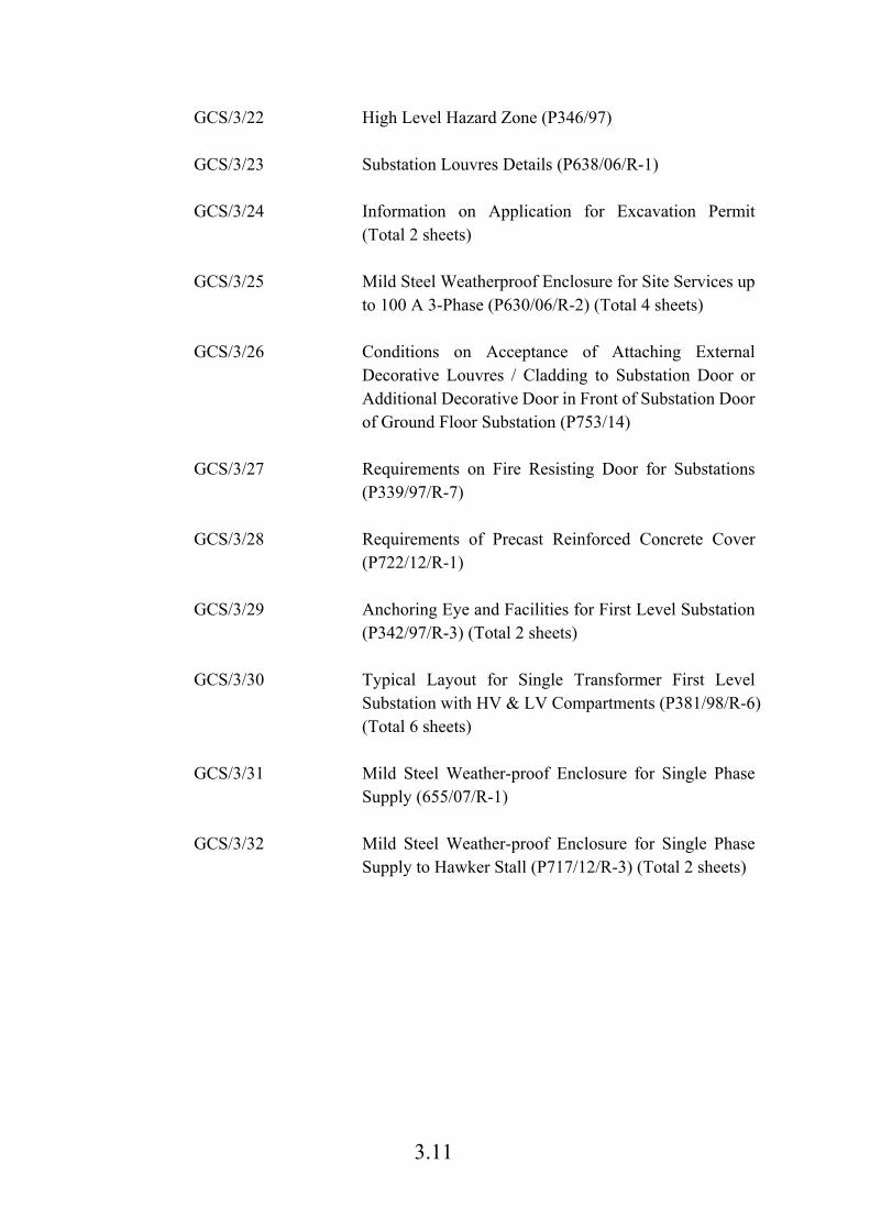
GCS/3/22 High Level Hazard Zone (P346/97)
GCS/3/23 Substation Louvres Details (P638/06/R-1) GCS/3/24 Information on Application for Excavation Permit
(Total 2 sheets) GCS/3/25 Mild Steel Weatherproof Enclosure for Site Services up
to 100 A 3-Phase (P630/06/R-2) (Total 4 sheets) GCS/3/26 Conditions on Acceptance of Attaching External
Decorative Louvres / Cladding to Substation Door or Additional Decorative Door in Front of Substation Door of Ground Floor Substation (P753/14)
GCS/3/27 Requirements on Fire Resisting Door for Substations
(P339/97/R-7) GCS/3/28 Requirements of Precast Reinforced Concrete Cover
(P722/12/R-1) GCS/3/29 Anchoring Eye and Facilities for First Level Substation
(P342/97/R-3) (Total 2 sheets) GCS/3/30 Typical Layout for Single Transformer First Level
Substation with HV & LV Compartments (P381/98/R-6) (Total 6 sheets)
GCS/3/31 Mild Steel Weather-proof Enclosure for Single Phase
Supply (655/07/R-1) GCS/3/32 Mild Steel Weather-proof Enclosure for Single Phase
Supply to Hawker Stall (P717/12/R-3) (Total 2 sheets)

Submission of ApplicationCustomer is required to submit application form and the following information as far as possible Load estimation Schematic wiring diagram Proposed service position (if installation of new supply point is required). Supply number details form
All requiredinformationsubmitted?
Preparation of Supply Scheme
Enquiry on service position service charge issue cable lead-in arrangement service cutout installation requirements latest status on application of excavation permit or private permissions situation arrange the site check of cabling facilities provided by customer
Distribution Planning Department Eastern Central Western
2843 31052843 31642843 3108General Enquiry on
enquiry on application form amount of service charge amount of deposit method of payment fix the first customer installation inspection date
Customer Centre / Application Unit
Creation of Account and Inspectionof Customer Installation
2887 3411
Enquiry on customer's installation comments on schematic wiring diagram metering equipment collection arrange the customer installation re-inspection date if required installation inspection result/report meter fixing date customer is required to submit a copy of Work Completion Certificate and C.I. 140 Form where appropriate enquiry on supply number details form technical enquiry on customer installation
Customer Installation & 2887 3455
Site checkpassed?
Enquiry on commencement date of the work service cutout and cable installation date duration of work progress of work date of completion
Construction & Maintenance DepartmentCustomer Services Representative
Installation of Cutout/Service Cable
2814 3997
Additional supply available
Remark: 1.Please contact the corresponding department or call our Electricity-By-Phone Service at telephone No. 2887 3838 if you have any queries regardingthe progress of application.
Customer Supplies Department
No
Yes
No
Yes
CUSTOMER
HK ELECTRIC
Training Department
*
Drg. No. GCS/3/01WORKFLOW AND TELEPHONE CONTACT LIST
FOR APPLICATION OF ADDITIONAL LOAD3.12
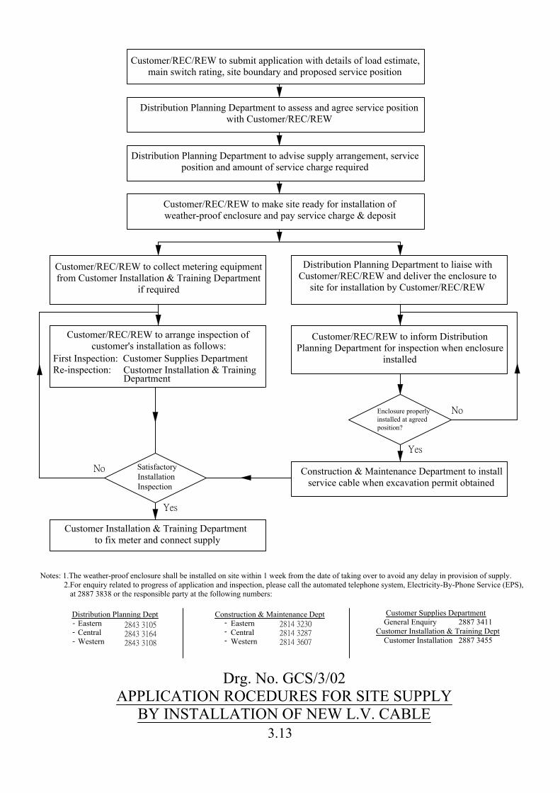
Notes: 1.The weather-proof enclosure shall be installed on site within 1 week from the date of taking over to avoid any delay in provision of supply. 2.For enquiry related to progress of application and inspection, please call the automated telephone system, Electricity-By-Phone Service (EPS), at 2887 3838 or the responsible party at the following numbers:
Customer Installation & Training Department to fix meter and connect supply
Distribution Planning Dept Eastern Central Western
Construction & Maintenance Dept Eastern Central Western
Customer Supplies Department General Enquiry 2887 3411 Customer Installation & Training Dept Customer Installation 2887 3455
NoSatisfactoryInstallationInspection
Yes
Construction & Maintenance Department to installservice cable when excavation permit obtained
Customer/REC/REW to inform DistributionPlanning Department for inspection when enclosure
installed
Customer/REC/REW to arrange inspection ofcustomer's installation as follows:
Customer/REC/REW to collect metering equipmentfrom Customer Installation & Training Department
if required
Distribution Planning Department to liaise withCustomer/REC/REW and deliver the enclosure to
site for installation by Customer/REC/REW
NoEnclosure properlyinstalled at agreedposition?
Yes
Customer/REC/REW to make site ready for installation ofweather-proof enclosure and pay service charge & deposit
Distribution Planning Department to advise supply arrangement, serviceposition and amount of service charge required
Distribution Planning Department to assess and agree service positionwith Customer/REC/REW
Customer/REC/REW to submit application with details of load estimate,main switch rating, site boundary and proposed service position
First Inspection: Customer Supplies DepartmentRe-inspection: Customer Installation & Training
Department
---
2843 3105
2843 3164
2843 3108
2814 3230
2814 3287
2814 3607
---
Drg. No. GCS/3/02APPLICATION ROCEDURES FOR SITE SUPPLY
BY INSTALLATION OF NEW L.V. CABLE3.13
Drg
. No.
GC
S/3/
03SQ
UA
TTER
HU
T C
ENTR
AL
MET
ERIN
G S
CH
EME
(P27
4/94
/R-1
)
3.14
Pont
oon/
Vess
el /
Boat
Sock
etO
utle
tLo
cal
Switc
hOn-
shor
eCu
stom
er P
illar
HK E
lect
ricTa
riff M
eter
HK E
lect
ricSe
rvic
e Cu
tout
orCe
ntra
lM
eter
ing
Sche
me
Cust
omer
Mai
n Sw
itch
(30-
mA
RCD)
LAN
DSE
A
Drg
. No.
GC
S/3/
04TY
PIC
AL
SUPP
LY A
RR
AN
GEM
ENT
FOR
PO
NTO
ON
/VES
SEL/
BO
AT
3.15
65
0
20
35
72
5
65
20
50
L1 L2 L3 N
FU
SE
WA
Y N
o. 1
FU
SE
WA
Y N
o. 2
FU
SE
WA
Y N
o. 3
CONNECTION FOR CUSTOMER'S WIRING
FLOOR
WEIGHT OF 160 kg
560
EARTHING
CONNECTION
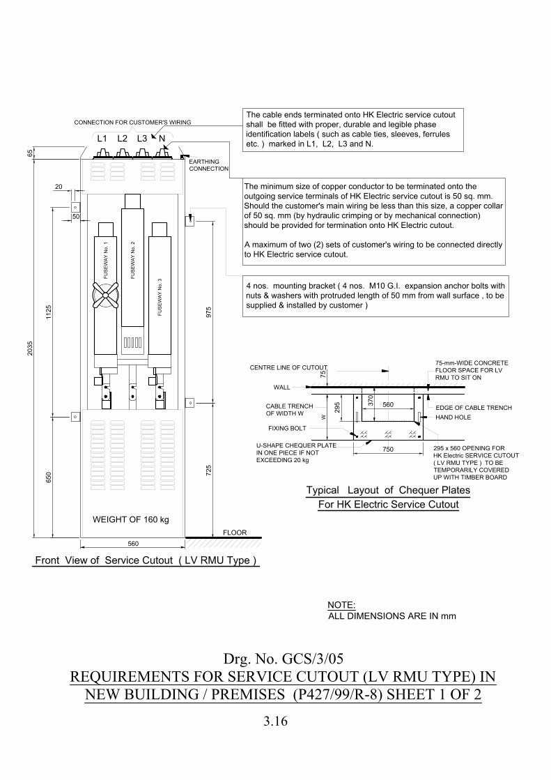
Front View of Service Cutout ( LV RMU Type )
The cable ends terminated onto HK Electric service cutout
shall be fitted with proper, durable and legible phase
identification labels ( such as cable ties, sleeves, ferrules
etc. ) marked in L1, L2, L3 and N.
The minimum size of copper conductor to be terminated onto the
outgoing service terminals of HK Electric service cutout is 50 sq. mm.
Should the customer's main wiring be less than this size, a copper collar
of 50 sq. mm (by hydraulic crimping or by mechanical connection)
should be provided for termination onto HK Electric cutout.
A maximum of two (2) sets of customer's wiring to be connected directly
to HK Electric service cutout.
4 nos. mounting bracket ( 4 nos. M10 G.I. expansion anchor bolts with
nuts & washers with protruded length of 50 mm from wall surface , to be
supplied & installed by customer )
11
25
97
5
750
W
FIXING BOLT
HAND HOLE
CABLE TRENCH
OF WIDTH W
CENTRE LINE OF CUTOUT
WALL
75
560
37
0
EDGE OF CABLE TRENCH
75-mm-WIDE CONCRETE
FLOOR SPACE FOR LV
RMU TO SIT ON
29
5
295 x 560 OPENING FOR
HK Electric SERVICE CUTOUT
( LV RMU TYPE ) TO BE
TEMPORARILY COVERED
UP WITH TIMBER BOARD
Typical Layout of Chequer Plates
For HK Electric Service Cutout
U-SHAPE CHEQUER PLATE
IN ONE PIECE IF NOT
EXCEEDING 20 kg
Drg. No. GCS/3/05REQUIREMENTS FOR SERVICE CUTOUT (LV RMU TYPE) IN
NEW BUILDING / PREMISES (P427/99/R-8) SHEET 1 OF 2
NOTE:
ALL DIMENSIONS ARE IN mm
3.16
L1
L2
L3
NL1
L2
L3
NL1
L2
L3
N
2100
800
SW
IT
CH
RO
OM
CA
BLE
T
RE
NC
H
BU
IL
DIN
G
BO
UN
DA
RY
PA
VE
ME
NT
760
Section
750
750
750
370
W
CA
BL
E
TR
EN
CH
OF
D
EP
TH
80
0
SW
IT
CH
RO
OM
PA
VE
ME
NT
BU
IL
DIN
G
BO
UN
DA
RY
N N
os. O
F
15
0 D
IA
. C
AB
LE
EN
TR
Y D
UC
TS
(M
AX
. 2
L
AY
ER
S)
SE
RV
IC
E
CU
TO
UT
EA
CH
O
F
16
0 kg
WE
IG
HT
75
07
50
75
0
DO
OR
N
OT
LE
SS
T
HA
N
23
00
H
IG
H A
ND
75
0 W
ID
E
(IN
TE
RN
AL
ME
AS
UR
EM
EN
T)
Pa
rt o
f G
ro
un
d F
lo
or P
la
n o
f a
T
yp
ica
l B
uild
in
g
Cu
sto
me
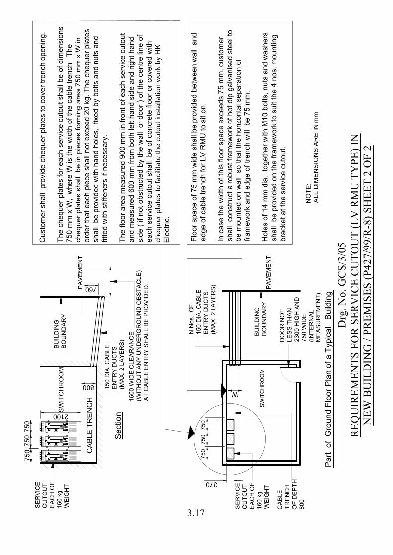
r sh
all p
ro
vid
e ch
eq
ue
r p
la
te
s to
co
ve
r tre
nch
o
pe
nin
g.
Th
e ch
eq
ue
r p
la
te
s fo
r e
ach
se
rvice
cu
to
ut sh
all b
e o
f d
im
en
sio
ns
75
0 m
m x W
, w
he
re
W
is th
e w
id
th
o
f th
e ca
ble
tre
nch
. T
he
ch
eq
ue
r p
la
te
s sh
all b
e in
p
ie
ce
s fo
rm
in
g a
re
a 7
50
m
m x W
in
ord
er th
at e
ach
p
ie
ce
sh
all n
ot e
xce
ed
2
0 kg
. T
he
ch
eq
ue
r p
la
te
s
sh
all b
e p
ro
vid
ed
w
ith
h
an
d h
ole
s, fixe
d b
y b
olts a
nd
n
uts a
nd
fitte
d w
ith
stiffe
ne
rs if n
ece
ssa
ry.
Th
e flo
or a
re
a m
ea
su
re
d 9
00
m
m in
fro
nt o
f e
ach
se
rvice
cu
to
ut
an
d m
ea
su
re
d 6
00
m
m fro
m b
oth
le
ft h
an
d sid
e a
nd
rig
ht h
an
d
sid
e ( if n
ot o
bstru
cte
d b
y th
e w
all o
r d
oo
r ) o
f th
e ce
ntre
lin
e o
f
ea
ch
se
rvice
cu
to
ut sh
all b
e o
f co
ncre
te
flo
or o
r co
ve
re
d w
ith
ch
eq
ue
r p
la
te
s to
fa
cilita
te
th
e cu
to
ut in
sta
lla
tio
n w
ork b
y H
K
Ele
ctric.
Flo
or sp
ace
o
f 7
5 m
m w
id
e sh
all b
e p
ro
vid
ed
b
etw
ee
n w
all a
nd
ed
ge
o
f ca
ble
tre
nch
fo
r L
V R
MU
to
sit o
n.
In
ca
se
th
e w
id
th
o
f th
is flo
or sp
ace
e
xce
ed
s 7
5 m
m, cu
sto
me
r
sh
all co
nstru
ct a
ro
bu
st fra
me
wo
rk o
f h
ot d
ip
g
alva
nise
d ste
el to
be
m
ou
nte
d o
n w
all so
th
at th
e h
orizo
nta
l se
pa
ra
tio
n o
f
fra
me
wo
rk a
nd
e
dg
e o
f tre
nch
w
ill b
e 7
5 m
m.
Ho
le
s o
f 1
4 m
m d
ia
. to
ge
th
er w
ith
M
10
b
olts, n
uts a
nd
w
ash
ers
sh
all b
e p
ro
vid
ed
o
n th
e fra
me
wo
rk to
su
it th
e 4
n
os. m
ou
ntin
g
bra
cke
t a
t th
e se
rvice
cu
to
ut.
16
00
W
ID
E C
LE
AR
AN
CE
(W
IT
HO
UT
A
NY
U
ND
ER
GR
OU
ND
O
BS
TA
CL
E)
AT
C
AB
LE
E
NT
RY
S
HA
LL
B
E P
RO
VID
ED
.
SE
RV
IC
E
CU
TO
UT
EA
CH
O
F
16
0 kg
WE
IG
HT
15
0 D
IA
. C
AB
LE
EN
TR
Y D
UC
TS
(M
AX
. 2
L
AY
ER
S)
Drg
. No.
GC
S/3/
05R
EQU
IREM
ENTS
FO
R S
ERV
ICE
CU
TOU
T (L
V R
MU
TY
PE) I
NN
EW B
UIL
DIN
G /
PREM
ISES
(P42
7/99
/R-8
) SH
EET
2 O
F 2
NO
TE
:
AL
L D
IM
EN
SIO
NS
A
RE
IN
m
m
3.17
3.18
Notes for Drawing No. GCS/3/05 1. This drawing shows the typical layout of cable entry facilities in buildings where
there is no underground obstacles. All dimensions shown in this drawing are in mm (millimetre).
2. Reinstatement of excavation surfaces required for provision of cable entry facilities
and cable laying work by The Hongkong Electric Co. Ltd. 香港電燈有限公司 within the building lot boundary shall be the responsibility of customers.
3. The cable entry facilities shall be sealed properly by customers against ingress of
water to the switchroom and other parts of the building during the excavation work by customers and after HK Electric's new cables are installed.
4. All excavation work by customers shall be carried out within the building lot
boundary. It is unlawful to excavate in public road and footway outside the building lot boundary without prior approval of the Government Highways Department.
5. A minimum clearance space of 900 mm for the full width and in front of HK
Electric's service cutouts and customer's switchgear shall be provided. 6. Where there is spare space on wall of switchroom for contingency service cutout
(please refer to the returned marked-up copy of Ground Floor Plan), the spare space shall be painted in red with an engraved label not less than 150 mm wide x 75 mm high stating
"SPACE RESERVED FOR HK ELECTRIC'S CONTINGENCY SERVICE CUTOUT" with Chinese translation,「應 急 熔 斷 器 之 預 留 空 間 」 being
securely fixed on the wall space. 7. Normally, HK Electric will install service cutouts at the positions furthest from the
cable entry ducts. Spare spaces for contingency service cutouts will be the closest from the cable entry ducts.
8. The number of cable entry ducts and width of cable trench shall be provided
according to the following table, unless otherwise specified.
No. of Service Cutout Spaces (including spare, if any)
No. of Cable Entry Ducts (N)
Width of Cable Trench (W)
1 4 500 mm 2 6 600 mm 3 8 750 mm

3.19
Notes for Drawing No. GCS/3/05 9. A minimum clearance of 1600 mm wide (without any underground obstacle)
immediately in front of the cable entries should be provided for cable installation. Where necessary the architect shall be responsible for clearing underground obstacles with other utility companies before hand-over of the switchroom to HK Electric for cable installation.
10. The door of switchroom shall not be less than 750 mm wide by 2300 mm high
measured clear of obstacles.
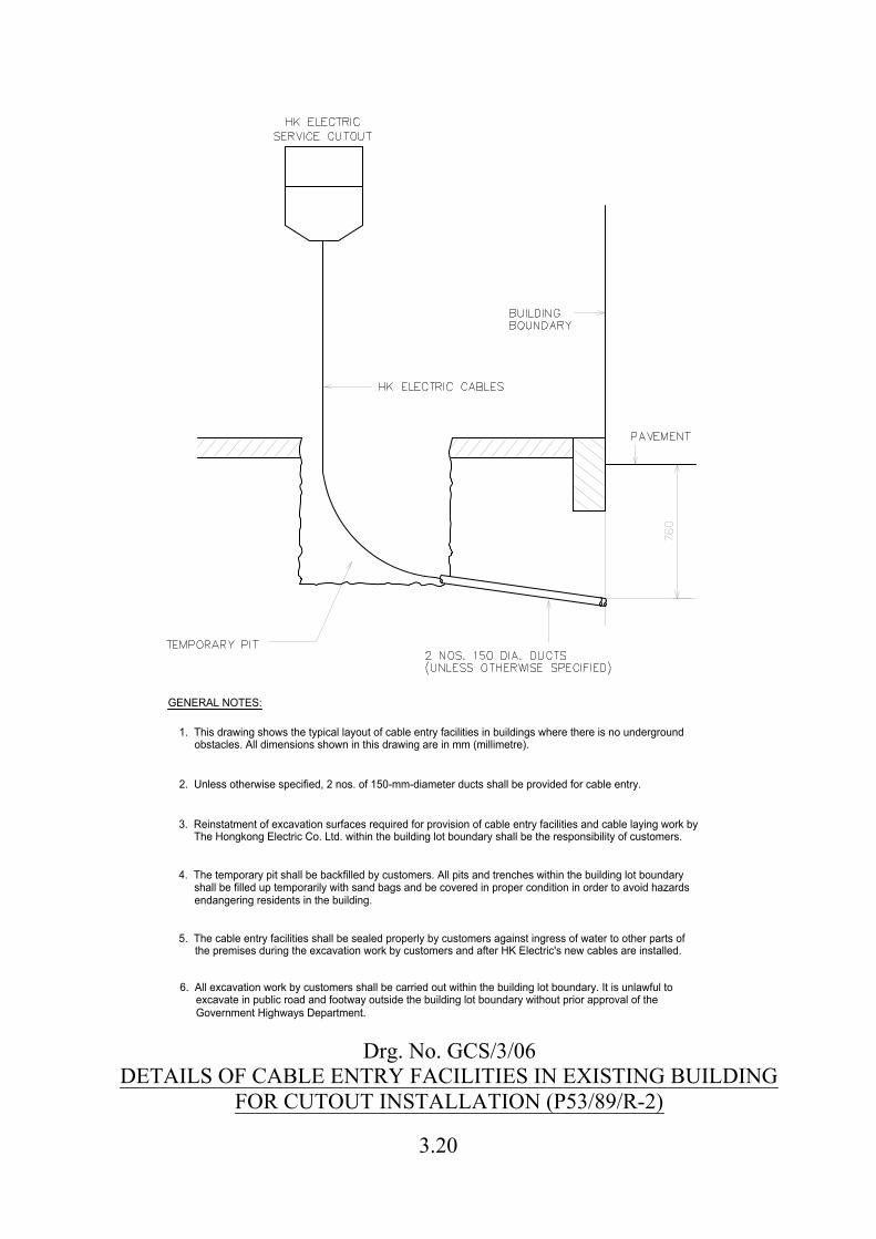
GENERAL NOTES:
obstacles. All dimensions shown in this drawing are in mm (millimetre).
excavate in public road and footway outside the building lot boundary without prior approval of theGovernment Highways Department.
shall be filled up temporarily with sand bags and be covered in proper condition in order to avoid hazardsendangering residents in the building.
The Hongkong Electric Co. Ltd. within the building lot boundary shall be the responsibility of customers.
1. This drawing shows the typical layout of cable entry facilities in buildings where there is no underground
2. Unless otherwise specified, 2 nos. of 150-mm-diameter ducts shall be provided for cable entry.
3. Reinstatment of excavation surfaces required for provision of cable entry facilities and cable laying work by
4. The temporary pit shall be backfilled by customers. All pits and trenches within the building lot boundary
5. The cable entry facilities shall be sealed properly by customers against ingress of water to other parts of
6. All excavation work by customers shall be carried out within the building lot boundary. It is unlawful to
the premises during the excavation work by customers and after HK Electric's new cables are installed.
Drg. No. GCS/3/06DETAILS OF CABLE ENTRY FACILITIES IN EXISTING BUILDING
FOR CUTOUT INSTALLATION (P53/89/R-2)
3.20
a
b b
a a
b b
c c
a
b
b
c
a
b
c
Drg. No. GCS/3/07SPACE REQUIREMENTS FOR 400-A SERVICE CUTOUT IN
EXISTING BUILDING AND LOCATIONS WITHOUT SWITCH ROOM(SWITCH TYPE AND WITH DISCONNECTION LINK) (P213/92/R-4)
3.21
1200
490
135
120
222
118
118
410
IN
TE
RN
AL
L
AY
OU
T O
F W
EA
TH
ER
PR
OO
F E
NC
LO
SU
RE
2
L1
L2
L3
N
2 N
os. M
8x3
2 L
ON
G
ST
UD
F
OR
E
AR
TH
IN
G
TH
IS
S
PA
CE
IS
F
OR
HK
E
LE
CT
RIC
S
ER
VIC
E C
UT
OU
T
EA
RT
HIN
G T
ER
MIN
AL
SU
IT
AB
LE
F
OR
M
AX
.
2x 9
5-m
m C
ON
DU
CT
OR
S
"a
" F
OR
M
10
x7
0-m
m-L
ON
G
ST
UD
W
EL
DE
D O
NT
O B
AC
K
OF
E
NC
LO
SU
RE
, W
IT
H N
UT
S
AN
D W
AS
HE
RS
( T
OT
AL
3
S
ET
S )
"b
"
TH
IS
S
PA
CE
IS
F
OR
H
K E
LE
CT
RIC
ME
TE
RIN
G E
QU
IP
ME
NT
. C
US
TO
ME
R
SH
AL
L IN
ST
AL
L T
HE
IR
M
AIN
S
WIT
CH
IN
SID
E T
HE
IR
O
WN
S
WIT
CH
C
UB
IC
LE
.
KK
"c":
65
0 W
x 1
20
0 H
x 2
0 T
HIC
K
WO
OD
EN
B
OA
RD
45
0 W
x 1
20
0 H
x 2
0 T
HIC
K
WO
OD
EN
B
OA
RD
LE
VE
L O
F
PA
VE
ME
NT
2
N
os. O
F S
CR
EW
F
OR
F
IX
IN
G C
AB
LE
C
OV
ER
O
N W
OO
DE
N
B
OA
RD
( T
O B
E P
RO
VID
ED
A
ND
IN
ST
AL
LE
D
B
Y H
K E
LE
CT
RIC
)
F
OR
1
2 D
IA
. H
OL
E W
IT
H
A N
UT
W
EL
DE
D A
T T
HE
RE
AR
E
XT
ER
NA
L S
UR
FA
CE
OF
E
NC
LO
SU
RE
( A
N M
10
x8
0-m
m-L
ON
G B
OL
T
A
ND
W
AS
HE
R )
( T
OT
AL
4
S
ET
S )
TH
E C
AB
LE
E
ND
S T
ER
MIN
AT
ED
ON
TO
H
K E
LE
CT
RIC
S
ER
VIC
E
CU
TO
UT
S
HA
LL
B
E F
IT
TE
D W
IT
H
PR
OP
ER
, D
UR
AB
LE
A
ND
L
EG
IB
LE
PH
AS
E ID
EN
TIF
IC
AT
IO
N
LA
BE
LS
( S
UC
H A
S C
AB
LE
T
IE
S,
SL
EE
VE
S, F
ER
RU
LE
S E
TC
. )
MA
RK
ED
IN
L
1, L
2, L
3 A
ND
N
.
SW
IT
CH
T
YP
E
SE
RV
IC
E C
UT
OU
T
TO
B
E S
UP
PL
IE
D &
IN
ST
AL
LE
D B
Y
HK
E
LE
CT
RIC
A
T T
HE
TIM
E O
F C
AB
LIN
G W
OR
K
120
222
444 503
725
1300
HO
AR
DIN
G
PA
VE
ME
NT
LO
CA
TIO
N P
LA
N
TH
IS
R
EC
ES
S A
RE
A
SH
AL
L B
E C
OV
ER
ED
CU
ST
OM
ER
S
WIT
CH
C
UB
IC
LE
FO
R H
OU
SIN
G T
HE
IR
M
AIN
S
WIT
CH
( S
IZ
E T
O B
E D
EC
ID
ED
B
Y C
US
TO
ME
R )
WE
AT
HE
RP
RO
OF
E
NC
LO
SU
RE
FO
R H
K E
LE
CT
RIC
'S
S
ER
VIC
E
CU
TO
UT
CO
NS
TR
UC
TIO
N S
IT
E
700
aa
a
cc
b
bb
b
Drg
. No.
GC
S/3/
08IN
STA
LLA
TIO
N O
F M
ILD
STE
EL W
EATH
ERPR
OO
F EN
CLO
SUR
E FO
R S
ITE
SER
VIC
ES(U
P TO
400
A)
(P66
1/08
) SH
EET
1 O
F 3
NO
TE
:
AL
L D
IM
EN
SIO
NS
A
RE
IN
m
m
3.22
1200
72
0
20
02
00
26
0
41
0
300
12
00
32
0
700
FR
ON
T V
IE
W
SID
E V
IE
W
GE
NE
RA
L C
ON
ST
RU
CT
IO
N
FR
ON
TR
EA
R
LE
VE
L O
F
PA
VE
ME
NT
LE
VE
L O
F
PA
VE
ME
NT
OW
NE
RS
HIP
O
F T
HIS
E
NC
LO
SU
RE
BE
LO
NG
S T
O T
HE
U
SE
R,
CO
MP
AN
Y N
AM
E:
:
,
20
0x2
00
P
ER
SP
EX
FO
R M
ET
ER
R
EA
DIN
G
KK
!D
AN
GE
R!
2 P
IE
CE
S O
F
20
-m
m-T
HIC
K
WO
OD
EN
B
OA
RD
IN
SID
E E
NC
LO
SU
RE
2 N
os. C
AB
LE
CL
AM
P W
IT
H M
10
FIX
IN
G B
OL
T &
NU
T
UP
PE
R C
OM
PA
RT
ME
NT
&
LO
WE
R F
RA
ME
WO
RK
T
O B
E
TR
AN
SP
OR
TE
D S
EP
AR
AT
EL
Y
AN
D A
SS
EM
BL
ED
B
Y C
US
TO
ME
R
ON
S
IT
E U
SIN
G 8
S
ET
S O
F
M1
2 B
OL
TS
&
N
UT
S
2 N
os. C
AB
LE
C
LA
MP
F
OR
H
K E
LE
CT
RIC
CA
BL
E W
IT
H M
10
F
IX
IN
G B
OL
T &
N
UT
DE
MO
UN
TA
BL
E
60
x6
0x6
M
.S
. A
NG
LE
60
x6
0x6
E
ND
P
LA
TE
S
OF
M
.S
. A
NG
LE
12
D
IA
. H
OL
ES
WIT
H M
10
B
OL
TS
&
N
UT
S
DE
TA
IL
'A
'
UP
PE
R C
OM
PA
RT
ME
NT
2 P
IE
CE
S O
F D
EM
OU
NT
AB
LE
6
0x6
0x6
M
.S
. A
NG
LE
W
IT
H
EN
D P
LA
TE
( U
PP
ER
&
L
OW
ER
) ( S
EE
D
ET
AIL
'A
' )
TO
P
RO
VID
E A
3
00
W
ID
E O
PE
NIN
G T
O A
LL
OW
S
LO
T-IN
OF
H
K E
LE
CT
RIC
C
AB
LE
S ( F
RO
NT
O
NL
Y )
30
0
1300
60
x6
0x6
M
.S
. A
NG
LE
LO
WE
R F
RA
ME
WO
RK
HO
LE
F
OR
H
K E
LE
CT
RIC
P
AD
L
OC
K
HO
LE
F
OR
C
US
TO
ME
R P
AD
L
OC
K
LO
CK
B
AR
LA
BE
L O
F O
WN
ER
SH
IP
60
650 Drg
. No.
GC
S/3/
08IN
STA
LLA
TIO
N O
F M
ILD
STE
EL W
EATH
ERPR
OO
F EN
CLO
SUR
E FO
R S
ITE
SER
VIC
ES (U
P TO
400
A)
(P66
1/08
) SH
EET
2 O
F 3
NO
TE
:
AL
L D
IM
EN
SIO
NS
A
RE
IN
m
m
3.23
40
0
35
0
225
770
12
00
485
14
00
10
01
00
25
0
720
48
5
77
0
250
42
0
60
x6
0x6
M
.S
. A
NG
LE
FA
CIN
G D
OW
NW
AR
DS
60
W
ID
E x 6
T
HIC
K
M.S
. P
LA
TE
'X' 'X'
SP
AC
E F
OR
CA
BL
E E
NT
RY
14
00
x7
70
x4
00
D
EE
P
RE
IN
FO
RC
ED
C
ON
CR
ET
E
PL
IN
TH
CO
NC
RE
TE
P
LIN
TH
( B
Y C
US
TO
ME
R )
BO
TT
OM
O
F
EN
CL
OS
UR
E
MO
UN
TIN
G T
EM
PL
AT
E IN
ST
AL
LA
TIO
N
SE
CT
IO
N 'X
' - 'X
'
LE
VE
L O
F
PA
VE
ME
NT
RE
AR
FR
ON
T
75
-m
m B
IN
DIN
G L
AY
ER
EX
CE
PT
F
OR
CA
BL
E E
NT
RY
A
RE
A
12
N
os. M
OU
NT
IN
G S
TU
D
( 1
2 S
ET
S O
F N
UT
&
W
AS
HE
R IN
CL
UD
ED
)
( T
O B
E S
UP
PL
IE
D A
ND
IN
ST
AL
LE
D B
Y C
US
TO
ME
R )
A2
52
W
IR
E M
ES
H O
R
EQ
UIV
AL
EN
T. T
HE
W
IR
E M
ES
H
TO
B
E C
UT
&
B
EN
T T
O S
UIT
TH
E S
IT
E C
ON
DIT
IO
N.
MO
UN
TIN
G T
EM
PLA
TE
( S
UP
PLIE
D B
Y H
K E
LE
CT
RIC
A
ND
T
O B
E C
AS
T IN
C
ON
CR
ET
E P
LIN
TH
B
Y C
US
TO
ME
R )
RE
AR
FR
ON
T
25
0 W
ID
E x 4
85
D
EE
P
SP
AC
E F
OR
C
AB
LE
EN
TR
Y
320 225
37
5
MO
UN
TIN
G T
EM
PL
AT
E
12
N
os. M
OU
NT
IN
G S
TU
D
BA
CK
FIL
LIN
G
MINIMUM 400
12
N
os. M
OU
NT
IN
G S
TU
D
50
Drg
. No.
GC
S/3/
08IN
STA
LLA
TIO
N O
F M
ILD
STE
EL W
EATH
ERPR
OO
F EN
CLO
SUR
E FO
R S
ITE
SER
VIC
ES(U
P TO
400
A) (
P661
/08)
SH
EET
3 O
F 3
NO
TE
:
AL
L D
IM
EN
SIO
NS
A
RE
IN
m
m
3.24
3.25
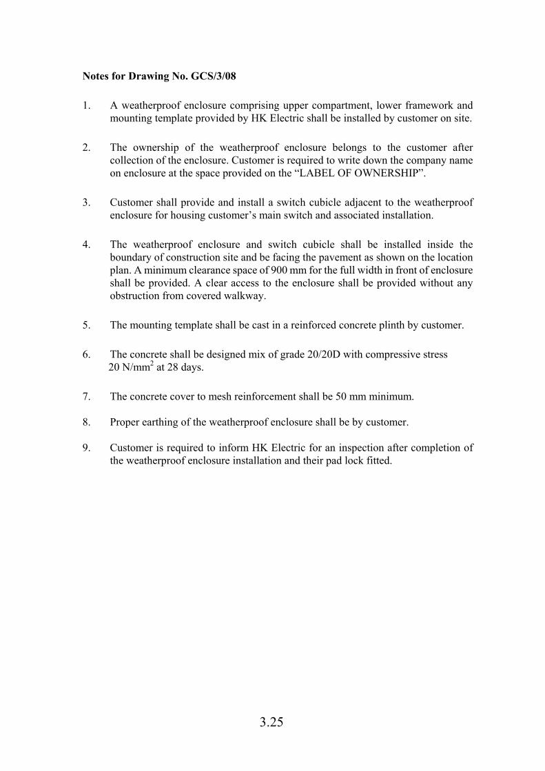
Notes for Drawing No. GCS/3/08
1. A weatherproof enclosure comprising upper compartment, lower framework and
mounting template provided by HK Electric shall be installed by customer on site.
2. The ownership of the weatherproof enclosure belongs to the customer after
collection of the enclosure. Customer is required to write down the company name on enclosure at the space provided on the “LABEL OF OWNERSHIP”.
3. Customer shall provide and install a switch cubicle adjacent to the weatherproof
enclosure for housing customer’s main switch and associated installation.
4. The weatherproof enclosure and switch cubicle shall be installed inside the
boundary of construction site and be facing the pavement as shown on the location plan. A minimum clearance space of 900 mm for the full width in front of enclosure shall be provided. A clear access to the enclosure shall be provided without any obstruction from covered walkway.
5. The mounting template shall be cast in a reinforced concrete plinth by customer.
6. The concrete shall be designed mix of grade 20/20D with compressive stress
20 N/mm2 at 28 days.
7. The concrete cover to mesh reinforcement shall be 50 mm minimum.
8. Proper earthing of the weatherproof enclosure shall be by customer.
9. Customer is required to inform HK Electric for an inspection after completion of
the weatherproof enclosure installation and their pad lock fitted.
120 120 120 120
1000
ABO
VE G
RO
UN
D
110 110
1600
550
700
BYHK ELECTRIC
TOTAL WEIGHT OF ENCLOSUREAND CUTOUT IS 250 kgCUSTOMER HAS TO PROVIDE SEPARATEEARTHING FOR HIS INSTALLATIONSIN ACCORDANCE WITH ELECTRICITY( WIRING ) REGULATIONS
1)
2)
NOTES:
L1 L2 L3 N
2
250
15
N
N
A
350
SPACEFORCUSTOMER'SMAINSWITCH
N
N A
4 nos. M10 S.S.EXPANSION ANCHORBOLTS WITH NUTS &WASHERS WITHPROTRUDED LENGTHOF 50 mm FROM WALLSURFACE TO BESUPPLIED & INSTALLEDBY CUSTOMER
20 THICKWOODEN BOARD( SAM CHEUNG )
400-A CUTOUT BYHK ELECTRIC( SWITCH TYPE WITH DISCONNECTION LINK )
CL
L
L
L
L
L:
100
475
25
50
260
100
SIDE VIEW
N
FRONT VIEW
WALL
50100
50
50
N
50
605
450
605
100( INTERNAL DIAMETER)S.S. PIPE FORCUSTOMER'SOUTGOINGWIRINGS
N:
EARTHING TERMINALFOR CUSTOMER( MAXIMUM 2 nos. 95-mm CONDUCTOR )
4 nos. M10 S.S.EXPANSION ANCHORWITH 50-mm BOLTS &WASHERS TO BE FLUSHWITH WALL SURFACE ,TO BE SUPPLIED &INSTALLED BY CUSTOMER
450
340
EARTHING STUDFOR HK ELECTRIC USE
300
LEGEND :
S.S. = STAINLESS STEEL
THE CABLE ENDS TERMINATEDONTO HK ELECTRIC SERVICE CUTOUTSHALL BE FITTED WITH PROPER,DURABLE AND LEGIBLE PHASEIDENTIFICATION LABELS( SUCH AS CABLE TIES, SLEEVES, FERRULES ETC. ) MARKED INL1, L2, L3 AND N.
75 75
L50
L50
50
60
80
120
80
340
ALL DIMENSIONS ARE IN mm3)
Drg. No. GCS/3/09SPACE REQUIREMENTS FOR STAINLESS STEEL WEATHER-PROOF
ENCLOSURE FOR VILLAGE HOUSE ON LAMMA ISLAND (P72/89/R-8)3.26
PLA
N
2840
150x200
R.C
. T
IE
150x200
R.C
. T
IE
BLIN
DIN
G LA
YE
R
CA
BLE
T
RE
NC
H T
O B
E B
AC
KF
ILLE
D
WIT
H S
IF
TE
D S
OIL B
Y H
K E
LE
CT
RIC
GR
OU
ND
LE
VE
L
200
1000 50
150
SE
CT
IO
N 'X
' - 'X
'
DIM
EN
SIO
NS
IN
m
m
1 )
NO
TE
S :
2 )
NOT LESS
THAN 300
SID
E 'C
'
SID
E 'A
'
SIDE 'B'
SIDE 'D'
150x200 R
.C
. T
IE
150x200 R
.C
. T
IE
150x200 R
.C
. T
IE
150x200 R
.C
. T
IE
R.C
.C
.
'X'
'X'
150
15
0
510
4700
4004001130400
1850x2300(H) DOOR D5
1730x2300(H
) D
OO
R D
4
2370x2300(H
) D
OO
R D
61500x2300(H
) D
OO
R D
7
D1
850x2300(H) DOOR
2100x2300(H
) D
OO
R D
2
150 D
IA
. U
PV
C C
AB
LE
D
UC
T
15
0 D
IA
.
UP
VC
C
AB
LE
D
UC
T
CO
VE
RE
D
PU
BL
IC
PA
VE
ME
NT
TH
E T
RA
NS
FO
RM
ER
P
ILLA
R F
OU
ND
AT
IO
N
SH
ALL B
E D
ES
IG
NE
D A
ND
C
ON
ST
RU
CT
ED
BY
C
US
TO
ME
R T
O W
IT
HS
TA
ND
T
HE
T
OT
AL
WE
IG
HT
O
F T
HE
P
ILLA
R A
ND
E
QU
IP
ME
NT
IN
SID
E T
HE
P
ILLA
R W
HIC
H S
HO
ULD
B
E
TA
KE
N A
S 10000 kg ( 10 T
ON
NE
S )
5)
3 )
4 )
CO
NS
TR
UC
TIO
N
SIT
E H
OA
RD
IN
G
CO
NS
TR
UC
TIO
N
SIT
E H
OA
RD
IN
G
CA
SIN
G O
F
TR
AN
SF
OR
ME
R P
ILLA
R
( H
EIG
HT
O
F 3000 )
( B
Y H
K E
LE
CT
RIC
)
CO
VE
RE
D
PU
BLIC
PA
VE
ME
NT
LO
CA
TIO
N P
LA
N
CO
NS
TR
UC
TIO
N
SIT
E H
OA
RD
IN
G
PE
RS
ON
NE
L A
CC
ES
S
PE
RS
ON
NE
L
AC
CE
SS
HK
E
LE
CT
RIC
'S
TR
AN
SF
OR
ME
R
PILLA
R
1.6 m
TH
E A
CC
ES
S T
O C
US
TO
ME
R'S
M
AIN
S
WIT
CH
RO
OM
SH
ALL B
E F
RE
ELY
A
VA
ILA
BLE
A
T A
LL T
IM
ES
AN
D S
HA
LL B
E A
T T
HE
P
ER
IP
HE
RY
O
F T
HE
CO
NS
TR
UC
TIO
N S
IT
E
TH
E A
CC
ES
S T
O T
HE
T
RA
NS
FO
RM
ER
P
ILLA
R
SH
ALL B
E F
RE
ELY
A
VA
ILA
BLE
A
T A
LL T
IM
ES
AN
D A
T LE
AS
T O
NE
S
ID
E O
F T
HE
P
ILLA
R
SH
ALL B
E A
T T
HE
P
ER
IP
HE
RY
O
F T
HE
CO
NS
TR
UC
TIO
N S
IT
E
2500
TH
E S
PA
CE
F
OR
T
RA
NS
FO
RM
ER
P
ILLA
R
SH
ALL B
E O
N LE
VE
LLE
D A
ND
S
TA
BLE
G
RO
UN
D
FR
EE
F
RO
M F
LO
OD
IN
G A
ND
LA
ND
SLID
E H
AZ
AR
D
WIT
H M
IN
IM
UM
1600-m
m A
LL R
OU
ND
C
LE
AR
AN
CE
MIN
IM
UM
CU
ST
OM
ER
'S
S
WIT
CH
RO
OM
( P
RE
FE
RA
BL
Y A
DJA
CE
NT
T
O
SID
E 'B
') F
OR
H
OU
SIN
G T
HE
ME
TE
RIN
G E
QU
IP
ME
NT
&
T
HE
IR
MA
IN
S
WIT
CH
( S
IZ
E T
O B
E
DE
CID
ED
B
Y C
US
TO
ME
R )
SIDE 'B'
Drg
. No.
GC
S/3/
10TR
AN
SFO
RM
ER P
ILLA
R F
OU
ND
ATI
ON
(FO
R T
.P. I
N C
ON
STR
UC
TIO
N S
ITE
WIT
H R
TU) (
P505
/00/
R-2
)
3.27
R.C.
C. C
ANOP
YR.
C.C.
CAN
OPY
1000kg1000kg1000kg1000kg
VFC
TELRTU OPT
BATT
CAP. BANK200kVAr
LVT
TT
TMC
TXTMCBB
DOW
N-ST
REAM
SILE
NCER
EART
HING
POI
NT F
OR C
HEQU
ER P
LATE
100x
100 S
LOT
OPEN
ING
AT C
HEQU
ER P
LATE
4500
CMH
AXI
AL F
LOW
FAN
150 W
IDE
U-CH
ANNE
LTO
BE
INST
ALLE
D FL
USH
WIT
H SU
BSTA
TION
FLO
OR
150 H
IGH
DOOR
SILL
THIS
FLU
ORES
CENT
LAMP
ON
WAL
L AT
2200
HIG
H ,
OTHE
R FL
UORE
SCEN
T LA
MPS
ON W
ALL A
T 28
00 H
IGH
CBMB
TMC
CBMB
PAVE
MENT
'A''A'
'B'
'B'
'C' 'C'50
400 50
500
75
50
500
900
50
800
150
2400800
75
50
757575
4600
300x
300x
300 S
UMP
PIT
WIT
H G.
I. GR
ATIN
G CO
VER
WB
55 D
IA. O
PENI
NG O
N W
ALL F
OR H
EC E
ARTH
TAP
E ( S
EE D
ETAI
L 'A'
)
TRAN
SIT
BLOC
K W
ITH
CENT
RE LI
NE A
T 15
70 H
IGH
( DET
AILS
REF
ER T
O DR
AWIN
G No
. P31
4/96/R
-3 )
400 W
IDE
300 R
ISE
STAI
NLES
S ST
EEL C
AT LA
DDER
WIT
H HA
NDRA
IL AN
D AN
TI-S
KID
STEP
S
HIGH
LEVE
L HAZ
ARD
ZONE
(DE
TAILS
REF
ER T
O DR
AWIN
G No
. P34
6/97 )
1800
LONG
STA
INLE
SS S
TEEL
CHA
IN( I
N W
EIGH
T OF
3 kg
/ MET
RE IN
LINE
AR M
EASU
REME
NT )
FIX
ED O
N BO
TH S
IDES
OF
THE
VERT
ICAL
HAN
DLE
AND
LOOS
ELY
SAGG
ED O
N SU
BSTA
TION
FLO
OR F
OR S
UPPO
RTIN
G US
E
100
150
200SW
ING
TYPE
800x
800 H
EAVY
DUT
Y G.
I. GR
ATIN
G TO
BE
FITT
ED F
LUSH
WIT
H SU
BSTA
TION
FLO
OR
SWIN
G TY
PE 80
0x80
0 HEA
VY D
UTY
G.I.
GRAT
ING
IN 2
PIEC
ESTO
BE
FITT
ED F
LUSH
WIT
H SU
BSTA
TION
FLO
OR
50 D
IA. 1
000 H
IGH
STAI
NLES
S ST
EEL P
OST
FAST
ENED
ON
FLOO
R (
SEE
DETA
IL 'B
' )
425
EART
HING
POI
NT F
OR C
HEQU
ER P
LATE
50x5
0 SLO
T OP
ENIN
G AT
CHE
QUER
PLA
TE
150 W
IDE
U-CH
ANNE
LTO
BE
INST
ALLE
D FL
USH
WIT
H SU
BSTA
TION
FLO
OR
1 PI
ECE
OF 20
0x50
0 CHE
QUER
PLA
TE
350
R950
( CAB
LE E
NTRY
DUC
T EX
TEND
ED T
O SI
TE B
OUND
ARY
)
AREA
OF
1350
x500
COV
ERED
WIT
H3 P
IECE
S OF
CHE
QUER
PLA
TE50 150
PLAN
OF
TRAN
SFOR
MER
COMP
ARTM
ENT
& HV
SW
ITCH
GEAR
COM
PART
MENT
5001550
1350
115 W
IDE
OPEN
ING
AT T
OP &
BOT
TOM
ON W
ALL &
55 D
IA.
OPEN
ING
ON W
ALL F
OR H
EC E
ARTH
TAP
E ( S
EE D
ETAI
L 'A'
)
100X
100
SLOT
OPE
NING
AT
CHEQ
UER
PLAT
E
400
50
450
300
3700
4300
6x 15
0 DIA
. AND
6x 75
DIA
. UPV
C CA
BLE
ENTR
Y DU
CT( M
IN. 5
00 LO
NG )
AS
PER
DRAW
ING
No. P
627/0
5/R-1
HING
E OF
GRA
TING
FLU
SH W
ITH
SUBS
TATI
ON F
LOOR
HING
E OF
GRA
TING
FLU
SH W
ITH
SUBS
TATI
ON F
LOOR
HIGH
LEVE
L HAZ
ARD
ZONE
( DET
AILS
REF
ER T
O DR
AWIN
G No
. P34
6/97 )
EART
HING
BRA
CKET
WIT
H EA
RTHI
NG P
ITBO
NDED
TO
THE
BUILD
ING
MAIN
EAR
THIN
GAT
TRE
NCH
OPEN
ING
( DET
AILS
REF
ER T
O DR
AWIN
G No
. P57
4/02/R
-1 )
H.V.
L.V.
N L3 L2 L1
L1 L
2 L3 N
E
4 PIE
CES
OF 50
0x12
5 CHE
QUER
PLA
TE
500
500
1280
1530
400
10001000
178018
0015
0
150
BATT LV
CBMB CBMB
75
TRANSFORMER
500
150
500 D
EEP
CABL
E TR
ENCH
2x 15
0 DIA
. CAB
LE D
UCT
IN 2
LAYE
RS A
T BO
TTOM
OF
TREN
CHTO
BE
SEAL
ED O
FF W
ITH
FIRE
RES
ISTA
NT M
ATER
IAL
BY D
EVEL
OPER
AFT
ER T
MC C
ABLE
INST
ALLE
D
500
500
8 PIE
CES
OF 70
0x30
0 CHE
QUER
PLA
TE80
070
0
400
REMO
VABL
E ST
AINL
ESS
STEE
L GUA
RD C
HAIN
WIT
H HO
OK
REMO
VABL
E ST
AINL
ESS
STEE
L GUA
RD C
HAIN
WIT
H HO
OK
900
EART
HING
POI
NT F
OR G
RATI
NG
EART
HING
POI
NT F
OR G
RATI
NG
400 W
IDE
300 R
ISE
AND
300 W
IDE
300 R
ISE
STAI
NLES
S ST
EEL C
AT LA
DDER
WIT
H HA
NDRA
IL AN
D AN
TI-S
KID
STEP
S
MIN
. 50
STAI
NLES
S ST
EEL L
OUVR
E AT
HIG
H LE
VEL F
OR E
XHAU
ST A
IR D
UCT
COMBINEDL.V. ISOLATOR PANEL& L.V. PANEL
ENCL.B/B
MIN
. 50
MIN
. 50
TRAN
SFOR
MER
COMP
ARTM
ENT
NOTE
:WID
TH O
F TR
ENCH
SHA
LL B
E TH
E ME
ASUR
ED S
PACE
BETW
EEN
EDGE
S OF
CHE
QUER
PLA
TE A
ND S
UPPO
RTIN
GAN
GLES
115 W
IDE
OPEN
ING
AT B
OTTO
M ON
WAL
L &55
DIA
. OPE
NING
ON
WAL
L FOR
HEC
EAR
TH T
APE
( SEE
DET
AIL '
A' )
RAMPUP
EART
HING
POI
NT F
OR C
HEQU
ER P
LATE
50x5
0 SLO
T OP
ENIN
G AT
CHE
QUER
PLA
TE
150 W
IDE
U-CH
ANNE
LTO
BE
INST
ALLE
D FL
USH
WIT
H SU
BSTA
TION
FLO
OR
2000
x260
0(H)
STAI
NLES
S ST
EEL D
OUBL
E LE
AF D
OOR
WIT
HOUT
LOUV
RE( D
RG. N
o. P
592/0
3/R-5
)
920x
2300
(H)
STAI
NLES
S ST
EEL P
ARTI
TION
DOO
R W
ITHO
UT LO
UVRE
AS P
ER D
RAW
ING
No. P
479/0
0/R-6
2000
x260
0(H)
STAI
NLES
S ST
EEL D
OUBL
E LE
AF D
OOR
WIT
H LO
UVRE
S( D
RG. N
o. P
591/0
3/R-5
)
RAMP
UP
750 L
ONG
STAI
NLES
S ST
EEL 5
0 DIA
. VER
TICA
LHA
NDLE
FIX
ED O
N W
ALL
( SEE
DET
AIL '
C' )
600x
600(
H) S
TAIN
LESS
STE
ELLO
UVRE
AT
HIGH
LEVE
L
75 D
IA. D
RAIN
HOL
E TO
BUI
LDIN
G MA
IN D
RAIN
AGE
SYST
EM( W
ITH
COVE
R AN
D NO
N-RE
TURN
VAL
VE A
S FL
OOD
GATE
TO P
REVE
NT B
ACKW
ARD
FLOW
OF
DRAI
N W
ATER
. DET
AILS
TO B
E SU
BMIT
TED
BY D
EVEL
OPER
TO
HEC
FOR
APPR
OVAL
)
FLOO
R OP
ENIN
G TO
BE
COVE
RED
WIT
H CH
EQUE
R PL
ATES
1800
LONG
STA
INLE
SS S
TEEL
CHA
IN (
IN W
EIGH
T OF
3 kg
/ MET
RE IN
LINE
ARME
ASUR
EMEN
T )
FIXE
D ON
BOT
H SI
DES
OF T
HE V
ERTI
CAL H
ANDL
E AN
DLO
OSEL
Y SA
GGED
ON
SUBS
TATI
ON F
LOOR
FOR
SUP
PORT
ING
USE
R.C.
STR
UCTU
RE T
O SU
PPOR
T SW
ITCH
GEAR
IN A
ROW
IN T
OTAL
WEI
GHT
NOT
LESS
THA
N 40
00 kg
f50
DIA
. 100
0 HIG
H ST
AINL
ESS
STEE
L POS
TFA
STEN
ED O
N FL
OOR
( SE
E DE
TAIL
'B' )
750 L
ONG
STAI
NLES
S ST
EEL 5
0 DIA
. VER
TICA
L HAN
DLE
FIXE
D ON
WAL
L ( S
EE D
ETAI
L 'C'
)
75150150 150
75
* *
50-m
m-IN
TERN
AL-D
IAME
TER
PAD
EYE
WEL
DED
ONTO
A 10
0x10
0 6-m
m-TH
ICK
STAI
NLES
SST
EEL B
RACK
ET (
SEE
DETA
IL 'D
' )
2x 50
-mm-
INTE
RNAL
-DIA
METE
R PA
D EY
E W
ELDE
D ON
TO A
100x
100 6
-mm
-THI
CK S
TAIN
LESS
STE
EL B
RACK
ET A
T 20
0 mm
AND
900 m
m AB
OVE
TREN
CH B
OTTO
M RE
SPEC
TIVE
LY (S
EE D
ETAI
L 'D'
)
1x 50
-mm-
INTE
RNAL
-DIA
METE
R PA
D EY
E W
ELDE
D ON
TOA
100x
100 6
-mm-
THIC
K ST
AINL
ESS
STEE
L BRA
CKET
AT
900 m
mAB
OVE
TREN
CH B
OTTO
M (S
EE D
ETAI
L 'D'
)
RAMPUP
600
MIN
. 50
( CAB
LE E
NTRY
DUC
T EX
TEND
ED T
O SI
TE B
OUND
ARY
)
130x
130
WAL
L OPE
NING
FOR
EME
RGEN
CY W
IRIN
G( D
ETAI
LS R
EFER
TO
DRAW
ING
No. P
638/0
6 )
4x 15
0 DIA
. AND
6x75
DIA
. UPV
C CA
BLE
ENTR
Y DU
CT( M
IN. 5
00 LO
NG )
AS
PER
DRAW
ING
No. P
627/0
5/R-1
MIN
. 50
MIN
. 500
1000450
RAMPUP
200
EART
HING
POI
NT F
OR G
RATI
NG
1050
DEE
P CA
BLE
TREN
CHTO
BE
COVE
RED
WIT
H CH
EQUE
R PL
ATES
500
500
UPST
REAM
SILE
NCER
900
300 H
IGH
SLOT
AT
TREN
CH B
OTTO
M
2500
CABL
E TR
ENCH
UND
ERNE
ATH
6x 15
0 DIA
. & 6x
75 D
IA. P
VC C
ABLE
ENT
RY D
UCT
( MIN
. 500
LONG
) AS
PER
DRA
WIN
G No
. P62
7/05/R
-1( C
ABLE
ENT
RY D
UCT
EXTE
NDED
TO
SITE
BOU
NDAR
Y )
HV SWIT
CHGE
ARCO
MPAR
TMEN
T
'D'
'D'
6x75
DIA
. UPV
C DU
CTS
IN 3
LAYE
RS
500 W
IDE
SLOT
UND
ER F
LOOR
SLA
B
1000
x100
0(H)
STA
INLE
SS S
TEEL
LOUV
RES
AT T
OP &
BOT
TOM
( LOW
ER O
NE T
O BE
300 A
BOVE
FLO
OR A
ND S
CREE
NED
WIT
H 10
-mm
S.S.
WIR
E ME
SH IN
SIDE
)
400
700
400 D
rg. N
o. G
CS/
3/11
TYPI
CA
L LA
YO
UT
FOR
1 -
TX. S
UB
STA
TIO
N W
ITH
HV
CA
BLE
PIT
(P51
2/00
/R-7
) SH
EET
1 O
F 5
3.28
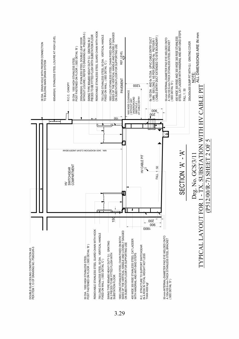
150
MIN. 3400 HEADROOM CLEAR UNDER BEAM
FALL
1 : 5
0
150
1800
1200
900200
200900
50 D
IA.
1000
HIG
H ST
AINL
ESS
STEE
LPO
ST F
ASTE
NED
ON
FLO
OR
( SE
E DE
TAIL
'B' )
REM
OVA
BLE
STAI
NLES
S ST
EEL
GUA
RD C
HAIN
WIT
H HO
OK
750
LONG
STA
INLE
SS S
TEEL
50
DIA.
VER
TICA
L HA
NDLE
FIXE
D O
N W
ALL
( SE
E DE
TAIL
'C' )
SWIN
G T
YPE
800x
800
HEAV
Y DU
TY G
.I. G
RATI
NGIN
2 P
IECE
S TO
BE
FITT
ED F
LUSH
WIT
HSU
BSTA
TIO
N FL
OO
R
HV SWIT
CHGE
ARCO
MPA
RTM
ENT
R.C.
C. C
ANO
PY
600x
600(
H) S
TAIN
LESS
STE
EL L
OUV
RE A
T HI
GH
LEVE
L
PAVE
MEN
T
1800
LO
NG S
TAIN
LESS
STE
EL C
HAIN
FIX
ED O
N BO
THSI
DES
OF
THE
VERT
ICAL
HAN
DLE
AND
LOO
SELY
SAG
GED
ON
SUBS
TATI
ON
FLO
OR
FOR
SUPP
ORT
ING
USE
750
LONG
STA
INLE
SS S
TEEL
50
DIA.
VER
TICA
L HA
NDLE
FIXE
D O
N W
ALL
( SE
E DE
TAIL
'C' )
38 D
IA.
DRAI
N HO
LE W
ITH
PRO
PER
CONN
ECTI
ON
TO B
UILD
ING
MAI
N DR
AIN
SYST
EM
HV C
ABLE
PIT
1600
WID
E CL
EARA
NCE
( WIT
HOUT
ANY
UND
ERG
ROUN
D O
BSTA
CLE
)AT
CAB
LE E
NTRY 6x 15
0 DIA
. AND
6x 75
DIA
. UPV
C CA
BLE
ENTR
Y DU
CT( M
IN. 5
00 LO
NG )
AS
PER
DRAW
ING
No. P
627/0
5/R-1
( CAB
LE E
NTRY
DUC
T EX
TEND
ED T
O SI
TE B
OUND
ARY
)
SWIN
G TY
PE 80
0x80
0 HEA
VY D
UTY
G.I.
GRAT
ING
IN 2
PIEC
ES T
O BE
FIT
TED
FLUS
H W
ITH
SUBS
TATI
ON F
LOOR
REM
OVA
BLE
STAI
NLES
S ST
EEL
GUA
RD C
HAIN
WIT
H HO
OK
50 D
IA.
1000
HIG
H ST
AINL
ESS
STEE
LPO
ST F
ASTE
NED
ON
FLO
OR
( SE
E DE
TAIL
'B' )
400 W
IDE
300 R
ISE
AND
300 W
IDE
300 R
ISE
STAI
NLES
SST
EEL C
AT LA
DDER
WIT
H HA
NDRA
IL AN
D AN
TI-S
KID
STEP
S
REF.
LEV
EL
SECT
ION
'A' -
'A'
R.C.
STR
UCTU
RE T
O S
UPPO
RT S
WIT
CHG
EAR
IN A
RO
W IN
TO
TAL
WEI
GHT
NO
T LE
SSTH
AN 4
000
kgf
400
WID
E 30
0 RI
SE S
TAIN
LESS
STE
EL C
AT L
ADDE
RW
ITH
HAND
RAIL
AND
ANT
I-SKI
D ST
EPS
1800
LO
NG S
TAIN
LESS
STE
EL C
HAIN
FIX
ED O
N BO
THSI
DES
OF
THE
VERT
ICAL
HAN
DLE
AND
LOO
SELY
SAG
GED
ON
SUBS
TATI
ON
FLO
OR
FOR
SUPP
ORT
ING
USE
50-m
m-IN
TERN
AL-D
IAM
ETER
PAD
EYE
WEL
DED
ONT
OA
100x
100
6-m
m-T
HICK
STA
INLE
SS S
TEEL
BRA
CKET
( SEE
DET
AIL
'D' )
50-m
m-IN
TERN
AL-D
IAM
ETER
PAD
EYE
WEL
DED
ONT
OA
100x
100
6-m
m-T
HICK
STA
INLE
SS S
TEEL
BRA
CKET
( SEE
DET
AIL
'D' )
300x
300x
300 S
UMP
PIT
WIT
H G.
I. GR
ATIN
G CO
VER
FALL
1 : 5
0
2000
x260
0(H)
STA
INLE
SS S
TEEL
DO
UBLE
LEA
F DO
OR
WIT
HOUT
LO
UVRE
( RE
FER
TO D
RAW
ING
No.
P59
2/03
/R-5
)
DOUB
LE-S
LAB
CEIL
ING
CO
NSTR
UCTI
ON
ASPE
R IT
EM 1
.13
OF
DRAW
ING
NO
. P58
5/03
/R-5
Drg
. No.
GC
S/3/
11TY
PIC
AL
LAY
OU
T FO
R 1
- TX
. SU
BST
ATI
ON
WIT
H H
V C
AB
LE P
IT(P
512/
00/R
-7) S
HEE
T 2
OF
5
NO
TE:
ALL
DIM
ENSI
ON
S AR
E IN
mm
3.29
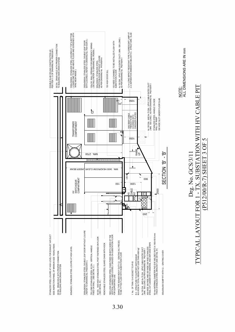
MIN. 3400 HEADROOM CLEAR UNDER BEAM
1050
1050
150
300150
MIN. 2700
300
400
1200
I R
200
2000
x260
0(H)
STA
INLE
SS S
TEEL
DO
UBLE
LEA
F DO
OR
WIT
H LO
UVRE
S ( R
EFER
TO
DRA
WIN
G N
o. P
591/
03/R
-5 )
600x
600(
H) S
TAIN
LESS
STE
EL L
OUV
RE A
T HI
GH
LEVE
L
400
WID
E 30
0 RI
SE A
ND 3
00 W
IDE
300
RISE
STA
INLE
SSST
EEL
CAT
LADD
ER W
ITH
HAND
RAIL
AND
ANT
I-SKI
D ST
EPS
6x 1
50 D
IA.
AND
6x 7
5 DI
A. U
PVC
CABL
E EN
TRY
DUCT
( MIN
. 50
0 LO
NG )
AS P
ER D
RAW
ING
No.
P62
7/05
/R-1
R.C.
STR
UCTU
RE T
O S
UPPO
RT S
WIT
CHG
EAR
IN A
RO
W IN
TO
TAL
WEI
GHT
NO
T LE
SS T
HAN
4000
kgf
1 N
o. O
F TW
IN 1
3-A
SOCK
ET T
O IP
65
SWIN
G T
YPE
800x
800
HEAV
Y DU
TY G
.I. G
RATI
NG IN
2 P
IECE
STO
BE
FITT
ED F
LUSH
WIT
H SU
BSTA
TIO
N FL
OO
R
1800
LO
NG S
TAIN
LESS
STE
EL C
HAIN
FIX
ED O
N BO
TH S
IDES
OF
THE
VERT
ICAL
HAN
DLE
AND
LOO
SELY
SAG
GED
ON
SUBS
TATI
ON
FLO
OR
FOR
SUPP
ORT
ING
USE
REM
OVA
BLE
STAI
NLES
S ST
EEL
GUA
RD C
HAIN
WIT
H HO
OK
50 D
IA.
1000
HIG
H ST
AINL
ESS
STEE
L PO
ST F
ASTE
NED
ON
FLO
OR
( SEE
DET
AIL
'B' )
HV SWIT
CHGE
ARCO
MPA
RTM
ENT
38 D
IA.
DRAI
N HO
LE W
ITH
PRO
PER
CONN
ECTI
ON
TO B
UILD
ING
MAI
N DR
AIN
SYST
EM
2000
x260
0(H)
STA
INLE
SS S
TEEL
DO
UBLE
LEA
F DO
OR
WIT
HOUT
LO
UVRE
( REF
ER T
O D
RAW
ING
No.
P59
2/03
/R-5
)
750
LONG
STA
INLE
SS S
TEEL
50
DIA.
VER
TICA
L HA
NDLE
FIXE
D O
N W
ALL
( SE
E DE
TAIL
'C' )
SIDE
INSP
ECTI
ON
PANE
L O
F M
INIM
UN S
IZE
150(
W)x
100(
H)
STAI
NLES
S ST
EEL
LOUV
RE A
T HI
GH
LEVE
L FO
R EX
HAUS
T AI
R DU
CTDO
UBLE
-SLA
B CE
ILIN
G C
ONS
TRUC
TIO
N AS
PER
ITEM
1.1
3 O
F DR
AWIN
G N
O. P
585/
03/R
-3
38 D
IA.
DRAI
N HO
LE W
ITH
PRO
PER
CONN
ECTI
ON
TO B
UILD
ING
MAI
N DR
AIN
SYST
EM
1000
x100
0(H)
STA
INLE
SS S
TEEL
LO
UVRE
S AT
TO
P &
BOTT
OM
( LO
WER
ONE
TO
BE
300
ABO
VE F
LOO
R AN
D SC
REEN
ED W
ITH
WIR
E M
ESH
INSI
DE )
130x
130
WAL
L O
PENI
NG F
OR
EMER
GEN
CY W
IRIN
G( D
ETAI
LS R
EFER
TO
DRA
WIN
G N
o. P
638/
06 )
150
HIG
H DO
OR
SILL
4x 1
50 D
IA.
UPVC
CAB
LE E
NTRY
DUC
T ( M
IN.
500
LONG
)AS
PER
DRA
WIN
G N
o. P
627/
05/R
-1
150
WID
E U-
CHAN
NEL
TO B
E IN
STAL
LED
FLUS
H W
ITH
SUBS
TATI
ON
FLO
OR
STAI
NLES
S ST
EEL
HAND
LE O
N SI
DEW
ALL
OF
RAM
P
6x 1
50 D
IA.
AND
6x 7
5 DI
A. U
PVC
CABL
E EN
TRY
DUCT
( MIN
. 50
0 LO
NG )
AS
PER
DRAW
ING
No.
P62
7/05
/R-1
SECT
ION
'B' -
'B'
920x
2300
(H)
STAI
NLES
S ST
EEL
PART
ITIO
N DO
OR
WIT
HOUT
LO
UVRE
AS P
ER D
RAW
ING
No.
P47
9/00
/R-6
TRAN
SFOR
MER
COM
PART
MEN
T
2500
900
300x
300x
300
SUM
P PI
T W
ITH
G.I.
GRA
TING
CO
VER
RAM
PUP
50-m
m-IN
TERN
AL-D
IAM
ETER
PAD
EYE
WEL
DED
ONT
O A
100
x100
6-m
m-T
HICK
STA
INLE
SS S
TEEL
BRA
CKET
(SEE
DET
AIL
'D')
I R1.
2-m
-LO
NG IM
PACT
RES
ISTA
NT T
YPE
FLUO
RESC
ENT
LAM
P AT
2-m
SEP
ARAT
ION
IMM
EDIA
TE B
ELO
W R
.C.
STRU
CTUR
E / S
LAB
HV CABL
EPI
T
1050
DEE
P CA
BLE
TREN
CH T
O B
ECO
VERE
D W
ITH
CHEQ
UER
PLAT
ES
500
WID
E SL
OT
UNDE
R FL
OO
R SL
AB
Drg
. No.
GC
S/3/
11TY
PIC
AL
LAY
OU
T FO
R 1
- TX
. SU
BST
ATI
ON
WIT
H H
V C
AB
LE P
IT(P
512/
00/R
-7) S
HEE
T 3
OF
5
NO
TE:
ALL
DIM
ENSI
ON
S AR
E IN
mm
3.30
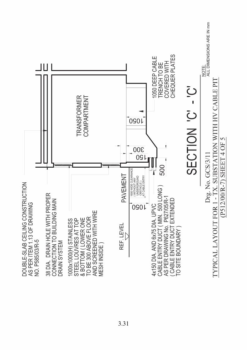
3.31

Drg
. No.
GC
S/3/
11TY
PIC
AL
LAY
OU
T FO
R 1
- TX
. SU
BST
ATI
ON
WIT
H H
V C
AB
LE P
IT(P
512/
00/R
-7) S
HEE
T 5
OF
5
NO
TE :
ALL
DIM
ENSI
ON
S AR
E IN
mm
3.32
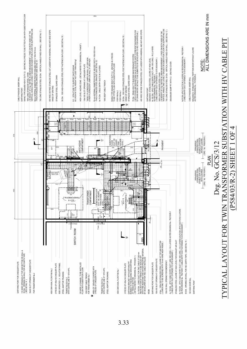
N B
Y R
H.V.
N B Y R
H.V.
TMC
T
TT
TT
TXT LVT
1050
DEE
P CA
BLE
TREN
CH
FOR
FAN
No.2
130x
130 W
ALL O
PENI
NG F
OR E
MERG
ENCY
MCBB
EART
HING
POI
NT F
OR C
HEQU
ER P
LATE
FOR
FAN
No.1
R.C.
C.
CANO
PY
FOR
TRAN
SFOR
MER
No.1
3 PIE
CES
OF 45
0x10
0 CHE
QUER
PLA
TE
4500
CMH
AXI
AL F
LOW
FAN
No.1
4500
CMH
AXI
AL F
LOW
FAN
No.2
STEE
L ADA
PTOR
TRU
NKIN
G
1050
DEE
P CA
BLE
TREN
CH
FOR
TRAN
SFOR
MER
No.2
SWIT
CH R
OOM
500
500
*
PLAN
1780
500
SIDE
OPE
RATE
D L.V
. ISO
LATO
R PA
NEL
50
500
50
STEE
L ADA
PTOR
TRU
NKIN
G
50
825
NOT LESS
710
1000
STAI
NLES
S ST
EEL L
OUVR
E AT
HIG
H LE
VEL F
OR E
XHAU
ST A
IR D
UCT
TXT
4450
3700
RTUOPT
BATT
CBMB
150 H
IGH
DOOR
SILL
600x
500(
H) S
TAIN
LESS
STE
EL LO
UVRE
AT
HIGH
LEVE
L
HING
E OF
GRA
TING
CBMB
CBMB
TMC
CBMB
PAVE
MENT
R.C.
C.
CANO
PY
300
50
300
50
800 150800150
900
700
300
300
T
50
55 D
IA. O
PENI
NG O
N W
ALL F
OR H
EC E
ARTH
TAP
E (
SEE
DETA
IL 'A
' )
CBMB CBMB CBMB CBMB
WB
400 W
IDE
300 R
ISE
STAI
NLES
S ST
EEL C
AT LA
DDER
WIT
H HA
NDRA
IL AN
D AN
TI-S
KID
STEP
S
7600
400 W
IDE
300 R
ISE
STAI
NLES
S ST
EEL C
AT LA
DDER
WIT
H HA
NDRA
IL AN
D AN
TI-S
KID
STEP
S
300x
300x
300 S
UMP
PIT
WIT
H G.
I. GR
ATIN
G CO
VER
55 D
IA. O
PENI
NG O
N W
ALL F
OR H
EC E
ARTH
TAP
E
HIGH
LEVE
L HAZ
ARD
ZONE
( D
ETAI
LS R
EFER
TO
DRAW
ING
No. P
346/9
7 )
1100
50x5
0 SLO
T OP
ENIN
G AT
CHE
QUER
PLA
TE
100x
100 S
LOT
OPEN
ING
AT C
HEQU
ER P
LATE
THAN 1000
450
440
200k
VAr
CAP.
BAN
K
750 L
ONG
STAI
NLES
S ST
EEL 5
0 DIA
. VER
TICA
L HAN
DLE
FIXE
D ON
WAL
L ( S
EE D
ETAI
L 'C'
)
50 D
IA. 1
000 H
IGH
STAI
NLES
S ST
EEL P
OST
FAST
ENED
ON
FLOO
R (
SEE
DETA
IL 'B
' )
STAI
NLES
S ST
EEL G
UARD
CHA
IN
50 D
IA. 1
000 H
IGH
STAI
NLES
S ST
EEL P
OST
FAST
ENED
ON
FLOO
R (
SEE
DETA
IL 'B
' )
STAI
NLES
S ST
EEL G
UARD
CHA
IN
750 L
ONG
STAI
NLES
S ST
EEL 5
0 DIA
. VER
TICA
L HAN
DLE
FIXE
D ON
WAL
L ( S
EE D
ETAI
L 'C'
)
SWIN
G TY
PE 80
0x80
0 HEA
VY D
UTY
G.I.
GRAT
ING
IN 2
PIEC
ES T
O BE
FIT
TED
FLUS
H W
ITH
SUBS
TATI
ON F
LOOR
HING
E OF
GRA
TING
300
450
300
1200
3 PIE
CES
OF 45
0x10
0 CHE
QUER
PLA
TE
700
50
2000
( CAB
LE E
NTRY
DUC
T EX
TEND
ED T
O SI
TE B
OUND
ARY
)
2500
500 1500500
HV SWIT
CHGE
ARCO
MPAR
TMEN
T
8x 15
0 DIA
. UPV
C CA
BLE
ENTR
Y DU
CT (
MIN.
500 L
ONG
) IN
2 LA
YERS
& 6x
75 D
IA U
PVC
DUCT
S IN
3 LA
YERS
AS P
ER D
RAW
ING
No. P
627/0
5/R-1
( CA
BLE
ENTR
Y DU
CT E
XTEN
DED
TO S
ITE
BOUN
DARY
)
4x 15
0 DIA
. UPV
C CA
BLE
ENTR
Y DU
CT (
MIN.
500 L
ONG
) IN
2 LA
YERS
AS
PER
DRAW
ING
No. P
627/0
5/R-1
TELBATTLV
'B'
'B'
'A''A'
115 W
IDE
OPEN
INGS
AT
TOP
AND
BOTT
OM O
N W
ALL &
( SEE
DET
AIL '
A' )
EART
HING
BRA
CKET
WIT
H EA
RTHI
NG P
ITBO
NDED
TO
THE
BUILD
ING
MAIN
EAR
THIN
GAT
TRE
NCH
BOTT
OM( D
ETAI
LS R
EFER
TO
DRAW
ING
No. P
574/0
2/R-1
)
( DRG
. No.
P59
1/03/R
-5 )
( DRG
. No.
P59
2/03/R
-5 )
100x
100
SLOT
OPE
NING
AT
CHEQ
UER
PLAT
E
EART
HING
POI
NT
EART
HING
POI
NT
EART
HING
POI
NT
1800
LONG
STA
INLE
SS S
TEEL
CHA
IN( I
N W
EIGH
T OF
3 kg
/ MET
RE IN
LINE
AR M
EASU
REME
NT )
FIX
ED O
N BO
TH S
IDES
OF
THE
VERT
ICAL
HAN
DLE
AND
LOOS
ELY
SAGG
ED O
N SU
BSTA
TION
FLO
OR F
OR S
UPPO
RTIN
G US
E
50-m
m-IN
TERN
AL-D
IAME
TER
PAD
EYE
WEL
DED
ONTO
A 10
0x10
0 6-m
m-T
HICK
STA
INLE
SS S
TEEL
BRA
CKET
(SEE
DET
AIL '
D')
THES
E 3 F
LUOR
ESCE
NT LA
MPS
ON W
ALL A
T 22
00 H
IGH
,OT
HER
FLUO
RESC
ENT
LAMP
S ON
WAL
L AT
2800
HIG
H
1800
LONG
STA
INLE
SS S
TEEL
CHA
IN( I
N W
EIGH
T OF
3 kg
/ MET
RE IN
LINE
AR M
EASU
REME
NT )
FIX
ED O
N BO
TH S
IDES
OF
THE
VERT
ICAL
HAN
DLE
AND
LOOS
ELY
SAGG
ED O
N SU
BSTA
TION
FLO
OR F
OR S
UPPO
RTIN
G US
E50
mm IN
TERN
AL D
IAME
TER
PAD
EYE
WEL
DED
ONTO
A 10
0x10
0 6-m
m-T
HICK
STA
INLE
SS S
TEEL
BRA
CKET
(SEE
DET
AIL '
D')
RAMP UP
( SUB
STAT
ION
FLO
OR IS
AT
150
HIG
HER
THA
N O
UTSI
DE LE
VEL )
'C'
'C'
TRANSFORMER No.2
TRAN
SFOR
MER
No.1
700
RAMP UP
DOW
N-ST
REAM
SILE
NCER
COMB
INED
L.V.
ISOL
ATOR
PAN
EL&
L.V. P
ANEL
ENCL
.B/
B
RAMP UP
8x 15
0 DIA
. UPV
C CA
BLE
ENTR
Y DU
CT (
MIN.
500 L
ONG
) IN
2 LA
YERS
AS P
ER D
RAW
ING
No. P
627/0
5/R-1
( CAB
LE E
NTRY
DUC
T EX
TEND
ED T
O SI
TE B
OUND
ARY
)
920x
2300
(H)
STAI
NLES
S ST
EEL P
ARTI
TION
DOO
R W
ITHO
UT LO
UVRE
AS P
ER D
RAW
ING
No. P
479/0
0/R-6
2000
x260
0(H)
STAI
NLES
S ST
EEL
DOUB
LE LE
AF D
OOR
WIT
H LO
UVRE
S
2000
x260
0(H)
STAI
NLES
S ST
EEL
DOUB
LE LE
AFDO
ORW
ITHO
UT LO
UVRE
6x75
DIA
UPV
C DU
CTS
IN 3
LAYE
RS A
S PE
R DR
AWIN
G No
. P62
7/05/R
-1( C
ABLE
ENT
RY D
UCT
EXTE
NDED
TO
SITE
BOU
NDAR
Y )
4 Nos
. 100
0x10
00 S
TAIN
LESS
STE
EL LO
UVRE
AT
TOP
AND
BOTT
OM( L
OWER
ONE
TO
BE S
CREE
NED
WIT
H 10
-mm
WIR
E ME
SH IN
SIDE
)
RAMP UP
CABL
E PA
SSAG
E UN
DER
WAL
L
6x 75
DIA
. CAB
LE E
NTRY
DUC
TS IN
3 LA
YERS
1650 1500
CABL
E PA
SSAG
E UN
DER
WAL
L
ENCL
.B/
B
TRAN
SIT
BLOC
K No
.2W
ITH
CENT
RE LI
NE A
T 15
70 A
FFL
1300
800
600 1350
VFC VFC
E N L3 L2 L1 E N L3 L2 L1
RAMPUP
SWIN
G TY
PE 80
0x80
0 HEA
VY D
UTY
G.I.
GRAT
ING
IN 2
PIEC
ESTO
BE
FITT
ED F
LUSH
WIT
H SU
BSTA
TION
FLO
OR
150 W
IDE
U-CH
ANNE
L TO
BE IN
STAL
LED
FLUS
H W
ITH
SUBS
TATI
ON F
LOOR
UPST
REAM
SILE
NCER
TRAN
SIT
BLOC
K No
.1W
ITH
CENT
RE LI
NE A
T 15
70 A
FFL
AREA
OF
1300
x500
COV
ERED
WIT
H3 P
IECE
S OF
CHE
QUER
PLA
TE
100
DOW
N-ST
REAM
SILE
NCER
UPST
REAM
SILE
NCER
2x 15
0 DIA
. CAB
LE D
UCT
FOR
TMC
CABL
E AT
200 m
mAB
OVE
BOTT
OM O
F TR
ENCH
TO
BE S
EALE
D OF
FW
ITH
FIRE
RES
ISTA
NT A
ND W
ATER
-PRO
OFIN
G MA
TERI
ALBY
DEV
ELOP
ER A
FTER
TMC
CAB
LE IN
STAL
LED
75 D
IA. D
RAIN
HOL
E TO
BUI
LDIN
G MA
IN D
RAIN
AGE
SYST
EM( W
ITH
COVE
R AN
D NO
N-RE
TURN
VAL
VE A
S FL
OOD
GATE
TO
PREV
ENT
BACK
WAR
D FL
OWOF
DRA
IN W
ATER
. DET
AILS
TO
BE S
UBMI
TTED
BY
DEVE
LOPE
R TO
HEC
FOR
APP
ROVA
L )
1000kg1000kg1000kg1000kg1000kg1000kg1000kg1000kg1000kg
R.C.
STR
UCTU
RE T
O SU
PPOR
T SW
ITCH
GEAR
IN A
ROW
IN T
OTAL
WEI
GHT
NOT
LESS
THA
N 90
00 kg
f
1710
( SUB
STAT
ION
FLOO
R IS
AT
150
HIGH
ER T
HAN
OUTS
IDE
LEVE
L )
TRAN
SFOR
MER
COMP
ARTM
ENT
EART
HING
POI
NT F
OR C
HEQU
ER P
LATE
500
800
Drg
. No.
GC
S/3/
12TY
PIC
AL
LAY
OU
T FO
R T
WIN
TR
AN
SFO
RM
ER S
UB
STA
TIO
N W
ITH
HV
CA
BLE
PIT
(P58
4/03
/R-2
) SH
EET
1 O
F 4
NO
TE:
ALL
DIM
ENSI
ON
S AR
E IN
mm
3.33
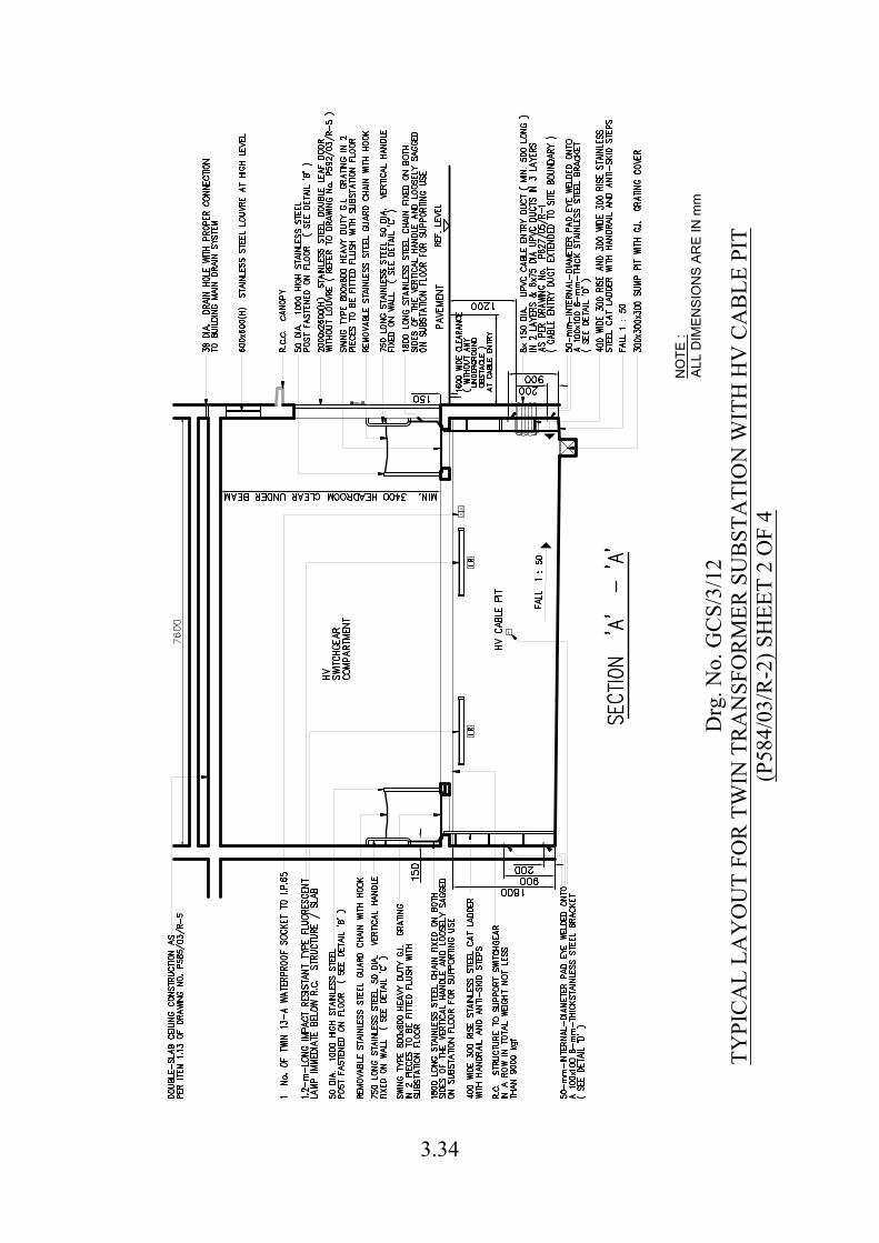
Drg
. No.
GC
S/3/
12TY
PIC
AL
LAY
OU
T FO
R T
WIN
TR
AN
SFO
RM
ER S
UB
STA
TIO
N W
ITH
HV
CA
BLE
PIT
(P58
4/03
/R-2
) SH
EET
2 O
F 4
NO
TE :
ALL
DIM
ENSI
ON
S AR
E IN
mm
3.34
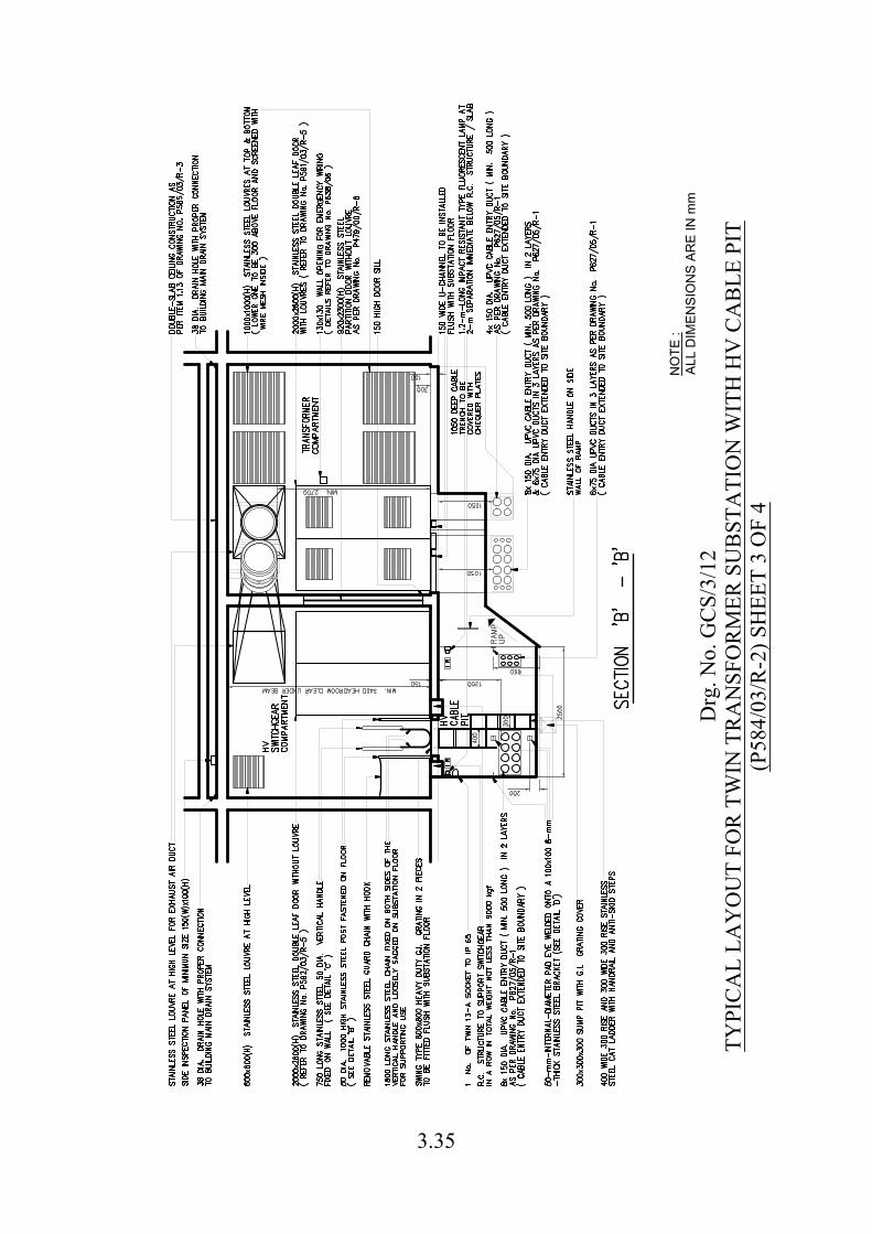
Drg
. No.
GC
S/3/
12TY
PIC
AL
LAY
OU
T FO
R T
WIN
TR
AN
SFO
RM
ER S
UB
STA
TIO
N W
ITH
HV
CA
BLE
PIT
(P58
4/03
/R-2
) SH
EET
3 O
F 4
NO
TE :
ALL
DIM
ENSI
ON
S AR
E IN
mm
3.35
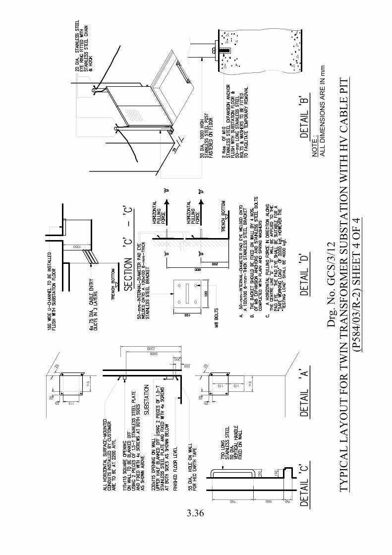
Drg
. No.
GC
S/3/
12TY
PIC
AL
LAY
OU
T FO
R T
WIN
TR
AN
SFO
RM
ER S
UB
STA
TIO
N W
ITH
HV
CA
BLE
PIT
(P58
4/03
/R-2
) SH
EET
4 O
F 4
NO
TE
:
AL
L D
IM
EN
SIO
NS
A
RE
IN
m
m
3.36
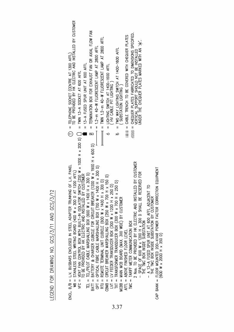
3.37
3.38
Notes for Drawing Nos. GCS/3/11, GCS/3/12 & GCS/3/30
DETAILED REQUIREMENTS OF SUBSTATION
1. BUILDER'S WORK 1.1 No construction joint nor expansion joint shall be constructed within a
substation and at the substation enclosure. 1.2 Unless otherwise specified in the substation layout drawing, the substation shall
have a clear headroom of 3400 mm. The substation floor shall be designed and constructed to withstand the weight of transformer, its associated HV switchgear and control equipment, each set of which is 10,000 kgf. The substation structure shall be designed to an average floor loading of not less than 20 kPa. Also all the floor area within the substation must be capable of withstanding a concentrated load of 100 kN over two Nos. of 40-mm x 600-mm rectangular strips which are the bottom channels of the above equipment. For those substations to be installed with HV switchgear only or those substations with a separate compartment solely for housing HV switchgear only, the substation floor designed to an average floor loading of not less than 10 kPa to withstand the weight of HV switchgear in such substations can be accepted. Before handing over the substation, the architect must submit detailed structural drawings, structure calculation and a certificate duly signed by a registered structural engineer, indicating that the substation structure has been designed and constructed to such requirements for HK Electric record.
1.3 The wall and ceiling of substation must be of construction including material and
thickness, etc., complying with regulations of Fire Services Department (FSD) and Building Department. The substation wall shall preferably be of reinforced concrete construction, but brick of clay to BS.3921, concrete brick to BS.6073 can also be accepted. Hollow blockwork in the substation will not be accepted.
1.4 The substation wall and ceiling shall be cemented, sand plastered and finished
with one coat of liquid prepolymer sealer and two finishing coats of acrylic resin based coating in gloss white finish. Substation floor shall be cemented, sand rendered in trowelled smooth finish. For anti-skid reasons, no coating nor painting shall be applied on the substation floor.
1.5 Non-slip strip inserts shall be installed at the edges of steps as specified in the
latest edition of “General Specification for Building” by Architectural Services Department (ASD) of Hong Kong SAR Government, at: i. staircase within the area to be locked up by HK Electric; and ii. staircase outside the area to be locked up by HK Electric, but forming part
of the route of escape for the substation.
3.39
Notes for Drawing Nos. GCS/3/11, GCS/3/12 & GCS/3/30 1.6 Substation wall and ceiling shall be finished to a true plane and to correct line
and level. Maximum deviation permitted in surfaces shall be 3 mm from a 1800-mm straight edge. Substation floor shall be finished to a true plane and to extremely correct line and level. Maximum deviation permitted in surfaces of substation floor shall be 2 mm from a 1800-mm straight edge. For steelwork, maximum deviation shall be 2 mm from a 1800-mm straight edge.
1.7 Unless otherwise specified by HK Electric, all the building work, structural work
and steelwork for the substation shall comply with the latest edition of "General Specification for Building" by ASD.
1.8 Unless otherwise specified by HK Electric, all exposed steelwork for substation
shall be hot dip galvanized to BS EN ISO 1461. 1.9 Unless otherwise specified, all trenches shall be covered with 7-mm-thick hot
dip galvanised steel chequer plates according to drawing No. P76/89/R-5. 1.10 Where removable precast concrete slabs are provided to cover preformed trench
after cable installation, each piece of concrete slab shall be provided with lifting eyes and shall not weigh above 80 kgf. The precast concrete slabs shall be numbered in a sequential order by painting numbers of 50 mm high in white colour on both surfaces of each precast concrete slab so as to facilitate reinstatement of precast concrete slabs after cables installed. A sketch in permanent manner showing the layout and numbering of precast concrete slabs shall be posted on the substation wall for reference. Where the slabs are along the route of transportation of substation equipment, the slabs shall be capable of withstanding an average loading of 20 kPa. Otherwise the slabs shall withstand 10 kPa. Certificate by a registered structural engineer shall be submitted.
1.11 Where G.I. gratings of heavy duty type are specified to cover cable trench or
cable pit, the G.I. gratings shall be fabricated with load bars of not less than 25 mm x 3 mm in cross-section, in grid size of approximately 30 mm x 100 mm and in weight of not less than 20 kgf/m2. The gratings shall withstand a uniformly distributed load of 4 kPa without any permanent deformation. It shall be ensured that the deflection across the span shall not exceed 4 mm when a test load of 16 kPa is uniformly applied. Details of load table and catalogue of the gratings shall be submitted by customer to HK Electric for record.
3.40
Notes for Drawing Nos. GCS/3/11, GCS/3/12 & GCS/3/30 1.12 The drain hole at substation floor or at cable chamber floor shall be connected to
the building main drainage system for discharging lodged water at substation trench and the position is shown in substation layout drawing. The drain shall be equipped with a non-return valve as a flood gate to prevent the backward flow of drain water into the substation. Such non-return valve should be operated by gravity flow only but not for pressurized application. Details of non-return valve and layout plan of drainage system connecting to the drain hole at substation floor shall be submitted by customer to HK Electric for record. A UPVC drain pipe of 75 mm diameter shall be provided with the drain hole for the discharge pipe of HK Electric’s portable pump. UPVC screw type cap shall be installed on the drain pipe to prevent odour / waste water overflow to the substation in case the floodgate fails. The drain hole shall be covered with a stainless steel lid of 3 mm thick, engraved “FLOOR DRAIN” about 8-mm letter high on external surface of the lid. The lid shall be fixed using 4 Nos. of 5-mm-diameter stainless steel screw with counter-sunk Philip screw head and air-tight gasket or O-ring. The lid and the fixing screws shall be flush with the finished floor surface.
1.13 SUBSTATION CEILING Except for the dedicated staircase/passage within the area locked up by HK Electric for personnel access and equipment transportation only but outside HV switchgear and transformer compartments, the entire substation ceiling shall be of double reinforced concrete slab construction. The following requirements shall be met for all types of substations:
a. The clear separation between the upper slab and the lower slab shall not be less than 100 mm. The thickness of lower slab shall not be less than 125 mm.
b. All finished surfaces of lower slab shall be smooth, firm and free of
voids, surface projections, loose materials, oil, grease and all foreign matter. No pipes, ducts, conduits nor services of any nature are to be embedded inside the lower slab.
c. No drain pipes shall be allowed to run inside the substation enclosure.
d. No timber left in formwork shall be allowed within the separation void.
e. The top surface of the lower slab shall be designed with gravity fall of 1:100 to avoid ponding of water. At least two drain holes with drain pipes of not less than 38 mm diameter shall be provided for the lower slab to discharge water to outside of the substation.
3.41
Notes for Drawing Nos. GCS/3/11, GCS/3/12 & GCS/3/30
f. A side inspection panel of minimum size of 150 mm wide by 100 mm high shall be provided to inspect the void between the upper and lower slabs. The side inspection panel shall be easily accessible from public area and be fitted with stainless steel label engraved“SUBSTATION DOUBLE-SLAB CEILING INSPECTION PANEL 電力分站雙層天 花板檢查面板”. The characters shall be in minimum 10 mm high in black colour. The side inspection panel shall be fixed using stainless steel screws.
g. In case the lower slab is divided into multi-compartment by ceiling
beams, each compartment shall have its own drain holes / drain pipes and side inspection panel.
h. A caution label of 300 mm by 200 mm shall be posted immediately
adjacent to each entrance of substation stating "DOUBLE-SLAB CEILING! NO DRILLING WORK!" and the Chinese translation 「雙 層天花板! 禁止鑽探!」. Same bilingual wording shall be stencil painted on the ceiling in red in character not less than 75 mm high at every 5m interval.
i. Unless otherwise specified in this Drawing, the lower and upper slabs
shall have waterproofing and water tightness conforming to the requirements regarding material and workmanship on “Roofing” as stipulated in the latest edition of General Specification for Building by ASD.
j. Drainage plan for lower and upper slabs, waterproofing details for
lower and upper slabs and waterproofing details for drain points serving lower and upper slabs shall be submitted. Cementitious type waterproofing for double slab will not be accepted.
Waterproofing material for upper and lower slab shall be materials of proprietary sheet or liquid membrane type roofing system. Proprietary roofing system shall be laid by specialist contractors. The asphalt / bituminous waterproof sheet membrane to ASTM standard, thickness not less than 3 mm and longitudinal elongation not less than 200% will be acceptable:- Other types of membrane, provided that technical details are submitted indicating equivalent waterproofing performance, will also be considered. Before commencing work, the contractor shall demonstrate on site that all adhesives and materials are fully compatible and shall be certified by the suppliers/manufacturers in writing.
3.42
Notes for Drawing Nos. GCS/3/11, GCS/3/12 & GCS/3/30
k. Waterproofing material shall be wrapped onto the inner face of water outlet or any case-in drains and drain pipes.
l. A copy of design drawing clearly indicating the locations of the
substation ceiling, drain holes, drain pipes, void area, vertical grating, side inspection panel etc. shall be submitted at early design stage.
m. An as-built drawing for substation ceiling shall be certified by an
Authorised Person (Cap.123) and be submitted to HK Electric at the time of substation inspection. The as-built drawing shall clearly indicate the locations of the drain holes, drain pipes, side inspection panel. A copy of the drawing shall be laminated and posted on substation wall for quick reference on site.
n. To ensure the effectiveness of waterproofing system for the double slab,
the following tests / inspections shall be carried out at the time of substation inspection and the details of results shall be certified by an Authorised Person and submitted to HK Electric: -
i. Flood test on lower slab with minimum 50-mm-depth water for at least 72 hours;
ii. Visual inspection on soffit of lower slab after the flood test;
iii. Flood test on upper slab with minimum 150-mm-depth water for at least 72 hours;
iv. CCTV inspection for soffit of upper slab through the Side Inspection Panel after the flood test; A DVD/VCD showing the CCTV inspection through the side inspection panel after the flood test shall be submitted to HK Electric for reference and record; and
v. The separation void shall be left clean and dry after the flood tests.
3.43
Notes for Drawing Nos. GCS/3/11, GCS/3/12 & GCS/3/30
2. CABLE ENTRY TO SUBSTATION 2.1 The architect is required to obtain information from utility companies and
conduct site survey (including trial trenches excavation) regarding the details of underground services and roadside trees in the vicinity of substation. The architect is to ensure early in the design stage that the cable entry points to the substation will not be obstructed by other underground services or located within the no-excavation zone of any roadside tree according to Register of Old and Valuable Trees of LCSD and code of practice published by authorities of HKSAR Government. Details of underground services and any roadside trees near cable entries shall be indicated on the Ground Floor Plan submitted to HK Electric.
2.2 Normally the width of cable trench to be excavated for commissioning a new
substation shall be taken as 1000 mm. The architect shall arrange excavation at the cable entry points within the site boundary for inspection by HK Electric engineer during hand-over of the substation. Where necessary the architect shall be responsible for clearing underground obstacles with other utility companies and any road side trees near cable entries before hand-over of substation.
2.3 Unless otherwise specified, all the cable entry point shall be at 1050 mm to
1300 mm below the pavement level outside the substation.
2.4 The cable entry of substation shall be properly sealed and watertight against ingress of water by the developer.
a. The last section of 4 m long (max) of 150-mm and 75-mm UPVC cable ducts will be provided by HK Electric. For cable ducts longer than 4m, the extra lengths of cable ducts are to be provided by the developer. Cable ducts of diameter other than 150 mm or 75 mm shall also be provided by developer.
b. The developer is required to collect UPVC ducts, duct spacers, sockets & end caps suitable for UPVC ducts or sleeves in nominal diameter of 150 mm and 75 mm provided and delivered to site by HK Electric. The developer is also required to install the cable ducts at site to ensure ducts or sleeves are constructed with correct spacing and level before concrete surroundings and application of sealings according to drawing No. P627/05/R-1.
c. All cable entry ducts or sleeves shall be capped by UPVC cap and sealed against water ingress or any noxious or explosive liquid or gas into the substation at the outside of substation before handing over the substation to HK Electric.

3.44
Notes for Drawing Nos. GCS/3/11, GCS/3/12 & GCS/3/30
d. The developer shall be responsible for re-sealing the occupied ducts or sleeves using cementitious mortar with waterproofing additive and/or expansible polyurethane foam or other waterproofing material at the ends outside substation of the ducts or sleeves after installation of cables by HK Electric. The thickness of sealant shall not exceed 75 mm so as to facilitate future removal of sealant inside the ducts when cables are installed by HK Electric. Fibre-glass cotton can be inserted inside the ducts to separate the sealants where necessary.
2.5 Where the substation entrance is via back lane, the architect shall be responsible
for aspects of flooding and illegal structure up to the point of public access which will obstruct the equipment transportation and cabling works by HK Electric. For preformed cable trench inside customer premises leading to the substation, suitable drains should be included to prevent lodgement of water inside the preformed trench. The preformed cable trench and draw pits (if any) shall be fully filled up with nylon sandbags by the builder after HK Electric’s cables have been installed.
2.6 Ducts or sleeves other than substation cable entry duct shall be of G.I. or UPVC
as specified. Where UPVC ducts or sleeves of nominal diameter 150 mm are specified, the material shall comply with BS 3506:1969, Class D and internal diameter shall be 146 mm +/-1 mm in order to suit the duct plugs used by HK Electric. Ducts of 200 mm diameter shall also comply with BS 3506:1969, Class D. If required, sockets shall be used to joint up duct lengths to ensure that the inside surface of ducts and sockets is smooth after being installed and assembled together.
3. SUBSTATION LIGHTING & POWER 3.1 The installation of substation lighting and power must comply with Electricity
Ordinance, Electricity (Wiring) Regulations and HK Electric’s Supply Rules. 3.2 Unless otherwise specified and except those wirings passing from customer's
switchroom to HK Electric substation, electrical wirings shall be enclosed in surface mounted G.I. conduit. Conductor size of wirings to be controlled by 5-A or 6-A MCB shall be of 1.5 mm² Cu and similarly 2.5 mm² Cu for 15-A or 16-A MCB; 6 mm² Cu for 30-A or 32-A MCB. Phase identification using L1, L2, L3 and N for 3-phase supply or L and N for 1-phase supply should be provided for all switches and final circuits. L1, L2, L3 label shall be attached to socket outlet and lighting switch to denote the supply phase.
3.3 The main MCB for substation lighting and power shall be of TP&N 4-pole
construction. All MCB used shall have a breaking capacity of not less than 9 kA. 3.4 A 32-A TP&N 4-pole 3-position selection switch supplied by HK Electric for
connection of supply to substation main MCB board shall be collected and installed by customer according to Drawing No. P561/01/R-7.

3.45
Notes for Drawing Nos. GCS/3/11, GCS/3/12 & GCS/3/30
3.5 Unless otherwise specified, fluorescent lamp on wall shall be at 2800 mm above
substation floor level. For substation with headroom over 3600 mm, the lamps below ceiling shall be supported such that the lamps are at 3200 mm above ground. Lighting in substation shall be fed by at least two final circuits of different phases. The layout of lamps shall be arranged in such a way that adjacent lamps are fed by different final circuits. The number of fluorescent tubes fed by each final circuit shall be approximately equal and no more than 8 per circuit.
3.6 Normal type fluorescent lamp fitting shall be installed unless Impact Resistant
Type Fluorescent Lamp Fitting is specified in the substation layout drawing. Impact Resistant Type Fluorescent Lamp Fitting will be marked "IR" next to the symbol in the drawing, and shall be installed in area of cable chamber, cable pit and cable shaft. The Impact Resistant Type Fluorescent Lamp Fitting shall comply with either (a) or (b) of the following requirements:
a. Diffuser of flame retardant material tested to withstand a mechanical
shock of not less than 10 Joules to EN60598 and stainless steel toggles as diffuser clips shall be fitted onto the lamp fitting.
b. A wire guard in approximately mesh size of 25 mm x 75 mm made from
stainless steel wire and not thinner than 3.25 mm diameter shall be fitted onto the lamp fitting or wall by stainless steel screws. The wire guard shall be of swing-down design and locked by wing-head nuts on both sides to facilitate replacement of fluorescent lamp.
3.7 Fluorescent lamp to be installed in HV cable pit shall be controlled by an
independent switch via an independent MCB, impact resistant type and fixed as close to the top of R.C. slabs or beams as practicable.
3.8 Emergency lighting, if so required by FSD, shall be backed up by emergency power supply from the building’s emergency generator, and according to FSD requirement. Each emergency light shall be labelled “EMERGENCY LIGHT” and the Chinese translation 「緊急照明」. Future maintenance / replacement of such emergency lighting and the associated fitting shall be the responsibilities of customer.
3.9 Socket outlets in substation shall be of 13 A in ring circuits and be provided with
L1, L2, L3 labels for phase identification in permanent manner. Socket outlets shall be installed at 600 mm above substation floor level unless otherwise specified. Socket outlets to be installed in HV cable pit shall be protected by an independent MCB, to IP65 standard and fixed as close to the top of R.C. slab or beam as practicable.
3.46
Notes for Drawing Nos. GCS/3/11, GCS/3/12 & GCS/3/30 3.10 Test on phase sequence, earth fault loop impedance, operating characteristics of
residue current device and 500-V megger test on the substation lighting and power installation shall be carried out and be witnessed by HK Electric engineer at the time of substation hand-over. Customer shall submit a copy of Work Completion Certificate (Government Form WR1) duly signed by a registered electrical worker for lighting & power installation in substation before substation handing over.
3.11 i. For staircase, passage, etc. within the area to be locked up by HK Electric,
where layout of fluorescent lamps is not specified by HK Electric, customer shall ensure that the lamps are installed so as to provide an illumination of not less than 150 lux measured at floor level.
ii. For staircase, passage, etc. outside the area to be locked up by HK Electric,
but forming part of the route of escape for the substation, illumination must be provided according to FSD requirement. Also the electricity supply to the lightings shall be from the essential board in the building.
3.12 Exposed metallic parts inside substation should be bonded to the substation
earthing connection in the manner laid down in Electricity (Wiring) Regulations. Brass or stainless steel bolts, nuts and washers shall be used at the equipotential bonding of exposed metallic parts for long lasting purpose.
3.13 Before energization of substation by HK Electric, the temporary wirings for
substation lighting and power shall be properly connected to the 5-pin male type socket of the 32-A T.P. & N. 4-pole 3-position selection switch via a female connector having corresponding rating and dimensions by customer for safety purpose.
4. CONDUITS IN SUBSTATION 4.1 Conduits, be they metallic or PVC, shall be supported and fixed to ceiling/side
wall at an interval of not more than 1200 mm. The method of anchoring conduits must be by red-head or similar device. Anchoring by raw plug or wood plug will not be accepted. No painting of G.I. conduit is required.
4.2 Unless otherwise specified, conduits shall not traverse low voltage busbar route
nor be running above HK Electric’s supply equipment marked on the substation drawing. All horizontal conduits of any purposes shall be installed at a level of 2200 mm above substation floor. Connection to cubicles / boxes mounted onto substation wall shall be by means of top entry vertical conduits dropped from the horizontal conduits. Where necessary to install conduits across substation door, the conduits shall be fitted above the door.
4.3 All electrical metallic conduits shall be continuous with good electrical joints at
boxes and couplings etc.
3.47
Notes for Drawing Nos. GCS/3/11, GCS/3/12 & GCS/3/30 4.4 For the purpose of installation of HK Electric’s trunking and earthing tapes, the
400 mm space on wall above substation floor should be free from any installation or conduit unless otherwise specified in this requirement.
5 VENTILATION SYSTEM IN SUBSTATION 5.1 Hangers for air duct shall be of U-shape, 40 mm x 7 mm thick hot dip galvanized
steel plate (or equivalent size) at interval of not more than 1200 mm. Hangers shall be provided on either side of air duct joint. The method of anchoring the hanger onto the ceiling/side wall must be by red-head or similar device. Anchoring by raw plug or wood plug will not be accepted. The air duct must be securely fixed to the hangers by means of hot dip galvanized steel or stainless steel bolts and nuts with washers.
5.2 The air duct shall be made of hot dip galvanized steel sheet of not less than
0.8 mm thick. No painting of the air duct is required. The headroom under the air duct shall be 2700 mm minimum, but not greater than 3200 mm. The air duct, fan and silencers shall not traverse low voltage busbar route nor be running above HK Electric’s supply equipment marked on the substation drawings.
5.3 Silencers, acoustic lining and/or acoustic plenum, etc. shall be installed to reduce
noise level to be not exceeding the values as stipulated in Noise Control Ordinance (NCO). In case of axial flow fans being provided by customer, the following must be submitted early at planning stage:
a. Drawings to show the configuration of the ventilation system. b. Drawings to show the locations of the existing or assumed nearest noise
sensitive receivers (NSR) and the corresponding distances away from the substation and supply/exhaust louvres.
c. Detailed acoustic calculation of the ventilation system to verify
compliance with the NCO, including tonality consideration, if any.
d. Description clearly indicating the approach and methodology on which the calculation is based.
e. A copy of the detailed references for the technical data adopted in the
calculation, including catalogues of ventilation fans and silencers, attenuation figures, etc.
If the acoustic calculation is not conclusive due to any reasons, a post-commissioning noise measurement at the identified NSR with entire 1/3 octave frequency spectrum from 31.5 Hz to 16 kHz has to be carried out by the developer to ensure compliance with the NCO.

3.48
Notes for Drawing Nos. GCS/3/11, GCS/3/12 & GCS/3/30
5.4 The noise level measured at any location within the substation and at 2 m above finished floor level of substation shall not exceed 85 dB(A) while all the intake/exhaust fans for the substation are in operation.
5.5 The as-measured noise level of ventilation system must not exceed the values
stipulated in Noise Control Ordinance. 5.6 Where two or more ventilation systems are installed, the ducting, fan, silencer,
control panel and other major parts shall be numbered in a permanent manner at intervals not exceeding 3 m.
5.7 Where intake fan system and exhaust fan system are installed, the ducting, fan,
silencer, control panel and other major parts shall be labelled "INTAKE 入風" and "EXHAUST 出風" accordingly and direction of air flow shall be indicated by using arrows in a permanent manner. Inter-tripping control box shall be provided for the intake and exhaust fans. The customer must demonstrate by calculation and on-site measurement that the INTAKE and EXHAUST paths will not be short-circuited.
5.8 Unless otherwise specified by HK Electric, the air duct shall be so designed that
the average air velocity at any cross-section shall not exceed 4.2 m/s.
5.9 For substations to be equipped with exhaust fan only, the average air velocity at exhaust louvres shall not exceed 3.0 m/s. Also the inclined angle at the gradual expansion of exhaust louvres shall not be more than 30°.
5.10 For substations to be equipped with intake/exhaust fans, the average air velocity
at intake/exhaust louvres shall not exceed 3.0 m/s. Also the inclined angle at the gradual expansion of intake/exhaust louvres shall not be more than 30°.
5.11 For remote on/off control of substation ventilation system, customer is required
to install fan control box(es) which will be supplied by HK Electric in the substation according to HK Electric drawing No. P382/98/R-2 before handing over the substation. A pair of dry contact (220 V, 5 A) shall be provided to HK Electric for controlling the ventilation fan if central control system is used by customer where control box provided by HK Electric is not applicable. Such details of electrical control system shall be submitted to HK Electric for approval at design stage.
5.12 Local emergency switch shall be provided at a level not exceeding 500 mm
above the bottom of fan and within 1 metre from each ventilation fan. The switch may be installed on wall, ceiling or an independent steel framework, but shall be installed as close as possible to the ventilation fan junction box and must not be fixed onto the axial flow fan or silencers.
6. VENTILATION LOUVRES ON SUBSTATION WALL 6.1 Ventilation louvres shall be provided on substation walls as specified in HK
Electric drawings. The constructional details are shown on drawing No. P638/06.
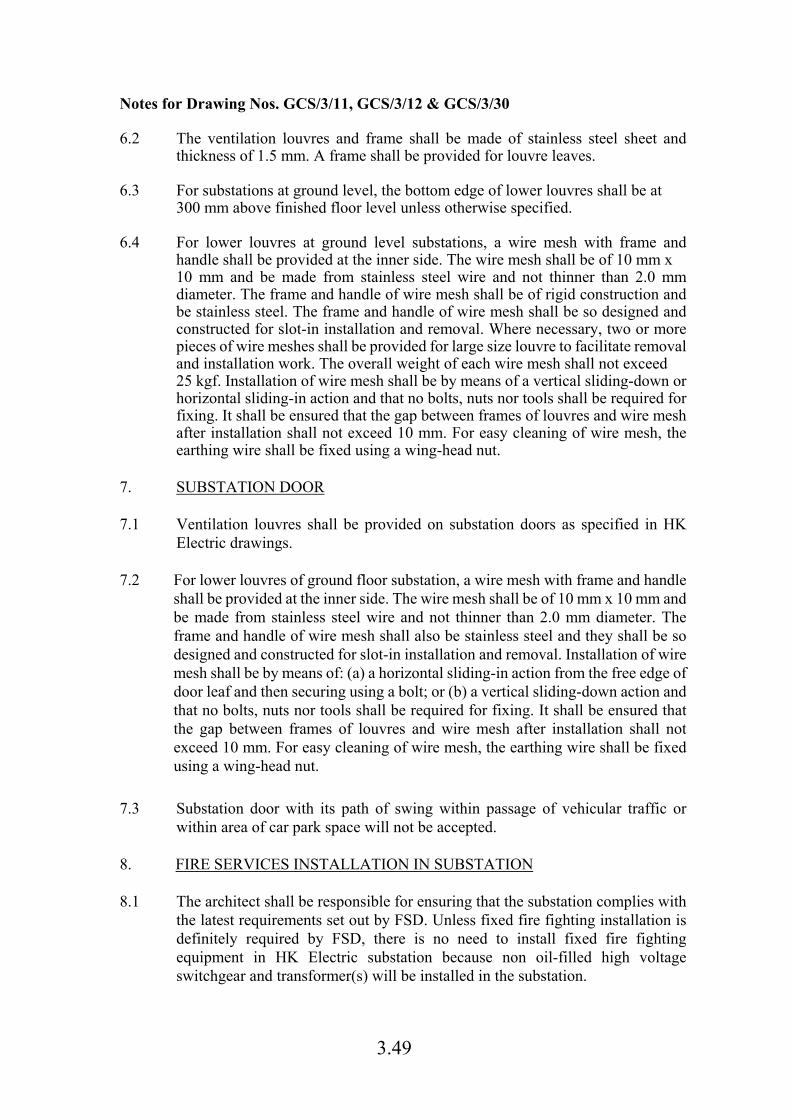
3.49
Notes for Drawing Nos. GCS/3/11, GCS/3/12 & GCS/3/30 6.2 The ventilation louvres and frame shall be made of stainless steel sheet and
thickness of 1.5 mm. A frame shall be provided for louvre leaves. 6.3 For substations at ground level, the bottom edge of lower louvres shall be at
300 mm above finished floor level unless otherwise specified. 6.4 For lower louvres at ground level substations, a wire mesh with frame and
handle shall be provided at the inner side. The wire mesh shall be of 10 mm x 10 mm and be made from stainless steel wire and not thinner than 2.0 mm diameter. The frame and handle of wire mesh shall be of rigid construction and be stainless steel. The frame and handle of wire mesh shall be so designed and constructed for slot-in installation and removal. Where necessary, two or more pieces of wire meshes shall be provided for large size louvre to facilitate removal and installation work. The overall weight of each wire mesh shall not exceed 25 kgf. Installation of wire mesh shall be by means of a vertical sliding-down or horizontal sliding-in action and that no bolts, nuts nor tools shall be required for fixing. It shall be ensured that the gap between frames of louvres and wire mesh after installation shall not exceed 10 mm. For easy cleaning of wire mesh, the earthing wire shall be fixed using a wing-head nut.
7. SUBSTATION DOOR 7.1 Ventilation louvres shall be provided on substation doors as specified in HK
Electric drawings. 7.2 For lower louvres of ground floor substation, a wire mesh with frame and handle
shall be provided at the inner side. The wire mesh shall be of 10 mm x 10 mm and be made from stainless steel wire and not thinner than 2.0 mm diameter. The frame and handle of wire mesh shall also be stainless steel and they shall be so designed and constructed for slot-in installation and removal. Installation of wire mesh shall be by means of: (a) a horizontal sliding-in action from the free edge of door leaf and then securing using a bolt; or (b) a vertical sliding-down action and that no bolts, nuts nor tools shall be required for fixing. It shall be ensured that the gap between frames of louvres and wire mesh after installation shall not exceed 10 mm. For easy cleaning of wire mesh, the earthing wire shall be fixed using a wing-head nut.
7.3 Substation door with its path of swing within passage of vehicular traffic or
within area of car park space will not be accepted. 8. FIRE SERVICES INSTALLATION IN SUBSTATION 8.1 The architect shall be responsible for ensuring that the substation complies with
the latest requirements set out by FSD. Unless fixed fire fighting installation is definitely required by FSD, there is no need to install fixed fire fighting equipment in HK Electric substation because non oil-filled high voltage switchgear and transformer(s) will be installed in the substation.
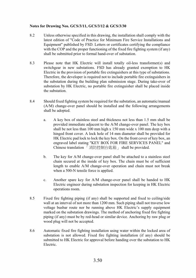
3.50
Notes for Drawing Nos. GCS/3/11, GCS/3/12 & GCS/3/30 8.2 Unless otherwise specified in this drawing, the installation shall comply with the
latest edition of "Code of Practice for Minimum Fire Service Installations and Equipment" published by FSD. Letters or certificates certifying the compliance with the COP and the proper functioning of the fixed fire fighting system (if any) shall be submitted prior to formal hand-over of substation.
8.3 Please note that HK Electric will install totally oil-less transformer(s) and switchgear in new substations. FSD has already granted exemption to HK Electric in the provision of portable fire extinguishers at this type of substations. Therefore, the developer is required not to include portable fire extinguishers in the substation during the building plan submission stage. During take-over of substation by HK Electric, no portable fire extinguisher shall be placed inside the substation.
8.4 Should fixed fighting system be required for the substation, an automatic/manual
(A/M) change-over panel should be installed and the following arrangements shall be adopted.
a. A key box of stainless steel and thickness not less than 1.5 mm shall be
provided immediate adjacent to the A/M change-over panel. The key box shall be not less than 100 mm high x 150 mm wide x 100 mm deep with a hinged front cover. A lock hole of 14 mm diameter shall be provided for HK Electric pad lock to lock the key box. On the front cover of key box, an engraved label stating "KEY BOX FOR FIRE SERVICES PANEL" and Chinese translation 「消防控制台匙箱」 shall be provided.
b. The key for A/M change-over panel shall be attached to a stainless steel
chain secured at the inside of key box. The chain must be of sufficient length to enable A/M change-over operation and chain must not break when a 500-N tensile force is applied.
c. Another spare key for A/M change-over panel shall be handed to HK
Electric engineer during substation inspection for keeping in HK Electric operations room.
8.5 Fixed fire fighting piping (if any) shall be supported and fixed to ceiling/side
wall at an interval of not more than 1200 mm. Such piping shall not traverse low voltage busbar route nor be running above HK Electric’s supply equipment marked on the substation drawings. The method of anchoring fixed fire fighting piping (if any) must be by red-head or similar device. Anchoring by raw plug or wood plug will not be accepted.
8.6 Automatic fixed fire fighting installation using water within the locked area of substation is not allowed. Fixed fire fighting installation (if any) should be submitted to HK Electric for approval before handing over the substation to HK Electric.
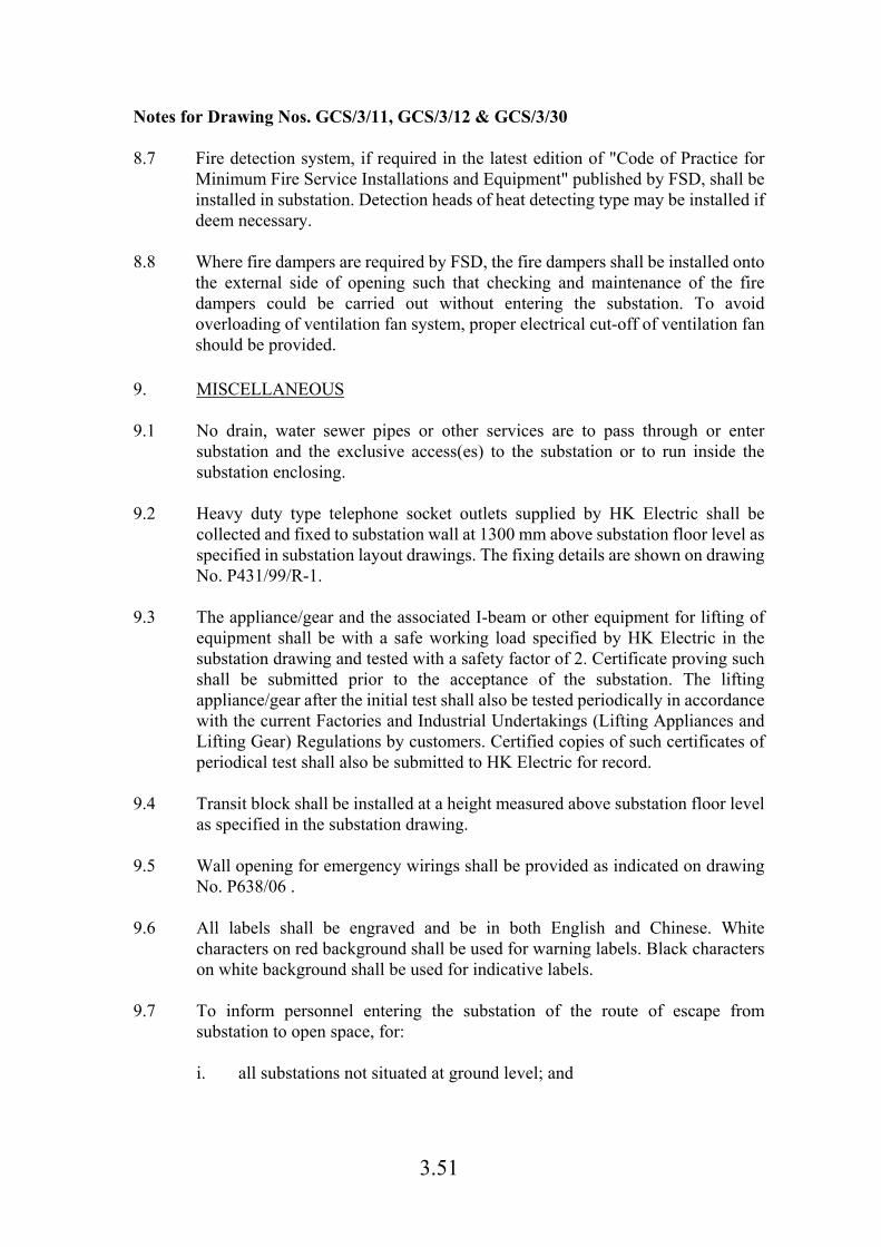
3.51
Notes for Drawing Nos. GCS/3/11, GCS/3/12 & GCS/3/30 8.7 Fire detection system, if required in the latest edition of "Code of Practice for
Minimum Fire Service Installations and Equipment" published by FSD, shall be installed in substation. Detection heads of heat detecting type may be installed if deem necessary.
8.8 Where fire dampers are required by FSD, the fire dampers shall be installed onto
the external side of opening such that checking and maintenance of the fire dampers could be carried out without entering the substation. To avoid overloading of ventilation fan system, proper electrical cut-off of ventilation fan should be provided.
9. MISCELLANEOUS 9.1 No drain, water sewer pipes or other services are to pass through or enter
substation and the exclusive access(es) to the substation or to run inside the substation enclosing.
9.2 Heavy duty type telephone socket outlets supplied by HK Electric shall be
collected and fixed to substation wall at 1300 mm above substation floor level as specified in substation layout drawings. The fixing details are shown on drawing No. P431/99/R-1.
9.3 The appliance/gear and the associated I-beam or other equipment for lifting of
equipment shall be with a safe working load specified by HK Electric in the substation drawing and tested with a safety factor of 2. Certificate proving such shall be submitted prior to the acceptance of the substation. The lifting appliance/gear after the initial test shall also be tested periodically in accordance with the current Factories and Industrial Undertakings (Lifting Appliances and Lifting Gear) Regulations by customers. Certified copies of such certificates of periodical test shall also be submitted to HK Electric for record.
9.4 Transit block shall be installed at a height measured above substation floor level
as specified in the substation drawing.
9.5 Wall opening for emergency wirings shall be provided as indicated on drawing No. P638/06 .
9.6 All labels shall be engraved and be in both English and Chinese. White
characters on red background shall be used for warning labels. Black characters on white background shall be used for indicative labels.
9.7 To inform personnel entering the substation of the route of escape from
substation to open space, for:
i. all substations not situated at ground level; and
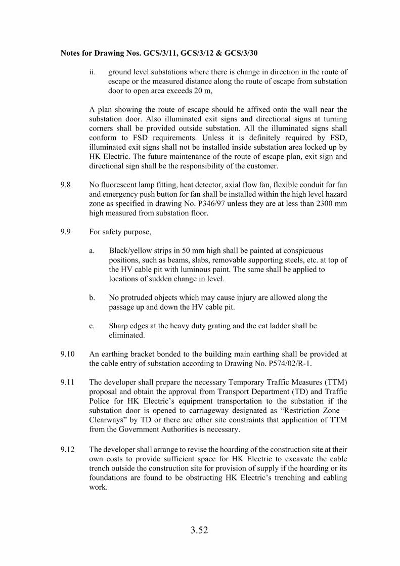
3.52
Notes for Drawing Nos. GCS/3/11, GCS/3/12 & GCS/3/30
ii. ground level substations where there is change in direction in the route of escape or the measured distance along the route of escape from substation door to open area exceeds 20 m,
A plan showing the route of escape should be affixed onto the wall near the substation door. Also illuminated exit signs and directional signs at turning corners shall be provided outside substation. All the illuminated signs shall conform to FSD requirements. Unless it is definitely required by FSD, illuminated exit signs shall not be installed inside substation area locked up by HK Electric. The future maintenance of the route of escape plan, exit sign and directional sign shall be the responsibility of the customer.
9.8 No fluorescent lamp fitting, heat detector, axial flow fan, flexible conduit for fan
and emergency push button for fan shall be installed within the high level hazard zone as specified in drawing No. P346/97 unless they are at less than 2300 mm high measured from substation floor.
9.9 For safety purpose,
a. Black/yellow strips in 50 mm high shall be painted at conspicuous
positions, such as beams, slabs, removable supporting steels, etc. at top of the HV cable pit with luminous paint. The same shall be applied to locations of sudden change in level.
b. No protruded objects which may cause injury are allowed along the
passage up and down the HV cable pit.
c. Sharp edges at the heavy duty grating and the cat ladder shall be eliminated.
9.10 An earthing bracket bonded to the building main earthing shall be provided at
the cable entry of substation according to Drawing No. P574/02/R-1.
9.11 The developer shall prepare the necessary Temporary Traffic Measures (TTM) proposal and obtain the approval from Transport Department (TD) and Traffic Police for HK Electric’s equipment transportation to the substation if the substation door is opened to carriageway designated as “Restriction Zone – Clearways” by TD or there are other site constraints that application of TTM from the Government Authorities is necessary.
9.12 The developer shall arrange to revise the hoarding of the construction site at their
own costs to provide sufficient space for HK Electric to excavate the cable trench outside the construction site for provision of supply if the hoarding or its foundations are found to be obstructing HK Electric’s trenching and cabling work.

3.53
Notes for Drawing Nos. GCS/3/11, GCS/3/12 & GCS/3/30
9.13 Stainless steel shall mean stainless steel of grade 316 unless otherwise specified.
9.14 The customers in the development shall ensure that the substation equipment
transportation route within the customer’s premises is properly maintained and cleared from obstruction at all times. The facilities (including lifting appliances, lifting gear, freight lifts, etc.) provided by the developer for the purpose of transportation of equipment shall be properly maintained by the customers in the building at their own costs to satisfy the legal requirements.
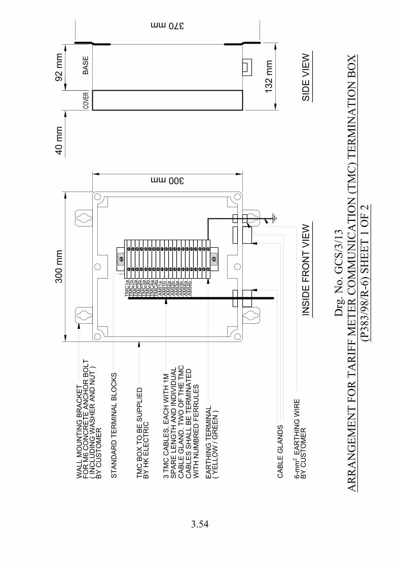
TM
C1a
TM
C1b
TM
C2a
TM
C2b
TM
C3a
TM
C3b
TM
C4a
TM
C4b
AM
I1b
AM
I1a
AM
I2a
AM
I2b
AM
I3a
AM
I3b
AM
I4a
AM
I4b
ST
AN
DA
RD
T
ER
MIN
AL B
LO
CK
S
WA
LL M
OU
NT
IN
G B
RA
CK
ET
FO
R M
6 C
ON
CR
ET
E A
NC
HO
R B
OLT
( IN
CLU
DIN
G W
AS
HE
R A
ND
N
UT
)
BY
C
US
TO
ME
R
TM
C B
OX
T
O B
E S
UP
PLIE
D
BY
H
K E
LE
CT
RIC
EA
RT
HIN
G T
ER
MIN
AL
( Y
ELLO
W / G
RE
EN
)
CA
BLE
G
LA
ND
S
2
CO
VE
RB
AS
E
300 m
m
300 mm
40 m
m
370 mm
132 m
m
6-m
m E
AR
TH
IN
G W
IR
E
BY
C
US
TO
ME
R
3 T
MC
C
AB
LE
S, E
AC
H W
IT
H 1M
SP
AR
E LE
NG
TH
A
ND
IN
DIV
ID
UA
L
CA
BLE
G
LA
ND
. T
WO
O
F T
HE
T
MC
CA
BLE
S S
HA
LL B
E T
ER
MIN
AT
ED
WIT
H N
UM
BR
ED
F
ER
RU
LE
S
IN
SID
E F
RO
NT
V
IE
WS
ID
E V
IE
W
92 m
m
Drg
. No.
GC
S/3/
13A
RR
AN
GEM
ENT
FOR
TA
RIF
F M
ETER
CO
MM
UN
ICA
TIO
N (T
MC
) TER
MIN
ATI
ON
BO
X(P
383/
98/R
-6) S
HEE
T 1
OF
2
3.54
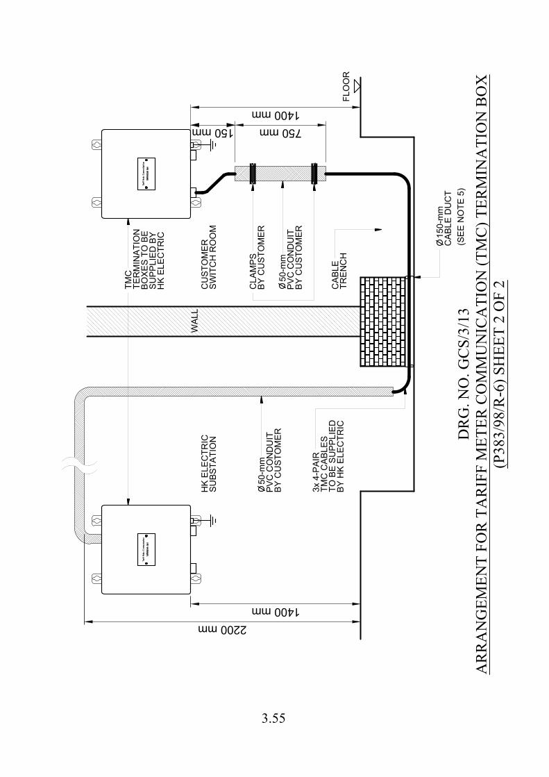
HK
E
LE
CT
RIC
SU
BS
TA
TIO
N
CA
BLE
TR
EN
CH
CLA
MP
S
BY
C
US
TO
ME
R
TM
C
TE
RM
IN
AT
IO
N
BO
XE
S T
O B
E
SU
PP
LIE
D B
Y
HK
E
LE
CT
RIC
CU
ST
OM
ER
SW
IT
CH
R
OO
M
FLO
OR
(S
EE
N
OT
E 5)
750 mm
1400 mm
150 mm
2200 mm
1400 mm
WA
LL
50-m
m
PV
C C
ON
DU
IT
BY
C
US
TO
ME
R
50-m
m
PV
C C
ON
DU
IT
BY
C
US
TO
ME
R
150-m
m
CA
BLE
D
UC
T
3x 4-P
AIR
TM
C C
AB
LE
S
TO
B
E S
UP
PLIE
D
BY
H
K E
LE
CT
RIC
DR
G. N
O. G
CS/
3/13
AR
RA
NG
EMEN
T FO
R T
AR
IFF
MET
ER C
OM
MU
NIC
ATI
ON
(TM
C) T
ERM
INA
TIO
N B
OX
(P38
3/98
/R-6
) SH
EET
2 O
F 2
3.55
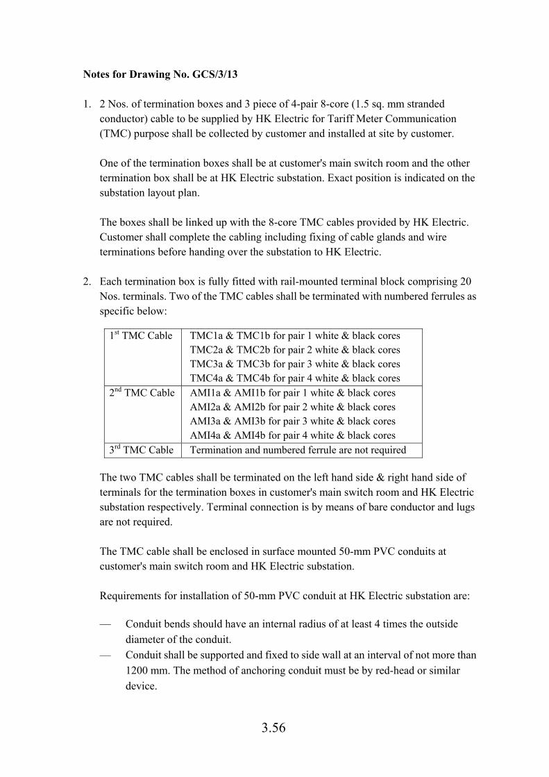
3.56
Notes for Drawing No. GCS/3/13 1. 2 Nos. of termination boxes and 3 piece of 4-pair 8-core (1.5 sq. mm stranded
conductor) cable to be supplied by HK Electric for Tariff Meter Communication (TMC) purpose shall be collected by customer and installed at site by customer. One of the termination boxes shall be at customer's main switch room and the other termination box shall be at HK Electric substation. Exact position is indicated on the substation layout plan. The boxes shall be linked up with the 8-core TMC cables provided by HK Electric. Customer shall complete the cabling including fixing of cable glands and wire terminations before handing over the substation to HK Electric.
2. Each termination box is fully fitted with rail-mounted terminal block comprising 20 Nos. terminals. Two of the TMC cables shall be terminated with numbered ferrules as specific below:
1st TMC Cable TMC1a & TMC1b for pair 1 white & black cores TMC2a & TMC2b for pair 2 white & black cores TMC3a & TMC3b for pair 3 white & black cores TMC4a & TMC4b for pair 4 white & black cores
2nd TMC Cable AMI1a & AMI1b for pair 1 white & black cores AMI2a & AMI2b for pair 2 white & black cores AMI3a & AMI3b for pair 3 white & black cores AMI4a & AMI4b for pair 4 white & black cores
3rd TMC Cable Termination and numbered ferrule are not required
The two TMC cables shall be terminated on the left hand side & right hand side of terminals for the termination boxes in customer's main switch room and HK Electric substation respectively. Terminal connection is by means of bare conductor and lugs are not required. The TMC cable shall be enclosed in surface mounted 50-mm PVC conduits at customer's main switch room and HK Electric substation. Requirements for installation of 50-mm PVC conduit at HK Electric substation are: — Conduit bends should have an internal radius of at least 4 times the outside
diameter of the conduit.
— Conduit shall be supported and fixed to side wall at an interval of not more than
1200 mm. The method of anchoring conduit must be by red-head or similar
device.
3.57
Notes for Drawing No. GCS/3/13 — Adaptable boxes should be provided immediately after every two bends, or after
a bend plus a total maximum straight run of 10 metres or after a maximum
straight run of 15 metres.
— The method of carrying out the conduit bends, fixing conduits to boxes, and the
tools and materials to be used should be as recommended by the manufacturer
of the conduit.
3. Each termination box is fitted with a yellow/green earthing terminal at the end of the terminal block. A 6-sq. mm earthing wire shall be provided and terminated by the customer to the corresponding substation/switch room electrical conduit system.
4. Each box shall be mounted on wall of substation/switch room at 1400 mm above finished floor level.
5. The 150-mm-diameter cable duct shall be properly sealed off with fire resistant material and water-proofed against ingress of water by customer after TMC cable installed.
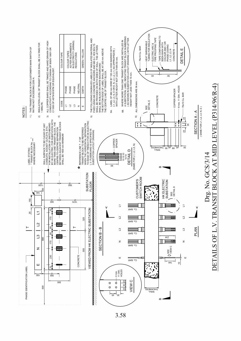
144
10
300
3045
90
234
40
500
555
100
100 500
25
L1L2
L3N
E
L1L2
L3N
E
PLAN
SEC
TIO
N B
- B
Cu. BAR
Cu. BAR
Cu. BAR
Cu. BAR
Cu. BAR
SEE
VIEW
CSE
ED
ETAI
L D
THICKNESSWALL
CU
STO
MER
'SSW
ITC
H R
OO
M
HK
ELEC
TRIC
SUBS
TATI
ON
BB
A
300 1570
SUBS
TATI
ON
FLO
OR
CO
NC
RET
E
LABE
L ST
ATIN
G" T
RAN
SIT
BLO
CK
No.
"
WH
ERE
NEC
ESSA
RY
SEC
TIO
N A
- A
THICKNESSWALL
50 40 69 45 30
30
2323
76x1
0 C
u. B
AR
CO
NC
RET
E
THIS
TR
ANSI
T BL
OC
K IS
FO
R C
UST
OM
ER'S
MAI
N S
WIT
CH
OF
RAT
ING
NO
T EX
CEE
DIN
G 2
250
A.
INSU
LATI
ON
LEV
EL O
F TR
ANSI
T BL
OC
K SH
ALL
BE 3
kV
RM
S FO
R
1 M
INU
TE.
1 )
2) 3) 4)
L1 L2 L3 N E
NEU
TRAL
EAR
THG
REE
N /
YELL
OW
CO
LOU
R T
APE
NO
TES
: 8 no
s. 1
1 D
IA. H
OLE
S
4 no
s.11
DIA
.H
OLE
S23
3023
VIEW
CD
ETAI
L D
1010
1010
10
CO
PPER
SPAC
ER
CO
NC
RET
E
ELEC
TRIC
AR
C &
FIR
E PR
OO
FIN
G T
APE
CO
PPER
SPA
CER
DET
AIL
E
SEE
DET
AIL
E
76x1
0 C
u. B
AR
HEA
T SH
RIN
KABL
ETU
BIN
G F
OR
INSU
LATI
ON
150
9001100
WAL
L SU
RFA
CE
TO B
E C
LEAR
OF
ANY
CO
ND
UIT
S, S
OC
KET
OU
TLET
S, E
TC.
FOR
INST
ALLA
TIO
N O
F SW
ITC
HBO
ARD
BY H
K EL
ECTR
IC. F
OR
SU
BSTA
TIO
N W
ITH
MO
RE
THAN
ON
E TR
ANSI
T BL
OC
K, T
HE
CEN
TRE-
TO-C
ENTR
E SE
PAR
ATIO
NBE
TWEE
N A
DJA
CEN
T TR
ANSI
T BL
OC
KSSH
ALL
BE 1
600
mm
MIN
IMU
M
7017
017
023
070
T TR
EFER
ENC
E LI
NE
T - T
OF
TRAN
SIT
BLO
CK
TO B
E R
EFER
RED
WH
EN T
HE
HO
RIZ
ON
TAL
SEPA
RAT
ION
TO E
DG
E O
F TR
ENC
H F
OR
HK
ELEC
TRIC
L.V.
FU
SEBO
ARD
IS S
PEC
IFIE
D IN
SUBS
TATI
ON
LAY
OU
T D
RAW
ING
* (SAM
E FO
R L
1, L
2, L
3, N
)
( SAM
E FO
R L
1, L
2, L
3, N
, E )
PHAS
E
PHAS
E
PHAS
E
CO
LOU
R T
APES
AS P
ER R
EQU
IRM
ENTS
IN E
LEC
TRIC
ITY
(WIR
ING
)R
EGU
LATI
ON
S
CO
DE
EN
L3L2
L188
0
300
VIEW
ED F
RO
M H
K EL
ECTR
IC S
UBS
TATI
ON
5A.
5B.
LABE
L O
F 88
0 m
m W
IDE
BY 1
00 m
m H
IGH
MAR
KED
WIT
H
5)TH
E FO
LLO
WIN
G E
NG
RAV
ED L
ABEL
S O
F IN
SULA
TED
MAT
ERIA
L AN
D
SHAL
L BE
PR
OVI
DED
ON
BO
TH S
IDES
OF
WAL
L. T
HE
LETT
ERS
SHAL
L BE
IN B
LAC
K O
N W
HIT
E BA
CKG
RO
UN
D.
THE
BOTT
OM
ED
GE
OF
LABE
L SH
ALL
BE A
T 30
0 m
m A
BOVE
THE
CEN
TRE
LIN
E O
F TR
ANSI
T BL
OC
K.
L1, L
2, L
3, N
, E O
R E
, N, L
3, L
2, L
1 ( A
S AP
PRO
PRIA
TE )
WIT
H L
ETTE
R H
EIG
HT
NO
T LE
SS T
HAN
50
mm
.
( AS
SHO
WN
IN S
UBS
TATI
ON
LAY
OU
T D
RAW
ING
) W
ITH
LET
TER
H
EIG
HT
NO
T LE
SS T
HAN
15
mm
.
WH
ERE
MO
RE
THAN
ON
E TR
ANSI
T BL
OC
K AR
E IN
STAL
LED
INA
SUBS
TATI
ON
, LAB
EL IN
DIC
ATIN
G T
RAN
SIT
BLO
CK
NU
MBE
RIN
G
8585
ALL
CO
PPER
BAR
S SH
ALL
BE T
INN
ED A
ND
HAR
D D
RAW
N O
F H
IGH
CO
ND
UC
TIVI
TY A
CC
OR
DIN
G T
O C
W00
4A O
F BS
EN 1
3601
OR
C11
000
OF
ASTM
B18
7M O
R E
QU
IVAL
ENT.
FIXE
D U
SIN
G M
6 C
ON
CR
ETE
ANC
HO
RS
AND
M6
G.I.
HEX
BO
LTS
TAPE
CO
NFO
RM
ING
TO
BSEN
604
54 W
ITH
CO
LOU
R A
ND
/ O
RPH
ASE
CO
DIN
GL1
, L2,
L3,
N
PHAS
E ID
ENTI
FIC
ATIO
N L
ABEL
50
325
6)AL
L D
IMEN
SIO
NS
ARE
IN m
m.
Drg
. No.
GC
S/3/
14D
ETA
ILS
OF
L.V
. TR
AN
SIT
BLO
CK
AT
MID
LEV
EL (P
314/
96/R
-4)
3.58
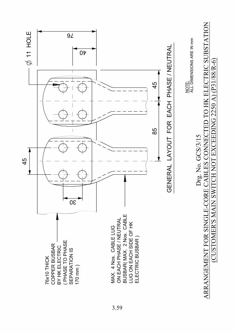
45
85
45
30
40
76
11 H
OLE
GE
NE
RA
L LA
YO
UT
F
OR
E
AC
H P
HA
SE
/ N
EU
TR
AL
76
x1
0 T
HIC
K
CO
PP
ER
B
US
BA
R
BY
H
K E
LE
CT
RIC
( P
HA
SE
T
O P
HA
SE
SE
PA
RA
TIO
N IS
17
0 m
m )
MA
X. 4
N
os. C
AB
LE
L
UG
ON
E
AC
H P
HA
SE
/ N
EU
TR
AL
BU
SB
AR
( M
AX
. 2
N
os. C
AB
LE
LU
G O
N E
AC
H S
ID
E O
F H
K
EL
EC
TR
IC
B
US
BA
R )
Drg
. No.
GC
S/3/
15A
RR
AN
GEM
ENT
FOR
SIN
GLE
-CO
RE
CA
BLE
S C
ON
NEC
TED
TO
HK
ELE
CTR
IC S
UB
STA
TIO
N(C
UST
OM
ER'S
MA
IN S
WIT
CH
NO
T EX
CEE
DIN
G 2
250
A) (
P31/
88/R
-6)
NO
TE
:
AL
L D
IM
EN
SIO
NS
A
RE
IN
m
m
3.59
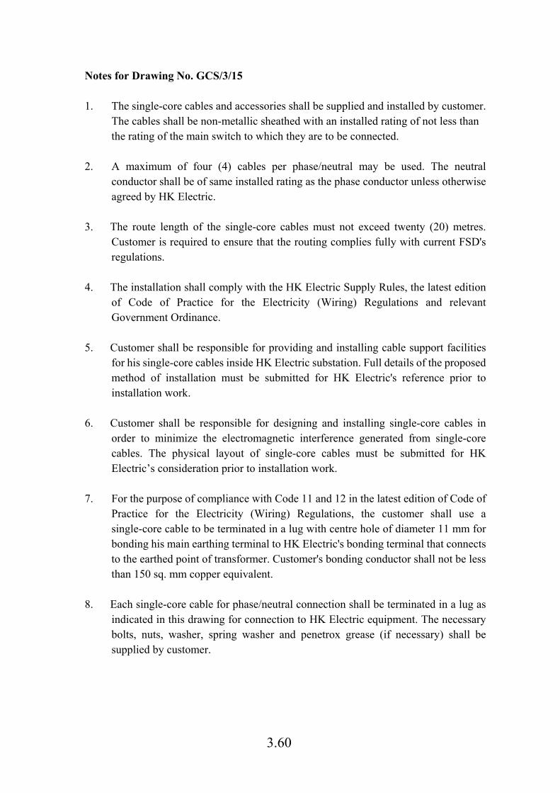
3.60
Notes for Drawing No. GCS/3/15 1. The single-core cables and accessories shall be supplied and installed by customer.
The cables shall be non-metallic sheathed with an installed rating of not less than the rating of the main switch to which they are to be connected.
2. A maximum of four (4) cables per phase/neutral may be used. The neutral conductor shall be of same installed rating as the phase conductor unless otherwise agreed by HK Electric.
3. The route length of the single-core cables must not exceed twenty (20) metres. Customer is required to ensure that the routing complies fully with current FSD's regulations.
4. The installation shall comply with the HK Electric Supply Rules, the latest edition of Code of Practice for the Electricity (Wiring) Regulations and relevant Government Ordinance.
5. Customer shall be responsible for providing and installing cable support facilities for his single-core cables inside HK Electric substation. Full details of the proposed method of installation must be submitted for HK Electric's reference prior to installation work.
6. Customer shall be responsible for designing and installing single-core cables in order to minimize the electromagnetic interference generated from single-core cables. The physical layout of single-core cables must be submitted for HK Electric’s consideration prior to installation work.
7. For the purpose of compliance with Code 11 and 12 in the latest edition of Code of Practice for the Electricity (Wiring) Regulations, the customer shall use a single-core cable to be terminated in a lug with centre hole of diameter 11 mm for bonding his main earthing terminal to HK Electric's bonding terminal that connects to the earthed point of transformer. Customer's bonding conductor shall not be less than 150 sq. mm copper equivalent.
8. Each single-core cable for phase/neutral connection shall be terminated in a lug as indicated in this drawing for connection to HK Electric equipment. The necessary bolts, nuts, washer, spring washer and penetrox grease (if necessary) shall be supplied by customer.
3.61
Notes for Drawing No. GCS/3/15
9. Durable and legible vinyl phase identification labels (such as cable ties, PVC sleeves, PVC ferrule tubes etc.) marked in L1, L2, L3 and N with character size not less than 25 mm shall be provided at the cable ends terminated to HK Electric substation. PVC insulation tape of width not less than 25 mm conforming to BSEN 60454 with phase coding L1, L2, L3 and N could also be used.
10. Termination work of the cable lugs onto HK Electric equipment shall be done by customer's registered electrical worker and under the supervision of HK Electric engineer.
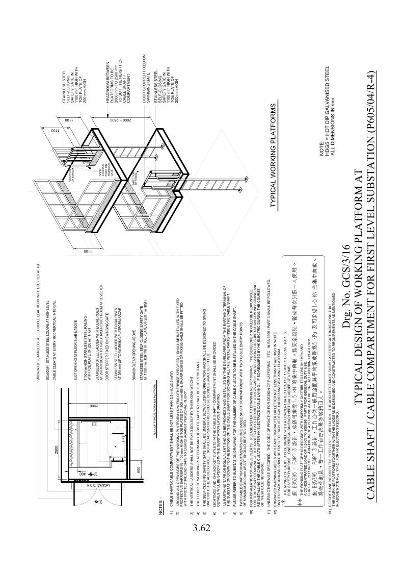
2000 ~ 2500
TYPI
CAL
WO
RKI
NG
PLA
TFO
RM
S
1100
1100
1100
DIR
ECTI
ON
OF
SWIN
G
DIR
ECTI
ON
OF
SWIN
G
DO
OR
STO
PPER
FIXE
D O
NSW
ING
ING
GAT
E
DO
OR
STO
PPER
FIX
ED O
NSW
ING
ING
GAT
E
2500
2500
0.0
0.0
R.C.C. CANOPY
I R
I R
PLAN
OF
TYPI
CAL
WO
RKI
NG
PLA
TFO
RM
SLOT
OPE
NING
AT
FLOO
R SL
AB &
ABO
VE
600x
600(
H) S
TAIN
LESS
STE
EL LO
UVRE
AT
HIGH
LEVE
L
STAI
NLES
S ST
EEL
LADD
ER W
ITH
EQUA
L RI
SES
AT 2
50 m
m D
OWN
TO C
ABLE
RIS
ER D
UCT
ROOM
AT
LEVE
L 0.
0
1100
-mm
HIG
H ST
AINL
ESS
STEE
L RA
ILIN
GW
ITH
TOE
PLAT
E OF
200
mm
HIG
H
600x
600
CLEA
R OP
ENIN
G AB
OVE
STAI
NLES
S ST
EEL
SELF
-CLO
SING
SAF
ETY
GATE
AT 1
100
mm
HIG
H W
ITH
TOE
PLAT
E OF
200
mm
HIG
H
DOOR
STO
PPER
FIX
ED O
N SW
INGI
NG G
ATE
CABL
E CL
EATS
AT
EVER
Y 10
00 V
ERTI
CAL
INTE
RVAL
HEA
DR
OO
M B
ETW
EEN
PLAT
FOR
MS
TO B
E20
00 m
m T
O 2
500
mm
TO S
UIT
TH
E H
EIG
HT
OF
CAB
LE S
HAF
T /
CO
MPA
RTM
ENT
NO
TES:
-
THE
VER
TIC
AL L
ADD
ERS
SHAL
L N
OT
BE F
IXED
SO
LELY
BY
THEI
R O
WN
WEI
GH
T.
THE
RU
NG
S O
F LA
DD
ER IS
DES
IGN
ED W
ITH
A C
ON
CEN
TRAT
ED L
OAD
OF
1.5
KN T
O B
S539
5 : P
ART
3.
THE
WO
RKI
NG
PLA
TFO
RM
IS D
ESIG
NED
WIT
H U
NIF
OR
MLY
DIS
TRIB
UTE
D L
OAD
IN 5
KPa
AN
DA
CO
NC
ENTR
ATED
LO
AD O
F 1.
0 KN
TO
BS5
395
: PAR
T 3
FOR
GEN
ERAL
DU
TY U
SE.
FOR
SAF
ETY
PUR
POSE
, O
NE
PER
SON
ON
EAC
H V
ERTI
CAL
LAD
DER
AT
A TI
ME.
FOR
SAF
ETY
PUR
POSE
, A
MAX
IMU
M O
F 4
PER
SON
S AT
A T
IME
ON
EAC
H W
OR
KIN
G P
LATF
OR
M.
1 )
3)2) 4) 5) 6) 7) 8) 9) 10)
11)
12)
13 )
ARO
UN
D A
LL O
PEN
SID
ES O
F TH
E W
OR
KIN
G P
LATF
OR
M (
UN
LESS
OTH
ERW
ISE
SPEC
IFIE
D )
SH
ALL
BE IN
STAL
LED
WIT
H F
IXED
PRO
TEC
TIVE
BAR
RIE
RS
IN 1
100
mm
HIG
H &
TO
E PL
ATES
OF
200
mm
HIG
H. S
HAR
P ED
GES
OF
FIXI
NG
RAI
LS S
HAL
L BE
FIT
TED
WIT
H P
RO
TEC
TIVE
EN
D C
APS
TO G
UAR
D A
GAI
NST
PER
SON
AL IN
JUR
Y.
THE
FLO
OR
OF
WO
RKI
NG
PLA
TFO
RM
AN
D R
UG
S O
F LA
DD
ER S
HAL
L BE
SLI
P R
ESIS
TAN
T.
THE
SELF
-CLO
SIN
G S
AFET
Y G
ATE
SHAL
L BE
UN
DER
A S
LOW
CLO
SIN
G O
PER
ATIO
N A
ND
SH
ALL
BE D
ESIG
NED
TO
SW
ING
ON
LY IN
TO T
HE
ACC
ESS
HO
LE.
NO
HO
LD-O
PEN
OR
HO
LD-C
LOSE
DEV
ICES
SH
ALL
BE F
ITTE
D.
LIG
HTI
NG
S AN
D 1
3-A
SOC
KET
OU
TLET
S IN
TH
E C
ABLE
SH
AFT
/ CO
MPA
RTM
ENT
SHAL
L BE
PR
OVI
DED
.D
ETAI
LS W
ILL
BE S
PEC
IFIE
D IN
TH
E SU
BSTA
TIO
N L
AYO
UT
DR
AWIN
G.
ENG
RAV
ED W
ARN
ING
LAB
ELS
WIT
H E
ACH
CH
ARAC
TER
OR
LET
TER
NO
T LE
SS T
HAN
15
mm
HIG
H IN
WH
ITE
ON
RED
BAC
KGR
OU
ND
SH
ALL
BE F
IXED
TO
EAC
H V
ERTI
CAL
LAD
DER
AN
D W
OR
KIN
G P
LATF
OR
M.
UN
LESS
OTH
ERW
ISE
SPEC
IFIE
D ,
THE
CO
DE
OF
PRAC
TIC
E FO
R D
ESIG
N O
F PL
ATFO
RM
S ,
ETC
. IN
BS
5395
: PA
RT
3 SH
ALL
BE F
OLL
OW
ED.
PLEA
SE R
EFER
TO
SU
BSTA
TIO
N D
RAW
ING
FO
R T
HE
NU
MBE
R O
F C
ABLE
CLE
ATS
TO B
E IN
STAL
LED
IN T
HE
CAB
LE S
HAF
T.
AN E
ARTH
ING
TAP
E O
R E
QU
IVAL
ENT
SHO
ULD
BE
PRO
VID
ED A
ND
INST
ALLE
D B
Y TH
E D
EVEL
OPE
R F
RO
M T
HE
EAR
THIN
G T
ERM
INAL
OF
THE
SUBS
TATI
ON
DO
WN
TO
TH
E BO
TTO
M O
F TH
E C
ABLE
SH
AFT
FOR
BO
ND
ING
ALL
TH
E M
ETAL
PAR
TS IN
SID
E TH
E C
ABLE
SH
AFT.
2000
x260
0(H)
STA
INLE
SS S
TEEL
DOU
BLE
LEAF
DOO
R W
ITH
LOUV
RES
AT G
/F
STAI
NLES
S ST
EEL
LADD
ER W
ITH
EQUA
L RI
SES
AT 2
50 m
m U
P TO
WOR
KING
PLA
TFOR
M A
BOVE
CAB
LE S
HAF
T/C
ABLE
CO
MPA
RTM
ENT
SHAL
L BE
NO
T LE
SS T
HAN
2.5
m(L
)x2.
5 m
(W)
TWO
CAB
LE S
HAF
TS/C
OM
PAR
TMEN
TS O
R O
NE
CAB
LE S
HAF
T/C
OM
PAR
TMEN
T W
ITH
TW
O C
ABLE
EN
TRY
POIN
TSO
F M
INIM
UM
350
0 m
m A
PAR
T SH
OU
LD B
E PR
OVI
DED
.
BEFO
RE
HAN
DIN
G O
VER
TH
E FI
RST
LEV
EL S
UBS
TATI
ON
, T
HE
ARC
HIT
ECT
MU
ST S
UBM
IT A
CER
TIFI
CAT
E IN
DIC
ATIN
G T
HAT
THE
WO
RKI
NG
PLA
TFO
RM
TO
GET
HER
WIT
H T
HE
LAD
DER
S IS
DES
IGN
ED A
ND
CO
NST
RU
CTE
D T
O R
EQU
IREM
ENTS
AS
MEN
TIO
NED
IN A
BOVE
NO
TE N
os. 1
1-12
FO
R H
K EL
ECTR
IC'S
REC
OR
D.
800
STAI
NLE
SS S
TEEL
SELF
-CLO
SIN
GSA
FETY
GAT
E IN
1100
mm
HIG
H W
ITH
TOE
PLAT
E O
F20
0 m
m H
IGH
STAI
NLE
SS S
TEEL
SELF
-CLO
SIN
GSA
FETY
GAT
E IN
1100
mm
HIG
H W
ITH
TOE
PLAT
E O
F20
0 m
m H
IGH
FOR
INST
ALLA
TIO
N O
F C
ABLE
CLE
ATS
, PL
EASE
REF
ER T
O D
RAW
ING
No.
P67
1/08
/R-3
. T
HE
DEV
ELO
PER
SH
OU
LD B
E R
ESPO
NSI
BLE
FOR
TEM
POR
ARY
REM
OVA
L O
F TH
E C
ABLE
CLE
ATS
FOR
HK
ELEC
TRIC
'S C
ABLE
INST
ALLA
TIO
N F
OR
SU
BSTA
TIO
N C
OM
MIS
SIO
NIN
G A
ND
RE-
INST
ALLI
NG
TH
E C
ABLE
CLE
ATS
AFTE
R H
K EL
ECTR
IC'S
CAB
LE L
AYIN
G ,
IF S
O R
EQU
IRED
BY
HK
ELEC
TRIC
DU
RIN
G T
HE
CO
UR
SEO
F TH
EIR
CAB
LIN
G W
OR
K.
400
NO
TE:
HD
GS
= H
OT
DIP
GAL
VAN
ISED
STE
ELAL
L D
IMEN
SIO
NS
IN m
m
Drg
. No.
GC
S/3/
16TY
PIC
AL
DES
IGN
OF
WO
RK
ING
PLA
TFO
RM
AT
CA
BLE
SH
AFT
/ C
AB
LE C
OM
PAR
TMEN
T FO
R F
IRST
LEV
EL S
UB
STA
TIO
N (P
605/
04/R
-4)
3.62
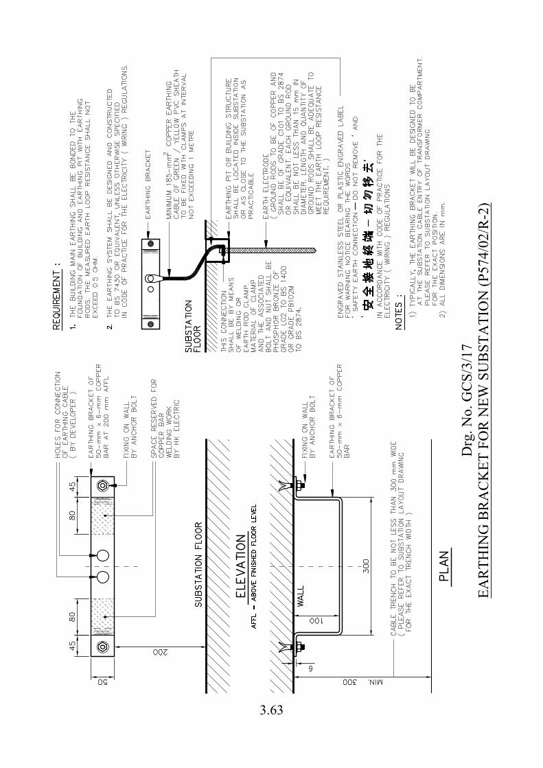
Drg
. No.
GC
S/3/
17EA
RTH
ING
BR
AC
KET
FO
R N
EW S
UB
STA
TIO
N (P
574/
02/R
-2)
3.63
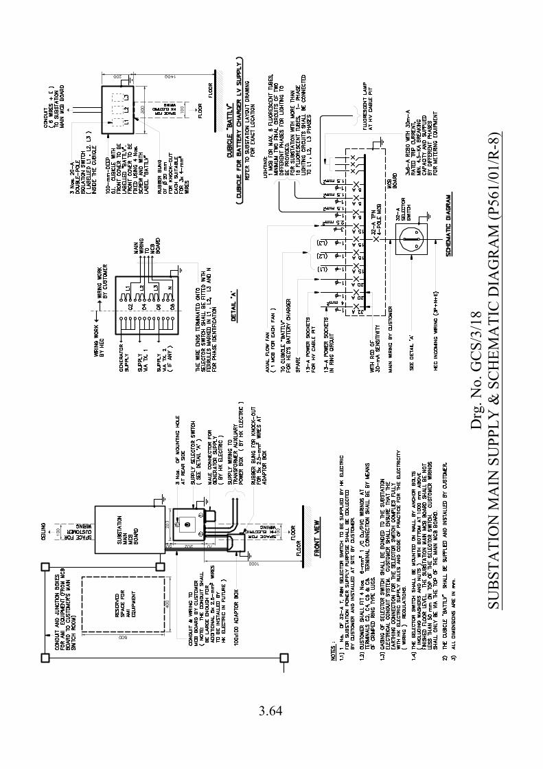
Drg
. No.
GC
S/3/
18SU
BST
ATI
ON
MA
IN S
UPP
LY &
SC
HEM
ATI
C D
IAG
RA
M (P
561/
01/R
-8)
3.64
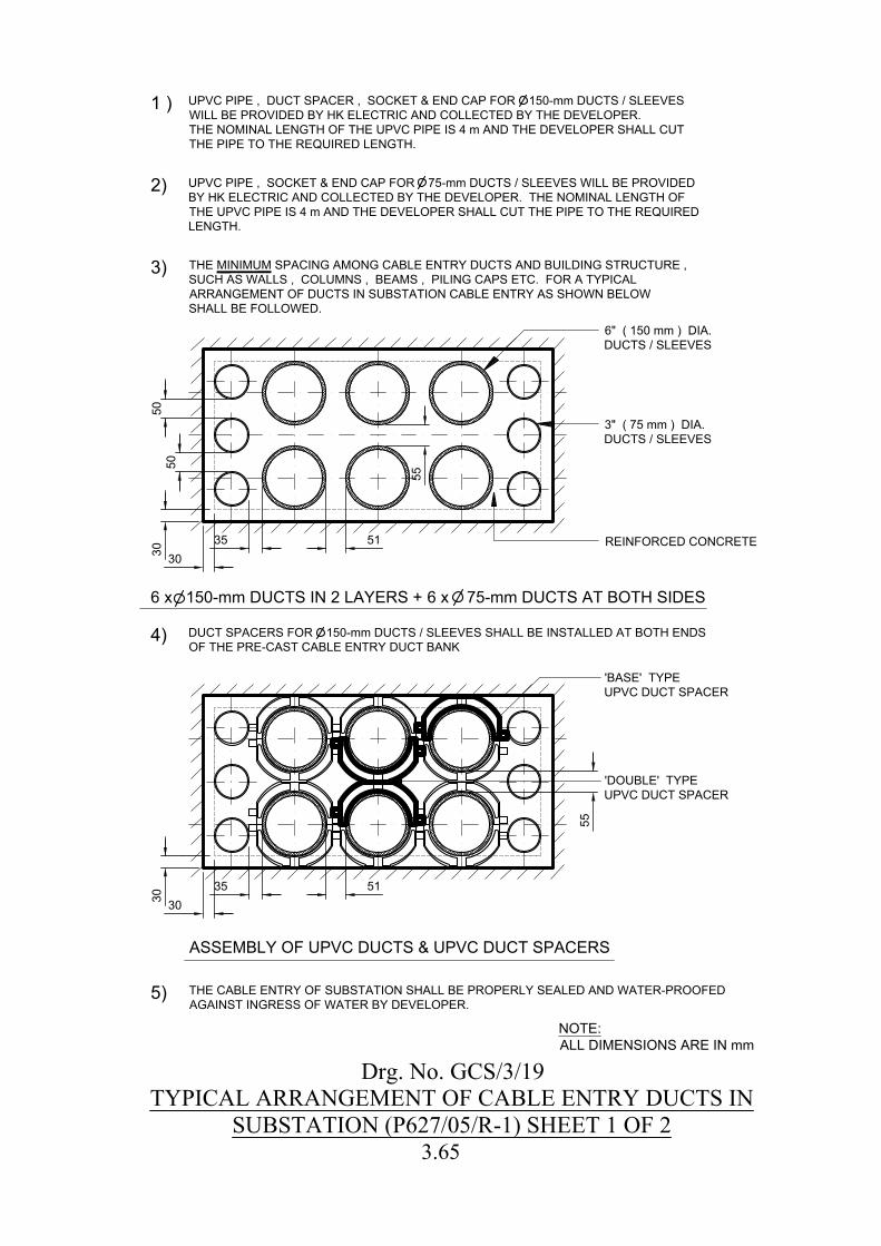
55
35 51
35 51
55
303030 30
5050
1 )
3)
REINFORCED CONCRETE
5) THE CABLE ENTRY OF SUBSTATION SHALL BE PROPERLY SEALED AND WATER-PROOFEDAGAINST INGRESS OF WATER BY DEVELOPER.
4)
ASSEMBLY OF UPVC DUCTS & UPVC DUCT SPACERS
'BASE' TYPEUPVC DUCT SPACER
'DOUBLE' TYPEUPVC DUCT SPACER
DUCT SPACERS FOR 150-mm DUCTS / SLEEVES SHALL BE INSTALLED AT BOTH ENDSOF THE PRE-CAST CABLE ENTRY DUCT BANK
3" ( 75 mm ) DIA.DUCTS / SLEEVES
THE MINIMUM SPACING AMONG CABLE ENTRY DUCTS AND BUILDING STRUCTURE ,SUCH AS WALLS , COLUMNS , BEAMS , PILING CAPS ETC. FOR A TYPICALARRANGEMENT OF DUCTS IN SUBSTATION CABLE ENTRY AS SHOWN BELOWSHALL BE FOLLOWED.
6" ( 150 mm ) DIA.DUCTS / SLEEVES
UPVC PIPE , DUCT SPACER , SOCKET & END CAP FOR 150-mm DUCTS / SLEEVESWILL BE PROVIDED BY HK ELECTRIC AND COLLECTED BY THE DEVELOPER.THE NOMINAL LENGTH OF THE UPVC PIPE IS 4 m AND THE DEVELOPER SHALL CUTTHE PIPE TO THE REQUIRED LENGTH.
2) UPVC PIPE , SOCKET & END CAP FOR 75-mm DUCTS / SLEEVES WILL BE PROVIDEDBY HK ELECTRIC AND COLLECTED BY THE DEVELOPER. THE NOMINAL LENGTH OFTHE UPVC PIPE IS 4 m AND THE DEVELOPER SHALL CUT THE PIPE TO THE REQUIREDLENGTH.
6 x 150-mm DUCTS IN 2 LAYERS + 6 x 75-mm DUCTS AT BOTH SIDES
Drg. No. GCS/3/19TYPICAL ARRANGEMENT OF CABLE ENTRY DUCTS IN
SUBSTATION (P627/05/R-1) SHEET 1 OF 2
NOTE:ALL DIMENSIONS ARE IN mm
3.65
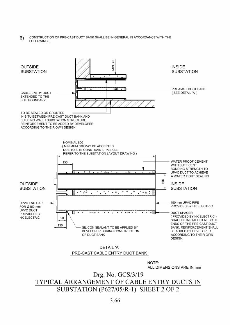
16
5
90
130
150
6)
SILICON SEALANT TO BE APPLIED BY
DEVELOPER DURING CONSTRUCTION
OF DUCT BANK
DETAIL 'A'
INSIDE
SUBSTATION
OUTSIDE
SUBSTATION
OUTSIDE
SUBSTATION
INSIDE
SUBSTATION
CABLE ENTRY DUCT
EXTENDED TO THE
SITE BOUNDARY
MIN
. 7
5
DUCT SPACER
( PROVIDED BY HK ELECTRIC )
SHALL BE INSTALLED AT BOTH
ENDS OF THE PRE-CAST DUCT
BANK. REINFORCEMENT SHALL
BE ADDED BY DEVELOPER
ACCORDING TO THEIR OWN
DESIGN.
NOMINAL 800
( MINIMUM 500 MAY BE ACCEPTED
DUE TO SITE CONSTRAINT, PLEASE
REFER TO THE SUBSTATION LAYOUT DRAWING )
PRE-CAST DUCT BANK
( SEE DETAIL 'A' )
PRE-CAST CABLE ENTRY DUCT BANK
WATER PROOF CEMENT
WITH SUFFICENT
BONDING STRENGTH TO
UPVC DUCT TO ACHIEVE
A WATER TIGHT SEALING
150-mm UPVC PIPE
PROVIDED BY HK ELECTRIC
CONSTRUCTION OF PRE-CAST DUCT BANK SHALL BE IN GENERAL IN ACCORDANCE WITH THE
FOLLOWING :
TO BE SEALED OR GROUTED
IN-SITU BETWEEN PRE-CAST DUCT BANK AND
BUILDING WALL / SUBSTATION STRUCTURE.
REINFORCEMENT TO BE ADDED BY DEVELOPER
ACCORDING TO THEIR OWN DESIGN.
UPVC END CAP
FOR 150-mm
UPVC DUCT
PROVIDED BY
HK ELECTRIC
Drg. No. GCS/3/19TYPICAL ARRANGEMENT OF CABLE ENTRY DUCTS IN
SUBSTATION (P627/05/R-1) SHEET 2 OF 2
NOTE:
ALL DIMENSIONS ARE IN mm
3.66

EL
EV
AT
IO
N ( F
OR
H
EIG
HT
5
m
)
EL
EV
AT
IO
N ( F
OR
H
EIG
HT
>
5
m
)
1000 100
MIN
. 2
00
0
1000 100
SE
PA
RA
TIO
N
BE
TW
EE
N
AD
JA
CE
NT
CA
BLE
C
LE
AT
S
SH
ALL B
E N
OT
LE
SS
T
HA
N 150 m
m
CE
NT
RE
LIN
E
OF
C
AB
LE
SE
PA
RA
TIO
N
BE
TW
EE
N
AD
JA
CE
NT
CA
BLE
C
LE
AT
S
SH
ALL B
E N
OT
LE
SS
T
HA
N 150 m
m
VE
RT
IC
AL O
FF
SE
T
SE
PA
RA
TIO
N
TO
B
E 50 m
m
TW
O-B
OLT
CLE
AT
TR
EF
OIL
CLE
AT
SIN
GLE
-B
OLT
CLE
AT
F
OR
SO
LK
OR
C
AB
LE
CE
NT
RE
LIN
E
OF
C
AB
LE
CA
BLE
S T
O B
E
SU
PP
OR
TE
D
VE
RT
IC
ALLY
IN
S
NA
KIN
G
MA
NN
ER
SIN
GLE
-B
OLT
CLE
AT
TW
O-B
OLT
CLE
AT
SIN
GLE
-B
OLT
CLE
AT
TR
EF
OIL
CLE
AT
SIN
GLE
-B
OLT
CLE
AT
F
OR
SO
LK
OR
C
AB
LE
MIN
. 2
00
0
1000 100 1000 100 1000 100
1000 100 1000 1001000 100
1000 100 1000 100
1000 100 1000 100
PL
AN
480
MIN
. 2
00
0
FL
OO
R
MIN. 800
SP
AC
E B
ET
WE
EN
F
LO
OR
S
TO
B
E F
IT
TE
D / F
ILLE
D W
IT
H
FIR
E R
ES
IS
TA
NT
M
ES
HE
S /
SLA
BS
A
ND
S
EA
LE
D U
P W
IT
H
FIR
E P
RO
TE
CT
IV
E M
OR
TA
R
TO
F
SD
R
EQ
UIR
EM
EN
TS
A
ND
AT
LE
AS
T O
F 2-H
OU
R F
RP
200 m
m(H
)
TO
E B
OA
RD
FU
LL W
ID
TH
AC
CE
SS
PA
NE
L /
DO
OR
I R
Drg
. No.
GC
S/3/
20TY
PIC
AL
AR
RA
NG
EMEN
T O
F C
AB
LES
AN
D C
AB
LE C
LEA
TSIN
RIS
ER D
UC
T (V
ERTI
CA
L H
EIG
HT
7
MET
RE)
(P67
1/08
/R-3
) SH
EET
1 O
F 2
3.67
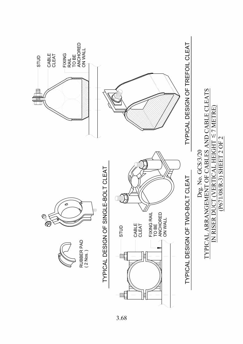
STU
D
TYPI
CAL
DES
IGN
OF
TWO
-BO
LT C
LEAT
CAB
LEC
LEAT
FIXI
NG
RAI
LTO
BE
ANC
HO
RED
ON
WAL
L
TYPI
CAL
DES
IGN
OF
TREF
OIL
CLE
AT
TYPI
CAL
DES
IGN
OF
SIN
GLE
-BO
LT C
LEAT
RU
BBER
PAD
( 2 N
os. )
STU
D
CAB
LEC
LEAT
FIXI
NG
RAI
LTO
BE
ANC
HO
RED
ON
WAL
L
Drg
. No.
GC
S/3/
20TY
PIC
AL
AR
RA
NG
EMEN
T O
F C
AB
LES
AN
D C
AB
LE C
LEA
TSIN
RIS
ER D
UC
T (V
ERTI
CA
L H
EIG
HT
7
MET
RE)
(P67
1/08
/R-3
) SH
EET
2 O
F 2
3.68
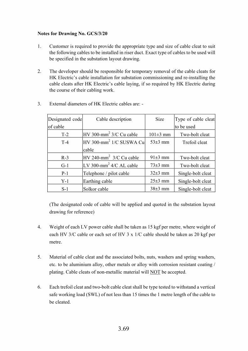
3.69
Notes for Drawing No. GCS/3/20 1. Customer is required to provide the appropriate type and size of cable cleat to suit
the following cables to be installed in riser duct. Exact type of cables to be used will be specified in the substation layout drawing.
2. The developer should be responsible for temporary removal of the cable cleats for
HK Electric’s cable installation for substation commissioning and re-installing the cable cleats after HK Electric’s cable laying, if so required by HK Electric during the course of their cabling work.
3. External diameters of HK Electric cables are: -
Designated code
of cable
Cable description Size Type of cable cleat
to be used
T-2 HV 300-mm2 3/C Cu cable 101±3 mm Two-bolt cleat
T-4 HV 300-mm2 1/C SUSWA Cu
cable
53±3 mm Trefoil cleat
R-3 HV 240-mm2 3/C Cu cable 91±3 mm Two-bolt cleat
G-1 LV 300-mm2 4/C AL cable 73±3 mm Two-bolt cleat
P-1 Telephone / pilot cable 32±3 mm Single-bolt cleat
Y-1 Earthing cable 25±3 mm Single-bolt cleat
S-1 Solkor cable 38±3 mm Single-bolt cleat
(The designated code of cable will be applied and quoted in the substation layout
drawing for reference)
4. Weight of each LV power cable shall be taken as 15 kgf per metre, where weight of
each HV 3/C cable or each set of HV 3 x 1/C cable should be taken as 20 kgf per
metre.
5. Material of cable cleat and the associated bolts, nuts, washers and spring washers,
etc. to be aluminium alloy, other metals or alloy with corrosion resistant coating /
plating. Cable cleats of non-metallic material will NOT be accepted.
6. Each trefoil cleat and two-bolt cable cleat shall be type tested to withstand a vertical
safe working load (SWL) of not less than 15 times the 1 metre length of the cable to
be cleated.
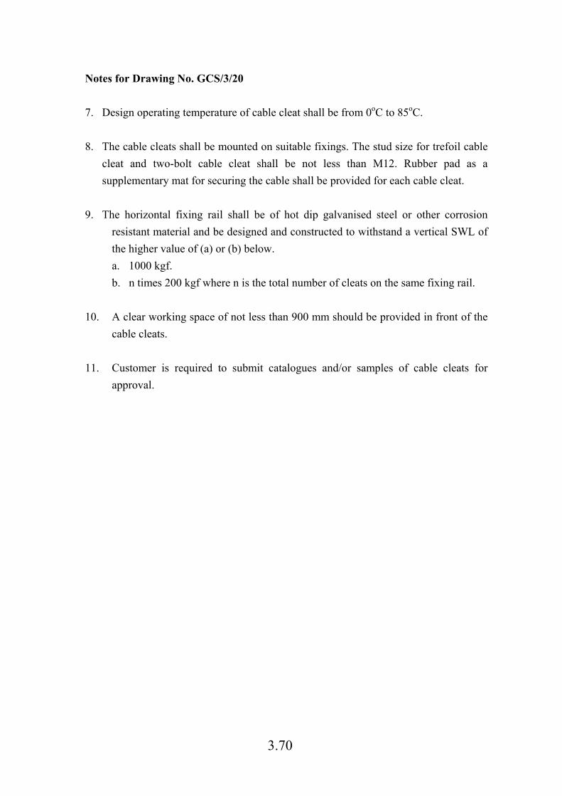
3.70
Notes for Drawing No. GCS/3/20
7. Design operating temperature of cable cleat shall be from 0oC to 85oC.
8. The cable cleats shall be mounted on suitable fixings. The stud size for trefoil cable
cleat and two-bolt cable cleat shall be not less than M12. Rubber pad as a
supplementary mat for securing the cable shall be provided for each cable cleat.
9. The horizontal fixing rail shall be of hot dip galvanised steel or other corrosion
resistant material and be designed and constructed to withstand a vertical SWL of
the higher value of (a) or (b) below.
a. 1000 kgf.
b. n times 200 kgf where n is the total number of cleats on the same fixing rail.
10. A clear working space of not less than 900 mm should be provided in front of the
cable cleats.
11. Customer is required to submit catalogues and/or samples of cable cleats for
approval.
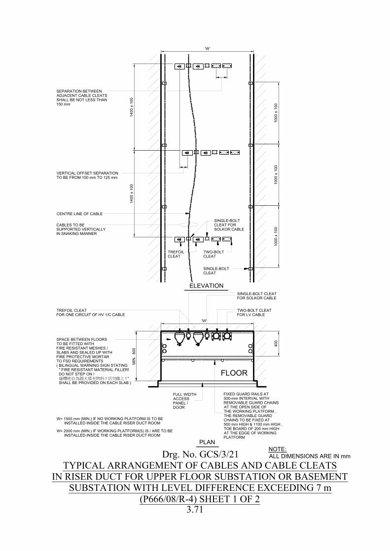
ELEVATION
PLAN
VERTICAL OFFSET SEPARATIONTO BE FROM 100 mm TO 125 mm
CENTRE LINE OF CABLE
CABLES TO BESUPPORTED VERTICALLYIN SNAKING MANNER
TREFOIL CLEATFOR ONE CIRCUIT OF HV 1/C CABLE
FULL WIDTHACCESSPANEL /DOOR
MIN
. 80
0
SINGLE-BOLT CLEATFOR SOLKOR CABLE
TWO-BOLT CLEATFOR LV CABLE
FIXED GUARD RAILS AT500-mm INTERVAL WITHREMOVABLE GUARD CHAINSAT THE OPEN SIDE OFTHE WORKING PLATFORM ,THE REMOVABLE GUARDCHAINS TO BE FIXED AT500 mm HIGH & 1100 mm HIGH ,TOE BOARD OF 200 mm HIGHAT THE EDGE OF WORKINGPLATFORM
SEPARATION BETWEENADJACENT CABLE CLEATSSHALL BE NOT LESS THAN150 mm
SINGLE-BOLTCLEAT
TWO-BOLTCLEAT
SINGLE-BOLTCLEAT FORSOLKOR CABLE
TREFOILCLEAT
1400
± 1
00
1000
± 1
0040
0
'W'
'W'
FLOOR
W= 1500 mm (MIN.) IF NO WORKING PLATFORM IS TO BE INSTALLED INSIDE THE CABLE RISER DUCT ROOM
W= 2000 mm (MIN.) IF WORKING PLATFORM(S) IS / ARE TO BE INSTALLED INSIDE THE CABLE RISER DUCT ROOM
SPACE BETWEEN FLOORSTO BE FITTED WITHFIRE RESISTANT MESHES /SLABS AND SEALED UP WITHFIRE PROTECTIVE MORTARTO FSD REQUIREMENTS( BILINGUAL WARNING SIGN STATING " FIRE RESISTANT MATERIAL FILLER! DO NOT STEP ON ! ! ! " SHALL BE PROVIDED ON EACH SLAB )
1400
± 1
00
1000
± 1
0010
00 ±
100
Drg. No. GCS/3/21TYPICAL ARRANGEMENT OF CABLES AND CABLE CLEATS
IN RISER DUCT FOR UPPER FLOOR SUBSTATION OR BASEMENTSUBSTATION WITH LEVEL DIFFERENCE EXCEEDING 7 m
(P666/08/R-4) SHEET 1 OF 2
NOTE:ALL DIMENSIONS ARE IN mm
3.71
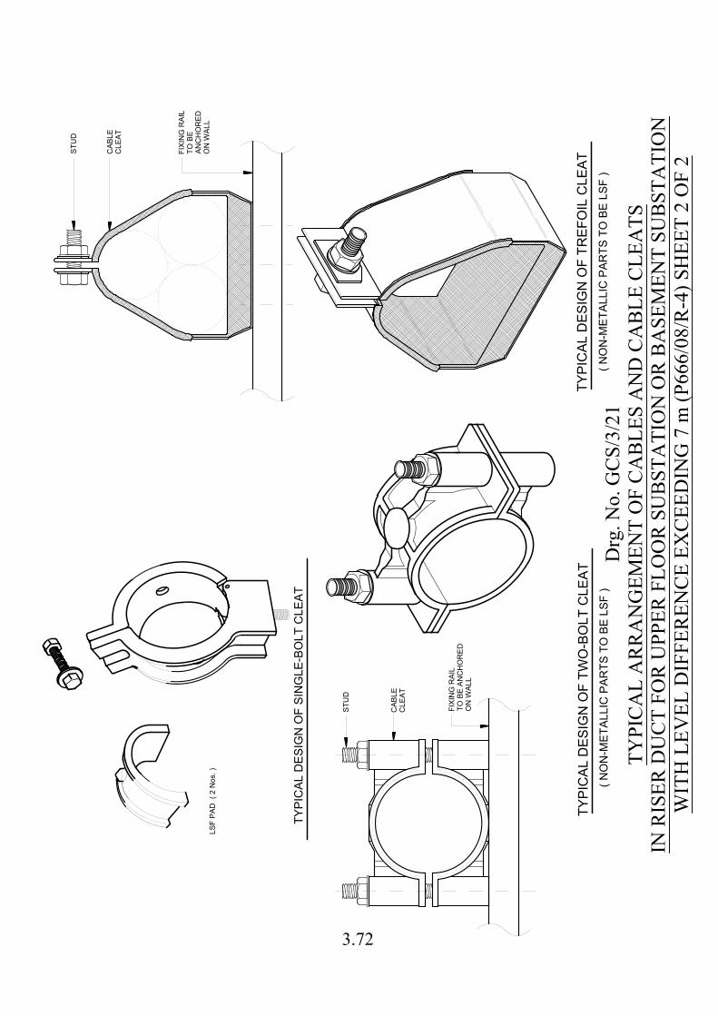
FIX
IN
G R
AIL
TO
B
E
AN
CH
OR
ED
ON
W
AL
L
CA
BL
E
CL
EA
T
ST
UD
TY
PIC
AL D
ES
IG
N O
F T
RE
FO
IL C
LE
AT
( N
ON
-M
ET
AL
LIC
P
AR
TS
T
O B
E L
SF
)
TY
PIC
AL D
ES
IG
N O
F S
IN
GLE
-B
OLT
C
LE
AT
LS
F P
AD
( 2
N
os. )
FIX
IN
G R
AIL
TO
B
E A
NC
HO
RE
D
ON
W
AL
L
CA
BL
E
CL
EA
T
ST
UD
TY
PIC
AL D
ES
IG
N O
F T
WO
-B
OLT
C
LE
AT
( N
ON
-M
ET
AL
LIC
P
AR
TS
T
O B
E L
SF
)
Drg
. No.
GC
S/3/
21TY
PIC
AL
AR
RA
NG
EMEN
T O
F C
AB
LES
AN
D C
AB
LE C
LEA
TSIN
RIS
ER D
UC
T FO
R U
PPER
FLO
OR
SU
BST
ATI
ON
OR
BA
SEM
ENT
SUB
STA
TIO
NW
ITH
LEV
EL D
IFFE
REN
CE
EXC
EED
ING
7 m
(P66
6/08
/R-4
) SH
EET
2 O
F 2
3.72
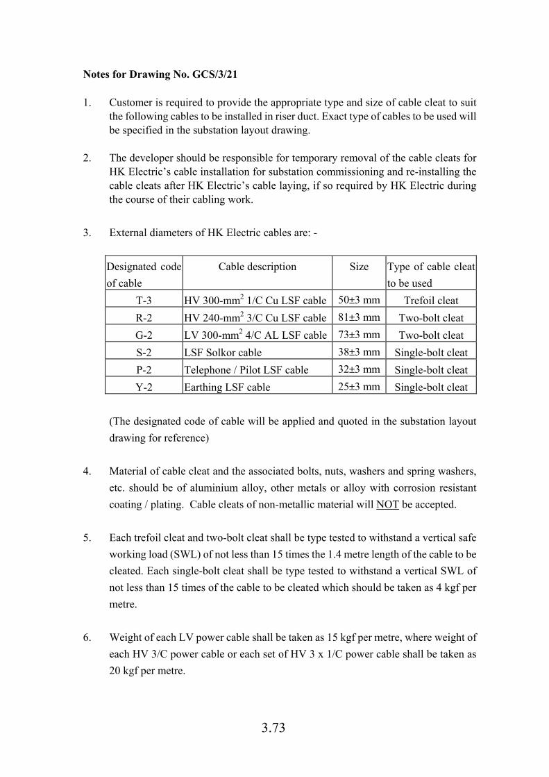
3.73
Notes for Drawing No. GCS/3/21 1. Customer is required to provide the appropriate type and size of cable cleat to suit
the following cables to be installed in riser duct. Exact type of cables to be used will be specified in the substation layout drawing.
2. The developer should be responsible for temporary removal of the cable cleats for
HK Electric’s cable installation for substation commissioning and re-installing the cable cleats after HK Electric’s cable laying, if so required by HK Electric during the course of their cabling work.
3. External diameters of HK Electric cables are: -
Designated code
of cable
Cable description Size Type of cable cleat
to be used
T-3 HV 300-mm2 1/C Cu LSF cable 50±3 mm Trefoil cleat
R-2 HV 240-mm2 3/C Cu LSF cable 81±3 mm Two-bolt cleat
G-2 LV 300-mm2 4/C AL LSF cable 73±3 mm Two-bolt cleat
S-2 LSF Solkor cable 38±3 mm Single-bolt cleat
P-2 Telephone / Pilot LSF cable 32±3 mm Single-bolt cleat
Y-2 Earthing LSF cable 25±3 mm Single-bolt cleat
(The designated code of cable will be applied and quoted in the substation layout
drawing for reference)
4. Material of cable cleat and the associated bolts, nuts, washers and spring washers,
etc. should be of aluminium alloy, other metals or alloy with corrosion resistant
coating / plating. Cable cleats of non-metallic material will NOT be accepted.
5. Each trefoil cleat and two-bolt cleat shall be type tested to withstand a vertical safe
working load (SWL) of not less than 15 times the 1.4 metre length of the cable to be
cleated. Each single-bolt cleat shall be type tested to withstand a vertical SWL of
not less than 15 times of the cable to be cleated which should be taken as 4 kgf per
metre.
6. Weight of each LV power cable shall be taken as 15 kgf per metre, where weight of
each HV 3/C power cable or each set of HV 3 x 1/C power cable shall be taken as
20 kgf per metre.
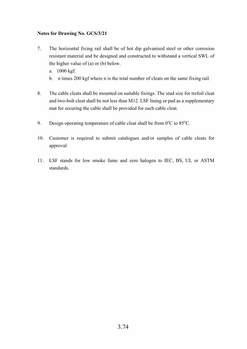
3.74
Notes for Drawing No. GCS/3/21
7. The horizontal fixing rail shall be of hot dip galvanised steel or other corrosion
resistant material and be designed and constructed to withstand a vertical SWL of
the higher value of (a) or (b) below.
a. 1000 kgf.
b. n times 200 kgf where n is the total number of cleats on the same fixing rail.
8. The cable cleats shall be mounted on suitable fixings. The stud size for trefoil cleat
and two-bolt cleat shall be not less than M12. LSF lining or pad as a supplementary
mat for securing the cable shall be provided for each cable cleat.
9. Design operating temperature of cable cleat shall be from 0oC to 85oC.
10. Customer is required to submit catalogues and/or samples of cable cleats for
approval.
11. LSF stands for low smoke fume and zero halogen to IEC, BS, UL or ASTM
standards.

HIG
H L
EV
EL
HA
ZA
RD
Z
ON
E
HIG
H LE
VE
L H
AZ
AR
D Z
ON
E U
NLE
SS
T
HE
Y A
RE
A
T LE
SS
T
HA
N 2300 m
m
SM
OK
E D
ET
EC
TO
R, A
XIA
L F
LO
W F
AN
, F
LE
XIB
LE
C
ON
DU
IT
F
OR
F
AN
A
ND
1. N
O F
LU
OR
ES
CE
NT
LA
MP
F
IT
TIN
G, E
XIT
LIG
HT
F
IT
TIN
G, H
EA
T D
ET
EC
TO
R,
EM
ER
GE
NC
Y P
US
H B
UT
TO
N F
OR
F
AN
S
HA
LL B
E IN
ST
ALLE
D W
IT
HIN
T
HE
2. A
LL D
IM
EN
SIO
NS
A
RE
IN
m
m.
HIG
H W
HE
N M
EA
SU
RE
D F
RO
M S
UB
ST
AT
IO
N F
LO
OR
.
NO
TE
S:
R=
11
50
700
RE
AR
400 780
SW
IT
CH
GE
AR
HV
FR
ON
T
AR
C F
AU
LT
80
0
700
VE
NT
RE
LIE
F
TR
AN
SF
OR
ME
R
R=950
300
70
04
00
1690
HV
C
AB
LE
70
0
BO
X
Drg
. No.
GC
S/3/
22H
IGH
LEV
EL H
AZA
RD
ZO
NE
(P34
6/97
)
3.75
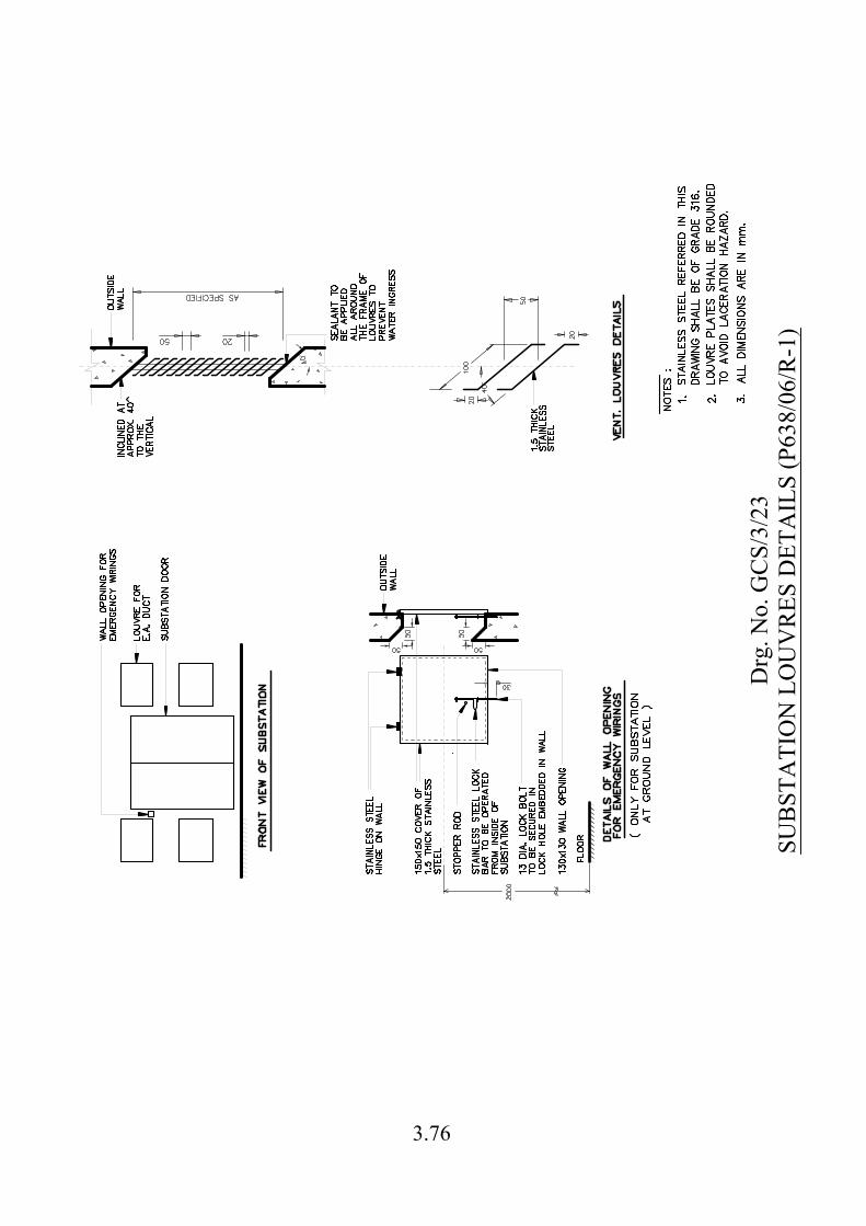
Drg
. No.
GC
S/3/
23SU
BST
ATI
ON
LO
UV
RES
DET
AIL
S (P
638/
06/R
-1)
3.76

3.77
Drg. No. GCS/3/24
INFORMATION ON APPLICATION FOR EXCAVATION PERMIT SHEET 1 OF 2
香港電燈有限公司 THE HONGKONG ELECTRIC CO., LTD.
Do you know that HK Electric has to apply for an Excavation Permit from Highways Department of HKSAR Government before laying a cable to make electricity available to you? Here are some facts on how HK Electric applies for the Excavation Permit, how much it costs to HK Electric and how long it will take. Summary of amended Ordinance effective on 1st April 2004 for Excavations in Public Streets and Footpaths All excavations are controlled under the Land (Miscellaneous
Provisions) Ordinance, Cap. 28.
An Excavation Permit is required for excavations in unleased Government land, otherwise a fine up to $50,000 and an imprisonment for 6 months can be imposed. In majority of cases, HK Electric applies for Excavation Permit from Highways Department*. * For minority of cases, HK Electric has to apply for permit from other Government authority.
Fees to be paid by HK Electric for each Excavation Permit granted by
Highways Department.
Application Fee HK$2,050 / permit
Daily Fee HK$35 / day
Extension Fee HK$650 / permit
Unless with accepted reasons, a daily economic cost will be charged
to HK Electric if HK Electric does not complete the excavations involving carriageway on time and extension is required.
Strategic Streets HK$21,000 / day
Sensitive Streets HK$8,540 / day
Streets other than the above two classes HK$1,710 / day

3.78
Drg. No. GCS/3/24 INFORMATION ON APPLICATION FOR EXCAVATION PERMIT
SHEET 2 OF 2
Time required for HK Electric to register and submit an application for an Excavation Permit before work commencement: 1. Minimum Registration Lead Time:
Works on carriageway of trunk roads or works on any carriageway exceeding 3 months
6 months
Works on carriageway other than trunk roads not exceeding 3 months or works not on carriageway but exceeding 3 months
2 months
Works not on carriageway and not exceeding 3 months 1 month
2. HK Electric is also required to coordinate with other utility undertakers for the program of work such that the overall disturbance brought to the public will be kept to a minimum before Highways Department granting the Excavation Permit. These utility undertakers include the telecommunication service companies, Gas Company, Drainage Service Department, Water Supplies Department, and etc. Also, Highways Department imposes a 3-month excavation restriction period after excavation by all other Utilities Undertakings to avoid repeated excavation in the same location. A 6-month restriction period will be imposed by Highways Department after excavation by HK Electric at the same location.
3. HK Electric has to obtain consent from Transport Department and Hong Kong Police Force of the proposed excavation work before Highways Department grants the Excavation Permit to HK Electric. With the current arrangement, Transport Department and Hong Kong Police Force will only provide comments to HK Electric’s excavation proposals for the excavation works in Traffic Management Liaison Group Meeting (TMLG Meeting) with limited meeting time each month.
4. HK Electric may be required to approach the following parties for their comments or consent of the excavation work before Highways Department grants the Excavation Permit to HK Electric:
Environmental Protection Department MTR Corporation Limited
Leisure and Culture Services Department E&M Services Department
Architectural Services Department
5. Overall time required for obtaining an Excavation Permit from Highways Department:
More than 10 weeks (excluding the registration time) for a typical case in footpath.
For more information: You may visit the website of Highways Department http://www.hyd.gov.hk for more details on Excavation Permit.
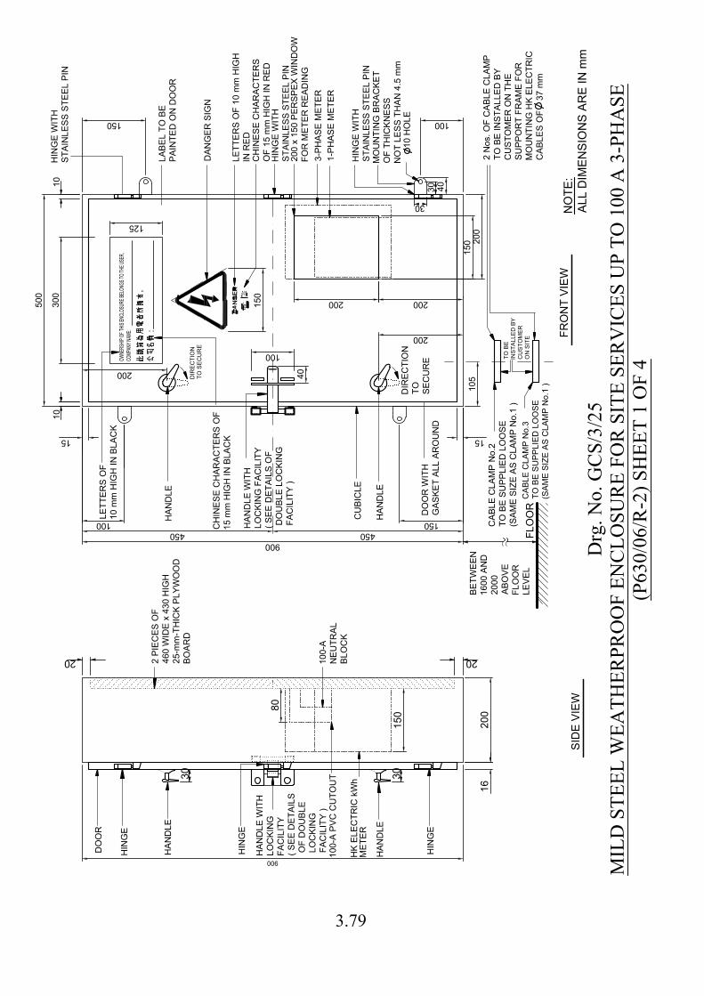
900
1515
100 150
150 100
15
0
80
20
01
6
40
50
0
30
0
125
900
450
40
10
5
100
200
200
15
0
15
0
20
0
200
CU
BIC
LE
DO
OR
W
IT
H
GA
SK
ET
A
LL
A
RO
UN
D
FR
ON
T V
IE
W
DIR
EC
TIO
N
TO
S
EC
UR
E
10
10
SID
E V
IE
W
HIN
GE
HIN
GE
DO
OR
30
1
0 H
OL
E
MO
UN
TIN
G B
RA
CK
ET
OF
T
HIC
KN
ES
S
NO
T L
ES
S T
HA
N 4
.5
m
m
BE
TW
EE
N
16
00
A
ND
20
00
AB
OV
E
FL
OO
R
LE
VE
L
FL
OO
R
30
30
:
,
DA
NG
ER
S
IG
N
LA
BE
L T
O B
E
PA
IN
TE
D O
N D
OO
R
CH
IN
ES
E C
HA
RA
CT
ER
S O
F
15
m
m H
IG
H IN
B
LA
CK
HK
E
LE
CT
RIC
kW
h
30
HIN
GE
W
IT
H
ST
AIN
LE
SS
S
TE
EL
P
IN
10
0-A
NE
UT
RA
L
BL
OC
K
HA
ND
LE
HA
ND
LE
HA
ND
LE
W
IT
H
LO
CK
IN
G F
AC
IL
IT
Y
( S
EE
D
ET
AIL
S O
F
D
OU
BL
E L
OC
KIN
G
F
AC
IL
IT
Y )
HA
ND
LE
HA
ND
LE
HA
ND
LE
W
IT
H
LO
CK
IN
G
FA
CIL
IT
Y
( S
EE
D
ET
AIL
S
O
F D
OU
BL
E
L
OC
KIN
G
F
AC
IL
IT
Y )
20
CA
BL
E C
LA
MP
N
o.2
TO
B
E S
UP
PL
IE
D L
OO
SE
(S
AM
E S
IZ
E A
S C
LA
MP
N
o.1
)
CA
BLE
C
LA
MP
N
o.3
TO
B
E S
UP
PLIE
D LO
OS
E
(S
AM
E S
IZ
E A
S C
LA
MP
N
o.1 )
20
0 x 1
50
P
ER
SP
EX
W
IN
DO
W
FO
R M
ET
ER
R
EA
DIN
G
2 N
os. O
F C
AB
LE
C
LA
MP
TO
B
E IN
ST
AL
LE
D B
Y
CU
ST
OM
ER
O
N T
HE
SU
PP
OR
T F
RA
ME
F
OR
MO
UN
TIN
G H
K E
LE
CT
RIC
CA
BL
ES
O
F 3
7 m
m
OW
NE
RS
HIP
O
F T
HIS
E
NC
LO
SU
RE
B
ELO
NG
S T
O T
HE
U
SE
R,
CO
MP
AN
Y N
AM
E:
DIR
EC
TIO
N
TO
SE
CU
RE
LE
TT
ER
S O
F
10
m
m H
IG
H IN
B
LA
CK
TO
B
E
IN
ST
ALLE
D B
Y
CU
ST
OM
ER
ON
S
IT
E
HIN
GE
W
IT
H
ST
AIN
LE
SS
S
TE
EL
P
IN
LE
TT
ER
S O
F 1
0 m
m H
IG
H
IN
R
ED
CH
IN
ES
E C
HA
RA
CT
ER
S
OF
1
5 m
m H
IG
H IN
R
ED
HIN
GE
HIN
GE
W
IT
H
ST
AIN
LE
SS
S
TE
EL
P
IN
2 P
IE
CE
S O
F
46
0 W
ID
E x 4
30
H
IG
H
25
-m
m-T
HIC
K P
LY
WO
OD
BO
AR
D
20
3-P
HA
SE
M
ET
ER
1-P
HA
SE
M
ET
ER
10
0-A
P
VC
C
UT
OU
T
450
200
ME
TE
R
Drg
. No.
GC
S/3/
25M
ILD
STE
EL W
EATH
ERPR
OO
F EN
CLO
SUR
E FO
R S
ITE
SER
VIC
ES U
P TO
100
A 3
-PH
ASE
(P63
0/06
/R-2
) SH
EET
1 O
F 4
NO
TE
:
AL
L D
IM
EN
SIO
NS
A
RE
IN
m
m
3.79
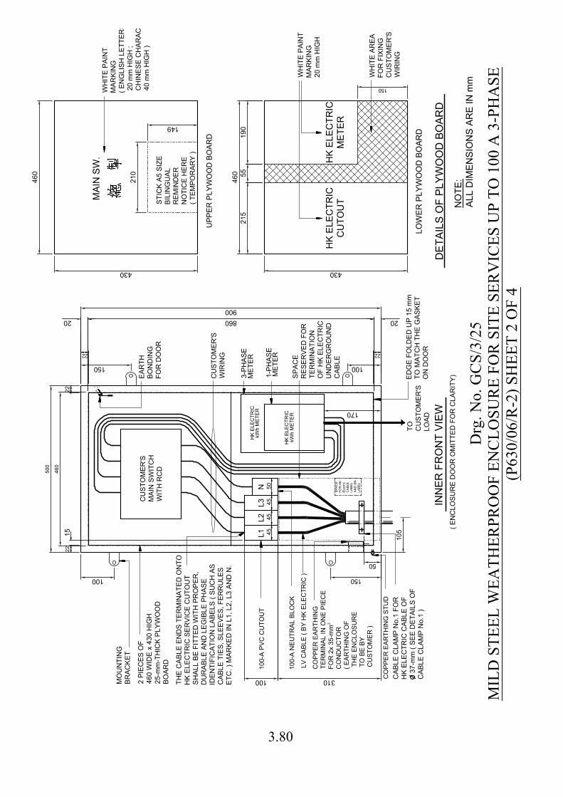
900
100 150
150 100
310
500
105
50
460
20 20860
170
430
21
55
5
46
0
430
46
0
149
21
0
150
L1
L2
L3
N
22 22
45
45
45
50
22
22
15
ED
GE
F
OL
DE
D U
P 1
5 m
m
TO
M
AT
CH
T
HE
G
AS
KE
T
ON
D
OO
R
2
100-A
N
EU
TR
AL B
LO
CK
IN
NE
R F
RO
NT
V
IE
W
HK
E
LE
CT
RIC
100-A
P
VC
C
UT
OU
T
LV
C
AB
LE
( B
Y H
K E
LE
CT
RIC
)
MO
UN
TIN
G
BR
AC
KE
T
CU
ST
OM
ER
'S
WIR
IN
G
TO
CU
ST
OM
ER
'S
LO
AD
CA
BL
E C
LA
MP
N
o.1
F
OR
HK
E
LE
CT
RIC
C
AB
LE
O
F
3
7-m
m ( S
EE
D
ET
AIL
S O
F
CA
BL
E C
LA
MP
N
o.1
)
SP
AC
E
RE
SE
RV
ED
F
OR
TE
RM
IN
AT
IO
N
OF
H
K E
LE
CT
RIC
UN
DE
RG
RO
UN
D
CA
BL
E
SP
AC
E
FO
R H
K
Electric
CA
BLE
LA
BE
L
AN
D S
N
LA
BE
L
CO
PP
ER
E
AR
TH
IN
G
TE
RM
IN
AL IN
O
NE
P
IE
CE
FO
R 2x 35-m
m
CO
ND
UC
TO
R
( E
AR
TH
IN
G O
F
T
HE
E
NC
LO
SU
RE
T
O B
E B
Y
C
US
TO
ME
R )
CO
PP
ER
E
AR
TH
IN
G S
TU
D
EA
RT
H
BO
ND
IN
G
FO
R D
OO
R
HK
E
LE
CT
RIC
2 P
IE
CE
S O
F
46
0 W
ID
E x 4
30
H
IG
H
25
-m
m-T
HIC
K P
LY
WO
OD
BO
AR
D
CU
ST
OM
ER
'S
MA
IN
S
WIT
CH
WIT
H R
CD
HK
E
LE
CT
RIC
CU
TO
UT
HK
E
LE
CT
RIC
ME
TE
R
LO
WE
R P
LY
WO
OD
B
OA
RD
WH
IT
E P
AIN
T
MA
RK
IN
G
20
m
m H
IG
H
UP
PE
R P
LY
WO
OD
B
OA
RD
MA
IN
S
W.
WH
IT
E P
AIN
T
MA
RK
IN
G
( E
NG
LIS
H L
ET
TE
RS
2
0 m
m H
IG
H ;
C
HIN
ES
E C
HA
RA
CT
ER
S
4
0 m
m H
IG
H )
DE
TA
ILS
O
F P
LY
WO
OD
B
OA
RD
ST
IC
K A
5 S
IZ
E
BIL
IN
GU
AL
RE
MIN
DE
R
NO
TIC
E H
ER
E
( T
EM
PO
RA
RY
)
WH
IT
E A
RE
A
FO
R F
IX
IN
G
CU
ST
OM
ER
'S
WIR
IN
G
3-P
HA
SE
ME
TE
R
TH
E C
AB
LE
E
ND
S T
ER
MIN
AT
ED
O
NT
O
HK
E
LE
CT
RIC
S
ER
VIC
E C
UT
OU
T
SH
AL
L B
E F
IT
TE
D W
IT
H P
RO
PE
R,
DU
RA
BL
E A
ND
L
EG
IB
LE
P
HA
SE
ID
EN
TIF
IC
AT
IO
N L
AB
EL
S ( S
UC
H A
S
CA
BL
E T
IE
S, S
LE
EV
ES
, F
ER
RU
LE
S
ET
C. ) M
AR
KE
D IN
L
1, L
2, L
3 A
ND
N
.
100
19
0
ME
TE
R
1-P
HA
SE
( E
NC
LO
SU
RE
D
OO
R O
MIT
TE
D F
OR
C
LA
RIT
Y)
kW
h M
ET
ER
kW
h M
ET
ER
Drg
. No.
GC
S/3/
25M
ILD
STE
EL W
EATH
ERPR
OO
F EN
CLO
SUR
E FO
R S
ITE
SER
VIC
ES U
P TO
100
A 3
-PH
ASE
(P63
0/06
/R-2
) SH
EET
2 O
F 4
NO
TE
:
AL
L D
IM
EN
SIO
NS
A
RE
IN
m
m
3.80
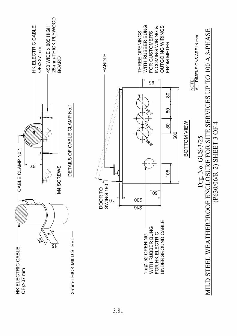
16
50
0
95
15
2
5
10
5
60
80
BO
TT
OM
V
IE
W
HA
ND
LE
DO
OR
T
O
SW
IN
G 1
80
200
216
1 x 5
2 O
PE
NIN
G
WIT
H R
UB
BE
R B
UN
G
FO
R H
K E
LE
CT
RIC
UN
DE
RG
RO
UN
D C
AB
LE
DE
TA
IL
S O
F C
AB
LE
C
LA
MP
N
o.1
CA
BL
E C
LA
MP
N
o.1
HK
E
LE
CT
RIC
C
AB
LE
OF
3
7 m
m
HK
E
LE
CT
RIC
C
AB
LE
OF
3
7 m
m
3-m
m-T
HIC
K M
IL
D S
TE
EL
M4
S
CR
EW
S
37
TH
RE
E O
PE
NIN
GS
WIT
H R
UB
BE
R B
UN
G
FO
R C
US
TO
ME
R'S
IN
CO
MIN
G W
IR
IN
G &
OU
TG
OIN
G W
IR
IN
GS
FR
OM
M
ET
ER
6
4
6
4
6
4
45
0 W
ID
E x 8
85
H
IG
H
25
-m
m-T
HIC
K P
LY
WO
OD
BO
AR
D
80
80
Drg
. No.
GC
S/3/
25M
ILD
STE
EL W
EATH
ERPR
OO
F EN
CLO
SUR
E FO
R S
ITE
SER
VIC
ES U
P TO
100
A 3
-PH
ASE
(P63
0/06
/R-2
) SH
EET
3 O
F 4
NO
TE
:
AL
L D
IM
EN
SIO
NS
A
RE
IN
m
m
3.81
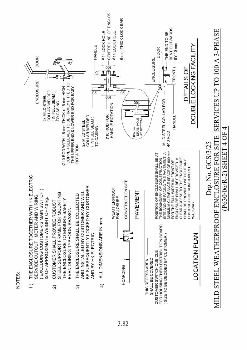
100
20 20
40
100
100
HO
AR
DIN
G
CO
NS
TR
UC
TIO
N S
IT
E
PA
VE
ME
NT
LO
CA
TIO
N P
LA
N
WE
AT
HE
RP
RO
OF
EN
CLO
SU
RE
TH
IS
R
EC
ES
S A
RE
A
SH
AL
L B
E C
OV
ER
ED
CU
ST
OM
ER
S
HA
LL
P
RO
VID
E R
OB
US
T
ST
EE
L S
UP
PO
RT
F
RA
ME
F
OR
M
OU
NT
IN
G
TH
E E
NC
LO
SU
RE
T
O E
NS
UR
E S
AF
ET
Y
EV
EN
D
UR
IN
G T
YP
HO
ON
S
EA
SO
N.
1 )
2)
3)
DE
TA
IL
S O
F
DO
UB
LE
L
OC
KIN
G F
AC
IL
IT
Y
( F
RO
NT
)
EN
CLO
SU
RE
6-m
m-T
HIC
K L
OC
K B
AR
14
L
OC
K H
OL
E
CE
NT
RE
L
IN
E O
F E
NC
LO
SU
RE
14
L
OC
K H
OL
E
HA
ND
LE
1
0 R
OD
F
OR
HA
ND
LE
R
OT
AT
IO
N
HA
ND
LE
TH
E E
ND
T
O B
E
BE
NT
O
UT
WA
RD
S
BY
1
0 m
m
TH
E E
NC
LO
SU
RE
S
HA
LL
B
E C
OL
LE
CT
ED
AN
D IN
ST
AL
LE
D B
Y C
US
TO
ME
R A
ND
W
IL
L
BE
S
UB
SE
QU
EN
TL
Y L
OC
KE
D B
Y C
US
TO
ME
R
AN
D B
Y H
K E
LE
CT
RIC
.
CU
ST
OM
ER
S
WIT
CH
C
UB
IC
LE
FO
R H
OU
SIN
G T
HE
IR
D
IS
TR
IB
UT
IO
N B
OA
RD
( S
IZ
E T
O B
E D
EC
ID
ED
B
Y C
US
TO
ME
R )
2x M
IL
D S
TE
EL
CO
LL
AR
W
EL
DE
D
( IN
F
UL
L S
EA
M )
TO
C
AS
IN
G
DO
OR
3
-m
m
DR
AIN
H
OL
E
AT
B
OT
TO
M
MIL
D S
TE
EL C
OL
LA
R F
OR
10
R
OD
EN
CL
OS
UR
E
DO
OR
2x M
IL
D S
TE
EL
CO
LL
AR
W
EL
DE
D
( IN
F
UL
L S
EA
M )
TO
C
AS
IN
G
10
R
OD
W
IT
H 1
.5
-m
m-T
HIC
K x 1
5-m
m-H
IG
H
CO
PP
ER
S
LE
EV
ES
T
O B
E F
IR
ML
Y F
IT
TE
D T
O
TH
E U
PP
ER
E
ND
&
L
OW
ER
E
ND
F
OR
E
AS
Y
RO
TA
TIO
N
TH
E E
NC
LO
SU
RE
T
OG
ET
HE
R W
IT
H H
K E
LE
CT
RIC
SE
RV
IC
E C
UT
OU
T , M
ET
ER
A
ND
W
IR
IN
G
( E
XC
LU
DIN
G C
US
TO
ME
R'S
M
AIN
S
WIT
CH
)
IS
O
F A
PP
RO
XIM
AT
E W
EIG
HT
O
F 4
0 kg
.
NO
TE
S:
PO
SIT
IO
N O
F E
NC
LO
SU
RE
S
HA
LL
B
E A
T
TH
E B
OU
ND
AR
Y O
F C
ON
ST
RU
CT
IO
N
SIT
E A
ND
B
E F
AC
IN
G T
HE
P
AV
EM
EN
T. A
MIN
IM
UM
C
LE
AR
AN
CE
S
PA
CE
O
F 9
00
m
m
FO
R T
HE
F
UL
L W
ID
TH
IN
F
RO
NT
O
F
EN
CL
OS
UR
E S
HA
LL
B
E P
RO
VID
ED
. A
CL
EA
R A
CC
ES
S T
O T
HE
E
NC
LO
SU
RE
SH
AL
L B
E P
RO
VID
ED
W
IT
HO
UT
A
NY
OB
ST
RU
CT
IO
N F
RO
M C
OV
ER
ED
WA
LK
WA
Y.
4)
AL
L D
IM
EN
SIO
NS
A
RE
IN
m
m.
Drg
. No.
GC
S/3/
25M
ILD
STE
EL W
EATH
ERPR
OO
F EN
CLO
SUR
E FO
R S
ITE
SER
VIC
ES U
P TO
100
A 3
-PH
ASE
(P63
0/06
/R-2
) SH
EET
4 O
F 4
3.82

1.In
gen
eral
the
oper
atio
n of
a s
ubst
atio
n do
or w
ith d
ecor
atio
ncl
addi
ng o
r a d
ecor
ativ
e do
or in
add
ition
to th
e st
anda
rdsu
bsta
tion
door
wou
ld o
ccup
y m
uch
larg
er a
rea
of p
avem
ent i
nfro
nt o
f the
sub
stat
ion.
Any
suc
h de
cora
tive
feat
ures
on
the
subs
tatio
n do
or o
r the
add
ition
of a
dec
orat
ive
door
sho
uld
beav
oide
d as
far a
s pr
actic
able
from
ope
ratio
nal p
oint
of v
iew
.In
cas
e an
y su
bsta
tion
door
is o
f suc
h de
sign
and
/ or
an
addi
tiona
l dec
orat
ive
door
in fr
ont o
f the
sub
stat
ion
door
ispr
opos
ed, H
K El
ectri
c sh
all h
ave
the
disc
retio
n on
the
acce
ptan
ce o
f suc
h pr
opos
al d
epen
ding
on
the
actu
al s
itesi
tuat
ion.
The
arc
hite
ct /
deve
lope
r sha
ll su
bmit
thei
rpr
opos
al in
the
subs
tatio
n de
sign
sta
ge fo
r HK
Elec
tric’
sco
nsid
erat
ion.
Thi
s dr
awin
g de
pict
s on
ly th
e ge
nera
l con
ditio
nson
acc
epta
nce
of a
n ad
ditio
nal d
ecor
ativ
e do
or in
fron
t of t
hesu
bsta
tion
door
of a
gro
und
floor
sub
stat
ion
and
/ or a
ttach
ing
exte
rnal
dec
orat
ive
clad
ding
to s
ubst
atio
n do
or fo
r ref
eren
cepu
rpos
e.
2.G
ener
al re
quire
men
ts fo
r bot
h th
e su
bsta
tion
door
with
deco
ratio
n cl
addi
ng a
nd th
e ad
ditio
nal d
ecor
ativ
e do
or in
fron
tof
the
stan
dard
sub
stat
ion
door
of a
sub
stat
ion
at g
roun
d flo
or
2.1
A ca
nopy
abo
ve th
e su
bsta
tion
door
sha
ll be
pro
vide
dac
cord
ing
to H
K El
ectri
c dr
awin
g.
2.2
A sp
ace
of n
ot le
ss th
an 1
,000
mm
(H) x
600
mm
(W) a
t 1,4
00 m
mce
ntre
abo
ve p
avem
ent l
evel
, with
pro
per m
ount
ing
faci
litie
ssh
all b
e pr
ovid
ed fo
r mou
ntin
g th
e su
bsta
tion
nam
e pl
ates
and
war
ning
sig
n on
ext
erna
l sur
face
of t
he d
oor.
2.3
The
prop
osed
add
ition
al d
oor o
r dec
orat
ive
louv
res/
clad
ding
on th
e st
anda
rd s
ubst
atio
n do
or s
hall
not r
esul
t in
any
adve
rse
effe
ct o
n th
e su
bsta
tion
vent
ilatio
n sy
stem
and
a m
inim
um fl
owra
te a
s st
ipul
ated
in th
e su
bsta
tion
layo
ut d
raw
ing
shal
l be
achi
eved
whe
n th
e su
bsta
tion
vent
ilatio
n sy
stem
is o
pera
ting.
Asi
te m
easu
rem
ent i
s re
quire
d to
con
firm
com
plia
nce
afte
r the
deco
rativ
e lo
uvre
s/cl
addi
ng o
r the
add
ition
al d
ecor
ativ
e do
or is
inst
alle
d.
2.4
In c
ase
ther
e is
any
def
ect/m
alfu
nctio
n of
the
subs
tatio
nve
ntila
tion
syst
em w
hich
may
affe
ct th
e su
bsta
tion
tem
pera
ture
,th
e de
velo
per s
hall
be re
spon
sibl
e fo
r kee
ping
the
addi
tiona
ldo
or fu
lly o
pen
(or d
ism
antli
ng th
e ad
ditio
nal d
oor i
f kee
ping
the
addi
tiona
l doo
r ope
n in
a p
rolo
nged
man
ner i
s no
t allo
wed
due
to th
e po
ssib
le o
bstru
ctio
n at
site
) / d
etac
hing
the
deco
rativ
e lo
uvre
s/cl
addi
ng fr
om th
e su
bsta
tion
door
tofa
cilit
ate
the
air c
ircul
atio
n up
on re
ques
t by
HK
Elec
tric.
2.5
A co
nfirm
atio
n le
tter s
hall
be p
rovi
ded
from
the
deve
lope
rto
und
erta
ke th
e re
spon
sibi
litie
s fo
r fut
ure
repa
ir /
mai
nten
ance
of t
he a
dditi
onal
sub
stat
ion
door
and
the
prop
osed
deco
rativ
e lo
uvre
s/cl
addi
ng o
n th
e su
bsta
tion
door
in c
ase
ofda
mag
e by
HK
Elec
tric
durin
g in
itial
equ
ipm
ent d
eliv
ery
and
futu
re tr
ansp
orta
tion
of s
uppl
y ap
para
tus
to a
nd fr
om th
esu
bsta
tion.
The
lette
r sha
ll al
so c
onfir
m th
eir c
ompl
ianc
e w
ithal
l the
requ
irem
ents
stip
ulat
ed in
this
Dra
win
g.
2.6
Subs
tatio
n D
oor S
win
g
The
subs
tatio
n do
or s
hall
be a
ble
to fu
lly o
pen
with
180
deg
ree
swin
g w
ith a
cle
ar o
peni
ng o
f not
less
than
2.0
m (W
) x 2
.6 m
(H)
afte
r the
sub
stat
ion
door
and
the
addi
tiona
l dec
orat
ive
door
have
bee
n fu
lly o
pene
d fo
r tra
nspo
rtatio
n of
HK
Elec
tric’
seq
uipm
ent t
o an
d fro
m th
e su
bsta
tion.
A 1
50 d
egre
e sw
ing
of th
esu
bsta
tion
door
whi
le m
aint
aini
ng a
cle
ar o
peni
ng o
f not
less
than
2.0
m (W
) x 2
.6 m
(H) w
ill al
so b
e ac
cept
able
pro
vide
d th
efo
llow
ing
cond
ition
s ar
e m
et:
(i)Th
e su
bsta
tion
door
and
the
addi
tiona
l dec
orat
ive
door
, whe
nbe
ing
open
ed o
utw
ards
ove
r any
stre
et, m
ust n
ot c
ause
an
obst
ruct
ion
to a
ny p
erso
n or
veh
icle
usi
ng th
e st
reet
.
(ii)
The
subs
tatio
n do
or is
faci
ng a
stre
et w
ith fo
otpa
th o
fcl
ear w
idth
of m
ore
than
2.5
m w
here
man
ual t
rans
porta
tion
of H
KEl
ectri
c’s
equi
pmen
t to
and
from
the
subs
tatio
n is
allo
wed
, or a
2-m
-wid
e cl
eara
nce
in th
e fo
otpa
th in
fron
t of t
he s
ubst
atio
ndo
or o
peni
ng c
an b
e m
aint
aine
d w
hen
both
the
subs
tatio
n do
or a
ndth
e de
cora
tive
door
are
fully
ope
ned.
Oth
erw
ise
an a
rrang
emen
tfo
r tra
nspo
rtatio
n of
HK
Elec
tric’
s eq
uipm
ent t
o an
d fro
m th
esu
bsta
tion
via
the
subs
tatio
n do
or s
houl
d be
pro
vide
d by
the
arch
itect
/ de
velo
per f
or a
gree
men
t / a
ccep
tanc
e by
HK
Elec
tric.
(iii)
Stop
pers
sha
ll be
des
igne
d an
d pr
ovid
ed to
pre
vent
the
deco
rativ
e lo
uvre
s/cl
addi
ng fr
om b
eing
dam
aged
in th
e co
urse
of
mov
emen
t of t
he s
ubst
atio
n do
or.
Stop
per(s
) sha
ll al
so b
epr
ovid
ed fo
r the
add
ition
al d
oor b
y th
e sa
me
toke
n.
(iv)
Latc
h or
sim
ilar m
eans
sha
ll be
des
igne
d an
d pr
ovid
ed to
secu
re th
e de
cora
tive
door
and
the
stan
dard
sub
stat
ion
door
at
its fu
lly o
pen
posi
tions
to a
void
sw
ingi
ng b
ack
of th
e do
or(s
)in
cas
e of
stro
ng w
ind
cond
ition
.
2.7
The
deco
rativ
e lo
uvre
s/cl
addi
ng o
n th
e su
bsta
tion
door
and
/or
the
addi
tiona
l dec
orat
ive
door
sha
ll no
t obs
truct
the
oper
atio
ns o
f the
lock
bar o
f the
sta
ndar
d su
bsta
tion
door
and
shal
l not
end
ange
r the
ope
rato
r whe
n op
enin
g an
d ca
rryin
g ou
tth
e lo
ckin
g/un
lock
ing
oper
atio
n of
the
subs
tatio
n do
or /
addi
tiona
l doo
r.
3.O
ther
requ
irem
ents
for a
dditi
onal
doo
r in
front
of a
sta
ndar
dsu
bsta
tion
door
of a
gro
und
floor
sub
stat
ion
3.1
The
addi
tiona
l dec
orat
ive
door
fitti
ng s
hall
be o
f sui
tabl
esi
ze w
hich
cou
ld a
llow
sm
ooth
ope
ratio
n an
d sh
all c
ompl
y fu
llyw
ith th
e fo
llow
ing
requ
irem
ents
:
(i)At
leas
t 4 N
os. o
f hin
ges
shal
l be
prov
ided
at e
ach
door
leaf
. Th
e hi
nges
sha
ll be
so
desi
gned
suc
h th
at th
e D
oor w
illop
en in
the
dire
ctio
n of
egr
ess.
Life
lubr
icat
ed h
inge
s sh
all
be p
rovi
ded.
(ii)
For d
oubl
e do
or, t
he ri
ght h
and
side
leaf
sha
ll be
ope
ned
first
whe
n vi
ewed
from
out
side
.
(iii)
Pull
hand
les
of s
tain
less
ste
el s
hall
be p
rovi
ded
for
sing
le d
oor a
nd fo
r bot
h le
aves
of d
oubl
e do
or.
(iv)
Equi
pote
ntia
l bon
ding
sha
ll be
pro
vide
d fo
r the
add
ition
aldo
or a
ccor
ding
to th
e la
test
edi
tion
of C
ode
of P
ract
ice
for t
heEl
ectri
city
(Wiri
ng) R
egul
atio
ns p
ublis
hed
by H
ong
Kong
SAR
Gov
ernm
ent.
3.2
The
deco
rativ
e do
or a
nd it
s fra
me
shal
l not
obs
truct
futu
rem
aint
enan
ce /
repl
acem
ent o
f the
sta
ndar
d su
bsta
tion
door
.
3.3
The
deve
lopm
ent o
wne
r / m
anag
emen
t com
pany
is n
ot a
llow
ed to
appl
y lo
ck o
f any
form
on
the
addi
tiona
l doo
r. In
cas
e lo
ckin
gof
suc
h ad
ditio
nal d
oor i
s ne
cess
ary,
a s
tain
less
ste
el lo
ck b
arsh
all b
e pr
ovid
ed a
nd b
e su
itabl
e fo
r HK
Elec
tric
pad
lock
with
shac
kle
diam
eter
of 1
4 m
m, a
cle
ar in
side
wid
th o
f 20
mm
and
insi
de le
ngth
of 1
6 m
m.
The
posi
tion
of lo
ck b
ar s
hall
be a
t11
00 m
m to
150
0 m
m a
bove
fini
shed
floo
r lev
el.
For D
oubl
e D
oor,
the
lock
bar
sha
ll be
on
the
left
hand
sid
e le
af w
hen
view
edfro
m o
utsi
de.
Verti
cal b
olts
sha
ll be
pro
vide
d fo
r the
left
hand
sid
e le
af to
sec
ure
in p
ositi
on b
efor
e cl
osin
g th
e rig
htha
nd s
ide
leaf
.
3.4
In a
dditi
on to
the
requ
irem
ent o
f pro
vidi
ng p
rope
rfa
cilit
ies
for m
ount
ing
HK
Elec
tric’
s do
or la
bel /
war
ning
sig
nas
des
crib
ed in
abo
ve it
em 2
.2, t
he d
evel
opm
ent o
wne
r is
also
requ
ired
to p
ost a
dur
able
sig
n / l
abel
on
the
addi
tiona
lde
cora
tive
door
to e
xplic
itly
stat
e th
eir o
wne
rshi
p an
dre
spon
sibi
litie
s of
mai
nten
ance
/ re
pair
of th
e ad
ditio
nal d
oor
for e
asy
site
iden
tific
atio
n.
4.O
ther
requ
irem
ents
for a
ttach
ing
exte
rnal
dec
orat
ive
louv
res/
clad
ding
to a
sta
ndar
d su
bsta
tion
door
4.1
The
hing
es o
f the
doo
r sha
ll be
des
igne
d an
d co
nstru
cted
tow
ithst
and
the
oper
atin
g w
eigh
t of t
he d
oor w
ith th
e pr
opos
edde
cora
tive
louv
res/
clad
ding
plu
s 50
kg
(ass
umin
g at
cen
tre o
fdo
or le
af) i
n or
der t
o ca
ter f
or th
e w
eigh
t of a
cces
sorie
s w
hich
HK
Elec
tric
may
inst
all o
nto
the
door
and
min
imum
four
Nos
. of
door
hin
ges
shal
l be
prov
ided
on
each
leaf
of t
he d
oors
. For
door
exc
eedi
ng th
e st
anda
rd h
eigh
t and
wid
th, e
xtra
hin
ges
shal
lbe
pro
vide
d.
4.2
For 1
/F s
ubst
atio
n, d
ecor
ativ
e lo
uvre
s/cl
addi
ng s
hall
beat
tach
ed to
the
subs
tatio
n do
or a
s fa
r as
prac
ticab
le.
For
exce
ptio
nal c
ase
appr
oved
by
HK
Elec
tric
that
the
deco
rativ
elo
uvre
s/cl
addi
ng a
re m
ount
ed o
n th
e ex
tern
al w
all o
f bui
ldin
g,th
e de
velo
per i
s re
spon
sibl
e fo
r arra
ngin
g fa
cilit
ies
and
man
pow
er fo
r clo
sing
/ope
ning
of t
he d
ecor
ativ
e lo
uvre
s/cl
addi
ngfo
r HK
Elec
tric'
s eq
uipm
ent t
rans
porta
tion
wor
k, in
spec
tion
and
mai
nten
ance
wor
k, e
tc. a
s an
d w
hen
requ
ired
by H
K El
ectri
c.
Drg
. No.
GC
S/3/
26C
ON
DIT
ION
S O
N A
CC
EPTA
NC
E O
F A
TTA
CH
ING
EX
TER
NA
L D
ECO
RA
TIV
ELO
UV
RES
/CLA
DD
ING
TO
SU
BST
ATI
ON
DO
OR
OR
AD
DIT
ION
AL
DEC
OR
ATI
VE
DO
OR
IN F
RO
NT
OF
SUB
STA
TIO
N D
OO
R O
F G
RO
UN
D F
LOO
R S
UB
STA
TIO
N (P
753/
14)
3.83
3.84
Notes for Drawing No. GCS/3/26 1. In general the operation of a substation door with decoration cladding or a
decorative door in addition to the standard substation door would occupy much larger area of pavement in front of the substation. Any such decorative features on the substation door or the addition of a decorative door should be avoided as far as practicable from operational point of view. In case any substation door is of such design and / or an additional decorative door in front of the substation door is proposed, HK Electric shall have the discretion on the acceptance of such proposal depending on the actual site situation. The architect / developer shall submit their proposal in the substation design stage for HK Electric’s consideration. This drawing depicts only the general conditions on acceptance of an additional decorative door in front of the substation door of a ground floor substation and / or attaching external decorative cladding to substation door for reference purpose.
2. General requirements for both the substation door with decoration cladding and the additional decorative door in front of the standard substation door of a substation at ground floor
2.1 A canopy above the substation door shall be provided according to HK Electric
drawing.
2.2 A space of not less than 1,000 mm (H) x 600 mm (W) at 1,400 mm centre above pavement level, with proper mounting facilities shall be provided for mounting the substation name plates and warning sign on external surface of the door.
2.3 The proposed additional door or decorative louvres/cladding on the standard
substation door shall not result in any adverse effect on the substation ventilation system and a minimum flow rate as stipulated in the substation layout drawing shall be achieved when the substation ventilation system is operating. A site measurement is required to confirm compliance after the decorative louvres/cladding or the additional decorative door is installed.
2.4 In case there is any defect/malfunction of the substation ventilation system which
may affect the substation temperature, the developer shall be responsible for keeping the additional door fully open (or dismantling the additional door if keeping the additional door open in a prolonged manner is not allowed due to the possible obstruction at site) / detaching the decorative louvres/cladding from the substation door to facilitate the air circulation upon request by HK Electric.
3.85
Notes for Drawing No. GCS/3/26 2.5 A confirmation letter shall be provided from the developer to undertake the
responsibilities for future repair /maintenance of the additional substation door and the proposed decorative louvres/cladding on the substation door in case of damage by HK Electric during initial equipment delivery and future transportation of supply apparatus to and from the substation. The letter shall also confirm their compliance with all the requirements stipulated in this Drawing.
2.6 Substation Door Swing
The substation door shall be able to fully open with 180 degree swing with a clear opening of not less than 2.0 m (W) x 2.6 m (H) after the substation door and the additional decorative door have been fully opened for transportation of HK Electric’s equipment to and from the substation. A 150 degree swing of the substation door while maintaining a clear opening of not less than 2.0 m (W) x 2.6 m (H) will also be acceptable provided the following conditions are met:
i. The substation door and the additional decorative door, when being opened
outwards over any street, must not cause an obstruction to any person or vehicle using the street.
ii. The substation door is facing a street with footpath of clear width of more
than 2.5 m where manual transportation of HK Electric’s equipment to and from the substation is allowed, or a 2-m-wide clearance in the footpath in front of the substation door opening can be maintained when both the substation door and the decorative door are fully opened.
iii. Stoppers shall be designed and provided to prevent the decorative
louvres/cladding from being damaged in the course of movement of the substation door. Stopper(s) shall also be provided for the additional door by the same token.
iv. Latch or similar means shall be designed and provided to secure the
decorative door and the standard substation door at its fully open positions to avoid swinging back of the door(s) in case of strong wind condition.
2.7 The decorative louvres/cladding on the substation door and /or the additional
decorative door shall not obstruct the operations of the lockbar of the standard substation door and shall not endanger the operator when opening and carrying out the locking/unlocking operation of the substation door /additional door.
3.86
Notes for Drawing No. GCS/3/26 3. Other requirements for additional door in front of a standard substation door of a
ground floor substation 3.1 The additional decorative door fitting shall be of suitable size which could allow
smooth operation and shall comply fully with the following requirements: i. At least 4 Nos. of hinges shall be provided at each door leaf. The hinges shall
be so designed that the Door will open in the direction of egress. Life lubricated hinges shall be provided.
ii. For double door, the right hand side leaf shall be opened first when viewed
from outside.
iii. Pull handles of stainless steel shall be provided for single door and for both
leaves of double door.
iv. Equipotential bonding shall be provided for the additional door according to
the latest edition of Code of Practice for the Electricity (Wiring) Regulations published by Hong Kong SAR Government.
3.2 The decorative door and its frame shall not obstruct future maintenance /
replacement of the standard substation door.
3.3 The development owner / management company is not allowed to apply lock of any form on the additional door. In case locking of such additional door is necessary, a stainless steel lock bar shall be provided and be suitable for HK Electric pad lock with shackle diameter of 14 mm, a clear inside width of 20 mm and inside length of 16 mm. The position of lock bar shall be at 1100 mm to 1500 mm above finished floor level. For Double Door, the lock bar shall be on the left hand side leaf when viewed from outside. Vertical bolts shall be provided for the left hand side leaf to secure in position before closing the right hand side leaf.
3.4 In addition to the requirement of providing proper facilities for mounting HK
Electric’s door label / warning sign as described in above item 2.2, the development owner is also required to post a durable sign / label on the additional decorative door to explicitly state their ownership and responsibilities of maintenance / repair of the additional door for easy site identification.
3.87
Notes for Drawing No. GCS/3/26 4. Other requirements for attaching external decorative louvres/cladding to a standard
substation door 4.1 The hinges of the door shall be designed and constructed to withstand the operating
weight of the door with the proposed decorative louvres/cladding plus 50 kg (assuming at centre of door leaf) in order to cater for the weight of accessories which HK Electric may install onto the door and minimum four Nos. of door hinges shall be provided on each leaf of the doors. For door exceeding the standard height and width, extra hinges shall be provided.
4.2 For 1/F substation, decorative louvres/cladding shall be attached to the substation door as far as practicable. For exceptional case approved by HK Electric that the decorative louvres/cladding are mounted on the external wall of building, the developer is responsible for arranging facilities and manpower for closing/opening of the decorative louvres/cladding for HK Electric’s equipment transportation work, inspection and maintenance work, etc. as and when required by HK Electric.
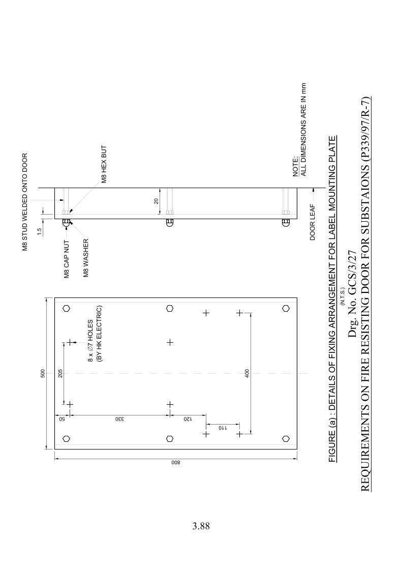
FIG
UR
E (a
) : D
ETAI
LS O
F FI
XIN
G A
RR
ANG
EMEN
T FO
R L
ABEL
MO
UN
TIN
G P
LATE
20
205
50 330 120
800
500
1.5
400
110
8 x
7
HO
LES
(BY
HK
ELEC
TRIC
)
M8
WAS
HER
M8
CAP
NU
T
M8
STU
D W
ELD
ED O
NTO
DO
OR
DO
OR
LEA
F
(N.T
.S.)
M8
HEX
BU
T
Drg
. No.
GC
S/3/
27R
EQU
IREM
ENTS
ON
FIR
E R
ESIS
TIN
G D
OO
R F
OR
SU
BST
AIO
NS
(P33
9/97
/R-7
)
NO
TE:
ALL
DIM
ENSI
ON
S AR
E IN
mm
3.88
3.89
Notes for Drawing No. GCS/3/27 1. Stainless steel referred in this Specification shall mean stainless steel of Grade 316.
2. The Fire Resisting Door (the Door) shall be installed in HK Electric substation only
if it is definitely required FSD of HKSAR Government.
3. The Door shall be type tested to the latest edition of BS 476 for:-
a. A Fire Resistance Period required by FSD; or
b. A Fire Resistance Period of 2 hours,
whichever the Fire Resistance Period is longer. 4. Before substation hand-over, the following documents shall be submitted to the HK
Electric Engineer:- a. A copy of certificate from the manufacturer stating that the Door has complied
with the above tests and all the FSD requirements.
b. A confirmation letter from the developer undertaking the responsibilities for future maintenance of the Door.
5. The Door shall be single swing. The Door shall be of double leaf or single leaf as
specified by HK Electric. For Double Leaf Door, the right hand side leaf shall be opened first when viewed from outside.
6. Unless otherwise specified by HK Electric in the substation layout drawing, clear opening of the Door shall be of:-
a. Height not less than 2600 mm and width not less than 2000 mm for Double
Door.
b. Height not less than 2300 mm and width not less than 920 mm for Single Door.
7. The facing of the Door shall be of stainless steel sheet of thickness not less than
1.5 mm.
3.90
Notes for Drawing No. GCS/3/27
8. Should there be a built-in cylinder lock in the original design of the Door, it shall be
rendered inoperative. A stainless steel lock bar shall be provided and be suitable for HK Electric pad lock with shackle diameter of 14 mm, a clear inside width of 20 mm and inside length of 16 mm. The position of lock bar shall be at 1100 mm to 1500 mm above finished floor level. For Double Door, the lock bar shall be on the right hand side leaf when viewed from outside. Vertical bolts shall be provided for the left hand side leaf to secure in position before closing the right hand side leaf.
9. Automatic door closer, if required by FSD or according to FSD Regulations, shall be
provided for the Door. Should self-closing device be installed on the Door, a substation door security rod as detailed in drawing No. P360/97/R-5 shall be provided.
10. Pull handles of stainless steel shall be provided for Single Door and for both leaves
of Double Door.
11. At least 4 Nos. of hinges each not less than 80 mm long shall be provided at each
door leaf. The hinges shall be so designed such that the Door will open in the direction of egress. Life lubricated hinges shall be provided. The hinges for each leaf of Door must be designed and constructed to withstand the operating weight of the Door plus 50 kgf (assuming at the centre of door leaf) in order to cater for the weight of accessories which HK Electric may install onto the Door.
12. Door stops shall be provided for the closing and the full opening of door leaves.
13. For mounting of HK Electric labels on the Door, a label mounting plate shall be
provided on the external surface of the Door for fixing various labels. The label mounting plate shall be:-
a. of stainless steel sheet not less than 1.5 mm thick with folding edges at the long
side.
b. of dimensions 800 mm high and 500 mm wide at the centre of door leaf at right hand side. Bottom of mounting plate shall be at 1400 mm above ground.
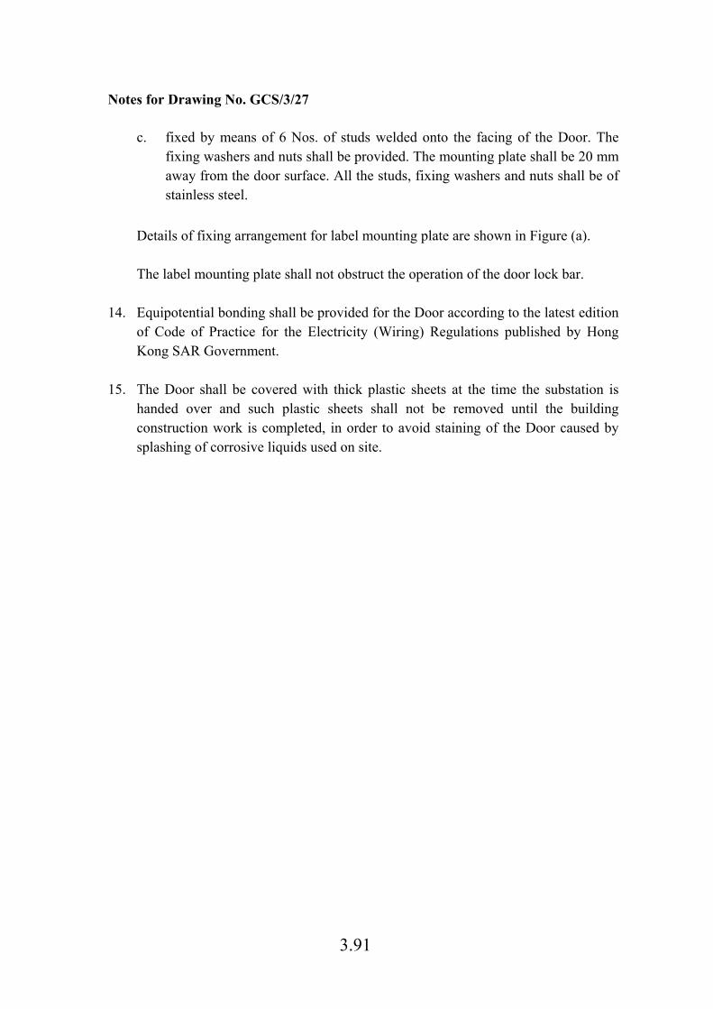
3.91
Notes for Drawing No. GCS/3/27
c. fixed by means of 6 Nos. of studs welded onto the facing of the Door. The fixing washers and nuts shall be provided. The mounting plate shall be 20 mm away from the door surface. All the studs, fixing washers and nuts shall be of stainless steel.
Details of fixing arrangement for label mounting plate are shown in Figure (a). The label mounting plate shall not obstruct the operation of the door lock bar.
14. Equipotential bonding shall be provided for the Door according to the latest edition of Code of Practice for the Electricity (Wiring) Regulations published by Hong Kong SAR Government.
15. The Door shall be covered with thick plastic sheets at the time the substation is
handed over and such plastic sheets shall not be removed until the building construction work is completed, in order to avoid staining of the Door caused by splashing of corrosive liquids used on site.
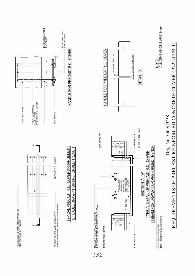
'A'
'A'
TYPI
CAL P
RECA
ST R
.C. C
OVER
ARR
ANGE
MENT
OF C
ABLE
DRA
WPI
T OR
PRE
FORM
ED T
RENC
H
REM
OVA
BLE
I-BEA
M F
OR
SU
PPO
RTI
NG
THE
PREC
AST
R.C
. C
OVE
R
PREC
AST
R.C
. C
OVE
RR
ECES
S AT
SID
E W
ALL
OF
DR
AWPI
TFO
R S
UPP
OR
TIN
G T
HE
REM
OVA
BLE
I-BEA
M
100
125
5
1010
HAND
LE F
OR P
RECA
ST R
.C. C
OVER
200(
L)x4
0(W
)x5
THIC
KSU
S PL
ATE
M10
SU
S N
UT
10 D
IA. S
US
HAN
DLE
FLU
SH W
ITH
PREC
AST
R.C
. C
OVE
R
FILL
ET W
ELD
ING
(ALL
AR
OU
ND
)
13 D
IA.
PVC
TU
BE
MIN. 900
SECT
ION
'A -
'A'
TYPI
CAL D
ETAI
L OF
PREC
AST
R.C.
COV
ER/ I-
BEAM
FOR
DRA
WPI
T OR
PRE
FORM
ED T
RENC
H
1 : 1
00 F
ALL
H
25 D
IA.
DR
AIN
HO
LE
CAB
LE D
UC
TS
SEE
DET
AIL
'G'
CAB
LE D
UC
TS
REC
ESS
AT S
IDE
WAL
L O
F D
RAW
PIT
FOR
SU
PPO
RTI
NG
TH
E R
EMO
VABL
E I-B
EAM
PREC
AST
R.C
. C
OVE
R
REM
OVA
BLE
I-BEA
M F
OR
SUPP
OR
TIN
GTH
E PR
ECAS
TR
.C.
CO
VER
SUS
= ST
AIN
LESS
STE
ELR
.C.
= R
EIN
FOR
CED
CO
NC
RET
E
( OR ASINDICATED INS/S DRAWING)
MIN. 900( OR AS
INDICATED INS/S DRAWING)
100
MIN
.
DETA
IL 'G
'
NO
T M
OR
E TH
AN 1
5 m
m
NO
T M
OR
E TH
AN 6
mm
HAND
LE F
OR P
RECA
ST R
.C. C
OVER
Drg
. No.
GC
S/3/
28R
EQU
IREM
ENTS
OF
PREC
AST
REI
NFO
RC
ED C
ON
CR
ETE
CO
VER
(P72
2/12
/R-1
)
NO
TE:
ALL
DIM
ENSI
ON
S AR
E IN
mm
3.92

3.93
Notes for Drawing No. GCS/3/28 1. Each piece of R.C. cover shall be provided with lifting eyes and shall not weigh
above 80 kgf.
2. The precast R.C. covers shall be numbered in a sequential order by painting numbers of 50 mm high in white colour on both surfaces of each precast R.C. cover. Drawing showing the layout & numbering shall be displayed in substation.
3. Where the R.C. covers are along the route of transportation of substation equipment,
the R.C. covers shall be capable of withstanding an average loading of 20 kPa. Otherwise the R.C. covers shall withstand 10 kPa.
4. Certificate by a registered structural engineer shall be submitted.
5. If H exceeds 1200 mm, SUS CAT ladder in steps of 250 mm shall be provided at a
height 800 mm from bottom of drawpit or trench.
6. After HK Electric cables have been laid, the drawpit or trench shall be backfilled
with sandbags each not exceeding 25 kgf.
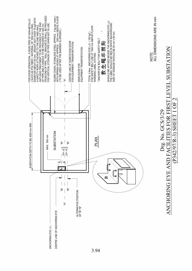
PLA
N
"A
"
"B
""B
"
"A
"
SU
BS
TA
TIO
N
"B
""B
"
MA
IN
D
OO
R F
OR
EQ
UIP
ME
NT
T
RA
NS
PO
RT
AT
IO
N
CE
NT
RE
L
IN
E O
F S
UB
ST
AT
IO
N D
OO
R
FO
R E
QU
IP
ME
NT
T
RA
NS
PO
RT
AT
IO
N
TO
TA
L 4
N
os. A
NC
HO
RIN
G E
YE
( ) ( 1
50
kg
f )
FO
R S
AF
ET
Y B
EL
T U
SE
A
T 1
50
0 m
m A
BO
VE
F
LO
OR
.
WA
RN
IN
G L
AB
EL
S
TA
TIN
G
SH
OU
LD
B
E A
FF
IX
ED
B
ES
ID
E T
HE
A
NC
HO
RIN
G E
YE
( ).
TH
E L
AB
EL
S
HO
UL
D B
E R
ED
IN
W
HIT
E B
AC
KG
RO
UN
D.
SIZ
E O
F S
IG
NA
GE
S
HO
UL
D B
E 5
0 m
m x 8
0 m
m.
" A
NC
HO
R E
YE
B
OL
T F
OR
S
AF
ET
Y B
EL
T
"
GU
AR
D C
HA
IN
( S
TA
IN
LE
SS
S
TE
EL
A
PP
RO
X. 3
kg
p
er m
etre
)
WIT
H S
PR
IN
G H
OO
KS
A
T A
PP
RO
X. 1
20
0 m
m A
BO
VE
F
LO
OR
( T
O B
E U
SE
D A
FT
ER
T
HE
B
AR
RIE
R IS
O
PE
NE
D )
FO
R D
OO
R O
PE
RA
TIO
N, A
R
IG
ID
P
IP
E O
F N
ON
-M
ET
AL
LIC
( S
UC
H A
S P
OL
YM
ER
) M
AT
ER
IA
L O
F 1
60
0 m
m L
ON
G,
DIA
ME
TE
R A
BO
UT
6
0 m
m, W
EIG
HT
N
OT
O
VE
R 1
0 kg
f W
IT
H
A S
AF
ET
Y R
OP
E A
TT
AC
HE
D T
O T
HE
E
ND
A
ND
W
AL
L.
AN
TI-S
KID
T
RE
AT
ME
NT
T
O B
E P
RO
VID
ED
A
T T
HE
E
ND
OF
P
IP
E A
ND
A
H
AN
DL
E T
O B
E P
RO
VID
ED
A
T 4
00
m
m
FR
OM
E
ND
O
F P
IP
E. W
AL
L B
RA
CK
ET
S S
HA
LL
B
E P
RO
VID
ED
FO
R V
ER
TIC
AL
S
TO
RA
GE
O
F P
IP
E W
HE
N N
OT
IN
U
SE
.
J
J
CE
NT
RE
L
IN
E O
F A
NC
HO
RIN
G E
YE
AN
CH
OR
IN
G E
YE
( )
I
OF
"B
"-"B
"
AL
TE
RN
AT
IV
E P
OS
IT
IO
N
SU
BS
TA
TIO
N D
EP
TH
T
O B
E 4
00
0 m
m M
IN
.
MA
X. 2
00
MA
X. 2
00
MA
X. 5
00
m
m
Drg
. No.
GC
S/3/
29A
NC
HO
RIN
G E
YE
AN
D F
AC
ILIT
IES
FOR
FIR
ST L
EVEL
SU
BST
ATI
ON
(P34
2/97
/R-3
) SH
EET
1 O
F 2
NO
TE
:
AL
L D
IM
EN
SIO
NS
A
RE
IN
m
m
3.94
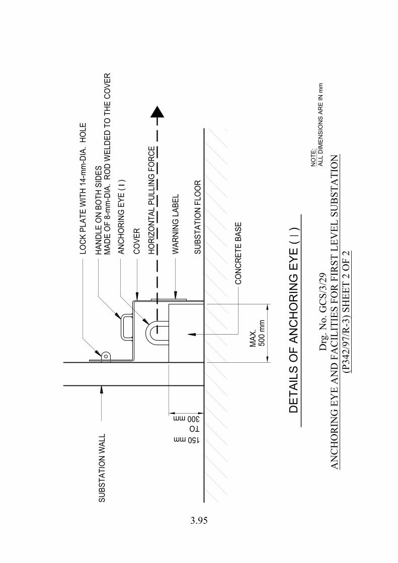
COVE
R
500
mm
300 mm
LOCK
PLA
TE W
ITH
14-m
m-D
IA.
HOLE
HAND
LE O
N BO
TH S
IDES
MAD
E O
F 8-
mm
-DIA
. RO
D W
ELDE
D TO
THE
CO
VER
ANCH
ORI
NG E
YE (
)
DET
AILS
OF
ANC
HO
RIN
G E
YE (
)
I
SUBS
TATI
ON
WAL
L
MAX
.
CONC
RETE
BAS
E
SUBS
TATI
ON
FLO
OR
WAR
NING
LAB
EL
HORI
ZONT
AL P
ULLI
NG F
ORC
E
150 mmTO
Drg
. No.
GC
S/3/
29A
NC
HO
RIN
G E
YE
AN
D F
AC
ILIT
IES
FOR
FIR
ST L
EVEL
SU
BST
ATI
ON
(P34
2/97
/R-3
) SH
EET
2 O
F 2
NO
TE:
ALL
DIM
ENSI
ON
S AR
E IN
mm
3.95
3.96
Notes for Drawing No. GCS/3/29 1. The anchoring eye (I) will be used for transportation of equipment to and from the
substation. A horizontal pulling force in direction along the centre line “A” – “A” will be applied to the anchoring eye (I). The anchoring eye (I) shall be suitable for a “SAFE WORKING LOAD” of 1000 kgf for such application, however the “TESTING LOAD” shall be 2000 kgf.
2. A certificate from a registered professional engineer in accordance with the factories
and industrial undertakings ordinance shall be submitted to HK Electric certifying the above “TESTING LOAD” of anchoring eye (I) and the 150-kgf working load of anchoring eye (J).
3. All anchoring eyes shall be made of stainless steel, hot dip galvanised steel or steel
with suitable anti-corrosion treatment. A concrete base shall be provided for the anchoring eye (I) to minimize corrosion to the eye due to lodgement of water on floor.
4. A cover with handle (covering the front, the top and the 2 sides) made of stainless
steel or hot dip galvanised steel shall be provided to prevent the improper use of the anchoring eye (I). An engraved warning label stating:
“S.W.L. 1000 kgf DO NOT USE THE ANCHORING EYE BEFORE PROPER
TEST 未經測試不可使用”
shall be bolted on the front of cover. The lettering shall be approximately 15 mm high. A locking plate shall be provided on wall to lock the cover in position. The locking plate shall be suitable for padlocks with an 8 mm diameter shackle and a clear inside width of 20 mm and inside length of 16 mm.
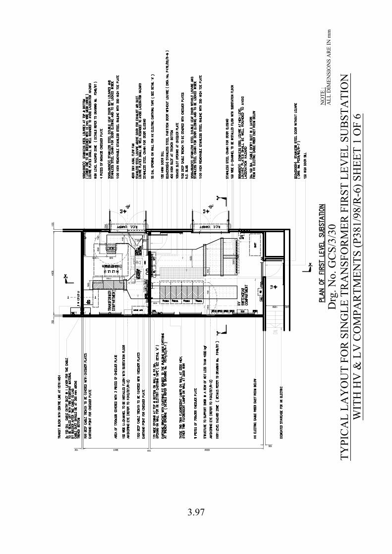
Drg
. No.
GC
S/3/
30TY
PIC
AL
LAY
OU
T FO
R S
ING
LE T
RA
NSF
OR
MER
FIR
ST L
EVEL
SU
BST
ATI
ON
WIT
H H
V &
LV
CO
MPA
RTM
ENTS
(P38
1/98
/R-6
) SH
EET
1 O
F 6
NO
TE :
ALL
DIM
ENSI
ON
S A
RE
IN m
m
3.97
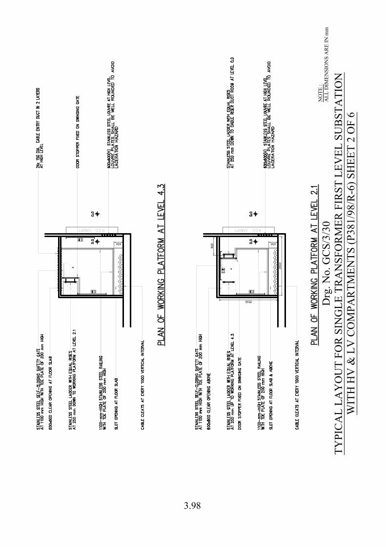
Drg
. No.
GC
S/3/
30TY
PIC
AL
LAY
OU
T FO
R S
ING
LE T
RA
NSF
OR
MER
FIR
ST L
EVEL
SU
BST
ATI
ON
WIT
H H
V &
LV
CO
MPA
RTM
ENTS
(P38
1/98
/R-6
) SH
EET
2 O
F 6
NO
TE :
ALL
DIM
ENSI
ON
S A
RE
IN m
m
3.98
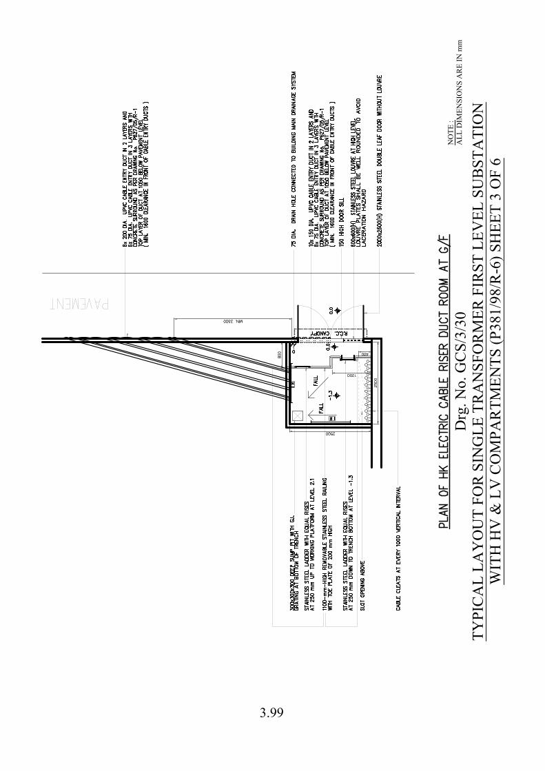
Drg
. No.
GC
S/3/
30TY
PIC
AL
LAY
OU
T FO
R S
ING
LE T
RA
NSF
OR
MER
FIR
ST L
EVEL
SU
BST
ATI
ON
WIT
H H
V &
LV
CO
MPA
RTM
ENTS
(P38
1/98
/R-6
) SH
EET
3 O
F 6
NO
TE :
ALL
DIM
ENSI
ON
S A
RE
IN m
m
3.99
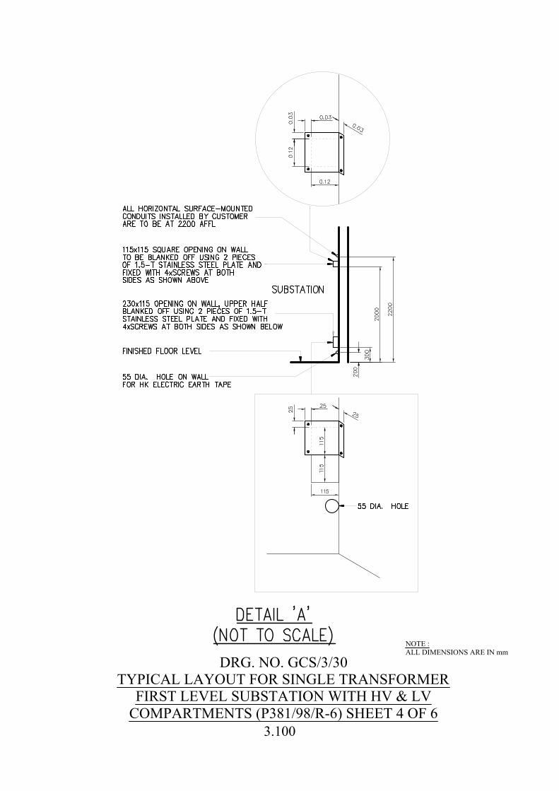
DRG. NO. GCS/3/30TYPICAL LAYOUT FOR SINGLE TRANSFORMER
FIRST LEVEL SUBSTATION WITH HV & LVCOMPARTMENTS (P381/98/R-6) SHEET 4 OF 6
NOTE :ALL DIMENSIONS ARE IN mm
3.100
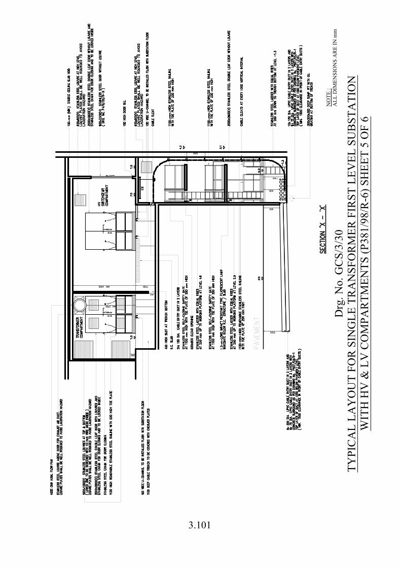
Drg
. No.
GC
S/3/
30TY
PIC
AL
LAY
OU
T FO
R S
ING
LE T
RA
NSF
OR
MER
FIR
ST L
EVEL
SU
BST
ATI
ON
WIT
H H
V &
LV
CO
MPA
RTM
ENTS
(P38
1/98
/R-6
) SH
EET
5 O
F 6
NO
TE :
ALL
DIM
ENSI
ON
S A
RE
IN m
m
3.101

Drg
. No.
GC
S/3/
30TY
PIC
AL
LAY
OU
T FO
R S
ING
LE T
RA
NSF
OR
MER
FIR
ST L
EVEL
SU
BST
ATI
ON
WIT
H H
V &
LV
CO
MPA
RTM
ENTS
(P38
1/98
/R-6
) SH
EET
6 O
F 6
NO
TE :
ALL
DIM
ENSI
ON
S A
RE
IN m
m
3.102
3.103
Notes for Drawing No. GCS/3/30 1. Level of G/F is assumed at + 0.0, levels of working platforms are with reference to
the high level of G/F.
2. Direct vehicular access shall be available to the front of substation door at a horizontal distance not exceeding 4 m. Direct vehicular access shall mean accessibility of a standard 30 ton fire appliance of FSD of HKSAR Government.
3. The substation floor level must not be of 7 m higher than the pavement level measured at centre line of substation door.
4. The gradient of access road to substation (when measured along +/-10 m
horizontally from centre line of door ‘A’) must not be greater than 1:12.
5. There shall not be any protruded objects obstructing transportation of equipment to /
from substation when measured along +/-6 m horizontally from the centre line of door ‘A’ and vertically from 3m of top of door ‘A’ down to pavement level.
6. The separation of the two cable entry points shall be not less than 3500 mm.
7. The developer / landlord shall provide haulage lug(s) inside the cable riser duct as
and required by HK Electric for cable laying woks. The statutory loading tests of the haulage lug(s), when required, shall be arranged by the developer / landlord. These haulage lug(s) shall be of removable type such that it (they) could be removed after completion of cable laying.
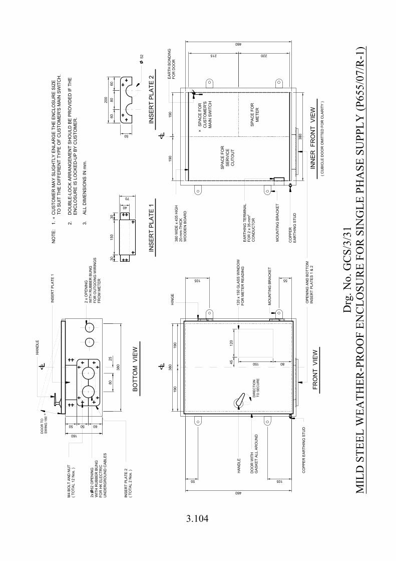
DO
OR
W
IT
H
GA
SK
ET
A
LL
A
RO
UN
D
12
0 x 1
50
G
LA
SS
W
IN
DO
W
FO
R M
ET
ER
R
EA
DIN
G
150
12
0
FR
ON
T V
IE
W
DIR
EC
TIO
N
TO
S
EC
UR
E
HA
ND
LE
BO
TT
OM
V
IE
W
38
0
2x 5
2 O
PE
NIN
G
WIT
H R
UB
BE
R B
UN
G
FO
R H
K E
LE
CT
RIC
UN
DE
RG
RO
UN
D C
AB
LE
S
HA
ND
LE
160
105
HIN
GE
215 220
EA
RT
HIN
G T
ER
MIN
AL
FO
R 2
x 3
5-m
m
CO
ND
UC
TO
R
2
IN
NE
R F
RO
NT
V
IE
W
MO
UN
TIN
G B
RA
CK
ET
38
0 W
ID
E x 4
35
H
IG
H
20
-m
m-T
HIC
K
WO
OD
EN
B
OA
RD
SP
AC
E F
OR
SE
RV
IC
E
CU
TO
UT
SP
AC
E F
OR
CU
ST
OM
ER
'S
MA
IN
S
WIT
CH
SP
AC
E F
OR
ME
TE
R
DO
OR
T
O
SW
IN
G 180
MO
UN
TIN
G B
RA
CK
ET
( C
UB
IC
LE
D
OO
R O
MIT
TE
D F
OR
C
LA
RIT
Y )
2 x O
PE
NIN
G
WIT
H R
UB
BE
R B
UN
G
FO
R O
UT
GO
IN
G W
IR
IN
GS
FR
OM
M
ET
ER
NO
TE
:1.
2.
CU
ST
OM
ER
M
AY
S
LIG
HT
LY
E
NLA
RG
E T
HE
E
NC
LO
SU
RE
S
IZ
E
TO
S
UIT
T
HE
D
IF
FE
RE
NT
T
YP
E O
F C
US
TO
ME
R'S
M
AIN
S
WIT
CH
.
DO
UB
LE
-LO
CK
A
RR
AN
GE
ME
NT
S
HO
ULD
B
E P
RO
VID
ED
IF
T
HE
EN
CLO
SU
RE
IS
LO
CK
ED
-U
P B
Y C
US
TO
ME
R.
460
460
55
80
60
M4
B
OL
T A
ND
N
UT
( T
OT
AL
1
2 N
os. )
IN
SE
RT
P
LA
TE
1
IN
SE
RT
P
LA
TE
2
( T
OT
AL
2
N
os. )
80
IN
SE
RT
P
LA
TE
1
IN
SE
RT
P
LA
TE
2
38
0
52
60
20
0
50
15
03
03
0
70
40
55105
c
L
25
c
L
CO
PP
ER
E
AR
TH
IN
G S
TU
D
OP
EN
IN
G A
ND
B
OT
TO
M
IN
SE
RT
P
LA
TE
S 1
&
2
c
L
19
0
19
0
38
0
CO
PP
ER
EA
RT
HIN
G S
TU
D
EA
RT
H B
ON
DIN
G
FO
R D
OO
R
45
5050
80
60
19
0
19
0
3.
ALL D
IM
EN
SIO
NS
IN
m
m.
Drg
. No.
GC
S/3/
31M
ILD
STE
EL W
EATH
ER-P
RO
OF
ENC
LOSU
RE
FOR
SIN
GLE
PH
ASE
SU
PPLY
(P65
5/07
/R-1
)
3.104
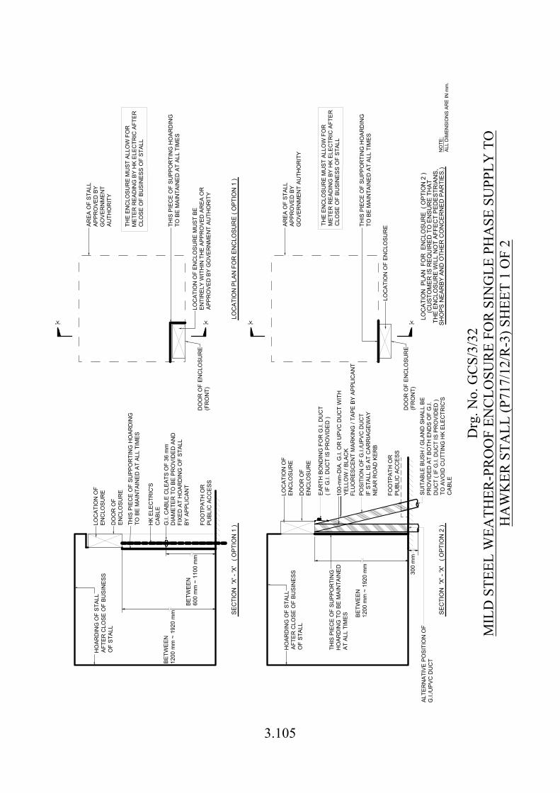
NO
TE:
ALL
DIM
ENSI
ON
S AR
E IN
mm
.
LOC
ATIO
N O
FEN
CLO
SUR
EH
OAR
DIN
G O
F ST
ALL
AFTE
R C
LOSE
OF
BUSI
NES
SO
F ST
ALL
HK
ELEC
TRIC
'SC
ABLE
FOO
TPAT
H O
RPU
BLIC
AC
CES
S
THIS
PIE
CE
OF
SUPP
OR
TIN
G H
OAR
DIN
GTO
BE
MAI
NTA
INED
AT
ALL
TIM
ES
DO
OR
OF
ENC
LOSU
RE
(FR
ON
T)
DO
OR
OF
ENC
LOSU
RE
HO
ARD
ING
OF
STAL
LAF
TER
CLO
SE O
F BU
SIN
ESS
OF
STAL
L
THIS
PIE
CE
OF
SUPP
OR
TIN
GH
OAR
DIN
G T
O B
E M
AIN
TAIN
EDAT
ALL
TIM
ES
LOC
ATIO
N O
FEN
CLO
SUR
E
DO
OR
OF
ENC
LOSU
RE
FOO
TPAT
H O
RPU
BLIC
AC
CES
S
AREA
OF
STAL
LAP
PRO
VED
BY
GO
VER
NM
ENT
AUTH
OR
ITY
THIS
PIE
CE
OF
SUPP
OR
TIN
G H
OAR
DIN
GTO
BE
MAI
NTA
INED
AT
ALL
TIM
ES
LOC
ATIO
N O
F EN
CLO
SUR
E
DO
OR
OF
ENC
LOSU
RE
(FR
ON
T)
SEC
TIO
N '
X' -
'X'
( O
PTIO
N 1
)
AREA
OF
STAL
LAP
PRO
VED
BY
GO
VER
NM
ENT
AUTH
OR
ITY
'X''X' 'X''X'
300
mm
LOC
ATIO
N P
LAN
FO
R E
NC
LOSU
RE
( O
PTIO
N 2
)(C
UST
OM
ER IS
REQ
UIR
ED T
O E
NSU
RE
THAT
THE
ENC
LOSU
RE
WIL
L N
OT
AFFE
CT
PED
ESTR
IAN
S,SH
OPS
NEA
RBY
AN
D O
THER
CO
NC
ERN
ED P
ARTI
ES.)
THIS
PIE
CE
OF
SUPP
OR
TIN
G H
OAR
DIN
GTO
BE
MAI
NTA
INED
AT
ALL
TIM
ES
SEC
TIO
N '
X' -
'X'
( O
PTIO
N 2
)
THE
ENC
LOSU
RE
MU
ST A
LLO
W F
OR
MET
ER R
EAD
ING
BY
HK
ELEC
TRIC
AFT
ERC
LOSE
OF
BUSI
NES
S O
F ST
ALL
LOC
ATIO
N O
F EN
CLO
SUR
E M
UST
BE
ENTI
REL
Y W
ITH
IN T
HE
APPR
OVE
D A
REA
OR
APPR
OVE
D B
Y G
OVE
RN
MEN
T AU
THO
RIT
Y
LOC
ATIO
N P
LAN
FO
R E
NC
LOSU
RE
( OPT
ION
1 )
THE
ENC
LOSU
RE
MU
ST A
LLO
W F
OR
MET
ER R
EAD
ING
BY
HK
ELEC
TRIC
AFT
ERC
LOSE
OF
BUSI
NES
S O
F ST
ALL
G.I.
CAB
LE C
LEAT
S O
F 36
mm
DIA
MET
ER T
O B
E PR
OVI
DED
AN
DFI
XED
AT
HO
ARD
ING
OF
STAL
LBY
APP
LIC
ANT
BETW
EEN
1200
mm
~ 1
920
mm BE
TWEE
N12
00 m
m ~
192
0 m
m
BETW
EEN
600
mm
~ 1
100
mm
EAR
TH B
ON
DIN
G F
OR
G.I.
DU
CT
( IF
G.I.
DU
CT
IS P
RO
VID
ED )
POSI
TIO
N O
F G
.I./U
PVC
DU
CT
IF S
TALL
IS A
T C
ARR
IAG
EWAY
NEA
R R
OAD
KER
B
SUIT
ABLE
BU
SH /
GLA
ND
SH
ALL
BEPR
OVI
DED
AT
BOTH
EN
DS
OF
G.I.
DU
CT
( IF
G.I.
DU
CT
IS P
RO
VID
ED )
TO A
VOID
CU
TTIN
G H
K EL
ECTR
IC'S
CAB
LE
ALTE
RN
ATIV
E PO
SITI
ON
OF
G.I.
/UPV
C D
UC
T
100-
mm
-DIA
. G.I.
OR
UPV
C D
UC
T W
ITH
YELL
OW
/ BL
ACK
FLU
OR
ESC
ENT
MAR
KIN
G /
TAPE
BY
APPL
ICAN
T
Drg
. No.
GC
S/3/
32M
ILD
STE
EL W
EATH
ER-P
RO
OF
ENC
LOSU
RE
FOR
SIN
GLE
PH
ASE
SU
PPLY
TO
HA
WK
ER S
TALL
(P71
7/12
/R-3
) SH
EET
1 O
F 2
3.105
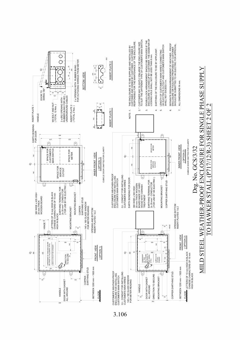
CU
STO
MER
'S W
EATH
ER-P
RO
OF
ENC
LOSU
RE
FOR
INST
ALLI
NG
CU
STO
MER
'S M
AIN
SW
ITC
H
HAN
DLE
DO
OR
WIT
H G
ASKE
TAL
L AR
OU
ND
CO
PPER
EAR
THIN
G S
TUD
DIR
ECTI
ON
TO S
ECU
RE
HIN
GE
MO
UN
TIN
G B
RAC
KET
CO
PPER
EAR
THIN
G S
TUD
SPAC
E FO
RSE
RVI
CE
CU
TOU
T
SPAC
E FO
RM
ETER
EAR
TH B
ON
DIN
GFO
R D
OO
RH
AND
LE
CU
STO
MER
'S W
EATH
ER-P
RO
OF
ENC
LOSU
RE
FOR
INST
ALLI
NG
CU
STO
MER
'S M
AIN
SW
ITC
H
140
x 18
0 G
LASS
WIN
DO
WFO
R M
ETER
REA
DIN
G
MO
UN
TIN
G B
RAC
KET
CO
PPER
EAR
THIN
G S
TUD
HIN
GE
EAR
TH B
ON
DIN
G F
OR
DO
OR
MO
UN
TIN
G B
RAC
KET
CO
PPER
EAR
THIN
G S
TUD
SPAC
E FO
RSE
RVI
CE
CU
TOU
T
SPAC
E FO
RM
ETER
FRO
NT
VIE
W
( OPT
ION
1)
( OPT
ION
1)
INN
ER F
RO
NT
VIE
W
BOTT
OM
VIE
W
FRO
NT
VIE
W
( OPT
ION
2)
INN
ER F
RO
NT
VIE
W
( OPT
ION
2)
INSE
RT
PLAT
E 1
INSE
RT
PLAT
E 2
8025
3030
DO
OR
WIT
H G
ASKE
TAL
L AR
OU
ND
215
105
55
380
55
460
105
460
190
380
380
55
55
5555
330
190
380
85
55
150
200
60
50
Ø52
FLO
OR
140
x 18
0 G
LASS
WIN
DO
WFO
R M
ETER
REA
DIN
G
DO
OR
TO
SWIN
G 1
80°
BETW
EEN
120
0 m
m ~
192
0 m
m
FLO
OR
2 x
Ø52
OPE
NIN
G W
ITH
RU
BBER
BU
NG
FO
R H
ECU
ND
ERG
RO
UN
D C
ABLE
S
BETW
EEN
120
0 m
m ~
192
0 m
m
MO
UN
TIN
G B
RAC
KET
OPE
NIN
G A
ND
BO
TTO
MIN
SER
T PL
ATES
1 &
2
380
WID
E x
435
HIG
H20
-mm
-TH
ICK
WO
OD
EN B
OAR
D
* SP
ACE
FOR
CU
STO
MER
'SM
AIN
SW
ITC
HM
4 BO
LT A
ND
NU
T( T
OTA
L 12
Nos
. )
CU
BIC
LE D
OO
R O
MIT
TED
FO
R C
LAR
ITY
OPE
NIN
G A
ND
BO
TTO
MIN
SER
T PL
ATES
1 &
2EAR
THIN
G T
ERM
INAL
FO
R2x
35-
mm
² C
ON
DU
CTO
R( F
OR
USE
BY
HK
ELEC
TRIC
)
CU
BIC
LE D
OO
R O
MIT
TED
FO
R C
LAR
ITY
INSE
RT
PLAT
E 1
G.I.
CO
ND
UIT
FO
R IN
STAL
LIN
GC
UST
OM
ER'S
MAI
N W
IRES
G.I.
CO
ND
UIT
FO
R IN
STAL
LIN
GC
UST
OM
ER'S
MAI
N W
IRES
EAR
THIN
G T
ERM
INAL
FO
R2x
35-
mm
² C
ON
DU
CTO
R( F
OR
USE
BY
HK
ELEC
TRIC
)
60
300
125
200
280
125
20
LETT
ERS
OF
10 m
m H
IGH
IN B
LAC
KC
HIN
ESE
CH
ARAC
TER
S O
F 15
mm
HIG
H IN
BLA
CK
LETT
ERS
OF
10 m
m H
IGH
IN B
LAC
KC
HIN
ESE
CH
ARAC
TER
S O
F 15
mm
HIG
H IN
BLA
CK
140
25
180 65
HAN
DLE
25
140
180 65
DIR
ECTI
ON
TO
SEC
UR
E
380
175
INSE
RT
PLAT
E 2
( TO
TAL
2 N
os. )
2 x
OPE
NIN
G W
ITH
RU
BBER
BU
NG
FOR
OU
TGO
ING
WIR
ING
S FR
OM
MET
ER
OW
NER
SHIP
OF
THIS
EN
CLO
SUR
EBE
LON
GS
TO T
HE
USE
RS,
STA
LL: :
OW
NER
SHIP
OF
THIS
ENC
LOSU
RE
BELO
NG
S TO
THE
USE
RS,
STAL
L: :
380
WID
E x
300
HIG
H20
-mm
-TH
ICK
WO
OD
ENBO
ARD
MAD
E O
F H
ARD
WO
OD
WIT
H V
ARN
ISH
TREA
TMEN
T
220
190
190
8060
5065
NO
TE :
1.TH
E EN
CLO
SUR
E IS
TO
BE
SUPP
LIED
AN
D IN
STAL
LED
BY
CU
STO
MER
AN
D O
WN
ED B
Y C
UST
OM
ER.
CU
STO
MER
ISR
ESPO
NSI
BLE
FOR
TH
E M
AIN
TEN
ANC
E O
F TH
E EN
CLO
SUR
E.
2. *
CU
STO
MER
MAY
SLI
GH
TLY
ENLA
RG
E TH
E EN
CLO
SUR
E SI
ZETO
SU
IT T
HE
DIF
FER
ENT
TYPE
OF
CU
STO
MER
'S M
AIN
SW
ITC
H.
3.
DO
UBL
E-LO
CK
ARR
ANG
EMEN
T SH
OU
LD B
E PR
OVI
DED
IF T
HE
EN
CLO
SUR
E IS
LO
CKE
D-U
P BY
CU
STO
MER
. TH
E D
IAM
ETER
OF
LO
CKI
NG
HO
LE S
HAL
L N
OT
BE L
ESS
THAN
8 m
m.
4.
EAR
THIN
G O
F TH
E EN
CLO
SUR
E TO
BE
BY A
PPLI
CAN
T.
5.
LEN
GTH
OF
CU
STO
MER
'S M
AIN
WIR
ES C
ON
NEC
TIN
G
H
K EL
ECTR
IC'S
CU
TOU
T AN
D C
UST
OM
ER'S
MAI
N S
WIT
CH
SH
ALL
NO
T EX
CEE
D 3
m.
6.
SEP
ARAT
E D
ESIG
N/A
RR
ANG
EMEN
T O
F W
EATH
ER -
PRO
OF
EN
CLO
SUR
E O
R F
ACIL
ITIE
S PR
OPO
SED
BY
CU
STO
MER
SH
OU
LD B
E SU
BMIT
TED
TO
HK
ELEC
TRIC
FO
R A
PPR
OVA
L.
7.
ALL
DIM
ENSI
ON
S IN
mm
.
Drg
. No.
GC
S/3/
32M
ILD
STE
EL W
EATH
ER-P
RO
OF
ENC
LOSU
RE
FOR
SIN
GLE
PH
ASE
SU
PPLY
TO H
AW
KER
STA
LL (P
717/
12/R
-3) S
HEE
T 2
OF
2
3.106


![T921 Toilet Cubicle User Manual - Shades Technics · shades technics [T921 TOILET CUBICLE USER MANUAL] 3 Cubicle Operating Instructions Switching the cubicle ‘ON’ Engage the WC](https://static.fdocuments.us/doc/165x107/5d28d82d88c9934b068c87aa/t921-toilet-cubicle-user-manual-shades-shades-technics-t921-toilet-cubicle.jpg)