Chapter 3 DesignDesign Files geopakdtmv14.dgn Standard seed file for creating 3d files for Design...
73
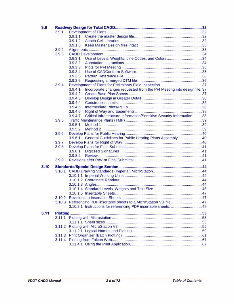
VDOT CADD Manual 3-ii of 72 Table of Contents Chapter 3 - Plan Design TABLE OF CONTENTS CHAPTER 3.................................................................................................................................................. 3 3.1 Plan File Creation ............................................................................................................. 3 3.1.1 File names.............................................................................................................. 3 3.1.2 Design File Sheet Numbering ................................................................................ 4 3.1.3 Seed Files .............................................................................................................. 6 3.1.3.1 New MicroStation Seed Files ................................................................. 7 3.1.3.2 Unchanged MicroStation Seed Files ...................................................... 7 3.1.3.3 Operating Parameters ............................................................................ 9 3.2 Title Sheet........................................................................................................................ 10 3.2.1 Create a new file in Falcon .................................................................................. 10 3.2.1.1 Select appropriate Seed file ................................................................. 10 3.2.1.2 Create alignment and sheet layout in the center of the title sheet. ...... 10 3.2.1.3 Complete Title Sheet ............................................................................ 11 3.2.1.4 All text sizes .......................................................................................... 11 3.2.1.5 Sample Title Sheets.............................................................................. 12 3.2.1.6 Critical Infrastructure Information ......................................................... 13 3.2.1.7 Digital Signatures .................................................................................. 13 3.3 Location Map................................................................................................................... 14 3.3.1 Create a Location Map Sheet. ............................................................................. 14 3.3.2 Find Location Maps .............................................................................................. 15 3.3.2.1 Reference appropriate county map to design file ................................. 18 3.3.3 County Map DGN Files ........................................................................................ 18 3.4 Index of Sheets ............................................................................................................... 21 3.5 General Notes ................................................................................................................. 22 3.5.1 Create a new General Notes Sheet ..................................................................... 22 3.5.1.1 Create a new file in Falcon ................................................................... 22 3.5.1.2 Access the general note macro ............................................................ 22 3.5.1.3 Instructions for Labeling General Notes Plan Sheet using macro ........ 22 3.5.1.4 Access the general note cell library ...................................................... 23 3.5.1.5 Contents of General Notes Sheet ......................................................... 24 3.5.1.6 Add any special or non-standard notes ................................................ 24 3.5.1.7 Complete the sheet title block .............................................................. 24 3.6 Cross Section Labeling.................................................................................................. 26 3.6.1 Instructions for Labeling Cross Section Plan Sheets ........................................... 26 3.6.2 Examples of Cross Section Labeling ................................................................... 27 3.7 Macros ............................................................................................................................. 28 3.7.1 VDOT Macros ...................................................................................................... 28 3.8 Roadway Typical Sections ............................................................................................ 29 3.8.1 Changes Allowed in Typical Sections .................................................................. 29 3.8.2 Typical Section Sheet in Falcon........................................................................... 29 3.8.2.1 Create a new file ................................................................................... 29 3.8.2.2 Fill in all pertinent information ............................................................... 29 3.8.2.3 Place appropriate cell(s) ....................................................................... 29 3.8.2.4 Examples of Typical Section Sheet ...................................................... 30
Transcript of Chapter 3 DesignDesign Files geopakdtmv14.dgn Standard seed file for creating 3d files for Design...

VDOT CADD Manual
3-ii of 72
Table of Contents
Chapter 3 - Plan Design TABLE OF CONTENTS CHAPTER 3 .................................................................................................................................................. 3
3.1 Plan File Creation ............................................................................................................. 3 3.1.1 File names .............................................................................................................. 3 3.1.2 Design File Sheet Numbering ................................................................................ 4 3.1.3 Seed Files .............................................................................................................. 6
3.1.3.1 New MicroStation Seed Files ................................................................. 7 3.1.3.2 Unchanged MicroStation Seed Files ...................................................... 7 3.1.3.3 Operating Parameters ............................................................................ 9
3.2 Title Sheet ........................................................................................................................ 10 3.2.1 Create a new file in Falcon .................................................................................. 10
3.2.1.1 Select appropriate Seed file ................................................................. 10 3.2.1.2 Create alignment and sheet layout in the center of the title sheet. ...... 10 3.2.1.3 Complete Title Sheet ............................................................................ 11 3.2.1.4 All text sizes .......................................................................................... 11 3.2.1.5 Sample Title Sheets .............................................................................. 12 3.2.1.6 Critical Infrastructure Information ......................................................... 13 3.2.1.7 Digital Signatures .................................................................................. 13
3.3 Location Map ................................................................................................................... 14 3.3.1 Create a Location Map Sheet. ............................................................................. 14 3.3.2 Find Location Maps .............................................................................................. 15
3.3.2.1 Reference appropriate county map to design file ................................. 18 3.3.3 County Map DGN Files ........................................................................................ 18
3.4 Index of Sheets ............................................................................................................... 21
3.5 General Notes ................................................................................................................. 22 3.5.1 Create a new General Notes Sheet ..................................................................... 22
3.5.1.1 Create a new file in Falcon ................................................................... 22 3.5.1.2 Access the general note macro ............................................................ 22 3.5.1.3 Instructions for Labeling General Notes Plan Sheet using macro ........ 22 3.5.1.4 Access the general note cell library ...................................................... 23 3.5.1.5 Contents of General Notes Sheet ......................................................... 24 3.5.1.6 Add any special or non-standard notes ................................................ 24 3.5.1.7 Complete the sheet title block .............................................................. 24
3.6 Cross Section Labeling .................................................................................................. 26 3.6.1 Instructions for Labeling Cross Section Plan Sheets ........................................... 26 3.6.2 Examples of Cross Section Labeling ................................................................... 27
3.7 Macros ............................................................................................................................. 28 3.7.1 VDOT Macros ...................................................................................................... 28
3.8 Roadway Typical Sections ............................................................................................ 29 3.8.1 Changes Allowed in Typical Sections .................................................................. 29 3.8.2 Typical Section Sheet in Falcon ........................................................................... 29
3.8.2.1 Create a new file ................................................................................... 29 3.8.2.2 Fill in all pertinent information ............................................................... 29 3.8.2.3 Place appropriate cell(s) ....................................................................... 29 3.8.2.4 Examples of Typical Section Sheet ...................................................... 30
VDOT CADD Manual
3-ii of 72
Table of Contents
3.9 Roadway Design for Total CADD .................................................................................. 32 3.9.1 Development of Plans .......................................................................................... 32
3.9.1.1 Create the master design file ................................................................ 32 3.9.1.2 Attach Cell Libraries .............................................................................. 32 3.9.1.3 Keep Master Design files intact ............................................................ 33
3.9.2 Alignments ........................................................................................................... 33 3.9.3 CADD Development ............................................................................................. 34
3.9.3.1 Use of Levels, Weights, Line Codes, and Colors ................................. 34 3.9.3.2 Annotation Instructions ......................................................................... 34 3.9.3.3 Plots for PFI Meeting ............................................................................ 35 3.9.3.4 Use of CADConform Software .............................................................. 35 3.9.3.5 Pattern Reference File .......................................................................... 36 3.9.3.6 Requesting a merged DTM file ............................................................. 36
3.9.4 Development of Plans for Preliminary Field Inspection ....................................... 37 3.9.4.1 Incorporate changes requested from the PFI Meeting into design file. 37 3.9.4.2 Create Base Plan Sheets ..................................................................... 37 3.9.4.3 Develop Design in Greater Detail ......................................................... 38 3.9.4.4 Construction Limits ............................................................................... 38 3.9.4.5 Intermediate Prints/PDFs...................................................................... 38 3.9.4.6 Right of Way and Easements ............................................................... 38 3.9.4.7 Critical Infrastructure Information/Sensitive Security Information ........ 38
3.9.5 Traffic Maintenance Plans (TMP) ........................................................................ 39 3.9.5.1 Method 1 ............................................................................................... 39 3.9.5.2 Method 2 ............................................................................................... 39
3.9.6 Develop Plans for Public Hearing ........................................................................ 40 3.9.6.1 General Guidelines for Public Hearing Plans Assembly ...................... 40
3.9.7 Develop Plans for Right of Way ........................................................................... 40 3.9.8 Develop Plans for Final Submittal ........................................................................ 41
3.9.8.1 Digitized Signatures .............................................................................. 41 3.9.8.2 Review .................................................................................................. 41
3.9.9 Revisions after R/W or Final Submittal ................................................................ 41
3.10 Standards/Special Design Section .............................................................................. 44 3.10.1 CADD Drawing Standards (Imperial) MicroStation .............................................. 44
3.10.1.1 Imperial Working Units .......................................................................... 44 3.10.1.2 Coordinate Readout .............................................................................. 44 3.10.1.3 Angles ................................................................................................... 44 3.10.1.4 Standard Levels, Weights and Text Size .............................................. 45 3.10.1.5 Insertable Sheets .................................................................................. 47
3.10.2 Revisions to Insertable Sheets ............................................................................ 47 3.10.3 Referencing PDF insertable sheets to a MicroStation V8i file ............................. 47
3.10.3.1 Instructions for referencing PDF insertable sheets: ............................. 48
3.11 Plotting ............................................................................................................................. 53 3.11.1 Plotting with Microstation ..................................................................................... 53
3.11.1.1 Sheet sizes ........................................................................................... 53 3.11.2 Plotting with MicroStation V8i .............................................................................. 55
3.11.2.1 Logical Names and Plotting .................................................................. 59 3.11.3 Print Organizer (Batch Plotting) ........................................................................... 61 3.11.4 Plotting from Falcon Web ..................................................................................... 67
3.11.4.1 Using the Print Application.................................................................... 67

VDOT CADD Manual
3-iii of 72
Table of Contents
Tables and Figures Table 3-1 File Naming Conventions ....................................................................................... 3 Table 3-2 Sheet Numbering Conventions ............................................................................... 5 Table 3-3 New Seed Files ...................................................................................................... 7 Table 3-4 Seed Files .............................................................................................................. 7 Figure 3-5 Imperial Title sheet ................................................................................................12 Figure 3-6 Metric Title sheet ...................................................................................................12 Figure 3-7 General Notes sheet .............................................................................................25 Figure 3-8 Imperial Typical Section Sheet ..............................................................................30 Figure 3-9 Metric Typical Section Sheet .................................................................................31 Figure 3-10 Sheet Plotting Scales ............................................................................................54
VDOT CADD Manual
3-3 of 72 Plan File Creation
Chapter 3 3.1 Plan File Creation
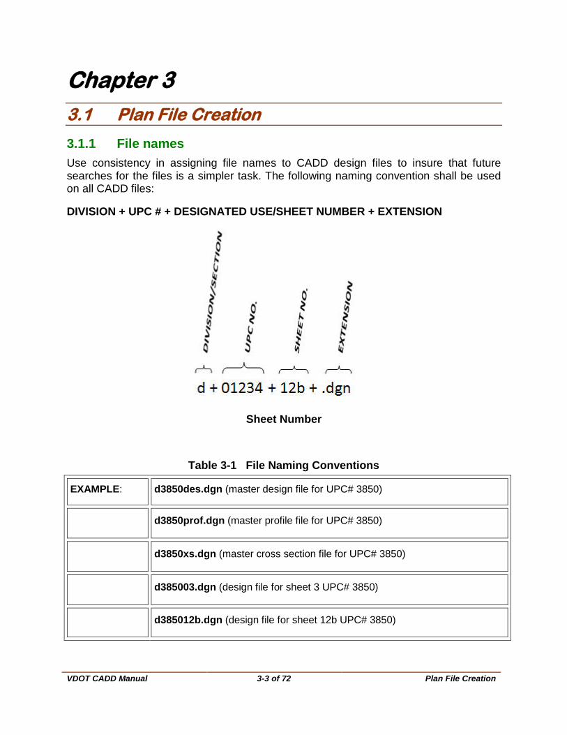
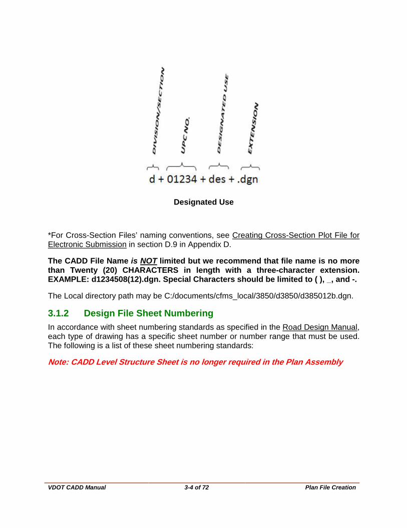
3.1.1 File names Use consistency in assigning file names to CADD design files to insure that future searches for the files is a simpler task. The following naming convention shall be used on all CADD files:
DIVISION + UPC # + DESIGNATED USE/SHEET NUMBER + EXTENSION
Sheet Number
Table 3-1 File Naming Conventions
EXAMPLE: d3850des.dgn (master design file for UPC# 3850)
d3850prof.dgn (master profile file for UPC# 3850)
d3850xs.dgn (master cross section file for UPC# 3850)
d385003.dgn (design file for sheet 3 UPC# 3850)
d385012b.dgn (design file for sheet 12b UPC# 3850)
VDOT CADD Manual
3-4 of 72 Plan File Creation
Designated Use
*For Cross-Section Files’ naming conventions, see Creating Cross-Section Plot File for Electronic Submission in section D.9 in Appendix D.
The CADD File Name is NOT limited but we recommend that file name is no more than Twenty (20) CHARACTERS in length with a three-character extension. EXAMPLE: d1234508(12).dgn. Special Characters should be limited to ( ), _, and -.
The Local directory path may be C:/documents/cfms_local/3850/d3850/d385012b.dgn.
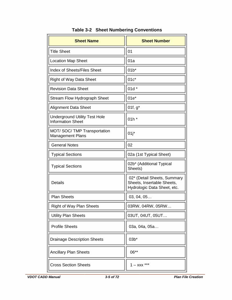
3.1.2 Design File Sheet Numbering In accordance with sheet numbering standards as specified in the Road Design Manual, each type of drawing has a specific sheet number or number range that must be used. The following is a list of these sheet numbering standards:
Note: CADD Level Structure Sheet is no longer required in the Plan Assembly
VDOT CADD Manual
3-5 of 72 Plan File Creation
Table 3-2 Sheet Numbering Conventions
Sheet Name Sheet Number
Title Sheet 01
Location Map Sheet 01a
Index of Sheets/Files Sheet 01b*
Right of Way Data Sheet 01c*
Revision Data Sheet 01d *
Stream Flow Hydrograph Sheet 01e*
Alignment Data Sheet 01f, g*
Underground Utility Test Hole Information Sheet 01h *
MOT/ SOC/ TMP Transportation Management Plans 01j*
General Notes 02
Typical Sections 02a (1st Typical Sheet)
Typical Sections 02b* (Additional Typical Sheets)
Details 02* (Detail Sheets, Summary Sheets, Insertable Sheets, Hydrologic Data Sheet, etc.
Plan Sheets 03, 04, 05…
Right of Way Plan Sheets 03RW, 04RW, 05RW…
Utility Plan Sheets 03UT, 04UT, 05UT…
Profile Sheets 03a, 04a, 05a…
Drainage Description Sheets 03b*
Ancillary Plan Sheets 06**
Cross Section Sheets 1 – xxx ***

VDOT CADD Manual
3-6 of 72 Plan File Creation
*The Lead Design Engineer assigns the Alpha Letter to sheets. Numbering in the “1” series may need to be adjusted to allow for the exclusion of sheet(s), such as the Project Location Map.
**Ancillary plans(Utility Relocation, Lighting, Signs, Traffic Control Devices, Landscaping, Bridge, etc.), which are to be incorporated into the Plan Assembly, are to be assigned PLAN SERIES NUMBERS BEGINNING AFTER THE LAST PLAN SHEET NUMBER BY THE LEAD DESIGN ENGINEER, in coordination with the PROJECT MANAGER. BRIDGE PLANS have their own sheet numbering system. Place their plans after the Cross Sections in the plan assembly.
*** Main Cross Section Sheets are numbered and placed in accordance with GEOPAK sheet numbering.
3.1.3 Seed Files Create all design files from a seed file. A separate and specific seed file has been developed for each type of design file. For example, there is a different seed file for metric or imperial plan sheets, general notes sheets, typical section sheets, etc. For additional information, see MicroStation/OpenRoads Standards 2016 seed files.
NOTE: New 2014 Format: Code of Virginia Section 55-290 - Plane coordinates used in systems states “The plane coordinates of a point on the earth's surface, to be used in expressing the position or location of such point in the appropriate zone of these systems, shall be expressed in U.S. survey feet and decimals of a foot. When converting coordinates in the Virginia Coordinate System of 1983 from meters and decimals of a meter to feet and decimals of a foot, the U.S. survey foot factor (one foot equals 1200/3937 meters) shall be used. “
Currently VDOT uses imperial units in all MicroStation files. VDOT will continue to use the legacy seed files for existing projects life cycle (in imperial units) only.
In an effort to comply with the code listed above, VDOT is providing new seed files for NEW projects with units set to US Survey Feet for new project assignments after June 1, 2015. Files will note the seed file used to begin the project. All VDOT and consultant staff are responsible for verifying and using the proper seed file when work is assigned.
Any Microstation file that shows or reference the survey file will need to utilize the new seed files to comply with the change to US Survey Feet.

VDOT CADD Manual
3-7 of 72 Plan File Creation
3.1.3.1 New MicroStation Seed Files
Table 3-3 New Seed Files
Discipline Name Description
Design Files geopakdesv14.dgn Standard seed file for creating the design
Design Files geopakdtmv14.dgn Standard seed file for creating 3d files for Design
Design Files geopakprofv14.dgn Standard seed file for creating profiles
Design Files geopakworkv14.dgn Standard seed file for creating the work file
Design Files Geopakworkv14.dgn GEOPAK seed file for pattern lines, shapes, template separator., etc.
Survey USFootSeed.dgn Standard seed file for creating 2d files
Survey USFootSeed3D.dgn Standard seed file for creating 3d files
Right of Way RWDATA.dgn Standard Right of Way data table
All other seed files remain the same. They do not deal with the survey file.
3.1.3.2 Unchanged MicroStation Seed Files
Table 3-4 Seed Files
Name Description
geopakxsht.dgn GEOPAK seed file for cross section sheet file
guidesign.dgn GuideSign seed file for sign design
mgeopakdes.dgn Metric GEOPAK seed file for Master Design file

VDOT CADD Manual
3-8 of 72 Plan File Creation
Name Description
mgeopakdtm.dgn Metric GEOPAK seed file for triangles and contour file
mgeopakprof.dgn Metric GEOPAK seed file for Master Profile files
mgeopakwork.dgn Metric GEOPAK seed file for pattern lines, shapes, template sep., etc.
mgeopakxs.dgn Metric GEOPAK seed file for Master Cross Section Files
mgeopakxsht.dgn Metric GEOPAK seed file for cross section sheet file
mpcseed.dgn Metric seed file for Plan Coordination Section
mseed.dgn generic Metric seed file
mseedpla.dgn Metric seed file for Plan Sheet creation
mseedtil.dgn Metric seed file for Title Sheet creation
mseedtyp.dgn Metric seed file for Typical Section Sheet
mseed3d.dgn generic Metric 3d seed file
matseedv8i.dgn standard seed file for Gint
public hearing seed.dgn Imperial seed file for Public Hearing Display
eng-ser seed.dgn Imperial seed file for Insertable Sheet
Vdotseed.dgn generic Imperial seed file
VDOT CADD Manual
3-9 of 72 Plan File Creation
3.1.3.3 Operating Parameters The above seed files have several operating parameters set specific to that sheets purpose and scale. Some of the parameters are as follows:
• Working units: Imperial -- FT, TH, 1000, 1 Metric -- M, M, 1, 1000
• Global origin set to lower left (GO=0,0)
• Coordinate readout: Master Units to 4 decimal accuracy
• Angles: DD.DDDD, Conventional to 2 decimal display for Imperial projects, and 3 decimal display for metric projects
• All levels are turned on (ON=1-63)
• Data read-out is set to master units with a minimum of two decimal places displayed
• View control delays are turned off
• All fast displays are turned off
• Text node display is turned off
VDOT CADD Manual
3-10 of 72 Title Sheet
3.2 Title Sheet
The following instructions are for creating a Title Sheet and apply to both Imperial and Metric units. (BOLD type denotes user key-ins and italics denote menu item selections.) For additional information, see IIM-LD-204.
3.2.1 Create a new file in Falcon Please see Falcon Instructions, for additional information on the proper method of creating a new design files.
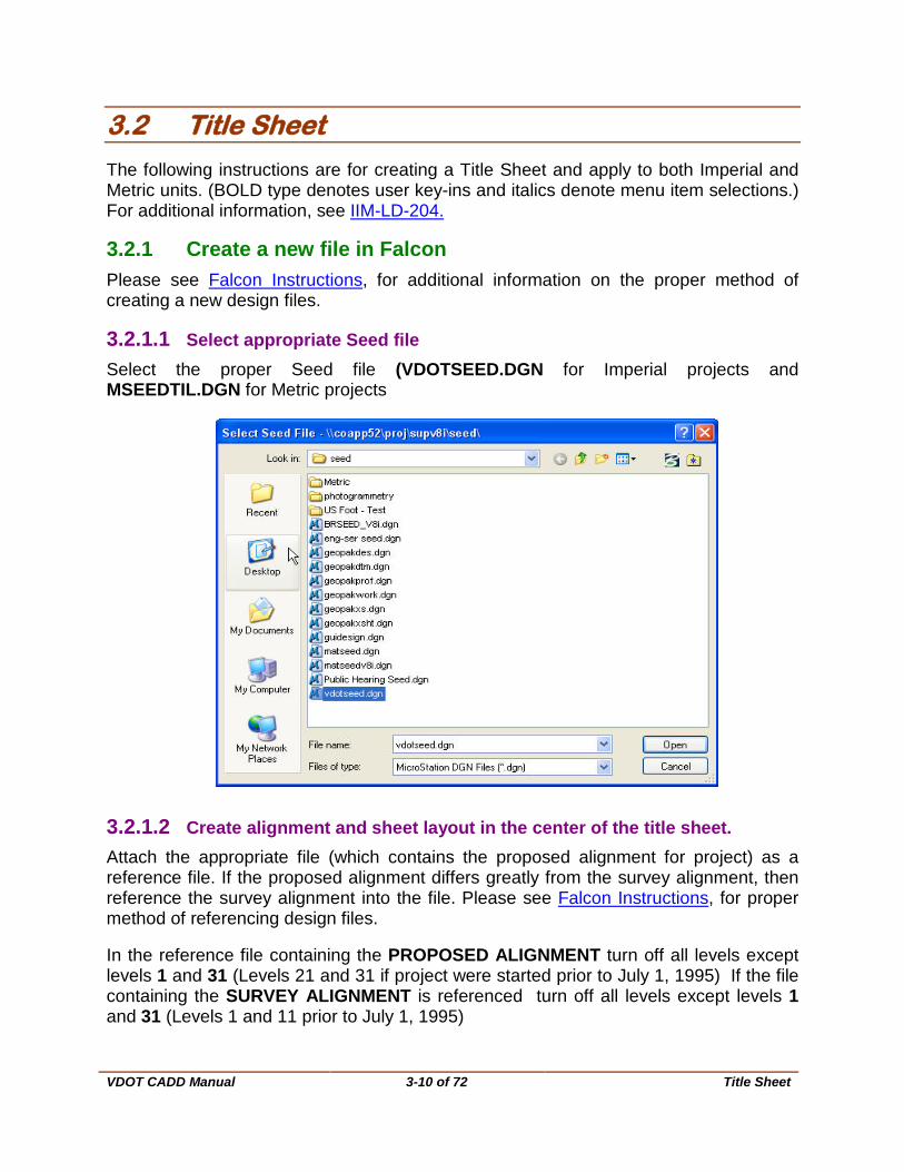
3.2.1.1 Select appropriate Seed file Select the proper Seed file (VDOTSEED.DGN for Imperial projects and MSEEDTIL.DGN for Metric projects
3.2.1.2 Create alignment and sheet layout in the center of the title sheet. Attach the appropriate file (which contains the proposed alignment for project) as a reference file. If the proposed alignment differs greatly from the survey alignment, then reference the survey alignment into the file. Please see Falcon Instructions, for proper method of referencing design files.
In the reference file containing the PROPOSED ALIGNMENT turn off all levels except levels 1 and 31 (Levels 21 and 31 if project were started prior to July 1, 1995) If the file containing the SURVEY ALIGNMENT is referenced turn off all levels except levels 1 and 31 (Levels 1 and 11 prior to July 1, 1995)

VDOT CADD Manual
3-11 of 72 Title Sheet
To turn off levels in reference file, choose File and Reference from the MicroStation Menu Bar. When the Reference Files dialog box opens, select the correct reference file, choose the Level Display option from the Settings menu, and turn off appropriate levels. It may be necessary to move the sheet border so that it encompasses the alignment file.
It may be necessary to reduce the scale of the reference file so that the entire alignment will fit neatly into the title sheet. If the project is short enough, you may want to consider increasing the scale of the references. To change the scale select File from the MicroStation Menu Bar and then select the Reference option. When the Reference File dialog box open, choose the Scale option from the Tools menu item and change the scale as necessary. Take care that you have the appropriate reference file highlighted prior to changing the scale. If you scale down the reference file, you will also need to scale up the text sizes proportionally so they are readable. Turn on reference level 31 that contains the 500' (100 M) station references. Copy station text into the title sheet file and place on level 61 (level 60 prior to July 1, 1995); then turn off reference level 31. To copy station text, use the Element Selection Tool to identify the text and then use the Copy command. When prompted for the second data point, key-in DL=0. Now turn off the reference level 31. Now all that should be visible is the alignment and the station calls. Scale up the station numbers so that they are readable.
The next step is to reference in the individual sheet files that have the sheet borders. Trace each border with a Line String on level 61 (level 60 prior to July 1, 1995), LC=3 and WT=3. When you are finished tracing each border, detach the individual sheet references. Now you should have the entire project alignment with 500' (100 M) station numbers and limits of each plan sheet shown in the center of the title sheet.
3.2.1.3 Complete Title Sheet Complete Title Sheet by editing text for Project Number etc. If you use the Find/Replace Text command make sure the toggle for In Cells is turned on.
The Find/Replace Text command is under the Edit pulldown on MicroStation's Menu Bar.
3.2.1.4 All text sizes All text sizes should be the same as text sizes on title sheet cell except description headings.
Set text sizes in headings as follows: TX=48 LS=24 WT=10 Imperial TX=12 LS=6 WT=10 Metric
The text size for project number below description is as follows: TX=24 LS=12 WT=5 Imperial TX=9 LS=4.5 WT=5 Metric

VDOT CADD Manual
3-12 of 72 Title Sheet
3.2.1.5 Sample Title Sheets Figure 3-5 Imperial Title sheet
Figure 3-6 Metric Title sheet
VDOT CADD Manual
3-13 of 72 Title Sheet
Sample title sheets (Imperial and Metric) shown with the appropriate text sizes, etc. This figure is for your reference and information only. For additional information, see the Road Design Manual.
NOTE: There are times when some proposed work can be shown on title sheets but only when the project is very short and the title sheet scale is large.
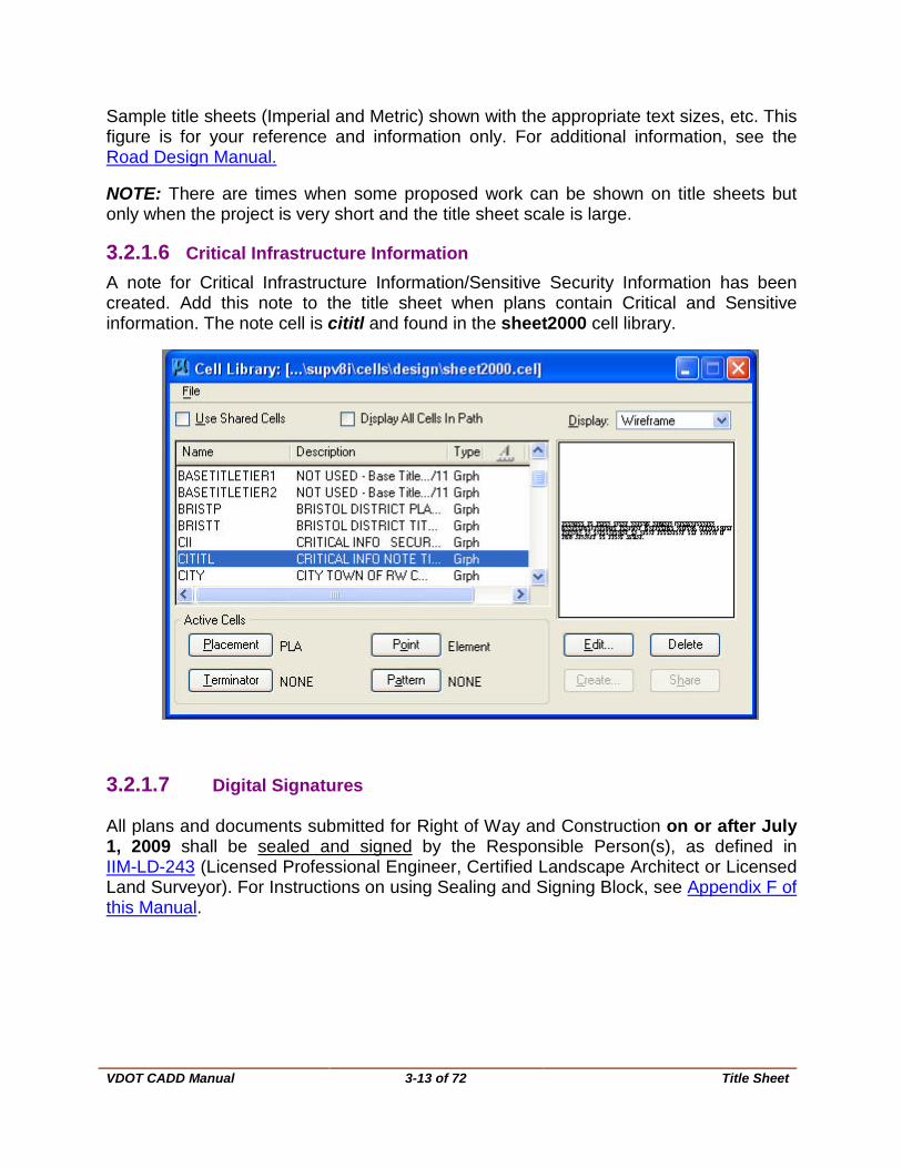
3.2.1.6 Critical Infrastructure Information A note for Critical Infrastructure Information/Sensitive Security Information has been created. Add this note to the title sheet when plans contain Critical and Sensitive information. The note cell is cititl and found in the sheet2000 cell library.
3.2.1.7 Digital Signatures All plans and documents submitted for Right of Way and Construction on or after July 1, 2009 shall be sealed and signed by the Responsible Person(s), as defined in IIM-LD-243 (Licensed Professional Engineer, Certified Landscape Architect or Licensed Land Surveyor). For Instructions on using Sealing and Signing Block, see Appendix F of this Manual.

VDOT CADD Manual
3-14 of 72 Location Map
3.3 Location Map
The following guidelines are to be used for creating a Location Map that applies to either Imperial or Metric projects. All of the County Maps are located in InsideVDOT. These maps are not modified for MicroStation use. Use only as reference files. Please do not try to copy the data into your Location Map file. The working units in the map files are not compatible with the working units in our standard graphics files.
3.3.1 Create a Location Map Sheet.
Please see Falcon Instructions, for proper method of creating new design file.
Select the proper Seed file (GEOPAKDES.DGN for Imperial projects). Working Units for all maps are in Feet and Inches.
Place the sheet using the PLA2 cell from the sheet2000 cell library at a scale of 1. After sheet is created you can locate the county map you need.

VDOT CADD Manual
3-15 of 72 Location Map
3.3.2 Find Location Maps
The most up to date County Maps are no longer located in Falcon, to access maps use this link: https://insidevdot.cov.virginia.gov/div/pa/MAPS/SitePages/Home.aspx *Consultants should contact the Project Manager for a copy of project maps if needed and then follow instructions for creating a Location Map Sheet.
Or Go to InsideVDOT → Business → Communications:
Click on Maps on the sidebar: under Communications Program Areas:

VDOT CADD Manual
3-16 of 72 Location Map
The maps are stored in both PDF and JPG format. Choose the PDF folder; it produces a crisper print in MicroStation.
A list of all the County Road Maps will appear:

VDOT CADD Manual
3-17 of 72 Location Map
Find correct County for your project, right click on name and select Save Target As :
Save File (map) to your C:\documents\cfms_local\UPC#\dUPC# folder. (This will need to be added to Falcon)

VDOT CADD Manual
3-18 of 72 Location Map
3.3.2.1 Reference appropriate county map to design file The county map dgn file is stored in C:\documents\cfms_local\UPC#\dUPC# folder. The UPC # is county maps and the division is the county you select to work with. In MicroStation, go to File→ Raster Manager
Navigate to your map you saved in C:\documents\cfms_local\UPC#\dUPC# folder, Select the map and click Open. Be sure to set the Attachment Options to Place Interactively. Click on Attach.
3.3.3 County Map DGN Files
Select a point inside the lower left of your plan sheet and then at the upper right. A dashed outline of the map will follow your cursor. Once you select the top right your map will appear. If you wish to use the whole county map as shown, you are done. If you need to manipulate it, continue on.
VDOT CADD Manual
3-19 of 72 Location Map
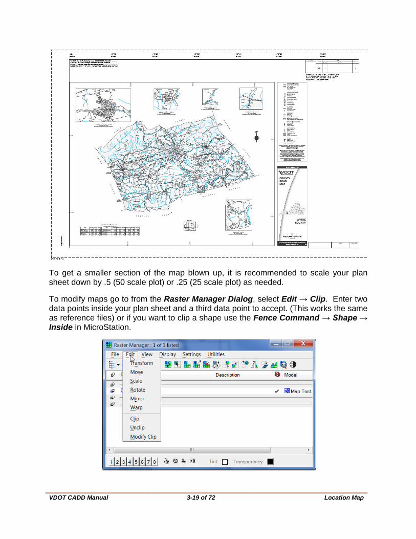
To get a smaller section of the map blown up, it is recommended to scale your plan sheet down by .5 (50 scale plot) or .25 (25 scale plot) as needed.
To modify maps go to from the Raster Manager Dialog, select Edit → Clip. Enter two data points inside your plan sheet and a third data point to accept. (This works the same as reference files) or if you want to clip a shape use the Fence Command → Shape → Inside in MicroStation.
VDOT CADD Manual
3-20 of 72 Location Map
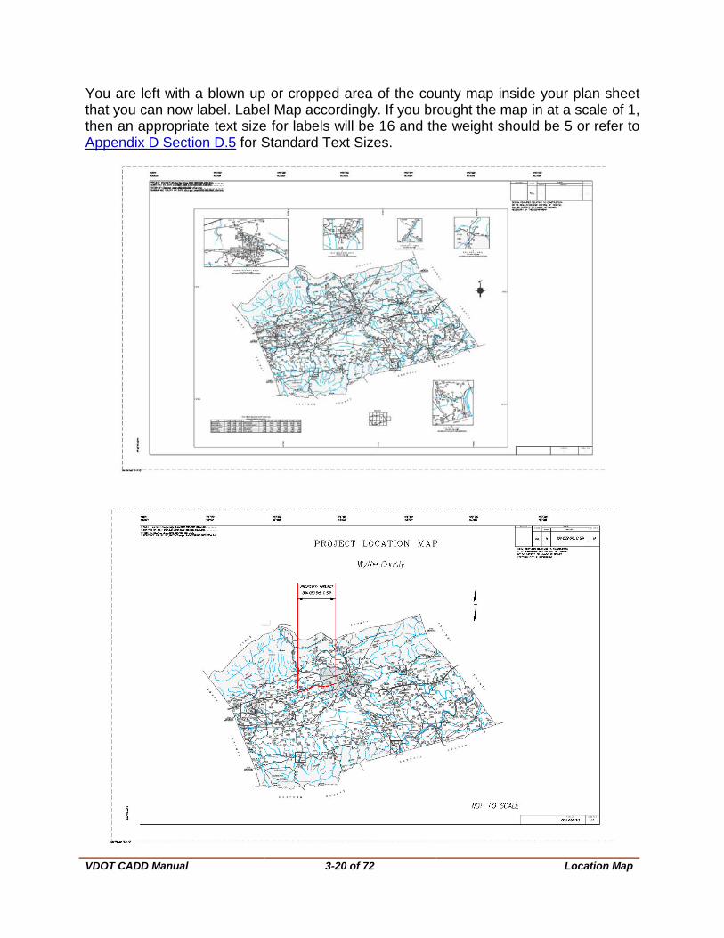
You are left with a blown up or cropped area of the county map inside your plan sheet that you can now label. Label Map accordingly. If you brought the map in at a scale of 1, then an appropriate text size for labels will be 16 and the weight should be 5 or refer to Appendix D Section D.5 for Standard Text Sizes.

VDOT CADD Manual
3-21 of 73 Index of Sheets
3.4 Index of Sheets
All projects shall have an Index of Sheets in the plan assembly; it will follow the Location Sheet (on “C” projects) and is to be numbered “1B”. Subsequent sheets needed for the Index of Sheets are to be numbered 1B(1), 1B(2), etc. The Index of Sheets should progress as files are created during plan development. This sheet is available in the Sheet Cell Library, sheet2000.cel. For additional information, see the Road Design Manual.
VDOT CADD Manual
3-22 of 72 General Notes
3.5 General Notes
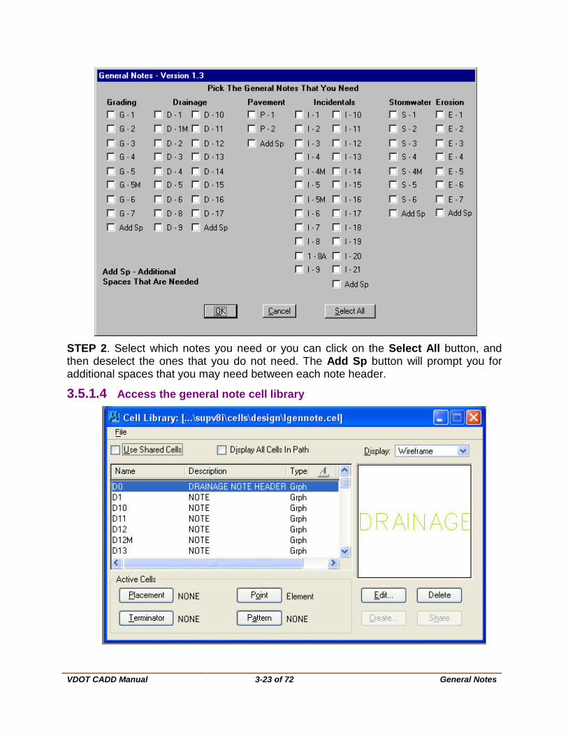
The creation of the General Notes sheet has been automated with a macro named gnote.ba. This macro (program) uses the cell library lgennote.cel, which contains the cells of all standard notes. These notes are called in and placed on the design file with the program calculating the spacing automatically. All standard general notes can be generated using this program. All non-standard notes will have to be added by the CADD operator using the MicroStation text commands.
The following instructions are for creating a General Notes Sheet and applies to both English and Metric projects. (BOLD type denotes user key-ins and italics denote menu item selections.)
3.5.1 Create a new General Notes Sheet
3.5.1.1 Create a new file in Falcon Please see Falcon Instructions, for the proper method of creating new design file.
Select the proper Seed file (VDOTSEED.DGN for Imperial or Metric projects)
3.5.1.2 Access the general note macro In the MicroStation key-in window, type “macro gnote”, and then hit enter or click on the run key-in icon button. Please see instructions for using Gnote Macro below.
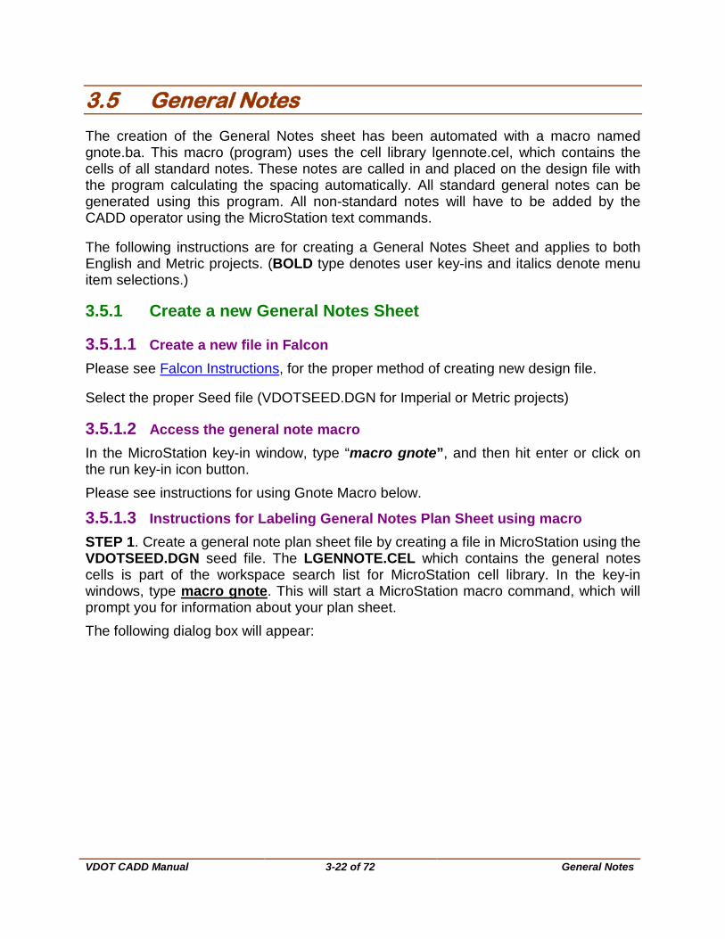
3.5.1.3 Instructions for Labeling General Notes Plan Sheet using macro STEP 1. Create a general note plan sheet file by creating a file in MicroStation using the VDOTSEED.DGN seed file. The LGENNOTE.CEL which contains the general notes cells is part of the workspace search list for MicroStation cell library. In the key-in windows, type macro gnote. This will start a MicroStation macro command, which will prompt you for information about your plan sheet. The following dialog box will appear:
VDOT CADD Manual
3-23 of 72 General Notes
STEP 2. Select which notes you need or you can click on the Select All button, and then deselect the ones that you do not need. The Add Sp button will prompt you for additional spaces that you may need between each note header.
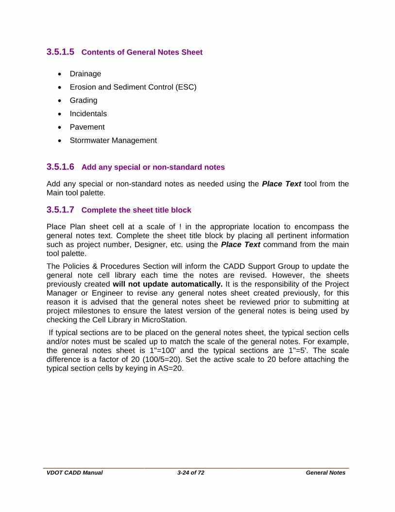
3.5.1.4 Access the general note cell library
VDOT CADD Manual
3-24 of 72 General Notes
3.5.1.5 Contents of General Notes Sheet
• Drainage
• Erosion and Sediment Control (ESC)
• Grading
• Incidentals
• Pavement
• Stormwater Management
3.5.1.6 Add any special or non-standard notes
Add any special or non-standard notes as needed using the Place Text tool from the Main tool palette.
3.5.1.7 Complete the sheet title block
Place Plan sheet cell at a scale of ! in the appropriate location to encompass the general notes text. Complete the sheet title block by placing all pertinent information such as project number, Designer, etc. using the Place Text command from the main tool palette. The Policies & Procedures Section will inform the CADD Support Group to update the general note cell library each time the notes are revised. However, the sheets previously created will not update automatically. It is the responsibility of the Project Manager or Engineer to revise any general notes sheet created previously, for this reason it is advised that the general notes sheet be reviewed prior to submitting at project milestones to ensure the latest version of the general notes is being used by checking the Cell Library in MicroStation. If typical sections are to be placed on the general notes sheet, the typical section cells and/or notes must be scaled up to match the scale of the general notes. For example, the general notes sheet is 1"=100' and the typical sections are 1"=5'. The scale difference is a factor of 20 (100/5=20). Set the active scale to 20 before attaching the typical section cells by keying in AS=20.

VDOT CADD Manual
3-25 of 72 General Notes
Figure 3-7 General Notes sheet

VDOT CADD Manual
3-26 of 72 Cross Section Labeling
3.6 Cross Section Labeling
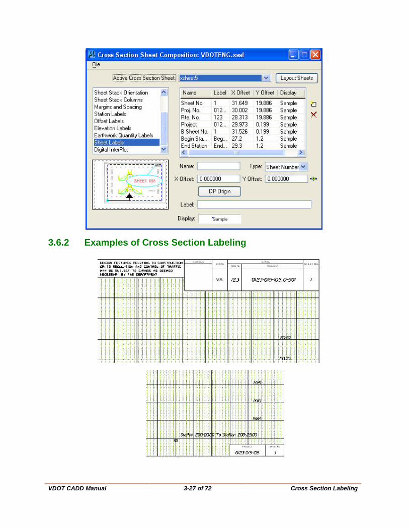
3.6.1 Instructions for Labeling Cross Section Plan Sheets Cross section labeling is done with the Geopak Cross Sheet Layout Tool.
• Open the Cross Section Sheet Composition dialog box as shown below. • Scroll down to Sheet Labels. In this area of the application, users can type in the
Project Number and Route Number that is to be placed on each cross section sheet.
• Double click under the Label column where it reads "0123-015-105, C501" and type in the Project Number to be place at the top right corner of the cross section sheet.
• Double click under the Label column where it reads "123" and type in the Route Number to be place at the top right corner of the cross section sheet.
• Double click under the Label column where it reads "0123-015-105" and type in the Project Number to be place at the bottom right corner of the cross section sheet. These columns widths can be adjusted by clicking the vertical line separator and sliding sideways.
• By default the Sheet No. numbering starts with "1". This field can be modified also.
• Once all the pertinent information is type in the user can click on the Layout Sheets button and process the sheets.
VDOT CADD Manual
3-27 of 72 Cross Section Labeling
3.6.2 Examples of Cross Section Labeling

VDOT CADD Manual
3-28 of 72 Macros
3.7 Macros
3.7.1 VDOT Macros
The VDOT standard Macros are located in \\coapp52\proj\supV8i\road\macros. These macros are most beneficial in simplifying various functions of the CADD operators. There is room for expansion of the contents of the directory with other existing programs not currently included. New programs may be created or existing ones modified as needs dictate; however, no modifications to programs or additions to the directory shall be made without the permission of the Location and Design CADD Manager.
gnote.ba -This Macro automates the placement of general notes on a plan sheet. See section 3.5.1.3 for instructions on use of gnote.
Additional Macros can be accessed thru the Task Dialogue Box in MicroStation. Click on the Road tab. In the “S” row as shown below. Users may launch the macro by clicking on the green square icons. These macros are:
• Grade and Super Elevation Report
• Slope and Staking Report
• Super Elevation Diagram
• Right of Way Report
• Horizontal and Vertical Curve Labeling
• Grading Table

VDOT CADD Manual
3-29 of 72 Roadway Typical Sections
3.8 Roadway Typical Sections
Typical sections have been standardized for statewide use on all right of way and construction projects. The standards consist of seven different typical sections, which will fit most any roadway designed by VDOT. These sections are stored as cells located in the master state cell libraries \\coapp52\proj\supv8i\cells\design\stdtyp95.cel for English projects and \\coapp52\proj\supv8i\cells\mdesign\mstdtyp95.cel for Metric projects.
DO NOT MODIFY THESE CELLS UNLESS APPROVED BY THE CADD MANAGER.
The format as established in the typical sections should always be adhered to. However, the typical sections can be modified to meet project needs once they have been placed in the design file.
3.8.1 Changes Allowed in Typical Sections • Widths of pavement
• Slopes, if different from standards
• Adding median, traffic barriers, etc
• Adding topsoil, seeding, etc.
• Adding appropriate typical section names and stations
3.8.2 Typical Section Sheet in Falcon 3.8.2.1 Create a new file Please see Falcon Instructions, for the proper method of creating new design file. Select the proper Seed file (VDOTSEED.DGN for Imperial projects and MSEEDTYP.DGN for Metric projects) The user will have to place the appropriate plan sheet cell in the design file for imperial projects but the design file for metric projects will have a blank plan sheet in it.
3.8.2.2 Fill in all pertinent information Fill in all pertinent information such as project number, sheet number, route, Project Manager, Surveyor, Design Supervisor, Designer, etc.
3.8.2.3 Place appropriate cell(s) Place appropriate cell(s) from the Cell Library to create typical sections as required, including blowups and pavement patterns.
NOTE: Examples of all typical section cells and text needed to create the typical section sheets are shown below and in Appendix C of this manual.

VDOT CADD Manual
3-30 of 72 Roadway Typical Sections
3.8.2.4 Examples of Typical Section Sheet Figure 3-8 Imperial Typical Section Sheet
VDOT CADD Manual
3-31 of 72 Roadway Design for Total CADD
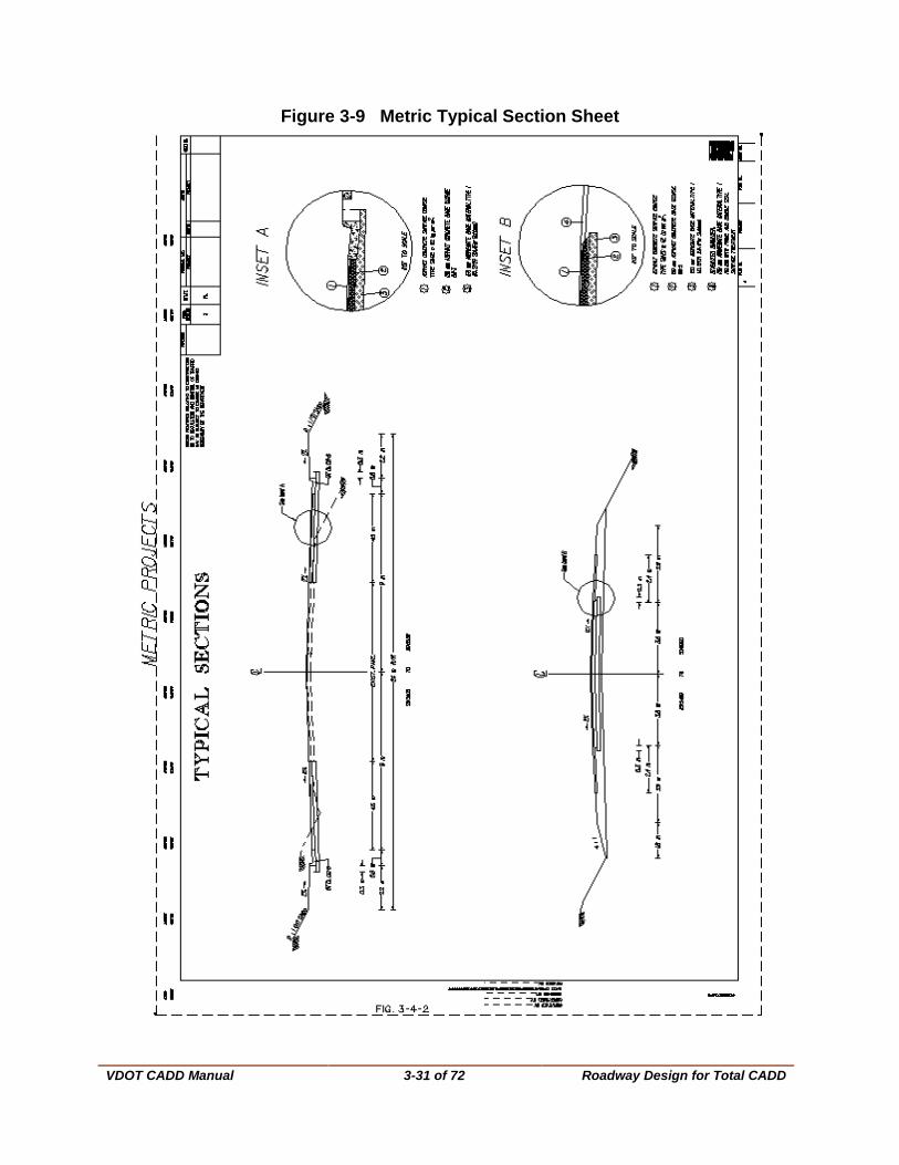
Figure 3-9 Metric Typical Section Sheet
VDOT CADD Manual
3-32 of 72 Roadway Design for Total CADD
3.9 Roadway Design for Total CADD 3.9.1 Development of Plans After notification of completed survey from State Survey Parties Engineer, the Project Manager will request that preliminary design development begin. The letter notifying the engineer of the completed survey will include both project file name and design scale. The steps involved in the preliminary design development are outlined below. If no additional location studies are necessary, plans for a Preliminary Field Inspection can begin. The required plan work involved for the Preliminary Field Inspection (PFI), Public Hearing (PH), Field Inspection (FI), Right of Way (RW) and Final Submission (FS) milestones of the project are outlined in the Electronic Plan Submission Process Flow Chart and will be checked in accordance with the Quality Control Checklist. Plan Rolls and Profile Rolls, in lieu of plan and profile sheets, are acceptable for the PFI and PH Stages, unless the Project Manager would prefer plan and profile sheets be prepared for those stages.
3.9.1.1 Create the master design file Create the master design file with naming convention in accordance with Chapter 3 Section 1. No sheet number is required since this will be the master file.
DIVISION + UPC # + DESIGNATED USE + EXTENSION Example: d3850des.dgn
3.9.1.2 Attach Cell Libraries The dsymgeo.cel and mdsymgeo.cel cell libraries are now legacy cells. After 2014 and with the addition of MicroStation/OpenRoads we use dsymgeo2015.cel. for Design creation. For more information, see “Cells” in MicroStation/OpenRoads Standards 2016 If you are using GEOPAK then the Design Computation Manager Tool Box is preferred. If GEOPAK is not used, then attach dsymgeo.cel library for imperial projects or mdsymgeo.cel library for metric projects.
Workspace Configurations in MicroStation have been setup by VDOT’s CADD Support Section to defined paths to folders where cell libraries are located. When the user opens the cell library dialog box and clicks on “File” a list of the cell libraries is displayed. The user can pick the appropriate cell library.
The above cells are found in Appendix D, Section 8 of this manual.
NOTE: Set active scale based on the project scale. Example: AS=0.25 for 25 scale Imperial plan or 250 scale Metric plan.
VDOT CADD Manual
3-33 of 72 Roadway Design for Total CADD
3.9.1.3 Keep Master Design files intact Keep the master design files intact as your "roadway design files" for inputting all roadway design items throughout the life of the project. Do not place design items or annotation for design items in the individual sheet files. However, place notes, special symbols, reference notations, and symbol legends can be placed in sheet files.
This master design file will have the survey file referenced to it. This master survey file will initially be unlocked so that the designers can move text that overlaps their design. When updating the master survey file, lock the original survey file, thus preventing the designer from moving the text.
NOTE: DO NOT COPY the locked Survey File to a new file and make changes to the new file. It creates a situation where the Designer’s changes will be lost when the Survey Master File is updated and unlocked. Reference all other necessary files at this time also.
When submittal of the plans is necessary, the master file can be clip-bound into the sheet files for plotting. Create the actual plan sheets using the clip bound method at the appropriate stage of development and will be addressed later in this chapter. Multiple users can use the master design file, though close coordination between the various files is critical. When several users need to develop their design in the master file, the only way to accommodate this is to reference the master file to several other design files. Copy each uniquely named design file later into the master file before submittals. For example, an engineer may want to divide a three-mile project into three separate one-mile segments. Each segment will reference the master design file. CADD operators can work concurrently on their segment of the project at submittal stages. The master design file can be loaded into MicroStation and each segment referenced and copied into it. When you copy the segments back into the master file, delete the segment files. It is critical that each segment file have a unique file name. Add a qualifier to the end of the filename, i.e., a or a 1 (d3850desa.dgn or d3850des1.dgn).
3.9.2 Alignments Enter all alignments for new projects using the Departments current automated engineering design package GEOPAK. See GEOPAK Training Manuals Cogo Geometry Section 3-2 for details.
VDOT CADD Manual
3-34 of 72 Roadway Design for Total CADD
3.9.3 CADD Development 3.9.3.1 Use of Levels, Weights, Line Codes, and Colors Place all lines, cells or other graphic elements necessary to illustrate the design in the design file in accordance with the current level structure as detailed in Appendix D Section 4 of this manual. Place all proposed items in the file using the proper levels, line weights, line codes, and colors as established by the Standards Committee. The use of the Quantity Input tool D&C Manager (GEOPAK) will assure that all items are in accordance with those standards. Details of these standards are in Appendix D of this manual. The D&C Manager is located under Applications, GEOPAK Road Tools in the pulldown menu in MicroStation or in Main Tool Box of Task Manager.
NOTE: Electronic files are available to contractors for projects designed on CADD and located in Falcon. The need for placing items on proper levels is of utmost importance, See Appendix D, Section 4.2.
3.9.3.2 Annotation Instructions 3.9.3.2.1 Proposed Work Annotate all proposed work on projects in lieu of designations that require legends for explanations. When possible, label each continuous proposed work item once at each side of the roadway per plan sheet. This will decrease the amount of plan clutter. See Using the Place Note Command document for annotating with leader lines and terminators or use the Plan View Labeling tool in GEOPAK See Appendix D Section 5 of this manual for text sizes and weights.
3.9.3.2.2 Use of Legends Complex projects that involve dense topography and proposed work will require the use of special legends. These legends must incorporate the standard symbols as specified in the Road Design Manual. Designer must review all legends for consistency with the plans.
3.9.3.2.3 Standard Symbols Some construction items incorporate standard symbols in lieu of labeling. These symbols are included in a legend at the bottom of the plan sheet. Erosion control items, construction limits, and crosshatching for demolition of pavement are examples of such symbols. 3.9.3.2.4 Use of "Proposed" and "Required" The term "Proposed" applies to roadways, lanes, interchanges and other items that are not construction items in the contract. The term "Required" applies to all paid items that the contractor is constructing.
VDOT CADD Manual
3-35 of 72 Roadway Design for Total CADD
3.9.3.2.5 Labeling Alignments
Label all field survey lines "Survey Baseline." Label the alignment used to build the road "Construction Baseline." If you create an office-revised line for obtaining survey, but do not use it for construction, label it "Office Revised Baseline."
3.9.3.2.6 Dimensioning When dimensioning such items as existing right of way, proposed pavement, medians, etc., which are consistent throughout a plan sheet only need to be dimensioned once on each sheet. However, in areas where there are median breaks, intersections and other configurations, additional dimensioning may be required.
3.9.3.2.7 Arrows on Power Poles The arrows indicating that power poles are within the construction limits are no longer required on the plans if the poles are not to be relocated.
3.9.3.2.8 Utility Data On projects that have an Underground Utilities Test Hole Information Sheet, the utility owners name, address and phone number are to be shown on the sheet, and only the utility owners name should appear on the plan sheet. Projects with minimal utility involvement and without a utility data sheet will continue to list all information on each plan sheet. Access the Test Hole Information Sheet as a cell in the Sheet 2000.cel library.
3.9.3.2.9 Unapproved Stamps
Place the following note in each sheet design file prior to approval for Right of Way. This note can be found in the dsymgeo.cel and mdsymgeo.cel, library (AC=UNRWC).
"THESE PLANS ARE UNFINISHED AND UNAPPROVED AND ARE NOT TO BE USED FOR ANY TYPE OF CONSTRUCTION OR THE ACQUISITION OF RIGHT OF WAY."
3.9.3.3 Plots for PFI Meeting The Lead Design Engineer is to check with the Project Manager for the roll or plan assembly and scale size required for the PFI Meeting. See Appendix G for complete instructions Preliminary Field Inspection.
3.9.3.4 Use of CADConform Software Use CADConform to check the validity of items in the Master DGN files. It is recommended that all files be scanned at each milestones of project development. Maintain reports generated by the scanning and checking of files in the project directory through Falcon DocMan
.
VDOT CADD Manual
3-36 of 72 Roadway Design for Total CADD
3.9.3.5 Pattern Reference File Perform all necessary pavement stippling and demolition of pavement cross-hatching in a design UPC#.pat file. Reference the UPC#.pat file into the sheet design files in accordance with instructions in Appendix D Section 2 of this manual.
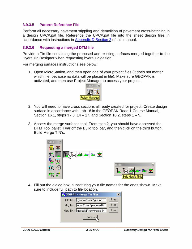
3.9.3.6 Requesting a merged DTM file Provide a Tin file containing the proposed and existing surfaces merged together to the Hydraulic Designer when requesting hydraulic design. For merging surfaces instructions see below:
1. Open MicroStation, and then open one of your project files (it does not matter which file, because no data will be placed in file). Make sure GEOPAK is activated, and then use Project Manager to access your project.
2. You will need to have cross sections all ready created for project. Create design surface in accordance with Lab 16 in the GEOPAK Road 1 Course Manual, Section 16.1, steps 3 - 5, 14 – 17, and Section 16.2, steps 1 – 5.
3. Access the merge surfaces tool. From step 2, you should have accessed the
DTM Tool pallet. Tear off the Build tool bar, and then click on the third button, Build Merge TIN’s.
4. Fill out the dialog box, substituting your file names for the ones shown. Make sure to include full path to file location.
VDOT CADD Manual
3-37 of 72 Roadway Design for Total CADD
3.9.4 Development of Plans for Preliminary Field Inspection
3.9.4.1 Incorporate all changes requested from the Preliminary Field Inspection Meeting into the master design file.
3.9.4.2 Create Base Plan Sheets This procedure can be done any time after the Preliminary Field Inspection Meeting review comment(s) have been incorporated into the design file, but is recommended to be done after Public Hearing. Consult the Project Manager prior to the Public Hearing to see if base plan sheets are necessary for that stage. Instructions for GEOPAK projects can be found in your Road 1 Training manual, chapter 18.
1. Create individual files for each sheet in accordance with Section 1 of this chapter.
2. Attach all appropriate survey files as a reference file. See Falcon Instructions, for proper method of attaching reference files.
3. Attach master design file as reference file (preliminary design file). See Falcon Instructions, for proper method of attaching reference files.
4. Place plan sheet in file at an active scale corresponding to the project scale and at the active angle to match the orientation of the project. Attach the proper scale bar for the scale of the project.
5. Key-in: AC=PLA AC=SBAR# (SBAR1, SBAR25 or SBAR50)
6. Confirm that locate and snap for each reference file is set on.
7. Once the above steps are completed, rotate the view and save the settings for batch plotting the file. Do not rotate the file itself. Correct coordinates must be maintained at all times and rotating a reference file will corrupt the coordinates. See Section 3.11.1 for details on MicroStation Print Organizer (Batch plotting). These instructions must be applied to all sheet files to be plotted.
8. Complete data on sheet files such as project numbers, sheet number, Engineer and designers names, etc. All of this data shall be placed on level 61.
9. Perform clip-bound procedure in accordance with instructions in Appendix D Section 2 of this manual.
VDOT CADD Manual
3-38 of 72 Roadway Design for Total CADD
3.9.4.3 Develop Design in Greater Detail Draft proposed entrances, crossovers and other incidental items that can be added at this time in the master design file.
3.9.4.4 Construction Limits The construction limits are handled by GEOPAK. See Road 1 Training manual, chapter 16 for symbology.
3.9.4.5 Intermediate Prints/PDFs A set of PDF files should be made and kept up to date (current drawings, etc.) to facilitate print on demand capabilities for other Divisions. See Generating and Submitting PDF Files/Archiving for instructions on creating PDF files.
3.9.4.6 Right of Way and Easements Proposed line work for Right of Way (including Limited Access Lines where applicable), permanent drainage easements, and temporary construction easements necessary for construction will be placed in the master Right of Way design file rUPC#+rw.dgn. Parcel Numbers and Demolition Numbers, as provided by District RW, will be shown in the master design file dUPC#+des.dgn). Utility Easements may not be available until after the Utility Field Inspection is held (after the FI), but these easements will be incorporated into the master Right of Way design file rUPC#+rw.dgn) before submittal of the RW Stage Plans.. See Chapter 5 on Right of Way / Easements and Utilities, for detailed information on the preparation of Right of Way plans.
3.9.4.7 Critical Infrastructure Information/Sensitive Security Information (CII/SSI) A note for Critical Infrastructure Information/Sensitive Security Information has been created. This note will have to be added to the plan sheets that contain Critical and Sensitive information. The note is called “cii “and is found in the sheet2000 cell library.
VDOT CADD Manual
3-39 of 72 Roadway Design for Total CADD
3.9.5 Traffic Maintenance Plans (TMP) TMP Plans should be prepared for Constructability Review Meetings as soon as possible in the early plan development stages, and are required in the FI Plans.
There are several methods of laying out a sequence of construction. Each project is different from every other project in some way. These are two suggestions of methods that can be used as a guide for your particular situation:
3.9.5.1 Method 1 Phase I
1. Create a new design file for the sequence of construction sheets. Attach the appropriate Reference Files. See Falcon Instructions, Pages 12 and 13 for proper method of attaching reference files.
2. Make the sheet cells large enough to encompass the area that you want to cover, by changing the active scale.
3. Clip-bound the reference file so that only the area inside the sheet is visible. Turn off desired levels in the reference file to eliminate unnecessary lines and text.
Phase II Use the reference file from Phase I to produce the sheets in Phase II. The proposed elements in Phase I will need to be shown as existing in Phase II. This can be accomplished by using element symbology on Phase I
3.9.5.2 Method 2 Phase I
1. Create a new design file for each sequence of construction sheet. 2. Attach the appropriate Reference Files. See Falcon Instructions, Pages 12
and 13 for proper method of attaching reference files. 3. Give each Reference File a UNIQUE logical name. 4. Turn off undesired levels to eliminate unnecessary lines and text.
Copy appropriate elements into new design file and make adjustments. Phase II
1. Use the design files from Phase I to produce the files in Phase II. 2. Copy appropriate elements into new design file, make adjustments and
show proposed items in Phase I as existing in Phase II. 3. If you need to insert additional elements, attach the same Reference File(s)
as in Phase I. 4. Repeat the above procedure for each Phase, as appropriate.

VDOT CADD Manual
3-40 of 72 Roadway Design for Total CADD
3.9.6 Develop Plans for Public Hearing 1. Incorporate all changes requested from the Preliminary Field Inspection Meeting
in the master design file. 2. Make necessary additions and/or modifications as described below for color
plots for Public Hearing if desired
3.9.6.1 General Guidelines for Public Hearing Plans Assembly
1. MicroStation limits vertices to 5000 for a shape 2. Line Weight for shapes should be 0 (zero) 3. Shapes should be placed with Fill Type set to Opaque 4. Fill option needs to be turned on in the View Attributes dialog box
Create all Public Hearing Displays in accordance with information provided in Appendix G of this manual.
3.9.7 Develop Plans for Right of Way 1. Make any changes to plans necessary as a result of the comments from the
Public Hearing, Field Inspection and Utility Field Inspection Meetings.
2. Remove "unapproved note" (UNRWC) and replace it with the following note in each sheet design file. This note can be found in the dsym.cel and mdsym.cel, library (AC=UNCONS).
"THESE PLANS ARE UNFINISHED AND ARE NOT TO BE USED FOR ANY TYPE OF CONSTRUCTION."
3. Update PDF files and Archive Project. See Generating and Submitting PDF Files/Archiving for instructions.
See Chapter 5 on Right of Way / Easements and Utilities, for detailed information on the preparation of Right of Way plans.

VDOT CADD Manual
3-41 of 72 Roadway Design for Total CADD
3.9.8 Develop Plans for Final Submittal 1. Complete any design details or changes in the master design file. Revise Plans
as necessary for any Right of Way Revisions required. Follow the Electronic Plan Submission Process Flow Chart and the Quality Control Checklist PAC column checklist requirements when completing plan assembly and plan summaries.
3.9.8.1 Digitized Signatures 1. In accordance with Mr. J. S. Hodge's memorandum dated April 19, 1991, it is
satisfactory to use digitized signatures on revised title sheets. The FHWA requires that plans be signed when they are submitted for PS&E. Possible future litigation requiring the testimony of the signatories necessitates the requirement of retaining the original signed title sheet. Therefore, the original signed title sheet MUST NOT be destroyed. To use digitized signatures, the sheet will have to be scanned. The scanned signatures can only be used on the project to which the original signatures apply. See Digital Signature Instructions.
2. Remove all "NOT INTENDED FOR CONSTRUCTION", notes prior to submitting for Plan Coordination Review. (After PAC comments have been made and prior to First Submission to Programming and Scheduling Division).
3. Submit electronic files (PDF’s) for Plan Coordination Review to Construction Division for Tier 2 Projects only.
4. For additional information on Tier1 and Tier 2 project criteria, see IIM-LD-249.
3.9.8.2 Review 1. See: Electronic Plan Submission Process Flow Chart for overview of all
submission procedures.
2. See Electronic Plan Coordination Review for revised instructions. Verification of the usage of proper levels MUST BE checked at this stage.
3. After all changes are made as a result of the Plan Coordination Review, see Electronic Advertisement Submission instructions.
3.9.9 Revisions after R/W or Final Submittal VDOT has instituted a new policy so that revisions are not overwriting original plan sheets but are saved as Revisions. When changes are made to Right of Way after R/W Acquisition Plan Stage it is now a requirement that all changes made are noted as REVISIONS and follow the procedures outlined below. Construction Revisions will continue to be done the same as in the past.

VDOT CADD Manual
3-42 of 72 Roadway Design for Total CADD
When making a Right of Way revision, make the changes in the appropriate Microstation file or files. Then change the Sheet # field in the Falcon database by adding a _r1, _r2, _r3 etc. to each sheet. For example: #3_r4 and #5_r4 means that sheets 3 and 5 are a part of (revision no. 4) as denoted on the Revision Data Sheet∗
Then change the Generate PDF database field to CURRENT DRAWINGS for all the sheets that are to be included in the revision. The MicroStation files are now ready for PDF files to be generated and submitted to Falcon.
Note: The pick list has been updated to remove Right of Way and Right of Way revision.
∗ Rev 3/17

VDOT CADD Manual
3-43 of 72 Roadway Design for Total CADD
When a formal Right of Way revision is ready to be processed, an email request is to be sent to the CADDSupport Helpdesk along with a copy of the LD-36 requesting the PDF files be updated in Current Drawings and a copy of the revised files for the formal revision be placed in the Right of Way Plan Room of Falcon.∗ The old files will be moved to a void folder under the project folder in the Right of Way plan file room. The UPC number will be removed by CADDSupport from the Falcon database field so that the void files no longer show up on Falcon Web. Revised files will be added to the Right of Way plan file room and will now show up on Falcon Web. For more information see the Road Design Manual Section 2F-5 and the Electronic Plan Submission Process Flow Chart.
Consultants will submit pdf files named in accordance with Chapter 1 Section1.4.3 in the CADD Manual.
For information on revised plans in the Plan File Room, see Chapter 1 Section 1.5.
∗ Rev 3/17

VDOT CADD Manual
3-44 of 72 Standards/Special Design
3.10 Standards/Special Design Section
The Standards/Special Design Section of Location and Design is responsible for all of the standard drawings shown in the Road Design Standards Imperial and Metric Manuals, and for the Insertable Sheet updates for those Standards. They also prepare Special Design Detail Sheets for project specific situations when modifications to Standard details are necessary.
3.10.1 CADD Drawing Standards (Imperial) MicroStation
Working units are located in the "settings menu". All drawings in the Standards/Special Design Section are to be drawn at a scale ratio of 1:1000 (i.e.; 1-foot equals 1000 feet). Therefore, each drawing's settings must be set as follows:
3.10.1.1 Imperial Working Units Master units: ft
Sub units: th
1000: th per ft
1: pos units per ft
Working Area (each axis): 170,591,236 miles
3.10.1.2 Coordinate Readout Format: master units
Accuracy: 0.1234
3.10.1.3 Angles Format: DD.DDDD
Mode: Conventional
Accuracy: 0.1234

VDOT CADD Manual
3-45 of 72 Standards/Special Design
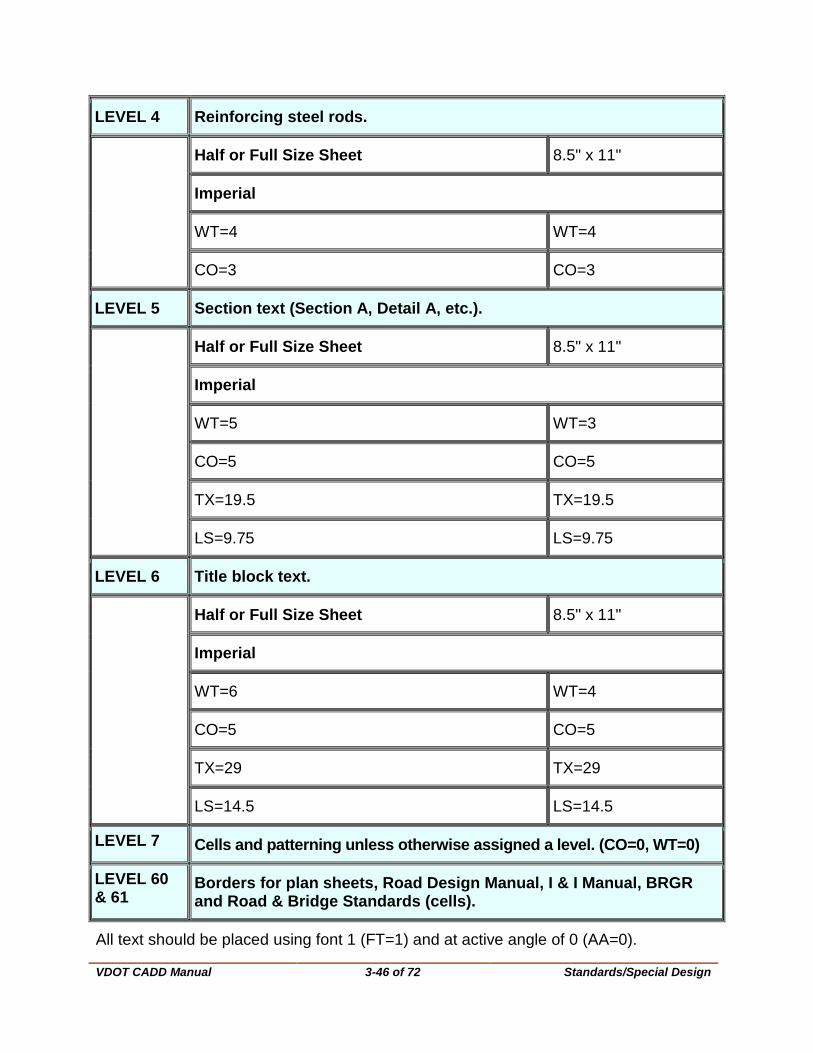
3.10.1.4 Standard Levels, Weights and Text Size for all Drawings prepared by the Standards/Special Design Section (Only)
LEVEL 1 Dimensions, extension, hidden, centerline and terminators.
Half or Full Size Sheet 8.5" x 11"
Imperial
WT=1 WT=1
CO=0 CO=0
Line terminator CO=200 Line terminator CO=200
LEVEL 2 Object elements (lines, circles, charts, etc.)
Half or Full Size Sheet 8.5 x 11
Imperial
WT=2 WT=2
CO=2 CO=2
LEVEL 3 Dimension text (over all text).
Half or Full Size Sheet 8.5" x 11"
Imperial
WT=3 WT=1
CO=1 CO=1
TX=12.5 TX=12.5
LS=6.25 LS=6.25
VDOT CADD Manual
3-46 of 72 Standards/Special Design
LEVEL 4 Reinforcing steel rods.
Half or Full Size Sheet 8.5" x 11"
Imperial
WT=4 WT=4
CO=3 CO=3
LEVEL 5 Section text (Section A, Detail A, etc.).
Half or Full Size Sheet 8.5" x 11"
Imperial
WT=5 WT=3
CO=5 CO=5
TX=19.5 TX=19.5
LS=9.75 LS=9.75
LEVEL 6 Title block text.
Half or Full Size Sheet 8.5" x 11"
Imperial
WT=6 WT=4
CO=5 CO=5
TX=29 TX=29
LS=14.5 LS=14.5
LEVEL 7 Cells and patterning unless otherwise assigned a level. (CO=0, WT=0)
LEVEL 60 & 61
Borders for plan sheets, Road Design Manual, I & I Manual, BRGR and Road & Bridge Standards (cells).
All text should be placed using font 1 (FT=1) and at active angle of 0 (AA=0).
VDOT CADD Manual
3-47 of 72 Standards/Special Design
3.10.1.5 Insertable Sheets The creation and maintenance of all insertable sheets is the responsibility of the Standards/Special Design Section, in cooperation with the CADD Support Group. Notice of the Electronic distribution of Insertable Sheet updates will be the responsibility of the Standards/Special Design Section.
All insertable sheets are used as reference files. See Instructions for using Falcon V6 for steps on referencing files. To find appropriate file to reference, set your UPC# to Eng_ser, then set Division to insert (Imperial) or minsert (Metric); scroll through the list to find file.
Prior to submission for construction (PAC), the insertable sheets for your project should be copied into the appropriate design file with the exception of the Right of Way Data sheet (a9.dgn). This sheet should be copied into the appropriate design file at the Right of Way stage.
3.10.2 Revisions to Insertable Sheets If the insertable sheets are revised by the Standards/Special Design Section, a new set of files along with a text file explaining the revisions will be sent to the District CADD Analyst. The CADD Analyst in the district and the support group in the central office should notify the designers that a revision is forthcoming and the date it will be loaded on the system. This notification should also explain what the revisions are.
The designer must then determine if he needs to keep the old insertable sheet for his particular project or if he needs to use the revised sheet. If he wants the revised sheet, it will appear automatically. If he needs to keep the old sheet, he will have to copy it into the design file prior to the new sheets being loaded on the system.
DO NOT CHANGE THE BASE CONTENT OF THE INSERTABLE SHEET WITHOUT PERMISSION FROM THE POLICIES & PROCEDURES SECTION.
3.10.3 Referencing PDF insertable sheets to a MicroStation V8i file
With the upgrade to MicroStation V8i we now have the ability to reference adobe PDF files in lieu of embedding tiff images. This will allow the sheets to print correctly from MicrosStation V8i.
The following insertable sheets are in PDF format only and will need to be referenced as a raster file to a MicroStation file when the specific standard is required for a project:
Insertable Sheets that are in PDF format only
IIS01_04 IIS05_05 IIS10_01
IIS02_01 thru IIS02_05 IIS05_07 thru IIS05_20
IIS03_03 thru IIS03_07 IIS06_01

VDOT CADD Manual
3-48 of 72 Standards/Special Design
3.10.3.1 Instructions for referencing PDF insertable sheets to a MicroStation file:
1. Go to the eng-ser directory in Falcon DocMan (be sure that the Database: Central, Richmond, Bristol, Nova… is set to the same database that your project is in) and make sure your filter is set so that you can see both dgn files and PDF files.
2. The highlighted word document contains a listing and description for all insertable sheets
VDOT CADD Manual
3-49 of 72 Standards/Special Design
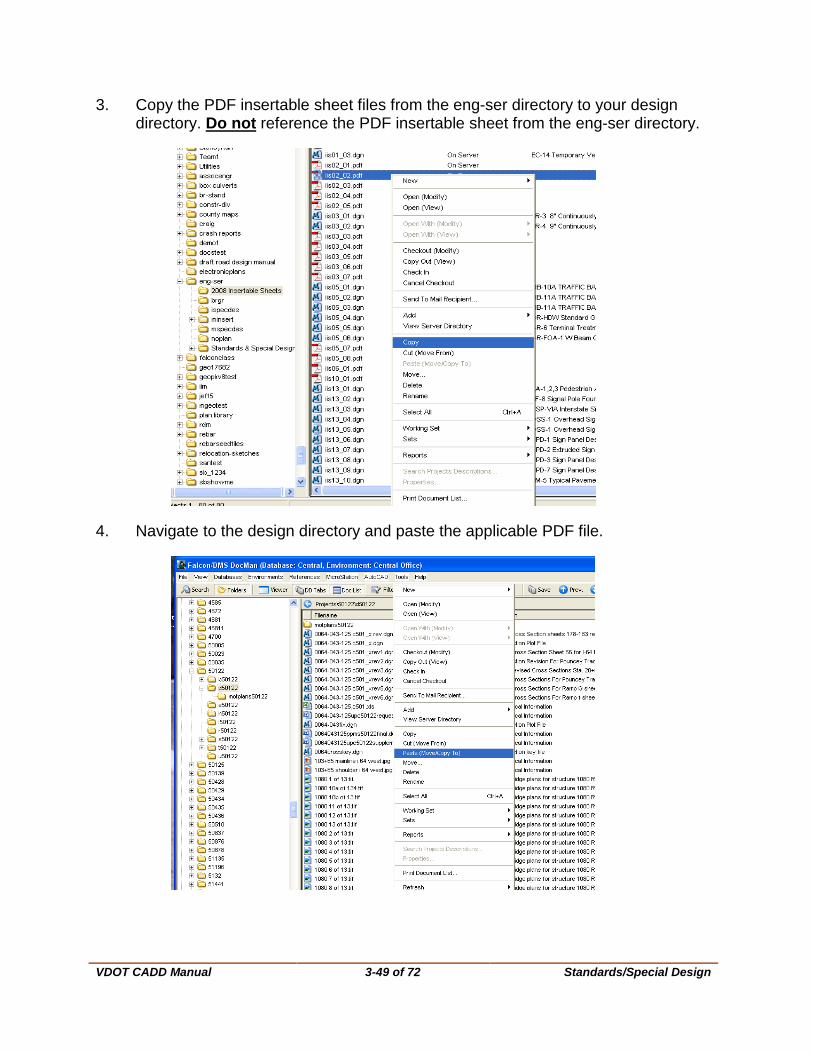
3. Copy the PDF insertable sheet files from the eng-ser directory to your design directory. Do not reference the PDF insertable sheet from the eng-ser directory.
4. Navigate to the design directory and paste the applicable PDF file.

VDOT CADD Manual
3-50 of 72 Standards/Special Design
5. You want to retain the same filename so when prompted click Ok to Keep Same Filename.
+
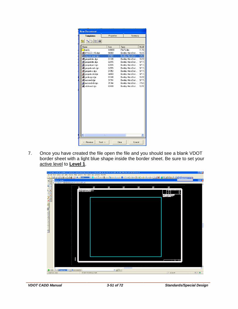
6. In your project directory, create a NEW file using the eng-ser seed.dgn file.
VDOT CADD Manual
3-51 of 72 Standards/Special Design
7. Once you have created the file open the file and you should see a blank VDOT border sheet with a light blue shape inside the border sheet. Be sure to set your active level to Level 1.
VDOT CADD Manual
3-52 of 72 Standards/Special Design
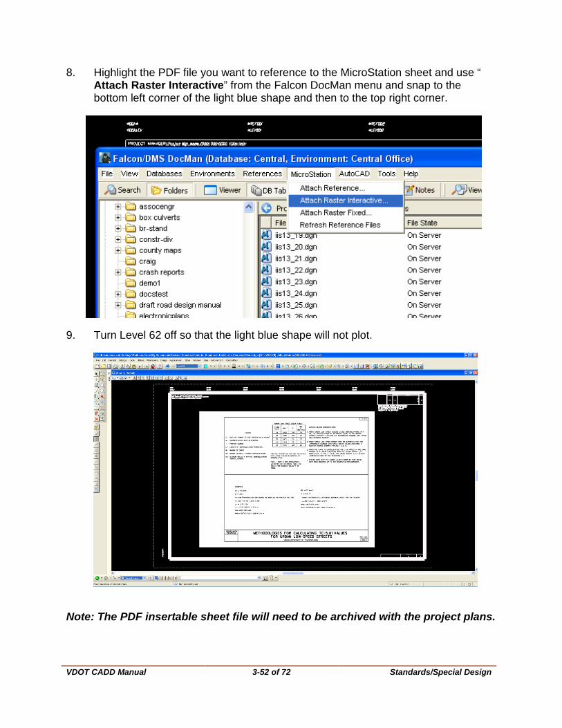
8. Highlight the PDF file you want to reference to the MicroStation sheet and use “ Attach Raster Interactive” from the Falcon DocMan menu and snap to the bottom left corner of the light blue shape and then to the top right corner.
9. Turn Level 62 off so that the light blue shape will not plot.
Note: The PDF insertable sheet file will need to be archived with the project plans.

VDOT CADD Manual
3-53 of 72 Plotting
3.11 Plotting
3.11.1 Plotting with Microstation Before plotting in MicroStation, open the Level Manager under Settings. Make sure that the appropriate levels are on/off in your design and reference files. The Plot column indicates whether elements on the level will print.
To ensure the integrity of the project, place a note in the file(s) when particular level(s) are off for plotting.
Note: The level on/off set-up for reference files does not update automatically when changes are made and settings are saved in those separate design files. If different levels need to be on/off other than when the file was initially set up, they must be toggled on/off manually, and then the settings saved to retain the new settings.
When levels are adjusted as a temporary measure, it is suggested the designer use the Save View method or close and exit the file without saving the settings. Also, be sure that the option ‘Save Settings on Exit’ is not toggled under Workspace Preferences Operation. The Default is no check mark.
3.11.1.1 Sheet sizes
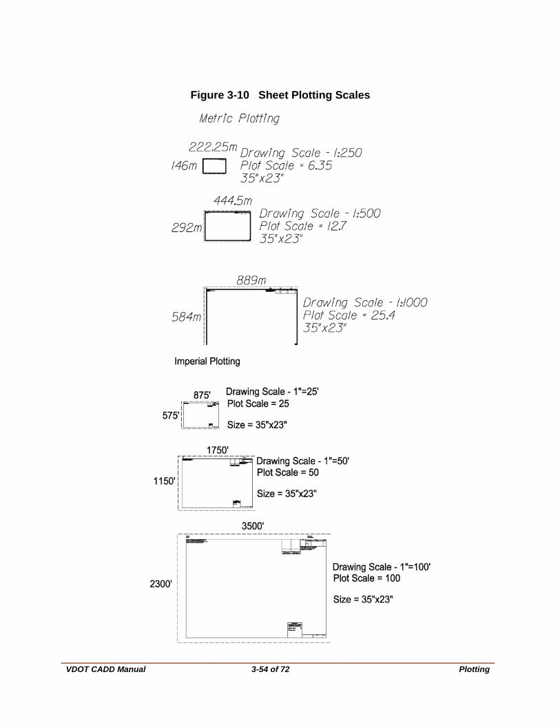
SHEET SIZE, SCALE and PLOT INFORMATION
SHEET SIZE DRAWING SCALE PLOT SCALE
Imperial Metric Imperial Metric
35”x23” 1”=25’ 1:250 25 6.35
35”x23” 1”=50’ 1:500 50 12.7
35”x23” 1”=100” 1:1000 100 25.4
VDOT CADD Manual
3-54 of 72 Plotting
Figure 3-10 Sheet Plotting Scales
VDOT CADD Manual
3-55 of 72 Plotting
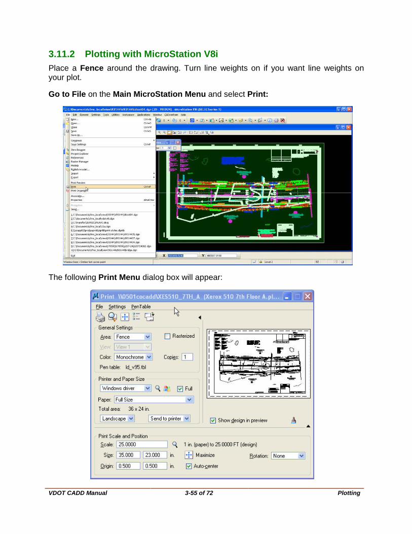
3.11.2 Plotting with MicroStation V8i Place a Fence around the drawing. Turn line weights on if you want line weights on your plot.
Go to File on the Main MicroStation Menu and select Print:
The following Print Menu dialog box will appear:
VDOT CADD Manual
3-56 of 72 Plotting
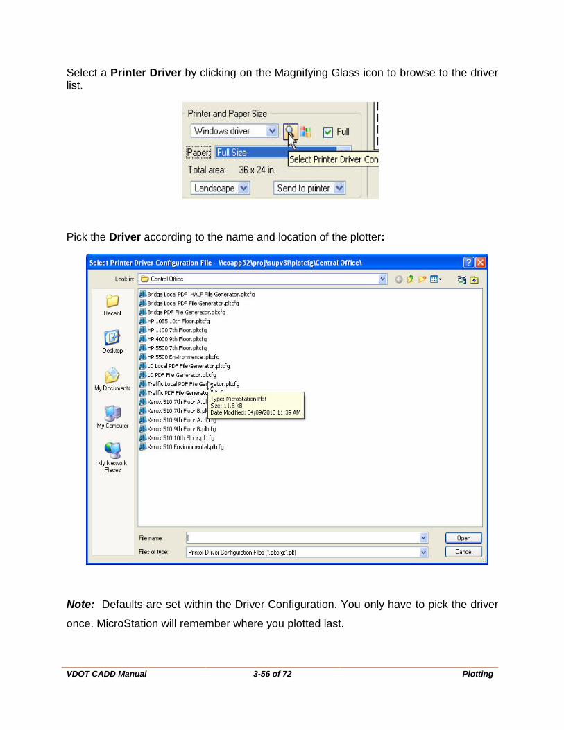
Select a Printer Driver by clicking on the Magnifying Glass icon to browse to the driver list.
Pick the Driver according to the name and location of the plotter:
Note: Defaults are set within the Driver Configuration. You only have to pick the driver
once. MicroStation will remember where you plotted last.
VDOT CADD Manual
3-57 of 72 Plotting
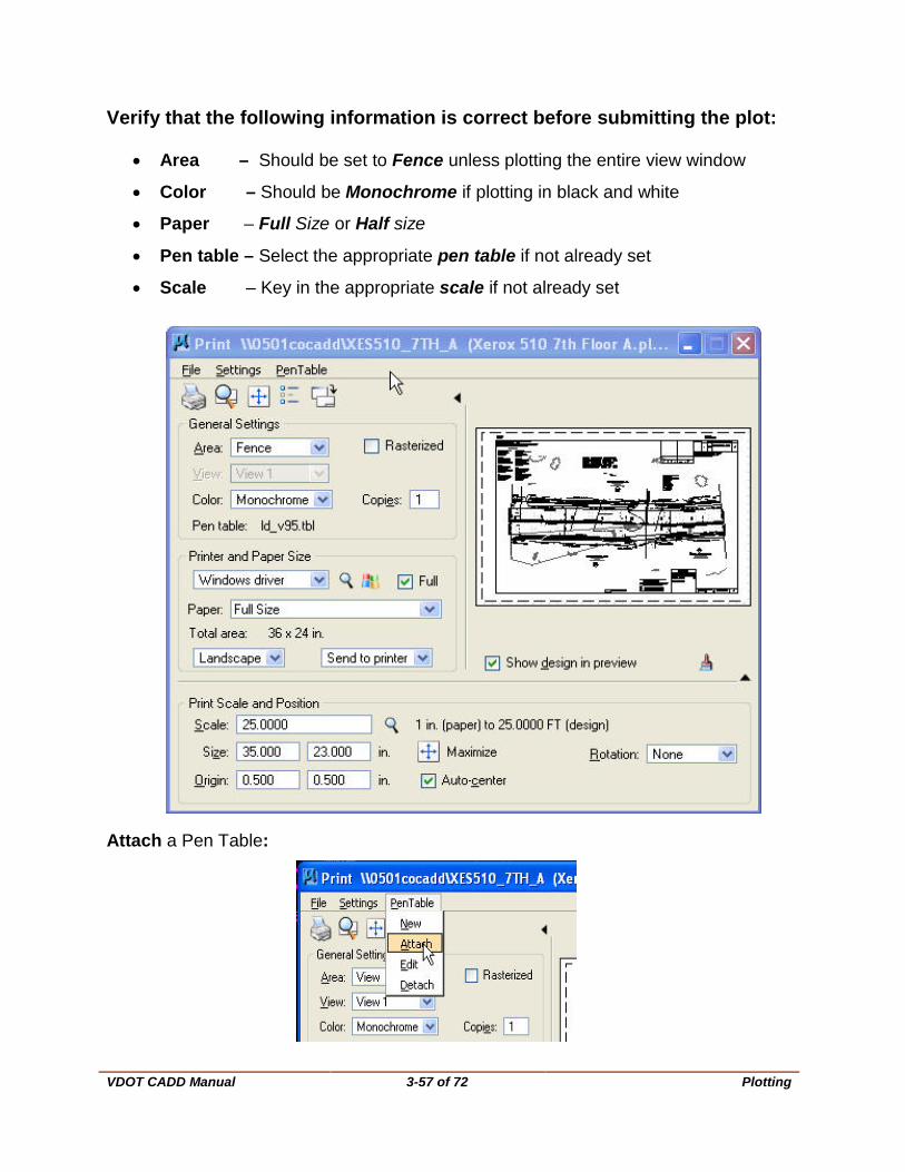
Verify that the following information is correct before submitting the plot:
• Area – Should be set to Fence unless plotting the entire view window
• Color – Should be Monochrome if plotting in black and white
• Paper – Full Size or Half size
• Pen table – Select the appropriate pen table if not already set
• Scale – Key in the appropriate scale if not already set
Attach a Pen Table:
VDOT CADD Manual
3-58 of 72 Plotting
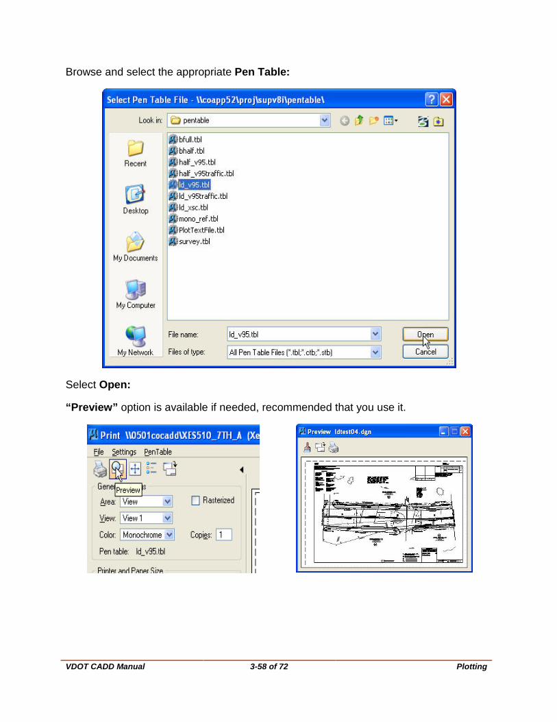
Browse and select the appropriate Pen Table:
Select Open:
“Preview” option is available if needed, recommended that you use it.
VDOT CADD Manual
3-59 of 72 Plotting
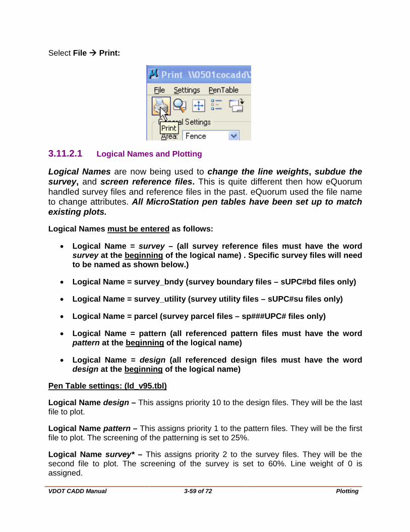
Select File Print:
3.11.2.1 Logical Names and Plotting
Logical Names are now being used to change the line weights, subdue the survey, and screen reference files. This is quite different then how eQuorum handled survey files and reference files in the past. eQuorum used the file name to change attributes. All MicroStation pen tables have been set up to match existing plots.
Logical Names must be entered as follows:
• Logical Name = survey – (all survey reference files must have the word survey at the beginning of the logical name) . Specific survey files will need to be named as shown below.)
• Logical Name = survey_bndy (survey boundary files – sUPC#bd files only)
• Logical Name = survey_utility (survey utility files – sUPC#su files only)
• Logical Name = parcel (survey parcel files – sp###UPC# files only)
• Logical Name = pattern (all referenced pattern files must have the word pattern at the beginning of the logical name)
• Logical Name = design (all referenced design files must have the word design at the beginning of the logical name)
Pen Table settings: (ld_v95.tbl)
Logical Name design – This assigns priority 10 to the design files. They will be the last file to plot.
Logical Name pattern – This assigns priority 1 to the pattern files. They will be the first file to plot. The screening of the patterning is set to 25%.
Logical Name survey* – This assigns priority 2 to the survey files. They will be the second file to plot. The screening of the survey is set to 60%. Line weight of 0 is assigned.
VDOT CADD Manual
3-60 of 72 Plotting
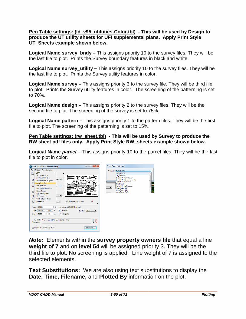
Pen Table settings: (ld_v95_utiltities-Color.tbl) - This will be used by Design to produce the UT utility sheets for UFI supplemental plans. Apply Print Style UT_Sheets example shown below.
Logical Name survey_bndy – This assigns priority 10 to the survey files. They will be the last file to plot. Prints the Survey boundary features in black and white.
Logical Name survey_utility – This assigns priority 10 to the survey files. They will be the last file to plot. Prints the Survey utility features in color.
Logical Name survey – This assigns priority 3 to the survey file. They will be third file to plot. Prints the Survey utility features in color. The screening of the patterning is set to 70%.
Logical Name design – This assigns priority 2 to the survey files. They will be the second file to plot. The screening of the survey is set to 75%.
Logical Name pattern – This assigns priority 1 to the pattern files. They will be the first file to plot. The screening of the patterning is set to 15%.
Pen Table settings: (rw_sheet.tbl) - This will be used by Survey to produce the RW sheet pdf files only. Apply Print Style RW_sheets example shown below.
Logical Name parcel – This assigns priority 10 to the parcel files. They will be the last file to plot in color.
Note: Elements within the survey property owners file that equal a line weight of 7 and on level 54 will be assigned priority 3. They will be the third file to plot. No screening is applied. Line weight of 7 is assigned to the selected elements.
Text Substitutions: We are also using text substitutions to display the Date, Time, Filename, and Plotted By information on the plot.
VDOT CADD Manual
3-61 of 72 Plotting
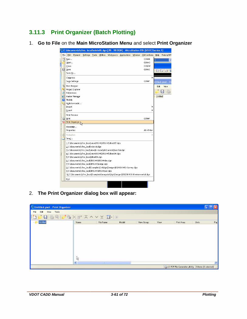
3.11.3 Print Organizer (Batch Plotting)
1. Go to File on the Main MicroStation Menu and select Print Organizer
2. The Print Organizer dialog box will appear:

VDOT CADD Manual
3-62 of 72 Plotting
3. Go to File Add Files to Set 4. Select Add:
5. Then Browse to the files. Select the files and click Done.
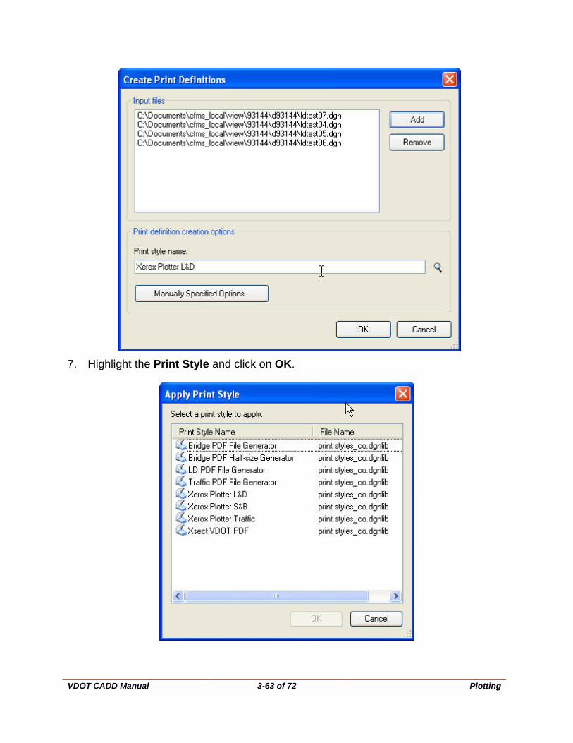
6. Choose the Print Style Name next by selecting the Magnifying glass:
VDOT CADD Manual
3-63 of 72 Plotting
7. Highlight the Print Style and click on OK.
VDOT CADD Manual
3-64 of 72 Plotting
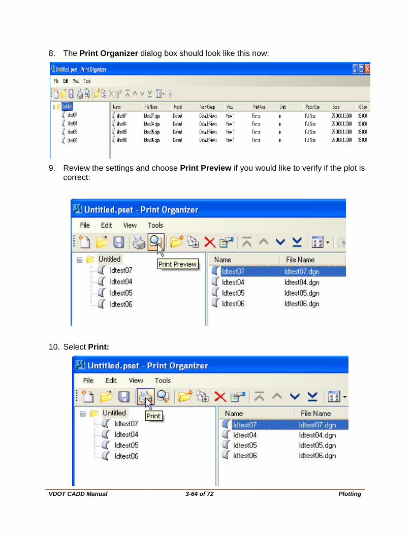
8. The Print Organizer dialog box should look like this now:
9. Review the settings and choose Print Preview if you would like to verify if the plot is
correct:
10. Select Print:

VDOT CADD Manual
3-65 of 72 Plotting
11. The following Print Dialog box should appear. Select Printer Setup.
12. The following Printer Setup dialog box should appear:
Choose the correct Driver Configuration File and Windows Printer Name (Printer should default correctly, if not choose the Printer)
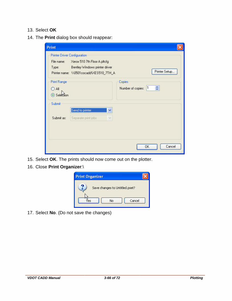
VDOT CADD Manual
3-66 of 72 Plotting
13. Select OK 14. The Print dialog box should reappear:
15. Select OK. The prints should now come out on the plotter. 16. Close Print Organizer:\
17. Select No. (Do not save the changes)
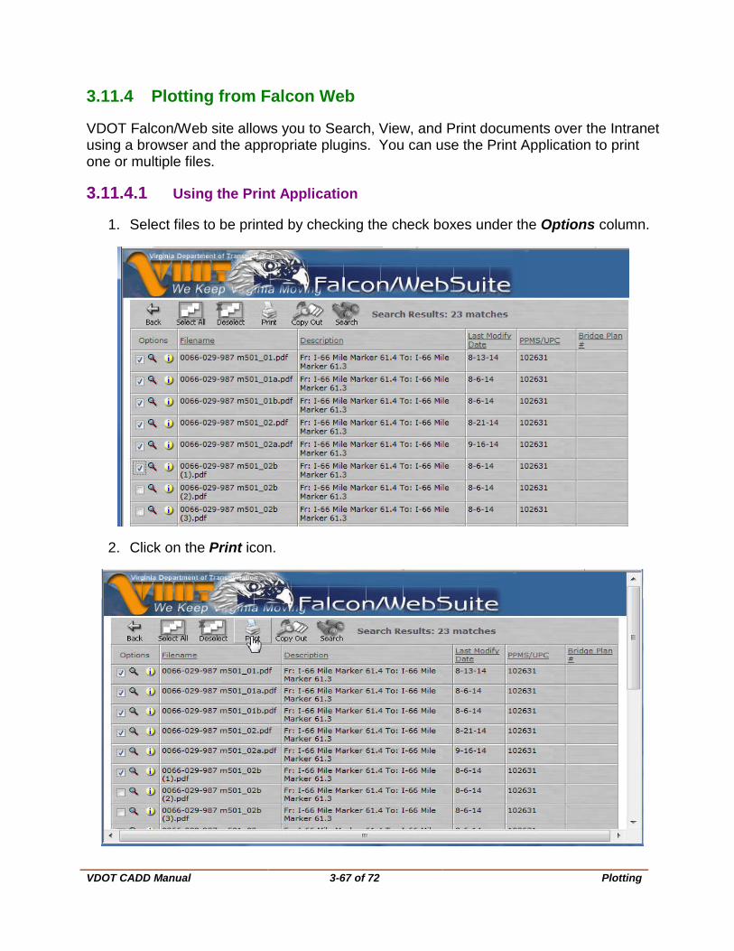
VDOT CADD Manual
3-67 of 72 Plotting
3.11.4 Plotting from Falcon Web
VDOT Falcon/Web site allows you to Search, View, and Print documents over the Intranet using a browser and the appropriate plugins. You can use the Print Application to print one or multiple files.
3.11.4.1 Using the Print Application
1. Select files to be printed by checking the check boxes under the Options column.
2. Click on the Print icon.

VDOT CADD Manual
3-68 of 72 Plotting
3. Click on the “Reverse standard print order” check box so plan sheets will come out in the correct order.
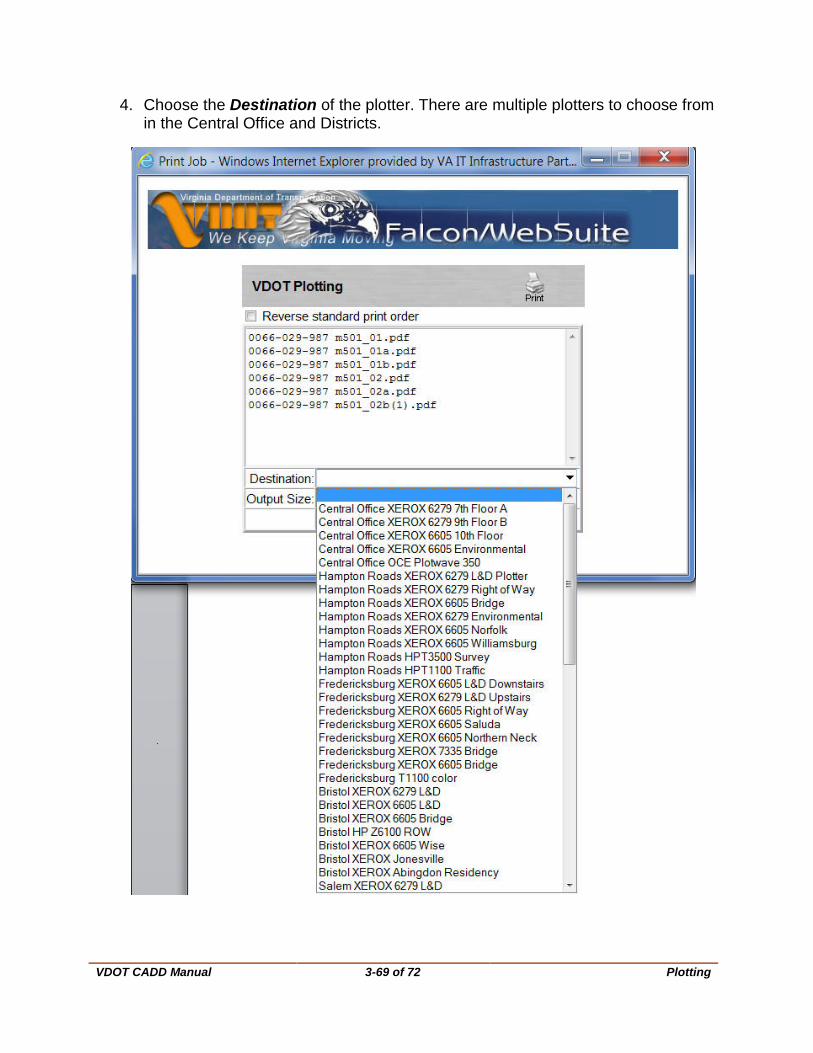
VDOT CADD Manual
3-69 of 72 Plotting
4. Choose the Destination of the plotter. There are multiple plotters to choose from in the Central Office and Districts.
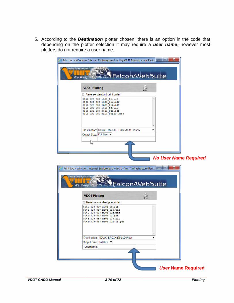
VDOT CADD Manual
3-70 of 72 Plotting
5. According to the Destination plotter chosen, there is an option in the code that depending on the plotter selection it may require a user name, however most plotters do not require a user name.
No User Name Required
User Name Required
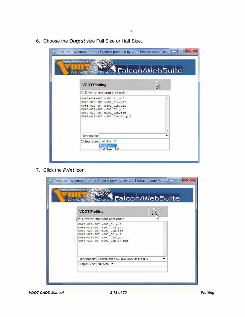
VDOT CADD Manual
3-71 of 72 Plotting
+
6. Choose the Output size Full Size or Half Size..
7. Click the Print Icon.
VDOT CADD Manual
3-72 of 72 Plotting
8. Prints have been sent to the plotter. Click on the Close button to exit.


![capseguridad_uv2- DGN[2]](https://static.fdocuments.us/doc/165x107/55cf8e5f550346703b91701b/capseguridaduv2-dgn2.jpg)