CHAPTER 3 DESCRIPTION AND COMPARISON OF ALTERNATIVES
131
FINAL ENVIRONMENTAL IMPACT STATEMENT Brightwater Regional Wastewater Treatment System VOLUME 1 CHAPTER 3 DESCRIPTION AND COMPARISON OF ALTERNATIVES 3. DESCRIPTION AND COMPARISON OF ALTERNATIVES
Transcript of CHAPTER 3 DESCRIPTION AND COMPARISON OF ALTERNATIVES
FINALENVIRONMENTALIMPACT STATEMENT
BrightwaterRegional WastewaterTreatment System
VOLUME 1
CHAPTER 3DESCRIPTION AND
COMPARISON OF ALTERNATIVES
3. D
ESCRIPTIO
NA
ND
CO
MPA
RISON
OF
ALTERN
ATIVES
Chapter 3. Description and Comparison of Alternatives Contents
Contents
Chapter 3 Description and Comparison of Alternatives ......................................... 3-1 3.1 Introduction.................................................................................................... 3-1
3.1.1 Project Objectives .............................................................................. 3-1 3.1.2 Refinements of the Proposal Since the Draft EIS.............................. 3-3
3.1.2.1 Refinements Common to All Systems................................... 3-3 Treatment Plant Common to All Systems .................................................. 3-3 Conveyance System Common to All Systems ........................................... 3-3 Outfall Common to All Systems ................................................................ 3-4
3.1.2.2 Refinements to the Route 9–195th and 228th Street Systems .................................................................................. 3-5
Treatment Plant: Route 9 Systems.............................................................. 3-5 Conveyance System: Route 9 Systems....................................................... 3-6 Outfall: Route 9 Systems............................................................................ 3-7
3.1.2.3 Unocal System ....................................................................... 3-7 Treatment Plant: Unocal............................................................................. 3-7 Conveyance System: Unocal ...................................................................... 3-8 Outfall: Unocal ........................................................................................... 3-8
3.2 Action Alternatives ........................................................................................ 3-8 3.2.1 Elements Common to All Action Alternatives .................................. 3-9
3.2.1.1 Treatment Processes Common to All Action Alternatives ............................................................................ 3-9
Plant Layout, Capacity, and Liquids Process ............................................. 3-9 Solids Processing and Biosolids Management ......................................... 3-11 Water Reuse.............................................................................................. 3-12
3.2.1.2 Odor Control Common to All Action Alternatives ............. 3-13 3.2.1.3 Other Onsite Facilities Common to All Action
Alternatives .......................................................................... 3-14 Influent Pump Station (IPS) ..................................................................... 3-14 Administration Building........................................................................... 3-14 Maintenance Building .............................................................................. 3-14 Chemical Building.................................................................................... 3-14 Cogeneration Facility ............................................................................... 3-15
3.2.1.4 Operation Characteristics Common to All Action Alternatives .......................................................................... 3-15
Hours of Operation and Staffing .............................................................. 3-15 Truck Trips During Operation.................................................................. 3-16 Energy Usage............................................................................................ 3-16
3.2.1.5 Conveyance System Common to All Action Alternatives .......................................................................... 3-16
System Overview...................................................................................... 3-16 Pipelines and Tunnels............................................................................... 3-18 Primary Portals ......................................................................................... 3-19 Secondary Portals ..................................................................................... 3-19 Permanent Facilities ................................................................................. 3-20
3.2.1.6 Connections to Existing Systems Common to All Action Alternatives .............................................................. 3-20
Brightwater Final EIS i
Chapter 3. Description and Comparison of Alternatives Contents
Kenmore Pump Station Connection ......................................................... 3-20 Kenmore Local Sewer System Connection .............................................. 3-21 Swamp Creek Trunk Connection ............................................................. 3-21 North Creek Pump Station Connection .................................................... 3-21
3.2.1.7 Outfall Common to All Action Alternatives........................ 3-22 3.2.1.8 Conveyance Safety Relief Point Common to All Action
Alternatives .......................................................................... 3-23 3.2.1.9 Construction Activities and Schedule Common to All
Action Alternatives .............................................................. 3-24 Construction Activities ............................................................................. 3-24 Construction Schedule.............................................................................. 3-24
3.2.2 Route 9–195th Street System........................................................... 3-25 3.2.2.1 Treatment Plant: Route 9–195th Street System................... 3-25
Site Location and Layout.......................................................................... 3-25 Construction Schedule.............................................................................. 3-29
3.2.2.2 Conveyance System: Route 9–195th Street System ............ 3-31 Influent Pipeline ....................................................................................... 3-31 Effluent Pipeline....................................................................................... 3-32 Portal Siting Areas.................................................................................... 3-35 Portal 41 Influent Pump Station Option ................................................... 3-36 Construction Schedule.............................................................................. 3-37
3.2.2.3 Outfall: Route 9–195th Street System ................................. 3-37 3.2.3 Route 9–228th Street System........................................................... 3-38
3.2.3.1 Treatment Plant: Route 9–228th Street System................... 3-38 3.2.3.2 Conveyance System: Route 9–228th Street System ............ 3-38
Influent Pipeline ....................................................................................... 3-39 Effluent Pipeline....................................................................................... 3-39 Portal Siting Areas.................................................................................... 3-39 Construction Schedule.............................................................................. 3-40
3.2.3.3 Outfall: Route 9–228th Street System ................................. 3-40 3.2.4 Unocal System ................................................................................. 3-44
3.2.4.1 Treatment Plant: Unocal System ......................................... 3-44 Site Location and Layout.......................................................................... 3-44 Sub-Alternatives ....................................................................................... 3-50 Construction Schedule.............................................................................. 3-52
3.2.4.2 Conveyance System: Unocal System................................... 3-52 Influent Pipeline ....................................................................................... 3-53 Portal Siting Areas.................................................................................... 3-53 New Kenmore Pump Station .................................................................... 3-55 Construction Schedule.............................................................................. 3-55
3.2.4.3 Outfall: Unocal System........................................................ 3-56 3.2.5 No Action Alternative...................................................................... 3-57
3.3 Comparing the Alternatives ......................................................................... 3-58 3.3.1 Overall Comparison of Impacts for Alternative Components and
Systems ............................................................................................ 3-62 3.3.1.1 Treatment Plant Sites ........................................................... 3-62
Route 9 Site .............................................................................................. 3-63 Unocal Site ............................................................................................... 3-64
3.3.1.2 Conveyance Corridors ......................................................... 3-65
Brightwater Final EIS ii

Chapter 3. Description and Comparison of Alternatives Contents
3.3.1.3 Outfalls................................................................................. 3-66 3.3.2 Comparison of Environmental Impacts by Element of the
Environment........................................................................ 3-67 3.3.2.1 Earth..................................................................................... 3-67 3.3.2.2 Air ........................................................................................ 3-69 3.3.2.3 Water Resources .................................................................. 3-70
Groundwater ............................................................................................. 3-70 Surface Water ........................................................................................... 3-72
3.3.2.4 Plants, Animals, and Wetlands ............................................ 3-73 3.3.2.5 Energy .................................................................................. 3-74 3.3.2.6 Environmental Health .......................................................... 3-75 3.3.2.7 Noise and Vibration ............................................................. 3-75 3.3.2.8 Land and Shoreline Use ....................................................... 3-76 3.3.2.9 Aesthetics............................................................................. 3-77 3.3.2.10 Light and Glare .................................................................... 3-78 3.3.2.11 Recreation ............................................................................ 3-78 3.3.2.12 Cultural Resources ............................................................... 3-79 3.3.2.13 Transportation ...................................................................... 3-80 3.3.2.14 Public Services and Utilities ................................................ 3-81
3.3.3 Summary of Impacts for Alternative Systems ................................. 3-81 3.3.4 Summary of Mitigation Measures ................................................... 3-82
3.4 References.................................................................................................... 3-83 List of Tables
Table 3-1. Brightwater Treatment Plant Design Capacity ......................................................... 3-10 Table 3-2. Overview of Route 9 Treatment Facilities and Construction Schedule ................... 3-29 Table 3-3. Overview of Route 9–195th Street Conveyance System Primary Portals ................ 3-33 Table 3-4. Overview of Route 9–195th Street Conveyance System Secondary Portals ........... 3-35 Table 3-5. Permanent Conveyance Facilities, 195th Street Corridor ......................................... 3-36 Table 3-6. Brightwater Outfall Characteristics for Route 9 Alternatives................................... 3-38 Table 3-7. Overview of Route 9–228th Street Conveyance System .......................................... 3-41 Table 3-8. Overview of Route 9–228th Street Conveyance System Secondary Portals ........... 3-43 Table 3-9. Permanent Conveyance Facilities, 228th Street Corridor ......................................... 3-43 Table 3-10. Overview of Unocal Treatment Facilities ............................................................... 3-45 Table 3-11. Overview of Unocal Conveyance System............................................................... 3-54 Table 3-12. Overview of Unocal Conveyance System Secondary Portals................................. 3-55 Table 3-13. Permanent Conveyance Facilities, Unocal Corridor ............................................... 3-56 Table 3-14. Brightwater Outfall Characteristics for Unocal Alternative ................................... 3-57 Table 3-15. Comparison of Key Features of the Brightwater Alternatives ................................ 3-59
Brightwater Final EIS iii
Chapter 3 Description and Comparison of
Alternatives
3.1 Introduction Chapter 2 described the evaluation and screening process that led to the development of the alternatives that are currently under consideration for the Brightwater Regional Wastewater Treatment System. This chapter provides more detailed information about the three action alternatives evaluated in this Final EIS: the Route 9–195th Street System, the Route 9–228th Street System, and the Unocal System. (These alternatives are depicted in the large System Alternatives map on the inside of the back cover of this volume.) The No Action Alternative is also described. At the end of the chapter, the three action alternatives are compared. The No Action Alternative is addressed in detail under each SEPA element of the environment in Chapters 4 through 17, where side-by-side impact comparisons are also provided at chapter end. This chapter also includes a discussion of the project objectives and describes refinements to the proposal that have occurred since publication of the Draft EIS.
3.1.1 Project Objectives The primary objective for the Brightwater project is to implement the regional policy mandate, contained in the Regional Wastewater Services Plan (RWSP), to construct a new treatment plant to address future treatment needs. Policy TPP-2 of the adopted plan states:
King County shall provide additional wastewater treatment capacity to serve growing wastewater needs by constructing a new north treatment plant in north King County or south Snohomish County and then expanding the treatment capacity at the south treatment plant. The west treatment plant shall be maintained at its rated capacity of one hundred thirty-three million gallons per day (mgd). The south treatment plant capacity shall be limited to that needed to serve the eastside and south King County, except for flows from the North Creek Diversion project and the planned six-million-gallon storage tank. The potential for expansion at the west treatment plant and south treatment plant should be retained for unexpected circumstances which shall include, but not be
Brightwater Final EIS 3-1
Chapter 3. Description and Comparison of Alternatives
limited to, higher than anticipated population growth, new facilities to implement the CSO reduction program or new regulatory requirements.
The RWSP is intended to protect human health and the environment by providing high quality wastewater conveyance and treatment services to this region. Other objectives for the Brightwater project include the following:
• Accommodate projected average and peak wastewater flows from the service area
• Produce treated effluent that uses secondary treatment consistent with the Clean Water Act and that meets Washington State Water Quality Standards for discharge to Puget Sound
• Produce reclaimed water for reuse on- and offsite
• Produce biosolids suitable for beneficial reuse and recycling, including application to agricultural and forestry lands, or for use in composting
• Provide flexibility for rerouting flows within the conveyance system to King County’s other two regional wastewater treatment plants—the West Point Treatment Plant in Seattle and the South Treatment Plant in Renton
• Provide additional wastewater storage to reduce peak flows to the treatment plant and/or to accommodate routine and emergency conveyance system maintenance and operation
The EIS for the RWSP (King County, 1998) is adopted herein by reference, and addresses the environmental impacts of meeting RWSP objectives.
The general proposal identified in the 1999 RWSP was subsequently refined by the King County Council in 2000 and 2001. The Council adopted two sets of policy siting criteria in Ordinance 14043 and Ordinance 14107. SEPA review was conducted prior to the Council's adoption of each ordinance. In these ordinances the Council narrowed, based on environmental review and policy considerations, potential sites for the proposed system facilities that would go forward for more detailed environmental review in the Brightwater EIS. The Council took into account environmental, engineering, community, and other policy considerations in developing the proposal. Based on the Council's adoption of policy criteria and development of the proposal that would go forward into the Brightwater EIS, Executive Sims selected two treatment plant sites that were deemed to meet the policy criteria.
At the end of 2001, the Brightwater proposal, as refined by the Council, went forward into EIS scoping and preparation of the Draft EIS.
3-2 Brightwater Final EIS

Chapter 3. Description and Comparison of Alternatives
3.1.2 Refinements of the Proposal Since the Draft EIS After publication of the Draft EIS, King County continued to refine the Brightwater System alternatives to reduce impacts, increase system efficiency, and enhance consistency with the objectives discussed above. All of these refinements fall within the range of alternatives evaluated in the Draft EIS. Many of the refinements were developed in response to Draft EIS comments and are intended to provide enhanced mitigation of the proposal. This section summarizes the proposed refinements and the key reasons for each. More detailed information on each refinement can be found under the descriptions of the three action alternatives later in this chapter.
3.1.2.1 Refinements Common to All Systems
Treatment Plant Common to All Systems
• Membrane bioreactor technology. In the Draft EIS, a conservatively sized conventional activated sludge (CAS) process was considered. In comparing alternatives for secondary treatment, it was recognized that the membrane bioreactor (MBR) technology process would substantially lower discharge of pollutants to Puget Sound when compared to CAS. The process also would occupy less land than conventional activated sludge, thereby increasing the area available for mitigation and environmental enhancement. The MBR process would treat wastewater flows up to the average wet weather flow (AWWF). Peak flows above this level would be treated using a ballasted sedimentation process, then blended with the MBR effluent prior to discharge. This “split-flow” approach provides the water quality benefits of MBR technology, but is more cost-effective than using MBR for peak flows.
• Filtration. The Draft EIS included facilities for effluent filtration for water reuse using granular filtration of CAS effluent. Since CAS is no longer proposed, this would not be needed because MBR produces filtered effluent and no additional filtration is required to produce Class A reclaimed water. However, an additional process, disinfection, is required to produce reclaimed water from the MBR effluent.
Conveyance System Common to All Systems
• Refinement of portal location and design. Since the Draft EIS, the portal siting areas (PSAs) identified in the Draft EIS have been specified as primary and secondary for each conveyance alignment. Primary portals would be required to make tunnel construction feasible for drive lengths (distances between portals) of up to approximately 20,000 feet and are located along each corridor at this approximate interval. Additionally, activities that would take place at the primary
Brightwater Final EIS 3-3
Chapter 3. Description and Comparison of Alternatives
portals have been defined in more detail in the Final EIS. Secondary portal sites are not expected to be used based on current information and engineering. However, as more geotechnical analysis is performed during final design, it may prove necessary to use one or more secondary portals. A decision on the need for secondary portals will not be made until final design is completed. If needed, secondary portals may be used for temporary ventilation, ground improvement, and/or supplying grout to the tunnel. Secondary portals would be a much smaller diameter than primary portals, require less land area (one-half acre or less), and support less intensive construction activities. If required, secondary portals would be located within approximately 10,000 feet of a primary or another secondary portal.
• Candidate portal sites. Two to six portal candidate sites have been identified within each PSA. Smaller sites, ranging from approximately 2 to 16 acres, have been identified within the 72-acre PSAs to allow for more detailed assessment of potential impacts.
• Pump station locations. The need for pump stations has changed since publication of the Draft EIS. For the Route 9 system alternatives, the effluent pump station located on the Route 9 site has been eliminated. These alternatives now include only an influent pump station at the Route 9 site, or potentially at Portal 41. The Unocal system includes both influent and effluent pump stations at the plant site and a new Kenmore Pump Station (influent) at PSA 11, as described in the Draft EIS.
• Tunnel profile. The tunnel profile was optimized and overall depth was reduced.
• Portal depths. Refinements in design have allowed specific portal depths to be identified in the Final EIS, rather than the wide range shown in the Draft EIS.
• Odor control. Specific odor control facilities and technologies have been identified and are designated to be located at some of the primary portals.
• Duration of construction. Specific construction duration has been identified at each primary portal location.
• Dewatering rates and discharge locations. Dewatering rates and potential discharge locations have been identified for each primary portal.
Outfall Common to All Systems
• Preferred construction method. Open-cut construction onshore and through the nearshore area has been identified as the preferred construction method (as opposed to tunneling (specifically, microtunneling), which was the method preferred in the Draft EIS).
• Identification of preferred outfall alignments. Preferred alignments have been identified in both Zone 7S (Route 9) and Zone 6 (Unocal).
3-4 Brightwater Final EIS
Chapter 3. Description and Comparison of Alternatives
• Selection of diffuser length. A diffuser length of 500 feet has been identified to meet hydraulic and dilution goals for all alternatives.
3.1.2.2 Refinements to the Route 9–195th and 228th Street Systems
Treatment Plant: Route 9 Systems
• Odor control process. In the Draft EIS, the proposed odor control system was three-stage chemical scrubbers followed by biofilters for polishing at the Route 9 site. The system currently proposed consists of three-stage chemical scrubbers plus carbon polishing for both treatment plant sites. The odor control system described in the Draft EIS for Route 9 had all process air routed to one central location for treatment. It is now decentralized (process air treated adjacent to the facility where it originates).
• Wastewater flow direction. In the Draft EIS, the influent pump station was located at the north end of the site and the wastewater flowed from north to south through the treatment process units. This arrangement has been reversed so that the influent pump station would be located at the south end of the site and the wastewater would flow from south to north. This would allow for a shorter influent tunnel.
• Effluent pump station eliminated. It was determined during predesign that an effluent pump station for the Route 9 site would not be required, and it has been eliminated from the project as proposed in the Draft EIS.
• StockPot, Inc., property included. In the Draft EIS, the StockPot property was excluded from the plant site design. The current layout assumes that StockPot would move offsite and the land it occupied would be available for treatment plant facilities.
• Water resource management. The Draft EIS layout included collection of stormwater at the lowest part of the site and a pump station to pump it to a higher elevation in the northern portion of the site for detention and treatment. In the current design, detention and treatment would be provided along the western part of the site; after treatment, stormwater would flow by gravity through the system of existing culverts under Route 9 and into Little Bear Creek. One or more of these culverts may require reconstruction to achieve the required capacity. The revised approach minimizes impacts to forested and wetland areas of the site, provides an enhanced visual buffer for the site, and reduces energy use by eliminating the stormwater pump station.
• Potential onsite Community-Oriented Building. The revised layout includes space onsite for an additional building for community and educational uses should the community desire such a facility. This building could be a potential mitigation
Brightwater Final EIS 3-5

Chapter 3. Description and Comparison of Alternatives
measure for loss of a community meeting space as a result of eliminating the existing Grange Hall. The onsite Community-Oriented Building was not included in the Draft EIS.
Conveyance System: Route 9 Systems
Route 9–195th and 228th Street Systems
• PSA 10 and the tunnel from PSA 10 to PSA 11. PSA 10 and the tunnel from PSA 10 to PSA 11 have been eliminated from the Route 9 alternatives. The flows from the McAleer/Lyon sewer trunk line will continue to be routed to West Point for treatment, eliminating the need for a tunnel from Portal 10 to 11 until at least several decades. A smaller, local connection from the existing conveyance system to the Brightwater conveyance system, when needed for flow management reasons, would be made using open cut or microtunneling construction methods. The local connection included in the Brightwater proposal would be in Kenmore from approximately 61st Avenue NE along NE 175th Street to PSA 11. The main influent tunnel is now proposed to begin at Portal 11.
• Tunnel alignment. The tunnel alignment has been revised for the Route 9 influent tunnel to minimize the number of private properties the tunnel would cross underneath. The alignment follows street rights-of-way wherever possible. PSA 34 was eliminated from the conveyance system because the influent tunnel alignment was refined such that it no longer passes through PSA 34.
• Portal 41 influent pump station (IPS) option. King County is continuing to explore methods to mitigate impacts and improve operational efficiencies. Eliminating the IPS at the Route 9 treatment plant site and relocating it to PSA 41 is one option currently being investigated. One major advantage of relocating the influent pump station to PSA 41 is that it would reduce the depth of the IPS from approximately 300 feet to less than 100 feet, which would provide various constructibility, environmental, operational, and financial benefits. A decision to relocate the IPS to Portal 41 would not be made until after issuance of the Final EIS and selection of a specific Brightwater System. The environmental impacts and benefits of relocating the IPS to PSA 41 are discussed in relevant sections throughout this EIS under “Portal 41 Influent Pump Station Option.” For a more detailed description of this option, see the description of the Route 9–195th Street System below.
Route 9–195th System Only
• Portal 5. Portal 5 has been added to the Route 9–195th alignment. Portal 5 is a secondary portal under the Unocal alternative. It was added to the Route 9–195th Street alignment as a primary portal when PSA 7 and PSA 27 were identified as secondary portals due to a decision to design the conveyance system with lengthened tunnel drives of approximately 20,000 feet.
3-6 Brightwater Final EIS

Chapter 3. Description and Comparison of Alternatives
• Tunnel alignment. The realignment of the Route 9 influent tunnel takes advantage of the opportunity to minimize construction impacts of the 195th Street conveyance alternative by combining influent and effluent lines in one larger diameter tunnel for more than 4 miles for the Route 9–195th Street System.
Outfall: Route 9 Systems
• Same as common to all systems.
3.1.2.3 Unocal System
Treatment Plant: Unocal
• Effluent disinfection. The Draft EIS included ultraviolet (UV) light for disinfecting secondary effluent and water for reuse. Due to the change to a split-flow MBR system, UV light is proposed for the MBR portion of the effluent only. The remaining portion of the split flow, that portion that would receive treatment in the ballasted sedimentation process, would undergo sodium hypochlorite disinfection. The water reuse system would use UV for disinfection as described in the Draft EIS.
• Stormwater discharge. The wet pond system described in the Draft EIS would remain the same. However, instead of discharging the treated stormwater through the treatment plant’s effluent outfall, the stormwater would be discharged through a separate, much smaller outfall at elevation –50 mean lower low water (MLLW). (See Outfall section below.)
• Unocal site lid. In the Draft EIS, a sub-alternative for the Unocal site included construction of a lid over the treatment plant facilities for potential future development of this site either as a multimodal transportation facility (Edmonds Crossing, a use currently proposed by the Washington State Department of Transportation, the Federal Highway Administration, and the City of Edmonds) or a landscaped park for public access. The Final EIS considers the lid only for the multimodal facility; a park is no longer proposed.
• Unocal barge dock. The Draft EIS considered using a barge dock for construction of the treatment plant at the Unocal site. Use of a barge dock is no longer included as part of the proposal analyzed in the Final EIS. Comments received on the Draft EIS highlighted potential significant impacts to the marine environment if the dock were used. However, use of the dock may still be considered in the future as a traffic mitigation measure, if warranted, in which case appropriate environmental review would be conducted.
Brightwater Final EIS 3-7

Chapter 3. Description and Comparison of Alternatives
Conveyance System: Unocal
• Unocal Conveyance System. Instead of the two conveyance elevation options for the Unocal conveyance system presented in the Draft EIS, only the shallower depth conveyance option, which included force mains, has been considered as part of the Final EIS. The current proposed conveyance would be a gravity system between Portal 14 and Portal 11. A new pump station near the existing Kenmore Pump Station at Portal 11 would be required to pump the wastewater uphill to Portal 7. The tunnel would be constructed at a grade that roughly follows the ground surface between Portals 11 and 7, thereby minimizing the required depths for the portals. Force mains would be installed within the tunnel between Portal 11 and Portal 7. The conveyance system would convert back to a gravity system between Portal 7 and the Unocal site. An influent and effluent pump station would still be required on the Unocal site.
Outfall: Unocal
• Same as common to all systems.
3.2 Action Alternatives The principal features of the Brightwater System called for in the RWSP include a new secondary treatment plant; the associated pipelines, pump stations, and other facilities that make up the conveyance system to transport wastewater to and from the plant; and an outfall to discharge effluent to Puget Sound. The RWSP places special emphasis on the need to have this new wastewater system operational by 2010. (See Chapter 2 for a discussion of population and flow analysis that drives the project schedule.)
Three action alternatives have been identified for meeting future treatment needs. Each is evaluated in this EIS as a complete system that includes wastewater treatment, conveyance, and outfall as well as associated facilities. The three action alternatives are as follows:
• Route 9–195th Street System (Preferred Alternative)
• Route 9–228th Street System
• Unocal System
Each of these systems is described in this section, with a focus on those features of the systems that are most relevant to the analysis of environmental impacts. The section begins with a description of the features that are common to all the action alternatives, followed by discussions of features specific to each of the action alternatives. The No Action Alternative, as required by SEPA, is used in the EIS as a baseline against which to assess the impacts of the action alternatives. The No Action Alternative is included in
3-8 Brightwater Final EIS

Chapter 3. Description and Comparison of Alternatives
each chapter and compared alongside each of the action alternatives in detail under each element of the environment. More detailed information on the action alternatives, including technical characteristics of the treatment processes and other system features, can be found in Appendix 3-A, Project Description: Treatment Plant; Appendix 3-B, Project Description: Conveyance; and Appendix 3-C, Project Description: Outfall. Appendix 3-J, Evaluation of the No Action Alternative, provides details on the No Action Alternative.
3.2.1 Elements Common to All Action Alternatives This section describes features of the Brightwater treatment, conveyance, and outfall systems common to all the action alternatives. For readers not familiar with the basics of wastewater treatment, an overview is provided in Chapter 2.
3.2.1.1 Treatment Processes Common to All Action Alternatives
Plant Layout, Capacity, and Liquids Process
Buildings and equipment at each site would be arranged in a manner that would support an efficient treatment process flow. Overall site layout, however, would differ substantially between the Route 9 and Unocal sites because of differences in the location, topography, soils, size, and shape of the sites. Each of the plant layouts was developed to include space for future expansion to 54 million gallons per day (mgd) average wet-weather flow. Space is also provided to convert the membrane bioreactor technology to a conventional activated sludge process that uses secondary clarifiers, if needed in the future. Additional space has also been reserved if King County elects to produce Class A biosolids and/or 54 mgd of reclaimed water.
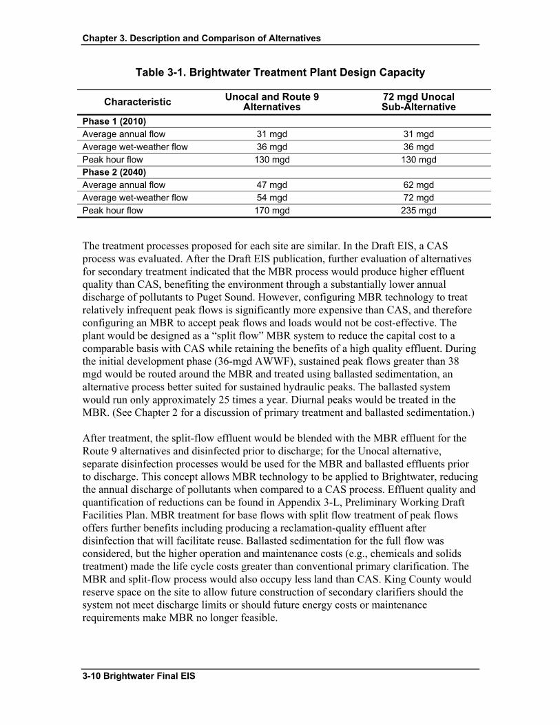
Both sites, Route 9 and Unocal, are based on the same design wastewater flow capacities: 36 mgd AWWF in 2010 and 54 mgd AWWF in 2040. However, in addition to these design capacities, the Unocal site has a sub-alternative that allows the future option of routing wastewater flow from the existing treatment plants in Edmonds and/or Lynnwood to the Brightwater Treatment Plant. The additional flow would result in greater capacity requirements (72 mgd) at the Unocal site. The design capacities for the Brightwater Treatment Plant at the two sites are shown in Table 3-1.
Brightwater Final EIS 3-9
Chapter 3. Description and Comparison of Alternatives
Table 3-1. Brightwater Treatment Plant Design Capacity
Characteristic Unocal and Route 9 Alternatives
72 mgd Unocal Sub-Alternative
Phase 1 (2010) Average annual flow 31 mgd 31 mgd Average wet-weather flow 36 mgd 36 mgd Peak hour flow 130 mgd 130 mgd Phase 2 (2040) Average annual flow 47 mgd 62 mgd Average wet-weather flow 54 mgd 72 mgd Peak hour flow 170 mgd 235 mgd
The treatment processes proposed for each site are similar. In the Draft EIS, a CAS process was evaluated. After the Draft EIS publication, further evaluation of alternatives for secondary treatment indicated that the MBR process would produce higher effluent quality than CAS, benefiting the environment through a substantially lower annual discharge of pollutants to Puget Sound. However, configuring MBR technology to treat relatively infrequent peak flows is significantly more expensive than CAS, and therefore configuring an MBR to accept peak flows and loads would not be cost-effective. The plant would be designed as a “split flow” MBR system to reduce the capital cost to a comparable basis with CAS while retaining the benefits of a high quality effluent. During the initial development phase (36-mgd AWWF), sustained peak flows greater than 38 mgd would be routed around the MBR and treated using ballasted sedimentation, an alternative process better suited for sustained hydraulic peaks. The ballasted system would run only approximately 25 times a year. Diurnal peaks would be treated in the MBR. (See Chapter 2 for a discussion of primary treatment and ballasted sedimentation.)
After treatment, the split-flow effluent would be blended with the MBR effluent for the Route 9 alternatives and disinfected prior to discharge; for the Unocal alternative, separate disinfection processes would be used for the MBR and ballasted effluents prior to discharge. This concept allows MBR technology to be applied to Brightwater, reducing the annual discharge of pollutants when compared to a CAS process. Effluent quality and quantification of reductions can be found in Appendix 3-L, Preliminary Working Draft Facilities Plan. MBR treatment for base flows with split flow treatment of peak flows offers further benefits including producing a reclamation-quality effluent after disinfection that will facilitate reuse. Ballasted sedimentation for the full flow was considered, but the higher operation and maintenance costs (e.g., chemicals and solids treatment) made the life cycle costs greater than conventional primary clarification. The MBR and split-flow process would also occupy less land than CAS. King County would reserve space on the site to allow future construction of secondary clarifiers should the system not meet discharge limits or should future energy costs or maintenance requirements make MBR no longer feasible.
3-10 Brightwater Final EIS
Chapter 3. Description and Comparison of Alternatives
All flow would enter the plant though an influent pump station and receive preliminary treatment at the headworks through screening followed by aerated or vortex grit removal. Following preliminary treatment, the flow would enter a flow-split structure that would direct flows up to the split-stream threshold to conventional primary treatment and the MBR process; sustained flows in excess of the threshold for the MBRs will be directed to the ballasted sedimentation process. An average of about 25 split flow events are anticipated annually. All flow would be disinfected before being discharged to Puget Sound. The purpose of disinfection is to kill remaining pathogens in the plant effluent to a level that complies with the effluent discharge permit. Prior to discharge to Puget Sound, disinfected flows would be dechlorinated as needed to meet permit requirements.
Solids Processing and Biosolids Management
Solids handling consists of thickening the primary and secondary solids, followed by anaerobic digestion and dewatering. (See Chapter 2 for a more complete discussion of solids processing.) The MBR would produce about 10 percent less solids than CAS due to the longer solids retention time. During peak month conditions, the MBR would produce approximately 2.5 percent more solids than CAS due to production of ballasted sludge, which includes chemical sludge. The thickening process removes water from the solids prior to anaerobic digestion and reduces the volume of solids, thus reducing the downstream treatment and equipment requirements. Anaerobic digestion stabilizes the solids by converting the organic matter to methane gas and carbon dioxide. Dewatering mechanically removes water from the digested biosolids prior to hauling. Reducing the water content reduces the cost of transporting the biosolids cake, as well as the size and amount of equipment needed. An enclosed truck bay would be provided for loading the dewatered biosolids into hauling vehicles.
Space would be reserved onsite to allow staging of up to eight biosolids trucks, two in the enclosed loading bay and six in an outdoor staging area. The biosolids trucks would have provisions for odor control in the staging area. Flexible hose would be used to connect the trucks parked in the staging area to a carbon system. Foul air from the truck beds would be ventilated and treated by the carbon system prior to discharge to the atmosphere.
The stabilized, dewatered biosolids would be hauled offsite and beneficially used along with biosolids from the West Point and South Treatment Plants. King County manages biosolids through land application to agricultural and forestry lands and by processing biosolids into a compost product. It is anticipated that the majority of the biosolids will be managed by land application, with composting providing an alternative means of biosolids management during periods of extended inclement weather, or when there is a market demand for compost.
Brightwater Final EIS 3-11
Chapter 3. Description and Comparison of Alternatives
Water Reuse
For either of the potential Brightwater sites, 5 mgd of reclaimed water capacity would be provided at the treatment plant when it comes online in 2010. Space would be reserved onsite for possible future expansion to provide up to 54 mgd of reuse water in the long term as demand increases and other potential opportunities are identified. The water reuse program would provide flexibility to accommodate uses and demand as it occurs. (See Appendix 3-D, Reclaimed Water Technology Review and Evaluation of Potential Water Reuse Opportunities.) Capacity for water reuse can be added as the demand increases.
Effluent from the MBR would meet all but one of the water quality requirements for Class A reclaimed water. The only additional process required is disinfection at a higher dose than that required for secondary effluent, which would enable the system to comply with the more stringent total coliform limit for Class A reclaimed water. UV disinfection would be used for the reuse system at both sites. Some sodium hypochlorite may be added in the distribution system onsite to maintain disinfection within the pipelines. The reuse process tanks would be covered and the process air vented to the odor control system.
The reclaimed water would be used onsite for landscape irrigation, tank cleaning, and other processes that do not require potable water. Reclaimed water is being considered for firefighting and fire suppression. However, for this Final EIS, potable water was assumed for both firefighting and fire suppression. The water also may, at some future date, be distributed offsite using a reuse pump station, which would be located at the treatment plant and would pump the water to the distribution system. The reuse pump station would be built in Phase 1 with an initial capacity of 5 mgd for onsite use, and would be designed to facilitate expansion in the future as offsite demand for reclaimed water increases. King County has identified potential users within a 5-mile radius of both the Route 9 and Unocal sites and along the Route 9–195th Street effluent conveyance line. These users represent a potential demand for up to 10.1 mgd of reclaimed water for the Route 9 system and 7.4 mgd for the Unocal site. In addition, up to 10 mgd of agricultural demand in the Sammamish Valley could be served at some future date by Brightwater instead of developing a separate Sammamish Reuse Treatment Facility in the valley.
The analysis of potential reclaimed water demand involved the identification of non-potable water users, including irrigation and industrial water uses, within the study area. The sites were golf courses, parks (with extensive irrigation), commercial nurseries, cemeteries, and industrial parks. The industrial uses of reclaimed water include cooling and process water. The water use for these sites was estimated, and those sites that use more than 100,000 gallons per day were included as having the potential for reclaimed water demand. The potential demand for both systems includes a mix of golf courses, cemeteries, and commercial/industrial uses. Appendix 3-D, Reclaimed Water Technology Review and Evaluation of Potential Water Reuse Opportunities, describes the possible demand for reclaimed water in more detail.
3-12 Brightwater Final EIS
Chapter 3. Description and Comparison of Alternatives
Delivery of reclaimed water to potential and future users would be through a distribution system separate from, but connected to, the Brightwater conveyance system. King County could “tap into” the Brightwater effluent pipeline as required by future demand. Beyond the use of the effluent pipeline, development of the reclaimed water distribution system is not part of the Brightwater proposal. Any future decision by King County to distribute reclaimed water offsite will be preceded by appropriate environmental review.
3.2.1.2 Odor Control Common to All Action Alternatives
The odor control approach at Brightwater is much more stringent than typical wastewater treatment plants and represents current state-of-the-art design for odor control. All process units would be covered, including the influent wet well, screenings and grit handling, primary clarifiers, aeration basins and membrane tanks, and disinfection. Buildings such as headworks and solids handling (thickening and dewatering processes) would have the process air and equipment fully enclosed. To remove odors, the covered process units, enclosed buildings, and loading areas would be under negative pressure to capture all process air for treatment by the odor control systems. There would be five separate odor control systems:
• Influent pump station
• Headworks and primary treatment
• Secondary treatment and disinfection
• Solids handling building and biosolids truck staging
• Digester gas pressure relief emergency vents (carbon only)
Each odor control system would treat the process air using multistage chemical scrubbers followed by a final polishing stage of carbon adsorption. Each stage would treat the process air to a greater degree. The exhaust air from the carbon polishers would be discharged from stacks to the atmosphere. The concentrations of odorous air (measured as hydrogen sulfide, ammonia, and total odor) would be below the detection thresholds at and beyond the plant property line at both sites under peak odor conditions. In addition to the chemical scrubbers, carbon scrubbers would treat any digester gas that may be discharged through emergency pressure release vents. Chapter 5 and Appendix 5-A, Odor and Air Quality: Treatment Plant, include additional information on odor control criteria, technologies, and modeling results.
Brightwater Final EIS 3-13
Chapter 3. Description and Comparison of Alternatives
3.2.1.3 Other Onsite Facilities Common to All Action Alternatives
Influent Pump Station (IPS)
An IPS would be required to lift wastewater from the influent pipeline up into the preliminary treatment process (headworks). The IPS would be constructed as a wet well/dry well pump station with the pumps separated from the wet well by divider walls. The pump station would be a reinforced concrete structure with a sufficient number of pumps installed to pump the peak hourly flow with the largest unit out of service. The IPS would contain the following functional components: mechanical pumping equipment, electrical control and monitoring equipment, and odor control equipment.
Administration Building
The Administration Building is anticipated to be a two-story structure housing the administrative offices, laboratory, conference rooms, operations and process control center, restrooms, lockers, visitor reception area, lunchroom, archive and equipment storage areas, document production facilities, and a library. The operations and process control center would be the main location from which operations staff would monitor and control the treatment processes via the plant supervisory control and data acquisition (SCADA) system.
Maintenance Building
The Maintenance Building would provide a facility for performing repairs on equipment that cannot be performed in-place. It is anticipated to be a one- to two-story structure that houses a machine shop and repair facilities, spare parts storage, and maintenance staff offices. The building would have drive-in truck maintenance bays to facilitate loading and unloading of equipment.
Chemical Building
The Chemical Building would be used to store and distribute chemicals for odor control, ballasted sedimentation, and disinfection. Odor control chemicals would include sodium hypochlorite, sodium hydroxide, and potentially sulfuric acid. Ballasted sedimentation chemicals would include iron salts (ferric chloride) or alum. Sodium hypochlorite would be used for effluent disinfection and prechlorination of the influent. Polymer would be used for thickening and dewatering. Membrane cleaning chemicals would include sodium hydroxide, citric acid, sodium hypochlorite, and/or sodium bisulfide. Chemicals would be delivered by truck and stored in bulk storage tanks inside the building. Polymer may be
3-14 Brightwater Final EIS
Chapter 3. Description and Comparison of Alternatives
delivered in bulk liquid or dry form, diluted into solution onsite, and stored in the solids handling building. All chemical storage and handling would be designed to comply with the applicable local, state, and federal regulations, including the Uniform Fire Code (UFC), Resource Conservation and Recovery Act (RCRA), and Occupational Safety and Health Administration (OSHA). See Appendix 3-A, Project Description: Treatment Plant, for more detail on types and quantities of chemicals that will be used.
Cogeneration Facility
Two independent energy feeds are being provided to meet reliability requirements for all operating conditions, including peak flow. King County has decided to provide onsite generation for average conditions if the dual-feed electricity is not available and to help manage energy costs by providing alternatives to power from the electric grid should onsite generation be more cost-effective. In support of this policy, a cogeneration facility would be located at either of the treatment plant sites to provide capacity for the average annual consumption of 7 to 8 megawatts (MW) of electricity in Phase 1 (2010). Additional equipment would be added in Phase 2 (2040). This facility would be able to provide all power for the treatment plant under average operating conditions. The cogeneration facility would contain gas turbines, reciprocating engines, and/or fuel cells that would provide electrical power using biogas (gas produced during the treatment plant’s anaerobic digestion process) and natural gas as the fuel source. The facility would provide sufficient power to run the entire treatment facility at AWWF capacity, including the influent pump station using natural gas. Biogas would be used under normal operations to offset the power required from the electric grid.
One standby diesel generator of approximately 250-kilowatt (kW) output would be provided in Phase 1 for backup power in an emergency situation to serve essential life and safety needs, including critical lighting and ventilation, and to start the cogeneration system. Approximately 1,000 gallons of diesel fuel would be stored onsite to provide 48 hours of operation. The diesel fuel would be stored at the vehicle fueling station. For Phase 2 (2040), a second 250-kW generator would be added to provide a total of 500 kW generation capacity, with 2,000 gallons of diesel fuel storage.
3.2.1.4 Operation Characteristics Common to All Action Alternatives
Hours of Operation and Staffing
The Brightwater Treatment Plant would operate 24 hours per day, 7 days per week. During Phase 1, the facility would employ between 47 and 52 full-time employees to operate, maintain, and manage the plant and provide required administrative functions. Of these, between 33 and 39 would work the day shift; in addition, four crews of three employees each would work 12-hour shifts to provide round-the-clock coverage. During
Brightwater Final EIS 3-15

Chapter 3. Description and Comparison of Alternatives
Phase 2, the total plant employees would increase to between 67 and 75, with 41 to 49 of these on day shift and the remainder working 12-hour shifts. If the Unocal site were chosen and expansion to 72 mgd were to occur, the total number of employees would be between 90 and 100, with between 53 and 65 on the day shift.
In addition, between 3 and 7 full-time employees would be provided for the Community-Oriented Building.
Truck Trips During Operation
Operation of the Brightwater Treatment Plant would result in the need for trucks to deliver supplies and remove waste materials. Biosolids would also be trucked from the facilities to their reuse locations. The delivery of chemicals and the transport of biosolids would be the primary generator of truck trips. Information on the number of truck trips can be found in Technical Appendix 3-A Project Description: Treatment Plant.
Energy Usage
Energy requirements were estimated on the basis of current energy use at the West Point and South Treatment Plants. These estimates were refined using assumptions regarding conservation and efficiency measures that would be incorporated into the design to meet energy code requirements and comply with King County energy efficiency policies. (See Chapter 8, for a description of these policies.) The energy consumed during operation of the treatment plant would be for both process usage (treatment equipment) and non-process usage (e.g., building lighting, ventilation, heating). Energy for influent and effluent pumping was also included in the estimates, as well as energy use for the pump station located at Portal 11 in the Unocal alternative.
3.2.1.5 Conveyance System Common to All Action Alternatives
System Overview
The Brightwater conveyance system would include an influent pipeline and, for Route 9 systems only, an effluent pipeline primarily constructed in tunnels. The system would also include several types of permanent facilities constructed at the primary portal sites. Examples of permanent facilities that could be located at portals include hydraulic control structures, dechlorination, sampling stations, and odor control; many of these facilities would be located underground. A new pump station could be constructed at PSA 41 or the Route 9 site for the Route 9 systems and would be constructed at PSA 11 for the Unocal System.
3-16 Brightwater Final EIS

Chapter 3. Description and Comparison of Alternatives
The portal siting areas are designated as either primary or secondary. Primary portal siting areas, those that clearly would be required for construction, have been identified along each corridor at intervals of approximately 20,000 feet. Primary portals are construction areas that include shafts where workers access the tunnel, materials and equipment are stored, and soil is removed. Secondary portal sites are unlikely to be needed; however, although not expected, there is still a possibility that one or more may be required based on geotechnical analysis performed during final design. A decision regarding the use of secondary portals will not be made until final design is completed. If needed, secondary portals may be used for temporary ventilation or ground improvement. If needed for ventilation, the secondary portals may also be used to supply grout. If required, secondary portals would be located within approximately 10,000 feet of another primary or secondary portal. Both primary and secondary portal locations are identified in this Final EIS, but the focus of the impact evaluation is on primary portals. Should use of secondary portals be required, an appropriate environmental evaluation would be conducted at the time of the decision during final design.
The conveyance facilities would convey influent to the new treatment plant, convey effluent to an outfall in Puget Sound, control potential odor impacts to surrounding neighborhoods, or provide access to the completed pipelines and tunnels for inspection and maintenance. The Brightwater conveyance system would comprise a number of components:
• An influent pipeline for carrying untreated wastewater to the plant.
• An effluent pipeline for carrying treated effluent from the plant to an outfall in Puget Sound (for Route 9 systems only).
• An offsite pump station to lift the wastewater to higher elevations so that it can continue to flow by gravity (Unocal System only). The Route 9 influent pump station is described as part of the treatment plant; an option to locate the influent pump station at Portal 41 instead, is also discussed.
• Portals to support tunneling construction and for pipeline access after construction.
• An outfall pipeline in Puget Sound with a diffuser at the end to mix the treated effluent with waters of Puget Sound.
The conveyance system would be designed to convey peak flows that would occur when the Brightwater Service Area has reached full development. The Brightwater System would be sized to accommodate peak flows up to 170 mgd (235 mgd for the Unocal 72-mgd sub-alternative, which includes flow from Edmonds and Lynnwood). This is the estimated peak flow generated in the Brightwater Service Area during a once per 20-year flow event in 2050.
The location and type of influent and effluent pipelines required for the conveyance system would depend on the site selected for the treatment plant. If the Route 9 site is selected, both an influent and an effluent pipeline would be required: one to carry untreated wastewater from King County’s existing sewer pipelines to the Route 9 site,
Brightwater Final EIS 3-17
Chapter 3. Description and Comparison of Alternatives
and one to carry treated effluent from the Route 9 site to the outfall. Connections to the existing sewer system in Kenmore and Bothell would occur at points in the system where flows from north and northeast King County and south Snohomish County converge. If the Unocal site is selected, an influent pipeline would be required to carry untreated wastewater from the existing pipelines to the Unocal site, and the effluent would be discharged to an outfall pipeline that would begin adjacent to the Unocal site.
Pipelines and Tunnels
Most of the conveyance pipelines with diameters greater than 8 feet would be constructed by tunneling methods using tunnel boring machines (TBMs). Other construction methods such as microtunneling, open cut, or bore-and-jack construction may be used for constructing pipelines that connect new tunnels and pump stations to existing facilities. These connecting pipelines would range in length from approximately 100 to 4,000 feet.
The conveyance system would be comprised of gravity pipelines, pressure pipelines, and force mains. In gravity pipeline sections, the influent or effluent flows by gravity, and the pipe is not necessarily flowing full. In pressure pipeline and force main sections, the pipe is full, and the influent or effluent flows by pressure. The pressure in a pressure pipeline results from a source of flow at a higher elevation; in force mains, the pressure is generated by a pump station. Gravity pipeline sections would range between approximately 2 and 12.5 feet in diameter. Pressure pipelines and force mains would range from 3 to 10 feet in diameter. Where tunneling construction is used, the pipelines would be placed within the tunnels or the inside of the tunnel structure would serve as the conveyance pipe. When the influent and effluent pipelines follow the same corridor, both the influent and effluent pipelines would be placed within a single, larger-diameter tunnel. The spaces in the tunnel between the pipelines would be filled with cement grout.
The tunnels would range in depth from 40 feet to more than 450 feet below the ground surface, depending on the topography above the tunnel and the pipe gradient needed to maintain flow. Tunnel outer diameters would range from 14 to 24 feet, depending on the size and number of pipelines contained within the tunnel. Microtunnels would range between 3 and 8 feet in diameter. Specific information regarding the tunnel and pipeline diameters for each of the conveyance system alternatives is contained below in the discussion of conveyance systems for each alternative. Additional detail is included in Appendix 3-B, Project Description: Conveyance.
Each conveyance tunnel pipeline has been identified in the Final EIS as a 1,000-foot-wide corridor which represents the general alignment that conveyance tunnels and pipelines could follow. The tunnels themselves would be 14 to 24 feet wide and are mostly situated in public right-of-way under streets. These corridors are much wider than the actual utility easement that would be acquired in private property, estimated to be between 22 and 52 feet wide depending on tunnel diameter and location. Initially identifying a wider corridor allows for the flexibility to accommodate site-specific conditions when finalizing a specific tunnel alignment within a corridor during detailed design.
3-18 Brightwater Final EIS

Chapter 3. Description and Comparison of Alternatives
Primary Portals
Portals are major components of the conveyance system that provide access from the ground surface for launching and retrieving TBM equipment, removing soils, and installing pipes during construction. Portals also provide long-term access to the tunnels. Portal siting areas are 72 acres in size, within which a minimum area of 1 to 2 acres would ultimately be selected for construction of primary portals.
Multiple candidate sites were identified within each PSA. (The locations of these sites are discussed in more detail in the description of specific alternatives below.) These candidate sites were identified based on site visits and available information. Sensitive areas such as wetlands or high-quality upland habitat or forested areas were avoided wherever possible. Priority was given to sites that were publicly owned, and to publicly or privately owned undeveloped or underdeveloped sites. Developed property was evaluated if there were no undeveloped or underdeveloped sites within the portal siting area. Among the developed properties, publicly owned sites, commercial/industrial, and residential sites were considered. The primary portal minimum site size of 1 to 2 acres was established to provide adequate area for equipment access, staging, and operation during construction. In the event that a larger parcel of land is available and selected for the portal site, the entire site may be acquired. The remaining area may be used for construction staging, such as materials and equipment storage. After construction is complete, only the area needed to support the permanent facilities would be developed, and the rest of the site could be made available for other compatible uses in conjunction with the local jurisdiction and community or returned to the use of the original landowner if that were desired.
Each primary portal would be designated as a launching or a recovery portal. The portal where the TBM operation starts is termed a “launching” portal. This is because the TBM would be assembled and started (launched) from this portal, and the tunnel excavation, lining, and ventilation operations would follow the TBM (i.e., most of the work would occur at these portals). Another portal would be required at the end of each segment. Once the tunnel segment is completed, the TBM would be removed from the tunnel through these portals, called “recovery ”portals. The recovery portal also would provide ventilation and egress and access during the final lining, cleanup, and testing stage of the project. Figures 3-1 and 3-2 show typical layouts of launching and recovery portals during construction.
Secondary Portals
Candidate portal sites were identified for all potential portal siting areas during the portal screening process. At the same time, progress on conveyance design allowed portals to be eliminated as launching or recovery portals, and these were redesignated as “secondary portals.” These secondary portals are not anticipated to be needed, but if they were, the use will be much less intense than envisioned early in design and portal screening. Substantially less land would be needed than for the primary portals, on the order of one-
Brightwater Final EIS 3-19
Chapter 3. Description and Comparison of Alternatives
half acre or less. For the purposes of the EIS evaluation, however, a worst-case scenario of 1 to 2 acres was used for the impact analysis.
If it is determined that secondary portals are required, King County will perform additional screening. Secondary portals would be smaller in size than primary portals and the smaller site area needed will allow King County more flexibility in placement to avoid impacts to residences and sensitive environmental resources, such as wetlands and streams.
If needed, secondary portals may be used for temporary ventilation and/or ground improvement. If used for ventilation, the secondary portals may also be used for supplying grout to the tunnel. For each of these uses, the diameter of the secondary portal would be up to 8 feet, as compared with up to 50 feet for primary portals. Overall construction duration (including mobilization and demobilization) for secondary portal sites would range between 1 and 2 months, with a maximum of approximately 6 months.
Permanent Facilities
Several types of permanent facilities would be constructed at the primary portal sites. These facilities would manage the flow and hydraulics throughout the conveyance system. Facilities would include below-grade hydraulic control structures such as diversion structures, drop structures, force main discharge structures, and transition structures as well as above-grade facilities such as pump stations, dechlorination, chemical injection, and odor control facilities. The permanent facilities associated with each conveyance system alternative are discussed in the sections on individual alternatives later in this chapter.
3.2.1.6 Connections to Existing Systems Common to All Action Alternatives
Several connections would be made to the existing sewer system to direct flows to the Route 9 or Unocal sites. Connections would be made to the following facilities:
• Kenmore Pump Station at Portal 11
• Kenmore local sewer system at Portal 11
• Swamp Creek trunk sewer at Portal 44 (Route 9 alternatives only)
• North Creek Pump Station at Portal 41 (Route 9 alternatives) or Portal 14 (Unocal alternative)
Kenmore Pump Station Connection
The existing Kenmore-Bothell Interceptor conveys flows to the existing Kenmore Pump Station, located near Portal 11. The Kenmore-Bothell Interceptor connects to the
3-20 Brightwater Final EIS

Chapter 3. Description and Comparison of Alternatives
Kenmore Pump Station’s influent structure. A new diversion structure would replace the existing Kenmore Pump Station influent structure. A 72-inch-diameter pipeline would convey flow to Portal 11 from the proposed diversion structure and connect to the influent tunnel via a junction structure that would be located within Portal 11. The 72-inch pipeline connecting the diversion and junction structures would be approximately 100 to 1,500 feet long, depending on the location of the Portal 11 site. The 72-inch-diameter pipeline would be constructed using either open-cut or microtunneling methods. The existing Kenmore Pump Station would be used for flow diversions to the West Point Wastewater Treatment Plant (WWTP) when needed for flow flexibility and routing.
Kenmore Local Sewer System Connection
Connections would be made to the existing local sewer system in the Kenmore area when needed, based on flow management demands. These connections would be located in the vicinity of NE 175th Street and 61st Avenue NE. The flow would be directed from there to PSA 11. A 21-inch-diameter pipeline would be constructed along NE 175th Street between 61st Avenue NE and a new diversion structure at the Kenmore Pump Station. The diversion structure would discharge to the drop structure located in Portal 11. The drop structure would connect to the influent tunnel. The 21-inch-diameter pipeline would be constructed using either open-cut or microtunneling methods.
Swamp Creek Trunk Connection
The Swamp Creek Trunk currently flows into the Bothell-Woodinville Interceptor and then to the Kenmore Pump Station. The Swamp Creek Trunk alignment is close to the proposed location for Portal 44; therefore, Swamp Creek flows from north of NE 195th Street may be diverted directly to Portal 44 for both the Route 9–195th Street and 228th Street alternatives. Swamp Creek continues to flow south of NE 195th Street would flow into the Bothell-Woodinville Interceptor and to the Kenmore Pump Station. A new manhole would be constructed on the existing Swamp Creek Trunk in the vicinity of NE 195th Street and 73rd Avenue NE. A new 36-inch-diameter pipeline would be constructed along NE 195th Street between 73rd Avenue NE and Portal 44. The pipeline would discharge into the drop structure located in Portal 44. The drop structure would connect to the influent tunnel. The 36-inch-diameter pipeline would be constructed using either open-cut or microtunneling methods.
North Creek Pump Station Connection
The existing North Creek Pump Station receives flows from the Bothell-Woodinville Interceptor and the North Creek Trunk via the existing North Creek diversion structure. Flows can be conveyed to the North Creek Pump Station or, during periods of wet weather, to the North Creek Storage Facility or the Kenmore Pump Station via the
Brightwater Final EIS 3-21
Chapter 3. Description and Comparison of Alternatives
Kenmore-Bothell Interceptor. This entire system would connect directly to the new influent tunnel via a diversion structure.
The diversion structure could be either a new structure or the existing North Creek diversion structure could be modified to accommodate the new conveyance system. A new 72-inch-diameter pipeline would convey flows from the diversion structure to a drop structure located within Portal 14 (Unocal system) or Portal 41 (Route 9 system). The drop structure would connect to the proposed influent tunnel.
The 72-inch-diameter pipeline would be approximately 100 to 4,000 feet in length depending on the location of Portal 14 or Portal 41. The connection would be constructed by microtunneling with some open-cut construction on the portal site and at the North Creek Pump Station. The existing North Creek Pump Station would remain and would be used for flow routing flexibility to send flows to the South Plant. The North Creek Storage Facility would be used for storage of peak flows when needed.
3.2.1.7 Outfall Common to All Action Alternatives
For any of the Brightwater System alternatives, an outfall would be constructed to discharge the treated effluent into Puget Sound. The outfall would consist of a pipeline starting on land and continuing under water. A diffuser at the end of the pipeline would disperse the effluent into Puget Sound through ports placed along its length. The diffuser would be designed to discharge the full range of Brightwater flows.
For the onshore and nearshore sections of the outfall, the pipeline is proposed to be constructed in trenches (open-cut construction). Open-cut construction is preferred for the installation of onshore and nearshore outfall segments as opposed to microtunneled construction because impassable barriers, such as piles, logs, and boulders, have created difficulties for a significant number of similar microtunneling projects in the Puget Sound region. If microtunneling were the construction method, such barriers, if encountered, could necessitate abandoning the tunnel alignment or require the excavation of an unanticipated shaft in the near shore to provide access to the tunneling face and remove the barrier. This could potentially create significant adverse environmental impacts and would substantially increase construction costs. Outfall alignment and construction methods are described in Appendix 3-C, Project Description: Outfall, and Appendix 3-F, Nearshore Alignment and Construction Methods Alternatives.
Preferred outfall alignments within two 3,000-foot-wide outfall siting areas (called zones) are being evaluated in this EIS. The alignments are representative of feasible final design outfalls and were developed as a basis for estimating pipeline length, potential slope conditions, and other parameters. The exact outfall alignment would be determined after a more thorough evaluation of site-specific conditions during final project design.
3-22 Brightwater Final EIS
Chapter 3. Description and Comparison of Alternatives
3.2.1.8 Conveyance Safety Relief Point Common to All Action Alternatives
One of the goals of the Brightwater project is to add system conveyance and treatment capacity and flexibility to prevent wastewater overflows that would occur in the existing system north of Lake Washington and the Sammamish River if Brightwater were not built. With implementation of this project, such overflows would be eliminated except in rare and extreme conditions, thereby greatly reducing the potential for adverse impacts on water quality in adjacent surface waters. However, even with Brightwater, emergency wastewater overflows could potentially occur during unusual combinations of extremely high storm-influenced flows and multiple equipment and power failures.
Although it would be a very rare event resulting from extreme conditions, the potential overflow event must be planned for and designed into the system so that releases of untreated wastewater do not occur in places where people may come into contact with it, such as streets and homes. The Brightwater conveyance and treatment system would be designed to be extremely reliable, with standby power and redundant equipment to sustain conveyance and treatment plant operations during power outages and equipment failure. However, strategies to manage inflows to the Brightwater plant during periods of extreme rainfall are also needed so that conveyance and treatment capacities are not exceeded. To protect public health and environmental quality, King County has developed a five-part emergency flow management system for both the Unocal and Route 9 systems: (1) diverting flows to the West Point and South Treatment Plants, (2) diverting excess flows into the existing Logboom and North Creek Storage Facilities, (3) storing flows in new and existing conveyance pipelines, (4) using emergency generators to keep new and existing pumping stations operational in the event of power outages, and (5) diverting partially treated wastewater through the effluent system and outfall to Puget Sound.
If all measures outlined above had been implemented and there was still a threat of uncontrolled overflows, wastewater would be discharged from a safety relief point into the lower Sammamish River just above the point where the river flows into Lake Washington in the Kenmore area. Discharge from the safety relief point would be extremely rare and would occur only as the result of catastrophic events as opposed to those expected during normal year-round operations. The control structure would be a two-chamber concrete vault, approximately 28 feet by 32 feet. If the capacity of the influent tunnel and existing storage facilities is exceeded, stormwater-diluted wastewater would enter the first of the two chambers. As the chambers reached capacity, flows would discharge to the Sammamish River through two 72-inch pipes for the duration of the event. The emergency relief structure and connecting pipes would be cleaned after the event. No additional safety relief structure would be provided on the Route 9 site because flows that reach the plant can flow by gravity through the plant to Puget Sound by way of the effluent pipeline even if the power has failed. However, additional safety relief would be required for the Unocal site where the remote possibility exists for the plant to fail while
Brightwater Final EIS 3-23

Chapter 3. Description and Comparison of Alternatives
the conveyance system pump station at Kenmore is still delivering flow. To protect against this event, a safety relief system would be designed at the Unocal site to discharge influent wastewater to Puget Sound via a plant bypass from the onsite influent pump station wet well to the plant’s effluent outfall. The bypass from the wet well would be equipped with a gate that would open automatically should the influent pumps or effluent pumps fail.
3.2.1.9 Construction Activities and Schedule Common to All Action Alternatives
This section briefly discusses construction activities and the construction schedule for the Brightwater System. More detailed discussion of construction activities, methods, and schedules can be found in Appendix 3-G, Construction Approach and Schedule.
Construction Activities
In general, construction activities can be divided into several phases. The first stage—bidding and equipment procurement—does not have impacts on the environment, but can require a lengthy period of time; the acquisition of a tunnel boring machine, for example, takes approximately 1 year. The second stage, site preparation, involves the demolition of any existing structures that will not be reused (for example, at the treatment plant or portal sites), as well as any grading that needs to occur. Following site preparation, active construction begins. For the treatment plant, this would include development of all the major facilities—such as pump station(s), headworks, clarifiers, aeration basins, digesters, —and the installation of equipment such as odor control and electronic instrumentation and control systems. For conveyance, this phase includes construction of the portals, excavation and lining of the tunnels, and development of associated permanent facilities such as drop structures. Construction of the outfall and diffuser would include open-cut through the nearshore area and placement of the pipe in the trench and along the sea floor. For all system components, active construction would be followed by a period of site cleanup and landscaping or restoration. All components would be tested using clean water prior to being put into service.
A variety of construction methods would be used for the Brightwater system, depending on the final design details and on the contractor selected to perform the work.
Construction Schedule
The overall construction schedule for the Brightwater System would span approximately 5-3/4 years (70 months), from early 2005 to the end of 2010. This time period would begin with demolition and site preparation and end with treatment plant testing and commissioning. Major construction activities involving earth movement and truck traffic would be essentially complete by early 2010. Construction of the conveyance system and
3-24 Brightwater Final EIS

Chapter 3. Description and Comparison of Alternatives
outfall would take up to approximately 5 years, depending upon the alternative selected. Construction at each individual primary portal location, beginning with portal development and including excavation, lining, and portal cleanup, would take between 22 and 39 months; the average duration for portal construction activity would be approximately 29 months. Construction duration at secondary portals, if needed, would be less than for primary portals (6 months or less) and be dependent on the activities required. Many facilities would be constructed concurrently. More detailed schedule information by portal location is provided in the sections of this chapter specific to each alternative.
3.2.2 Route 9–195th Street System The Route 9–195th Street System, the Preferred Alternative, would consist of a treatment plant built at the Route 9 site in unincorporated Snohomish County north of the City of Woodinville, and a conveyance corridor that includes both (1) an influent pipeline extending from existing pipelines in Kenmore and Bothell to the treatment plant site, and (2) an effluent pipeline from the treatment plant site to an outfall in Puget Sound. This proposed conveyance system generally would follow NE 195th Street and NE 205th Street. (See the System Alternatives map in the back cover of this volume for details of the 195th Street System.)
3.2.2.1 Treatment Plant: Route 9–195th Street System
As described earlier, the proposed Brightwater Treatment Plant would be designed to treat an average of 36 mgd of wastewater by 2010 with features to allow for a future expansion to 54 mgd in 2040. The Brightwater plant would provide secondary treatment of wastewater to produce an effluent that meets state Water Quality Standards for discharge to Puget Sound.
Site Location and Layout
Site Location and Characteristics The Route 9 site lies inland, approximately 12.5 miles east of Puget Sound. It is located in unincorporated Snohomish County east of State Route (SR) 9, just north of the City of Woodinville and northeast of the intersection of SR-9 and SR-522 (Figure 3-3). The site consists of parcels owned by various individuals, businesses, and organizations. Low-density, single-family residences occupy the majority of the area surrounding the site, except to the southwest where light industrial businesses are located.
The 114.3-acre site is roughly rectangular in shape. The northern portion of the site (37.3 acres), which is outside the Urban Growth Area (UGA), is largely undeveloped and partially forested, with wetlands present. This area would not be used for construction of treatment facilities. Instead compensatory wetland mitigation would be provided in this
Brightwater Final EIS 3-25
Chapter 3. Description and Comparison of Alternatives
area outside the UGA. The central and southern portions of the site have been developed for commercial and industrial land uses and would be used for treatment of wastewater and stormwater.
The Route 9 site slopes moderately (less than 10 percent) to the southwest. The elevation of the area planned for treatment facilities ranges from a low of 150 feet above sea level on the west side to a high of 225 feet along part of the east property line. Portions of the site along the eastern edge and outside the area planned for treatment plant facilities slope at 10 to 30 percent. Little Bear Creek is located west of the proposed treatment plant site and west of SR-9. Several small watercourses flow across the site from east to west in underground pipes and open ditches. In addition, three streams traverse the site before discharging into Little Bear Creek. One in the north, called Unnamed Creek, originates northeast of the Route 9 site and traverses the northern part of the site outside of the UGA in a southwest direction. The second, called Howell Creek, is located in the southern portion of the site. The third stream, 228th Street Creek, has two channels: a narrow, straight, ditch-like channel that separates the developed southern portion of the site from the undeveloped northern portion, and a channel that is mostly piped under the site, daylighting briefly along the railroad tracks at the eastern site boundary.
Soil and groundwater on the site may be contaminated as the result of past and current industrial uses. One property on the site is on the Washington State Department of Ecology's (Ecology) Model Toxics Control Act (MTCA) Confirmed and Suspected Contaminated Sites List, as of May 2001. It has been ranked as a 5, the lowest level of risk, and it is awaiting remedial action. For purposes of this EIS, it is assumed that some soil and groundwater contamination would be encountered during the large-scale excavation required for construction of the Brightwater plant. Additional investigations would be conducted to confirm the type and extent of contamination present and method of remediation.
A portion of the Route 9 site is situated over the southern boundary of the Cross Valley Sole Source Aquifer (CVSSA) but is positioned entirely outside the Cross Valley Water District’s wellhead protection area and is in the “discharge zone” of the CVSSA. This means that water under the Route 9 site is moving out of the aquifer as opposed to into the aquifer. Chapter 6 of this EIS includes additional information on the aquifer, groundwater flow, and potential impacts of treatment plant construction and operation.
Site Preparation Preparation of the Route 9 site for construction would involve demolition of existing structures; excavation and grading; installation of retaining walls, access roadways, underground utilities, and drainage systems; and relocation of some onsite streams and watercourses. Approximately 800,000 cubic yards of soil excavation would be required for general grading and excavation for the foundations of specific structures. Of this total, over 500,000 cubic yards are expected to be reused onsite for backfill in low areas and to construct berms and other landscape features. It is anticipated that about 345,000 cubic yards of excavated soils would be hauled offsite. Since the Route 9 site is relatively flat,
3-26 Brightwater Final EIS

Chapter 3. Description and Comparison of Alternatives
it would require few retaining walls; about 27,000 square feet of such walls are anticipated.
Relocation of streams would be an important element of site preparation. The several unnamed watercourses that run from east to west across the site would be collected across the eastern site boundary and routed to the north and south ends of the site. A salmon rearing pond in the Woodinville North Business Park would be relocated to the northern portion of the site and upgraded.
Facility Layout A preliminary site plan for the Brightwater Treatment Plant has been prepared for the Route 9 site to show the location and arrangement of major treatment and support facilities (Figure 3-4). The total footprint of the treatment plant and support facilities would be approximately 43 acres, with an additional 4 acres reserved for expansion to full-flow conventional activated sludge in the future, if necessary, and Class A biosolids production. The treatment plant and stormwater management facilities would occupy 80.6 acres. Primary vehicle access to the site would be from SR-9 and 228th Street SE, where a traffic light currently exists. Secondary access would be provided near the south end of the property.
The wastewater treatment facilities would be located in the central and southern area of the site. The Administration and Maintenance Buildings would be located in the southern part of the treatment facility close to the influent and solids handling system, which generally requires the most operation and maintenance. The liquid treatment facilities would be on the eastern side of the site, arranged from south to north based on process flow sequence. Water reuse facilities would be located at the northern end of the plant. The solids treatment and handling units would be located in the southern portion of the treatment plant near preliminary and primary treatment. Odor control facilities would be decentralized and located near their respective process units: influent pump station, preliminary and primary treatment, secondary treatment, solids handling and biosolids truck staging, and digester gas pressure relief emergency vents (carbon only). Locations of the facilities are shown in Figure 3-4, and more detail is provided in Appendix 3-A, Project Description: Treatment Plant.
Treatment facilities would be constructed primarily of reinforced concrete. Most of the process tanks would be below the ground surface and all tanks would be covered for odor control. Most of the mechanical and electrical equipment would be enclosed. Buildings, such as the administration building, could be constructed of brick, precast concrete or other materials that complement the surrounding area. Walkways would be paved with concrete; roadways would be paved with concrete, asphalt, or porous pavement depending on the intended use. The entire treatment system would be tested using clean water to ensure that all systems operate as designed before wastewater is introduced into the plant.
Stormwater generated at the treatment plant site would be managed at the site. Emphasis has been placed upon minimizing the amount of stormwater generated. The basic site
Brightwater Final EIS 3-27

Chapter 3. Description and Comparison of Alternatives
concept would meet this objective by restoring a large portion of the site to forested conditions. This measure would mimic the natural hydrologic processes of much of the site in its pre-developed, forested state. This forested area may also be used to disperse some of the stormwater generated by adjacent, built areas of the treatment plant. The project would take into account the guidelines contained in Ecology’s (2001) Stormwater Management Manual for Western Washington.
The final design will incorporate low impact development (LID) where feasible and cost-effective to minimize the amount of stormwater runoff. The LID measures that may be applied to this project include open site design, establishment of forested areas, vegetated roofs, porous pavement, bio-retention swales, and amended soil. Porous pavement may be used for automobile parking areas, light-use roadways, and sidewalks to promote stormwater infiltration. Vegetated roofs may be used on some of the process and non-process buildings. Such roofs are effective in temporarily storing and/or reducing runoff. Amended soils would be incorporated into the landscaped areas of the site. The stormwater infiltration and holding capacity of amended soils is greatly enhanced compared to the existing non-amended soils, also reducing runoff.
A canal is a central feature of the design concept that also would serve an important stormwater management function. The canal would be oriented north to south along the length of the site south of the UGA. It would be 60 feet wide and approximately 2,800 feet long. The canal would receive and detain clean runoff from roofs, low-maintenance landscaped areas, and other non-polluting areas of the project site. In addition, the canal may receive stormwater runoff that has been treated at other locations on the project site. Underground pipes or vaults may be used to provide detention within or immediately adjacent to the built areas of the treatment plant. A series of ponds, wetlands, and bio-swales would be constructed along the western side of the site. Stormwater from the treatment plant roads, parking areas, and other surfaces would be conveyed to this area for treatment and detention. The stormwater would then be routed to existing culverts under SR-9 and flow to Little Bear Creek. Storm runoff from areas of the plant that could be contaminated by wastewater, its byproducts, or chemicals would be collected and routed to the plant headworks for treatment.
A Community-Oriented Building could be provided as a mitigation measure to enhance public awareness and understanding of environmental issues, convey information about the natural water and wastewater cycles through education programs for school groups, and provide meeting and event space for community members.
Portal 41 Influent Pump Station Option This option includes eliminating the influent pump station from the Route 9 Treatment Plant site and relocating it to portal siting area 41. If this option were chosen to reduce potential environmental impacts, it would result in eliminating approximately 10,000 square feet of building footprint from the southern portion of the treatment plant site. This land area would be available as natural and/or landscaped open space.
3-28 Brightwater Final EIS
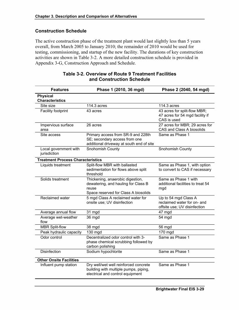
Chapter 3. Description and Comparison of Alternatives
Construction Schedule
The active construction phase of the treatment plant would last slightly less than 5 years overall, from March 2005 to January 2010; the remainder of 2010 would be used for testing, commissioning, and startup of the new facility. The durations of key construction activities are shown in Table 3-2. A more detailed construction schedule is provided in Appendix 3-G, Construction Approach and Schedule.
Table 3-2. Overview of Route 9 Treatment Facilities and Construction Schedule
Features Phase 1 (2010, 36 mgd) Phase 2 (2040, 54 mgd) Physical Characteristics
Site size 114.3 acres 114.3 acres Facility footprint 43 acres 43 acres for split-flow MBR;
47 acres for 54 mgd facility if CAS is used
Impervious surface area
26 acres 27 acres for MBR; 29 acres for CAS and Class A biosolids
Site access Primary access from SR-9 and 228th SE; secondary access from one additional driveway at south end of site
Same as Phase 1
Local government with jurisdiction
Snohomish County Snohomish County
Treatment Process Characteristics Liquids treatment Split-flow MBR with ballasted
sedimentation for flows above split threshold
Same as Phase 1, with option to convert to CAS if necessary
Solids treatment Thickening, anaerobic digestion, dewatering, and hauling for Class B reuse Space reserved for Class A biosolids
Same as Phase 1 with additional facilities to treat 54 mgd
Reclaimed water 5 mgd Class A reclaimed water for onsite use; UV disinfection
Up to 54 mgd Class A reclaimed water for on- and offsite use; UV disinfection
Average annual flow 31 mgd 47 mgd Average wet-weather flow
36 mgd 54 mgd
MBR Split-flow 38 mgd 56 mgd Peak hydraulic capacity 130 mgd 170 mgd Odor control Decentralized odor control with 3-
phase chemical scrubbing followed by carbon polishing
Same as Phase 1
Disinfection Sodium hypochlorite Same as Phase 1
Other Onsite Facilities Influent pump station Dry well/wet well reinforced concrete
building with multiple pumps, piping, electrical and control equipment
Same as Phase 1
Brightwater Final EIS 3-29

Chapter 3. Description and Comparison of Alternatives
Table 3-2. Overview of Route 9 Treatment Facilities and Construction Schedule (cont.)
Features Phase 1 (2010, 36 mgd) Phase 2 (2040, 54 mgd) Other Onsite Facilities (cont.)
Reuse distribution pump station
Sized for 5 mgd onsite use; potential to increase according to demand
Up to 54 mgd for on and offsite use depending on demand
Non-process structures Administration building, maintenance facility, chemical storage building, cogeneration building, potential community-oriented building
Same as Phase 1
Parking 180 total spaces (including 100 for community-oriented building)
Same as Phase 1
Stormwater management
Swales, constructed wetlands, and ponds, including a central canal; discharge to Little Bear Creek
Same as Phase 1
Cogeneration Biogas and natural gas to generate sufficient power to run facility at AWWF; 7 MW
Same as Phase 1; 13 MW
Operational Features Number of employees 47 to 52, plus 3 to 7 at potential
community-oriented building 67 to 75, plus 3 to 7 at potential community-oriented building
Work hours by shift 33 to 39 day shift employees for WWTP, 3 to 7 day shift employees for potential community-oriented building, 12 employees on 12-hour shifts (4 crews)
41 to 49 day shift employees for WWTP, 3 to 7 day shift employees for potential community-oriented building, 24 to 26 employees on 12-hour shifts (4 crews)
Truck trips per week (solids removal and chemical deliveries)
52 one-way trips 76 one-way trips
Average energy demand energy use (including influent pumping)
7.7 MW 13.2 MW
Biosolids production 76.4 cubic yards/day at AWWF 114.6 cubic yards/day at AWWF
Construction Durationa Site preparation (includes demolition, mobilization, and structural excavation)
20 months (early 2005 to late 2006) To be developed at a later date
Facilities construction 54 months (late 2005 to mid-2010) To be developed at a later date
Plant startup and commissioning
16 months (late 2009 to late 2010) To be developed at a later date
Total Construction 70 months (early 2005 to late 2010) To be developed at a later date
aTotal construction duration is not the sum of the individual activities because some construction activities take place at the same time.
3-30 Brightwater Final EIS

Chapter 3. Description and Comparison of Alternatives
3.2.2.2 Conveyance System: Route 9–195th Street System
The Route 9–195th Street conveyance system would consist of an influent pipeline to a treatment plant built at the Route 9 site and an effluent pipeline to an outfall in Zone 7S off Point Wells. The influent pipeline, effluent pipeline, and portals for constructing the tunnels are shown in Figure 3-5. This proposed conveyance system is the Preferred Alternative and would generally follow NE 195th Street and NE 205th Street. The majority of the Route 9–195th Street conveyance system would be located in King County. An influent pump station would be located at the Route 9 plant site, and, because the conveyance system would be a combination of pressure pipelines and a gravity system, no other influent or effluent pump stations would be required within the conveyance system.
Potentially affected jurisdictions for the Route 9–195th Street conveyance system alternative would include the cities of Woodinville, Bothell, Kenmore, Lake Forest Park, and Shoreline; the Town of Woodway; and unincorporated King and Snohomish Counties.
Because the influent and effluent tunnel corridors would be next to each other between Portal 44 and the Route 9 site, the influent and effluent pipelines can be combined in a single, larger-diameter tunnel rather than two separate tunnels. The total conveyance alignment length, including influent and effluent tunnels, the combined tunnel section (which includes both influent and effluent pipelines), and the local connection pipelines, is approximately 15.9 miles.
As described previously, investigations are underway to determine if relocating the planned influent pump station from the Route 9 site to Portal 41 would provide greater environmental and operational benefits. For a more detailed description of this relocation option, see the discussion later in this section. The environmental analysis of this option can be found in relevant sections of each chapter of this EIS.
Table 3-3 provides an overview of the Route 9–195th Street conveyance system.
Influent Pipeline
The influent conveyance system would consist of primarily large-diameter pipelines constructed by tunneling. A relatively short pipeline connecting to the existing wastewater system between the North Creek Pump Station and Portal 41 would be constructed by microtunneling methods. Open-cut construction and/or microtunneling would also be used to connect the existing wastewater system to the new influent tunnel at Portal 11 and Portal 44. The route of the influent conveyance alignment generally follows 68th Avenue NE to NE 195th Street, then turns east on NE 195th Street to Portal 44. The alignment then runs east along NE 195th Street through the North Creek Business Park (Portal 41) to SR-522, and then north along SR-522 to the Route 9 site. Table 3-3 provides more detail on characteristics of the influent pipeline.
Brightwater Final EIS 3-31

Chapter 3. Description and Comparison of Alternatives
The Route 9–195th Street conveyance system would combine the influent and effluent pipelines in one larger-diameter tunnel along NE 195th Street and SR-522, between Portal 44 and the Route 9 site. Figure 3-6 shows a cross-section of the tunnel and Figure 3-7 shows a profile view. The total length of the influent tunnel alignment is 8.1 miles, including 1.8 miles of local influent connection pipelines and 4.8 miles of combined tunnel section (which includes both influent and effluent pipelines). The actual length of the local connections depends on the final location of the portal sites.
Several local connections would be made to the existing sewer system to direct flows to the Route 9 site via the Route 9–195th Street conveyance system. Local connections are generally less than 1/2 mile long and would be between 21 and 72 inches in diameter. The preferred construction methods for these local connections are open-cut and/or microtunnel. Connections would be made to the following existing facilities:
• Kenmore Pump Station (Portal 11)
• Kenmore Local Sewer System (Portal 11), when necessary for flow management
• Swamp Creek Trunk Sewer (Portal 44)
• North Creek Pump Station (Portal 41)
Effluent Pipeline
The effluent conveyance pipeline for the Route 9–195th Street system would be placed in the same tunnel with the influent pipeline from the Route 9 site south along SR-522 and west along NE 195th Street to Portal 41, near the intersection of NE 195th Street and 120th Avenue NE. The combined tunnel would continue to follow NE 195th Street to Portal 44 at 80th Avenue NE. At this point, the effluent conveyance would diverge from the influent conveyance and would continue west along NE 195th Street in public and private rights-of-way until reaching Ballinger Way NE (SR-104). The corridor then would turn northwest along Ballinger Way NE, intersecting with Portal 5 at NE 205th Street (King County designation) /244th Street SW (Snohomish County designation) at the King/Snohomish County boundary. From this location, the corridor would run west along NE 205th Street until reaching Puget Sound at Point Wells (Portal 19), where it would connect to the Zone 7S outfall. The total length of the effluent tunnel alignment is approximately 7.8 miles, plus 4.8 miles of combined tunnel section (which includes both influent and effluent pipelines).
The 195th Street conveyance system would avoid the need for an effluent pumping station. The effluent pipeline would have a high point at Portal 5. See Figure 3-8 for a profile showing the approximate effluent tunnel depth. The final tunnel depth would be determined during design, based on geotechnical and hydraulic considerations.
3-32 Brightwater Final EIS

Chapter 3. Description and Comparison of Alternatives
Table 3-3. Overview of Route 9–195th Street Conveyance System Primary Portals
Tunnel/Reach (between primary portals)
Portal Siting Area Vicinity
(locations are approximate)
Portal Depth (feet)
Candidate Portal Sites, Sizes, and Access Roads
(See Figures 3-22 through 3-42)
Tunnel Reach Length/
Diameter Purpose of Primary Portal Construction Duration (years)
INFLUENT CORRIDOR
Portal 11 to Portal 44 Portal 11: Vicinity of NE 175th Street and 68th Avenue NE
45 11-A (2.3 acres); 11-B (4.3 acres); 11-C (4.1 acres); access via 68th Ave NE/ Juanita Dr./NE 175th St., Bothell Way NE (SR 522)
1.5 miles; 14-foot diameter
TBM launch; spoils receiving; local connection to Woodinville-Bothell Interceptor, and Juanita Trunk
Total construction: 2 – 2.5
Portal 44 to Portal 41 Portal 44: Vicinity of NE 195th Street and 80th Avenue NE
80 44-C (3.6 acres); 44-D (8.8 acres); 44-E (2.3 acres); access via NE Bothell Way (SR 522), NE 195th Street, 80th Avenue NE
2.4 miles (combined
influent/ effluent); 24-foot diameter
TBM launch, TBM retrieval, spoils receiving, local connection to Swamp Creek Trunk
Total construction: 3.5 - 4
Portal 41 to Route 9 Influent Pump Station
Portal 41: Vicinity of NE 195th Street and 120th Avenue NE
90 41-A (6.7 acres); 41-C (16.1 acres); 41-D (4.6 acres); 41-X (5.1 acres) 41-W (3.3 acres); 41-J (3.7 acres); access via I-405, NE 195th Street, 120th Avenue NE, Beardslee Blvd., Ross Rd., North Creek Parkway
2.4 miles (combined
influent/ effluent); 24-foot diameter
TBM launch, spoils receiving; local connection to Woodinville-Bothell Interceptor, North Creek Sewer Interceptor
Total construction: 3
IPS Option Portal 44 to Portal 41/IPS Portal 44: Vicinity of NE
195th Street and 80th Avenue NE
80 44-C (3.6 (acres); 44-D (8.8 acres); 44-E (2.3 acres); access via NE 195th Street, 80th Avenue NE, NE 192nd Street
2.4 miles (combined
influent/ effluent); 24-foot diameter
TBM launch, TBM retrieval, spoils receiving, local connection to Swamp Creek Trunk
Total construction: 3.5 - 4
Portal 41/IPS to Route 9 Site Portal 41: Vicinity of NE 195th Street and 120th Avenue NE
90 41-A (6.7 acres); 41-C (16.1 acres); 41-D (4.6 acres); 41-X (3.1 acres) 41-W (3.3 acres); access via I-405, NE 195th Street, 120th Avenue NE, Beardslee Blvd., Ross Rd., North Creek Parkway
2.4 miles (combined
influent/ effluent); 21-foot diameter
TBM launch, TBM retrieval, spoils receiving; local connection to Woodinville-Bothell Interceptor, North Creek Interceptor. Construct IPS and piping to portal
Total construction: 3
EFFLUENT CORRIDOR Route 9 site to Portal 41
Portal 41: Same as for influent corridor
90 Same as for influent corridor Same as for influent corridor
Same as for influent corridor Same as for influent corridor
Portal 41 to Portal 44
Portal 44: Same as for influent corridor
80 Same as for influent corridor Same as for influent corridor
Same as for influent corridor Same as for influent corridor
Portal 44 to Portal 5 Portal 5: Vicinity of NE 205th Street and Ballinger Way NE
180 5-B (3.3 acres); 5-G (1.8 acres); 5-X (1.0 acres); access via SR 104, 15th Ave NE
4.1 miles; 14-foot diameter
TBM retrieval; may be used to provide lining supplies to tunnel following removal of the TBM
Total construction: 1
Portal 5 to Portal 19 Portal 19: Vicinity of NW 205th Street and Richmond Beach Drive NW
40 19–A (1.9 acres); 19–C (8.5 acres); 19–E (3.4 acres); access via SR 99, N 185th Street, Fremont Ave. NW Richmond Beach Road, NW 195th Street, NW 196th Street, Richmond Beach Drive
3.7 miles; 14-foot diameter
TBM launch, spoils receiving Total construction: 3.5 - 4
IPS Option Route 9 site to Portal 41/IPS
Portal 41: Same as for influent corridor
90 Same as for influent corridor Same as for influent corridor
Same as for influent corridor Same as for influent corridor
Portal 41/IPS to Portal 44
Portal 44: Same as for influent corridor
80 Same as for influent corridor Same as for influent corridor
Same as for influent corridor Same as for influent corridor
Brightwater Final EIS 3-33

Chapter 3. Description and Comparison of Alternatives
THIS PAGE INTENTIONALLY LEFT BLANK
3-34 Brightwater Final EIS
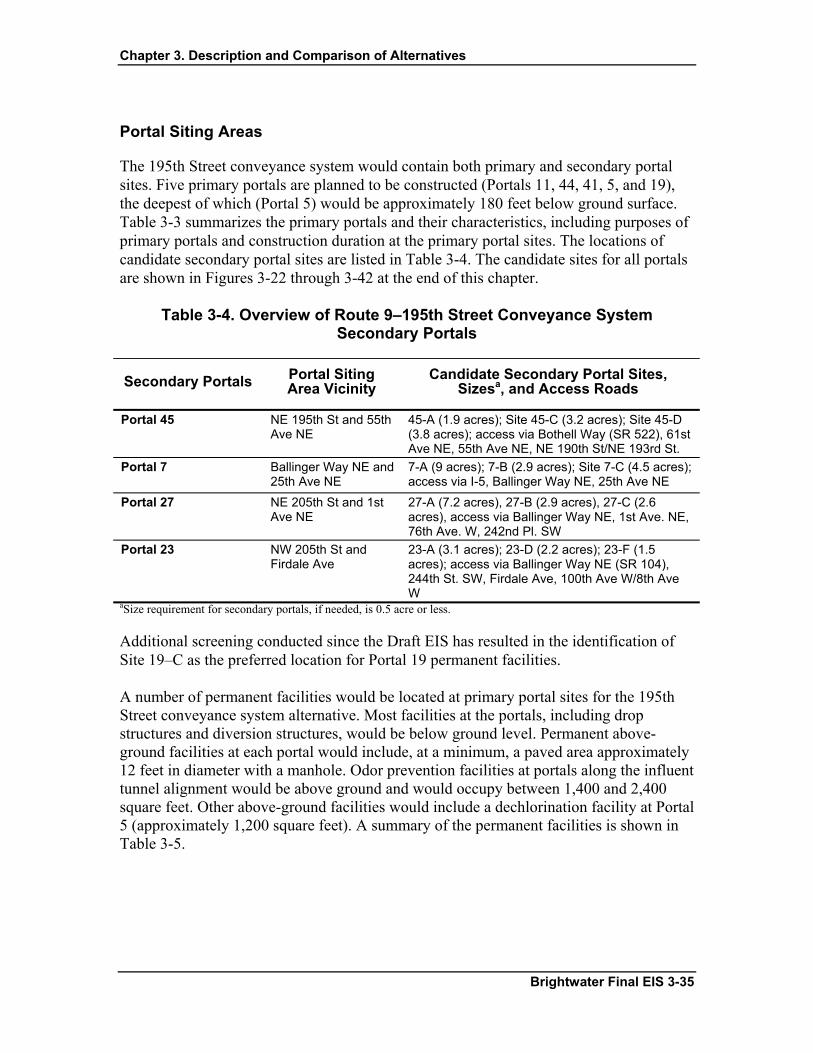
Chapter 3. Description and Comparison of Alternatives
Portal Siting Areas
The 195th Street conveyance system would contain both primary and secondary portal sites. Five primary portals are planned to be constructed (Portals 11, 44, 41, 5, and 19), the deepest of which (Portal 5) would be approximately 180 feet below ground surface. Table 3-3 summarizes the primary portals and their characteristics, including purposes of primary portals and construction duration at the primary portal sites. The locations of candidate secondary portal sites are listed in Table 3-4. The candidate sites for all portals are shown in Figures 3-22 through 3-42 at the end of this chapter.
Table 3-4. Overview of Route 9–195th Street Conveyance System Secondary Portals
Secondary Portals Portal Siting Area Vicinity
Candidate Secondary Portal Sites, Sizesa, and Access Roads
Portal 45
NE 195th St and 55th Ave NE
45-A (1.9 acres); Site 45-C (3.2 acres); Site 45-D (3.8 acres); access via Bothell Way (SR 522), 61st Ave NE, 55th Ave NE, NE 190th St/NE 193rd St.
Portal 7
Ballinger Way NE and 25th Ave NE
7-A (9 acres); 7-B (2.9 acres); Site 7-C (4.5 acres); access via I-5, Ballinger Way NE, 25th Ave NE
Portal 27
NE 205th St and 1st Ave NE
27-A (7.2 acres), 27-B (2.9 acres), 27-C (2.6 acres), access via Ballinger Way NE, 1st Ave. NE, 76th Ave. W, 242nd Pl. SW
Portal 23
NW 205th St and Firdale Ave
23-A (3.1 acres); 23-D (2.2 acres); 23-F (1.5 acres); access via Ballinger Way NE (SR 104), 244th St. SW, Firdale Ave, 100th Ave W/8th Ave W
aSize requirement for secondary portals, if needed, is 0.5 acre or less.
Additional screening conducted since the Draft EIS has resulted in the identification of Site 19–C as the preferred location for Portal 19 permanent facilities.
A number of permanent facilities would be located at primary portal sites for the 195th Street conveyance system alternative. Most facilities at the portals, including drop structures and diversion structures, would be below ground level. Permanent above-ground facilities at each portal would include, at a minimum, a paved area approximately 12 feet in diameter with a manhole. Odor prevention facilities at portals along the influent tunnel alignment would be above ground and would occupy between 1,400 and 2,400 square feet. Other above-ground facilities would include a dechlorination facility at Portal 5 (approximately 1,200 square feet). A summary of the permanent facilities is shown in Table 3-5.
Brightwater Final EIS 3-35
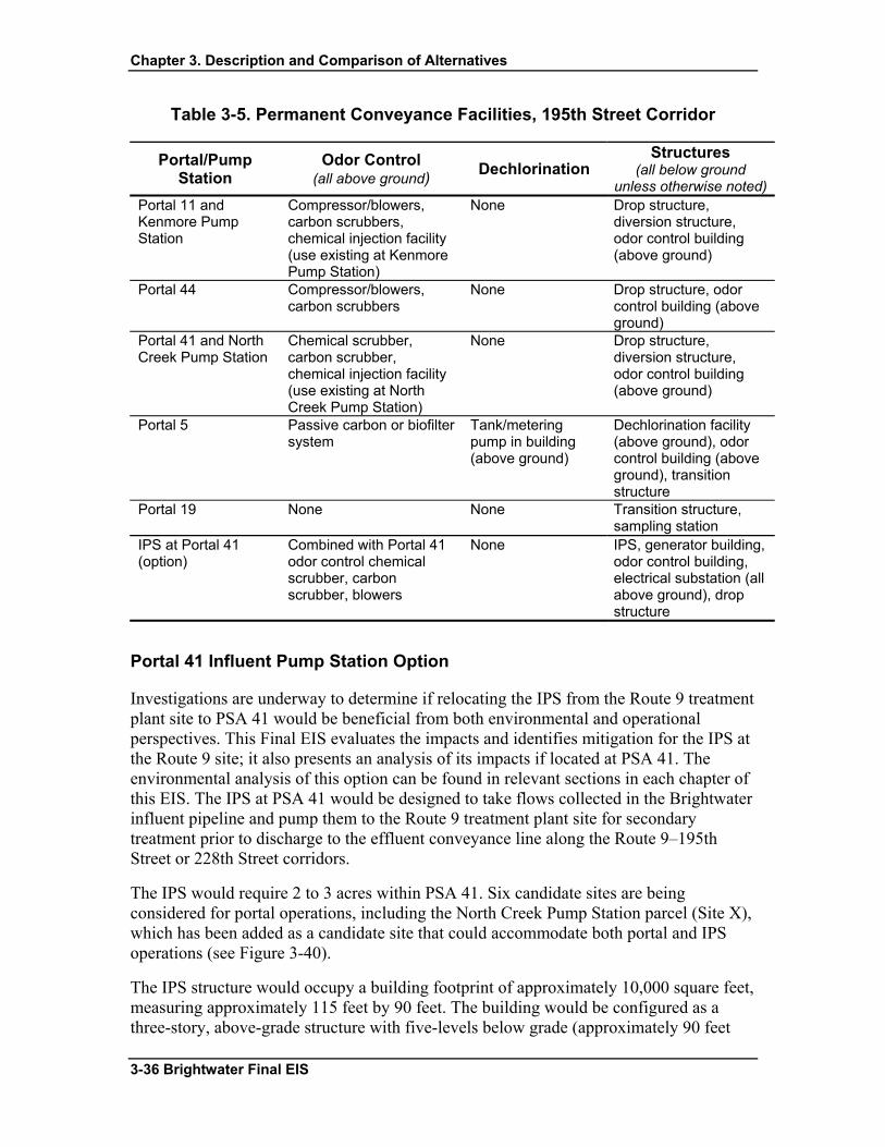
Chapter 3. Description and Comparison of Alternatives
Table 3-5. Permanent Conveyance Facilities, 195th Street Corridor
Portal/Pump Station
Odor Control (all above ground) Dechlorination
Structures (all below ground
unless otherwise noted)Portal 11 and Kenmore Pump Station
Compressor/blowers, carbon scrubbers, chemical injection facility (use existing at Kenmore Pump Station)
None Drop structure, diversion structure, odor control building (above ground)
Portal 44 Compressor/blowers, carbon scrubbers
None Drop structure, odor control building (above ground)
Portal 41 and North Creek Pump Station
Chemical scrubber, carbon scrubber, chemical injection facility (use existing at North Creek Pump Station)
None Drop structure, diversion structure, odor control building (above ground)
Portal 5 Passive carbon or biofilter system
Tank/metering pump in building (above ground)
Dechlorination facility (above ground), odor control building (above ground), transition structure
Portal 19 None None Transition structure, sampling station
IPS at Portal 41 (option)
Combined with Portal 41 odor control chemical scrubber, carbon scrubber, blowers
None IPS, generator building, odor control building, electrical substation (all above ground), drop structure
Portal 41 Influent Pump Station Option
Investigations are underway to determine if relocating the IPS from the Route 9 treatment plant site to PSA 41 would be beneficial from both environmental and operational perspectives. This Final EIS evaluates the impacts and identifies mitigation for the IPS at the Route 9 site; it also presents an analysis of its impacts if located at PSA 41. The environmental analysis of this option can be found in relevant sections in each chapter of this EIS. The IPS at PSA 41 would be designed to take flows collected in the Brightwater influent pipeline and pump them to the Route 9 treatment plant site for secondary treatment prior to discharge to the effluent conveyance line along the Route 9–195th Street or 228th Street corridors.
The IPS would require 2 to 3 acres within PSA 41. Six candidate sites are being considered for portal operations, including the North Creek Pump Station parcel (Site X), which has been added as a candidate site that could accommodate both portal and IPS operations (see Figure 3-40).
The IPS structure would occupy a building footprint of approximately 10,000 square feet, measuring approximately 115 feet by 90 feet. The building would be configured as a three-story, above-grade structure with five-levels below grade (approximately 90 feet
3-36 Brightwater Final EIS

Chapter 3. Description and Comparison of Alternatives
below grade). The structure would be a cast-in-place concrete building with a façade and grounds compatible with the existing neighborhood.
In addition to the pump station structure, it is anticipated that odor control equipment and standby power equipment would be located in separate buildings. The odor control building would be a three-story structure with a footprint of approximately 6,000 square feet designed to also accommodate odor control equipment for portal operation. Depending on site, building, and equipment requirements, the odor control building could be integrated into the pump station structure. A two-story standby power building with a footprint of approximately 11,000 square feet would also be located at this site. An electrical substation occupying approximately 16,000 square feet would be constructed to support pump station operations.
Construction Schedule
The construction duration for major activities is shown in Table 3-3. Additional detail on construction scheduling is provided in Appendix 3-G, Construction Approach and Schedule.
3.2.2.3 Outfall: Route 9–195th Street System
The Route 9 System outfall pipeline in Zone 7S would be about 6,200 feet in length, including approximately 1,000 feet on land and about 5,200 feet offshore. Its discharge depth would be about -600 feet MLLW. The marine outfall would start at the preferred Portal 19 site on the southern edge of the Chevron site at Point Wells, traverse on land to the tip of Point Wells, then continue west into Puget Sound. Three conceptual outfall alignments within this zone were evaluated in the Draft EIS; this alignment (referred to as the Lower Point Wells alignment and shown in Figure 3-9) was identified as the preferred alignment for both the Route 9–195th Street and 228th Street Systems. Its selection was due to the minimal amount of impact to sensitive nearshore habitat when compared to the other potential alignments.
As described previously, open-cut construction is the preferred method for installation of the onshore and nearshore segments of the outfall pipeline along the Lower Point Wells alignment. Open-cut construction methods, as opposed to microtunnel construction methods, are preferred for the installation of the onshore and nearshore segments because impassable barriers, such as piles, logs, and boulders have created difficulties for a significant number of similar land-based tunnel projects in the Puget Sound region. The total construction duration for the outfall and diffuser pipeline is estimated to be 10 to 12 months (not including equipment and material procurement). Nearshore alignments and construction methods are evaluated in Appendix 3-F, Nearshore Construction Methods and Alignment Alternatives.
Open-cut excavation and pipeline installation along the Lower Point Wells alignment would extend approximately 1,000 feet from the conveyance tunnel terminus at Portal 19
Brightwater Final EIS 3-37

Chapter 3. Description and Comparison of Alternatives
to the tip of Point Wells just south of the existing dock. Onshore open-cut construction would use trench sheeting to limit impacts to nearshore plant and animal habitat and to minimize the volume of soils excavated from potentially contaminated areas. Methods to control and contain groundwater, in addition to trench sheeting and dewatering, will be evaluated during final design.
Construction would take place within the existing seawall up to the tip of Point Wells, where the trench would be constructed through the seawall and continue approximately 700 feet through the nearshore to a water depth of approximately –80 feet MLLW. For the nearshore segment, the first 450 feet would be sheeted to a depth of –30 feet MLLW, and the remaining 250 feet would be unsheeted construction. Beyond the open-cut section, the offshore outfall pipeline (4,000 feet) and diffuser segment (500 feet) would be laid on the seafloor to a water depth of approximately –600 feet MLLW. Table 3-6 shows characteristics of the Route 9 outfall alignment.
Table 3-6. Brightwater Outfall Characteristics for Route 9 Alternatives
Characteristic Zone 7S (Route 9)
Outfall length 1,000 feet onshore; 5,200 feet offshore Discharge depth -600 feet MLLW Outfall diameter 60 inches Diffuser length 500 feet Discharge capacity Up to 170 mgd
3.2.3 Route 9–228th Street System
3.2.3.1 Treatment Plant: Route 9–228th Street System
The treatment plant design for the Route 9–228th Street System would be the same as for the 195th Street System.
3.2.3.2 Conveyance System: Route 9–228th Street System
The Route 9–228th Street conveyance system would include the same influent corridor and the same outfall zone as the 195th Street conveyance system. However, the effluent pipeline for the 228th Street system would follow a different alignment (generally along 228th Street SE/SW in Snohomish County) and would have a different set of effluent pipeline portal siting areas, as shown on Figure 3-10. An influent pump station would be located at the Route 9 plant site; because the conveyance system would be a combination of pressure pipelines and gravity system, no other pump stations would be required within the conveyance system. As previously described under the Route 9–195th Street conveyance system, investigations are underway to determine if relocating the planned influent pump station from the Route 9 site to Portal 41 would be beneficial. Characteristics of the 20.3-
3-38 Brightwater Final EIS
Chapter 3. Description and Comparison of Alternatives
mile conveyance system, including approximately 1.8 miles of local connections are described in Table 3-7. The actual length of the local connections depends on the final location of the portal sites.
The majority of the Route 9–228th Street conveyance system would be located in Snohomish County. Affected jurisdictions for the Route 9–228th Street conveyance system (including the influent portion) could include the cities of Woodinville, Bothell, Brier, Kenmore, Lake Forest Park, Shoreline, Mountlake Terrace, and Edmonds; the Town of Woodway; and unincorporated King and Snohomish Counties.
Influent Pipeline
The influent pipeline would follow the same alignment as the NE 195th Street conveyance system, generally following 68th Avenue NE to NE 195th Street, then turning east on 195th Street to Portal 44. The alignment then runs east along NE 195th Street through Portal 41 to SR-522, and then north to the Route 9 site. The influent characteristics would be the same as the 195th Street conveyance system, except that the section of the influent pipeline between Portal 44 and the Route 9 site would not be placed within a combined tunnel with the effluent pipeline since the effluent pipeline follows a different route.
A profile of the 228th Street conveyance system influent tunnel is shown in Figure 3-11. A cross section of the tunnel is shown in Figure 3-12.
Effluent Pipeline
The effluent pipeline for the 228th Street conveyance system would follow the alignment of 228th Street SE/SW from the Route 9 site, passing through primary PSAs 39, 33, and 26 to a point near the intersection of 228th Street SW and 95th Place W. The corridor then would turn south and generally follow 100th Avenue W until intersecting with NW 205th Street. At NW 205th Street, the corridor would head west to Portal 19 and connect to the Zone 7S outfall at Point Wells. The total length of the effluent tunnel alignment is approximately 12.2 miles. Table 3-7 summarizes the 228th Street conveyance system characteristics. A cross section of the tunnels is provided in Figure 3-12. The effluent tunnel profile is shown in Figure 3-13.
Portal Siting Areas
Seven primary portals would be constructed (Portals 11, 44, 41, 39, 33, 26, and 19), the deepest of which would be approximately 200 feet (Portal 26). Table 3-7 contains a summary of the primary portals and construction characteristics associated with the
primary portals. Secondary portal locations are noted on Table 3-8. Portal construction characteristics, shown in the tables, include purposes of primary portals and construction duration at the primary portal sites. The candidate sites are shown in Figures 3-22 through 3-42 at the end of this chapter.
Brightwater Final EIS 3-39
Chapter 3. Description and Comparison of Alternatives
Additional screening conducted since the Draft EIS has resulted in the identification of Site 19–C as the preferred location for Portal 19 permanent facilities.
A number of permanent facilities would be located at primary portal sites for the 228th Street conveyance system alternative. A summary of the permanent facilities is shown in Table 3-9. These facilities would be similar to those discussed for the 195th Street conveyance system alternative. As with the 195th Street conveyance system, a study of the potential to relocate the influent pump station to Portal 41 is currently being considered as an option; permanent facilities associated with the IPS would be the same as described for the Route 9–195th Street alternative.
Construction Schedule
The construction duration for major activities is shown in Table 3-7. Additional detail on construction scheduling is provided in Appendix 3-G, Construction Approach and Schedule.
3.2.3.3 Outfall: Route 9–228th Street System
The outfall within Zone 7S for the 228th Street System would be the same as the 195th Street System.
3-40 Brightwater Final EIS
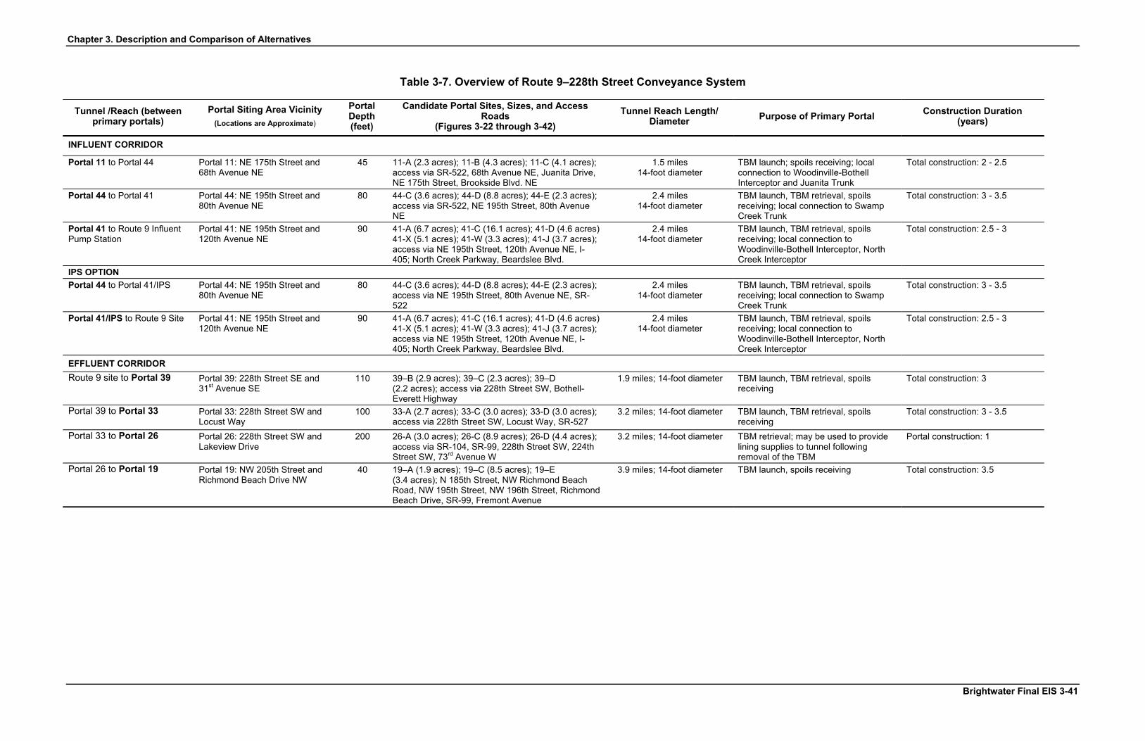
Chapter 3. Description and Comparison of Alternatives
Table 3-7. Overview of Route 9–228th Street Conveyance System
Tunnel /Reach (between primary portals)
Portal Siting Area Vicinity (Locations are Approximate)
Portal Depth (feet)
Candidate Portal Sites, Sizes, and Access Roads
(Figures 3-22 through 3-42) Tunnel Reach Length/
Diameter Purpose of Primary Portal Construction Duration (years)
INFLUENT CORRIDOR
Portal 11 to Portal 44 Portal 11: NE 175th Street and 68th Avenue NE
45 11-A (2.3 acres); 11-B (4.3 acres); 11-C (4.1 acres); access via SR-522, 68th Avenue NE, Juanita Drive, NE 175th Street, Brookside Blvd. NE
1.5 miles 14-foot diameter
TBM launch; spoils receiving; local connection to Woodinville-Bothell Interceptor and Juanita Trunk
Total construction: 2 - 2.5
Portal 44 to Portal 41 Portal 44: NE 195th Street and 80th Avenue NE
80 44-C (3.6 acres); 44-D (8.8 acres); 44-E (2.3 acres); access via SR-522, NE 195th Street, 80th Avenue NE
2.4 miles 14-foot diameter
TBM launch, TBM retrieval, spoils receiving; local connection to Swamp Creek Trunk
Total construction: 3 - 3.5
Portal 41 to Route 9 Influent Pump Station
Portal 41: NE 195th Street and 120th Avenue NE
90 41-A (6.7 acres); 41-C (16.1 acres); 41-D (4.6 acres) 41-X (5.1 acres); 41-W (3.3 acres); 41-J (3.7 acres); access via NE 195th Street, 120th Avenue NE, I-405; North Creek Parkway, Beardslee Blvd.
2.4 miles 14-foot diameter
TBM launch, TBM retrieval, spoils receiving; local connection to Woodinville-Bothell Interceptor, North Creek Interceptor
Total construction: 2.5 - 3
IPS OPTION Portal 44 to Portal 41/IPS Portal 44: NE 195th Street and
80th Avenue NE 80 44-C (3.6 acres); 44-D (8.8 acres); 44-E (2.3 acres);
access via NE 195th Street, 80th Avenue NE, SR-522
2.4 miles 14-foot diameter
TBM launch, TBM retrieval, spoils receiving; local connection to Swamp Creek Trunk
Total construction: 3 - 3.5
Portal 41/IPS to Route 9 Site Portal 41: NE 195th Street and 120th Avenue NE
90 41-A (6.7 acres); 41-C (16.1 acres); 41-D (4.6 acres) 41-X (5.1 acres); 41-W (3.3 acres); 41-J (3.7 acres); access via NE 195th Street, 120th Avenue NE, I-405; North Creek Parkway, Beardslee Blvd.
2.4 miles 14-foot diameter
TBM launch, TBM retrieval, spoils receiving; local connection to Woodinville-Bothell Interceptor, North Creek Interceptor
Total construction: 2.5 - 3
EFFLUENT CORRIDOR Route 9 site to Portal 39
Portal 39: 228th Street SE and 31st Avenue SE
110 39–B (2.9 acres); 39–C (2.3 acres); 39–D (2.2 acres); access via 228th Street SW, Bothell-Everett Highway
1.9 miles; 14-foot diameter TBM launch, TBM retrieval, spoils receiving
Total construction: 3
Portal 39 to Portal 33 Portal 33: 228th Street SW and Locust Way
100 33-A (2.7 acres); 33-C (3.0 acres); 33-D (3.0 acres); access via 228th Street SW, Locust Way, SR-527
3.2 miles; 14-foot diameter TBM launch, TBM retrieval, spoils receiving
Total construction: 3 - 3.5
Portal 33 to Portal 26
Portal 26: 228th Street SW and Lakeview Drive
200 26-A (3.0 acres); 26-C (8.9 acres); 26-D (4.4 acres); access via SR-104, SR-99, 228th Street SW, 224th Street SW, 73rd Avenue W
3.2 miles; 14-foot diameter TBM retrieval; may be used to provide lining supplies to tunnel following removal of the TBM
Portal construction: 1
Portal 26 to Portal 19 Portal 19: NW 205th Street and Richmond Beach Drive NW
40 19–A (1.9 acres); 19–C (8.5 acres); 19–E (3.4 acres); N 185th Street, NW Richmond Beach Road, NW 195th Street, NW 196th Street, Richmond Beach Drive, SR-99, Fremont Avenue
3.9 miles; 14-foot diameter TBM launch, spoils receiving Total construction: 3.5
Brightwater Final EIS 3-41

Chapter 3. Description and Comparison of Alternatives
THIS PAGE INTENTIONALLY LEFT BLANK
3-42 Brightwater Final EIS
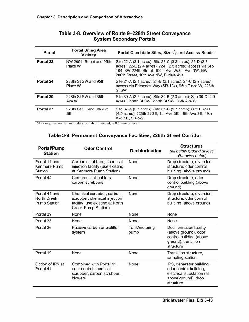
Chapter 3. Description and Comparison of Alternatives
Table 3-8. Overview of Route 9–228th Street Conveyance System Secondary Portals
Portal Portal Siting Area Vicinity
Portal Candidate Sites, Sizesa, and Access Roads
Portal 22
NW 205th Street and 95th Place W
Site 22-A (3.1 acres); Site 22-C (3.3 acres); 22-D (2.2 acres); 22-E (2.4 acres); 22-F (2.5 acres); access via SR-104, SW 224th Street, 100th Ave W/8th Ave NW, NW 200th Street, 10th Ave NW, Firdale Ave
Portal 24
228th St SW and 95th Place W
Site 24-A (2.4 acres); 24-B (2.1 acres); 24-C (2.2 acres); access via Edmonds Way (SR-104), 95th Place W, 228th St SW
Portal 30
228th St SW and 35th Ave W
Site 30-A (2.5 acres); Site 30-B (2.0 acres); Site 30-C (4.9 acres); 228th St SW, 227th St SW, 35th Ave W
Portal 37
228th St SE and 9th Ave SE
Site 37-A (2.7 acres); Site 37-C (1.7 acres); Site E37-D (4.5 acres); 228th St SE, 9th Ave SE, 19th Ave SE, 19th Ave SE, SR-527
aSize requirement for secondary portals, if needed, is 0.5 acre or less.
Table 3-9. Permanent Conveyance Facilities, 228th Street Corridor
Portal/Pump Station
Odor Control Dechlorination
Structures (all below ground unless
otherwise noted) Portal 11 and Kenmore Pump Station
Carbon scrubbers, chemical injection facility (use existing at Kenmore Pump Station)
None Drop structure, diversion structure, odor control building (above ground)
Portal 44 Compressor/bubblers, carbon scrubbers
None Drop structure, odor control building (above ground)
Portal 41 and North Creek Pump Station
Chemical scrubber, carbon scrubber, chemical injection facility (use existing at North Creek Pump Station)
None Drop structure, diversion structure, odor control building (above ground)
Portal 39 None None None Portal 33 None None None Portal 26 Passive carbon or biofilter
system Tank/metering pump
Dechlorination facility (above ground), odor control building (above ground), transition structure
Portal 19 None None Transition structure, sampling station
Option of IPS at Portal 41
Combined with Portal 41 odor control chemical scrubber, carbon scrubber, blowers
None IPS, generator building, odor control building, electrical substation (all above ground), drop structure
Brightwater Final EIS 3-43
Chapter 3. Description and Comparison of Alternatives
3.2.4 Unocal System
3.2.4.1 Treatment Plant: Unocal System
As with the Route 9 alternatives, a Brightwater treatment plant constructed at Unocal would be designed to treat 36 mgd of wastewater by 2010 with features to allow for a future expansion to 54 mgd in 2040. The plant would use the same split-flow MBR secondary treatment process to meet secondary discharge requirements for release of disinfected effluent to Puget Sound.
Two sub-alternatives relating to the Unocal site also have been evaluated. One sub-alternative involves treating flows from the Cities of Edmonds and Lynnwood at the Brightwater Treatment Plant, potentially expanding the capacity of the plant from 54 to 72 mgd in 2040. The other sub-alternative involves building a structural “lid” over a part of the treatment plant site to accommodate a proposed multimodal transportation facility (Edmonds Crossing). The multimodal lid sub-alternative would be designed to allow construction of the proposed Edmonds Crossing project and could be incorporated into the design and construction of either the 54 mgd alternative or the 72 mgd sub-alternative. Table 3-10 provides an overview of the Unocal treatment facilities.
Site Location and Layout
Site Location and Characteristics The Unocal site is located in the City of Edmonds, just southeast of the Port of Edmonds Marina (Figure 3-14). The overall site includes the area east and west of the Burlington Northern-Santa Fe Railroad tracks and the right-of-way for Pine Street, which would be relocated to accommodate the treatment plant. The small triangular piece of land along the shoreline west of the railroad includes a marsh and public beach along Puget Sound. The treatment plant would be built on the larger triangular piece of land east of the railroad tracks. Willow Creek and a wetland occupy the east perimeter of this larger piece of land, and the railroad runs along its west perimeter. The Deer Creek Hatchery is located in the southeast corner. Residences lie to the south and southeast.
3-44 Brightwater Final EIS

Chapter 3. Description and Comparison of Alternatives
Table 3-10. Overview of Unocal Treatment Facilities
Features Phase 1 (2010, 36 mgd)
Phase 2 (2040, 54 mgd)
72 mgd Sub-
Alternative Sub-Alternative
with lid
Physical Characteristics Site size 52.6 acres 52.6 acres 52.6 acres 52.6 acres
Facility footprint (area affected by construction)
34.5 acres 34.5 acres with MBR; 39.0 acres with CAS
34.7 acres; 41.3 acres with CAS
39.1 acres for 72 mgd with lid
Impervious surface area
22 acres 23 acres with MBR; 25 acres with CAS and Class A biosolids
24 acres with MBR; 26 acres with CAS and Class A biosolids
28 acres for 72 mgd with lid
Site access Primary vehicle access from Edmonds Way (SR 104) to Pine Street
Same as Phase 1 Same as Phase 1
Same as Phase 1
Local government with jurisdiction
City of Edmonds City of Edmonds City of Edmonds
City of Edmonds
Treatment Process Characteristics Liquids treatment Split-flow MBR with
ballasted sedimentation for flows above split threshold
Same as Phase 1, with option to convert to CAS if necessary
Same as Phase 2
Same as Phase 2 or 72 mgd sub-alternative (depending on plant capacity)
Solids treatment Thickening, anaerobic digestion, dewatering, and hauling for Class B biosolids. Space reserved for Class A biosolids.
Same as Phase 1 with additional facilities to treat 54 mgd Class A
Same as Phase 1 with additional facilities to treat 72 mgd
Same as Phase 2 or 72 mgd sub-alternative (depending on plant capacity)
Reclaimed water 5 mgd Class A reclaimed water for on-site use; UV disinfection
Up to 54 mgd Class A reclaimed water for on- and offsite use; UV disinfection
Same as Phase 2; UV disinfection
Same as Phase 2; UV disinfection
Average annual flow
31 mgd 47 mgd 62 mgd Same as Phase 2 or 72 mgd sub-alternative (depending on plant capacity)
Average wet-weather flow
36 mgd 54 mgd 72 mgd Same as Phase 2 or 72 mgd sub-alternative (depending on plant capacity)
Brightwater Final EIS 3-45

Chapter 3. Description and Comparison of Alternatives
Table 3-10. Overview of Unocal Treatment Facilities (cont.)
Features Phase 1 (2010, 36 mgd)
Phase 2 (2040, 54 mgd)
72 mgd Sub-
Alternative Sub-Alternative
with lid
Treatment Process Characteristics (cont.) MBR Split-flow 38 mgd 56 mgd 76 mgd Same as Phase 2
or 72 mgd sub-alternative (depending on plant capacity)
Peak hydraulic capacity
130 mgd 170 mgd 235 mgd Same as Phase 2 or 72 mgd sub-alternative (depending on plant capacity)
Odor control Decentralized odor control with 3-phase chemical scrubbing followed by carbon polishing
Same as Phase 1 Same as Phase 1
Same as Phase 1
Disinfection 38 mgd UV disinfection for MBR effluent; sodium hypochlorite for peak flows
56 mgd UV disinfection, sodium hypochlorite disinfection for peak flows
76 mgd UV disinfection, sodium hypochlorite disinfection for peak flows
Same as Phase 2 or 72 mgd sub-alternative (depending on plant capacity)
Other Onsite Facilities Influent pump station
Pumps wastewater from influent tunnel to headworks for preliminary treatment
Same as Phase 1 Same as Phase 1
Same as Phase 1
Effluent pump station
Pumps treated wastewater to Puget Sound through outfall and diffuser
Same as Phase 1 Same as Phase 1
Same as Phase 1
Reuse distribution pump station
Sized for 5 mgd onsite use; potential to increase according to demand
Up to 54 mgd onsite use depending on demand
Same as Phase 2
Same as Phase 2
Non-process structures
Administration building, maintenance facility, chemical storage building, cogeneration
Same as Phase 1 Same as Phase 1
Same as Phase 1
3-46 Brightwater Final EIS

Chapter 3. Description and Comparison of Alternatives
Table 3-10. Overview of Unocal Treatment Facilities (cont.)
Features Phase 1 (2010, 36 mgd)
Phase 2 (2040, 54 mgd)
72 mgd Sub-
Alternative Sub-Alternative
with lid
Other Onsite Facilities (cont.) Parking 80 total spaces Same as Phase 1 Same as
Phase 1 Same as Phase 1
Stormwater management
Stormwater wet pond at northern corner of the site, north of maintenance building; discharge to new outfall at –50 MLLW, located in same trench as effluent outfall
Same as Phase 1 Same as Phase 1
Same as Phase 1
Cogeneration Biogas and natural gas to generate sufficient power to run facility at AWWF; 7 MW
Same as Phase 1; 13 MW
Same as Phase 1; 16 MW
Same as Phase 1; 16 MW
Operational Features Number of employees
47 to 52 67 to 75 90 to 100 Same as Phase 2 or 72 mgd sub-alternative depending on plant capacity
Work hours by shift
33 to 39 day shift employees for WWTP, 12 employees on 12-hour shifts (4 crews)
41 to 49 day shift employees for WWTP; 24-26 employees on 12-hour shifts (4 crews)
53 to 65 day shift em-ployees for WWTP; 35-37 employees on 12-hour shifts (4 crews)
Same as Phase 2 or 72 mgd sub-alternative depending on plant capacity
Truck trips per week (solids removal and chemical deliveries)
50 one-way trips 74 one-way trips 96 one-way trips
Same as Phase 2 or 72 mgd sub-alternative
Average connected energy demand (including influent and effluent pump stations and Portal 11 pump station)
8.7 MW
14.8 MW 17.6 MW Same as Phase 2 or 72 mgd sub-alternative
Biosolids production
76.4 cubic yards/day at AWWF
114.6 cubic yards/day at AWWF
152.8 cubic yards/day at AWWF
Same as Phase 2 or 72 mgd sub-alternative
Brightwater Final EIS 3-47

Chapter 3. Description and Comparison of Alternatives
Table 3-10. Overview of Unocal Treatment Facilities (cont.)
Features Phase 1 (2010, 36 mgd)
Phase 2 (2040, 54 mgd)
72 mgd Sub-
Alternative Sub-Alternative
with lid
Construction Durationa Site preparation (includes demolition, mobilization, and structural excavation)
26 months (early 2005 to mid-2007)
To be developed at a later date
To be developed at a later date
See below
Facilities construction
42 months (late 2006 to mid-2010)
To be developed at a later date
To be developed at a later date
Foundation for lid must be constructed concurrent with Phase 1 facilities; lid structure could be completed by 2010 subject to funding
Plant startup and commissioning
16 months (mid-late 2009 to late 2010)
To be developed at a later date
To be developed at a later date
See above
Total Construction 70 months (early 2005 to late 2010)
To be developed at a later date
To be developed at a later date
See above
aTotal construction duration is not the sum of the individual activities because some construction activities take place at the same time.
The 52.6-acre site is situated on a hillside adjacent to Puget Sound. Due to the slope, treatment facilities would be constructed using a series of retaining walls and terraces. The effluent would be discharged through an outfall directly west of the plant into Puget Sound. Stormwater runoff from the site would be directed to a water quality pond at the lowest elevation on the west side of the site, where it would be treated and subsequently discharged directly to Puget Sound. No detention would be required at Unocal because discharge directly to Puget Sound eliminates the need for flood control.
The Unocal Corporation owns the part of the site east of the railroad tracks. The City of Edmonds owns the small portion of the site west of the tracks. Unocal used the southern part of the property for storing, blending, and distributing various petroleum products, including gasoline, diesel fuel, and bunker fuel. The northern part of the site was used for asphalt production between 1953 and the late 1970s. Abandoned oil tanks and underground storage tanks that occupied the site were removed in 2001. A small pier in Puget Sound, connected to the southwest part of the site, was formerly used to unload oil through pipelines from ships to the Unocal facility. The property west of the railroad tracks currently is used as public parkland.
3-48 Brightwater Final EIS
Chapter 3. Description and Comparison of Alternatives
The Unocal site has confirmed soil and groundwater contamination originating from 70 years of industrial activities. Unocal is conducting investigation and cleanup of contamination under an order from the Washington State Department of Ecology.
The topography of the Unocal site rises from north to south and west to east. The wetland areas on the northern portion of the site are relatively flat, transitioning to a hillside that slopes steeply to the south and east. The grade of the slope ranges from 0 to 40 percent over the majority of the site, generally the northern and eastern portions, and from 40 to 80 percent over the remaining, generally western, part of the site.
A deep foundation system would be required for the facilities in the lower yard of the Unocal site. This system would be needed to resist buoyancy due to high groundwater and to provide support in liquefiable soils. A preliminary structural analysis was performed to determine the number of piles required. The conceptual foundation design for the structures in the lower yard of the Unocal site is shown in Appendix 3-A, Project Description: Treatment Plant.
Site Preparation Because of its unique characteristics, the Unocal site would require more preparation for construction than the Route 9 site. If remediation of existing onsite contamination has not occurred prior to property transfer, remediation would need to take place at the beginning of the construction period. Depending on the nature and extent of contamination, it is anticipated that all remaining contaminated materials would be removed from the site for offsite treatment at licensed facilities. Due to the varying grade at the site, the plant would be constructed on two levels, an upper and a lower site area. Significant excavation would be necessary to achieve the required grade, resulting in removal of a total of 1.6 million cubic yards of soil. Due to the character of the onsite soils, it is anticipated that these soils will not be suitable for use as fill material in other areas of the site and, therefore, would require export and disposal offsite. The 1.6 million cubic yards of spoils would be hauled offsite during the construction period, and approximately 500,000 cubic yards of fill material would be imported to the site.
A significant element of the Unocal site preparation would be construction of retaining walls and graded roadways to provide slope stabilization and facilitate access. The retaining walls would form three terraces at approximate elevations of 125, 95, and 20 feet above sea level. The total area of the retaining walls would be approximately 375,000 square feet, requiring about 28,000 cubic yards of concrete. In addition to the retaining walls, it may be necessary to construct a temporary cutoff wall along the north-northwest end of the site to protect the marsh and creek to the north during excavation and construction of facilities in the lower yard.
Construction of the basic 36/54 mgd treatment plant at the Unocal site would not require rerouting of nearby streams or fishery-related facilities (i.e., the Deer Creek hatchery). However, to enhance habitat for salmon, Willow Creek, which runs through the Edmonds Marsh, would be “daylighted.” This involves removing the creek from the long culvert
Brightwater Final EIS 3-49

Chapter 3. Description and Comparison of Alternatives
through which it currently runs under the railroad tracks between the marsh and the Puget Sound shoreline and allowing it to flow aboveground. Daylighting of the creek would eliminate a barrier to fish passage and improve habitat in the marsh.
Site Layout A conceptual design for the treatment plant on the Unocal site is shown in Figure 3-15. The layout includes 1.6 acres of the Pine Street right-of-way that would be relocated along the southern property line. The total footprint of the treatment and support facilities at full buildout in 2040 would be approximately 34.5 acres for the base alternative. If the 72-mgd sub-alternative were constructed without a multimodal lid, the treatment plant would occupy 34.7 acres, with an additional 6.6 acres reserved for expansion to full flow CAS and Class A biosolids. The 72 mgd sub-alternative with the multimodal lid would occupy a footprint of 39 acres.
A 50- to 75-foot setback between the treatment process units and the southern property line would provide a buffer for residents to the south; greater buffers would be provided between the treatment facilities and Willow Creek on the north side of the plant, although less buffer would be available along parts of the west side. Because of the steep slopes, a series of retaining walls would be constructed in a stepwise fashion to terrace the site for construction of the treatment units and to allow for reasonable road grades. For example, the preliminary treatment facilities and solids handling facilities would be placed on the 125-foot level; the entrance and administration building would be on the 95-foot level; and the secondary treatment and reuse treatment facilities would be located on the lower, northern part of the site. The terraces installed during the first phase of construction for the 36-mgd treatment plant would provide sufficient room for addition of the individual treatment process units required for the 54-mgd expansion and the 72-mgd sub-alternative. The additional area for the expanded plant would be in the vicinity of the secondary treatment and reuse facilities.
Edmonds Way (SR-104) provides the main road access to the site on the hillside and lower site east of the railroad. Pine Street runs along the site’s southern boundary and into the Unocal property. Pine Street would be relocated along the southern property line of the site. Details of the Pine Street relocation are presented in Appendix 3-A, Project Description: Treatment Plant.
The Unocal alternative does not include a potential onsite community-oriented building on the site itself as could be provided on the Route 9 site. This is because of the tighter site constraints and the potential other sub-alternatives that could use the remaining space available.
Sub-Alternatives
There are two sub-alternatives being considered for the Unocal site. One is to accept additional wastewater flow from the Cities of Edmonds and Lynnwood for a total
3-50 Brightwater Final EIS

Chapter 3. Description and Comparison of Alternatives
treatment plant capacity of 72 mgd in 2040. The other sub-alternative is to construct a structural “lid” over a portion of the treatment plant to accommodate the Edmonds Crossing multimodal facility.
Sub-Alternative: Treat Edmonds and Lynnwood Flows at the Unocal Site There are two existing wastewater treatment plants in the City of Edmonds. One plant, operated by the City of Lynnwood, is located at the far north end of Edmonds. The other plant, operated by the City of Edmonds, is located about one-half mile from the Unocal site in downtown Edmonds. Edmonds and Lynnwood are not part of the King County Service Area, however, King County currently operates under a flow transfer agreement with Edmonds, which outlines the transfer and treatment of limited quantities of wastewater from each service area by each utility. Treating flows from Edmonds and Lynnwood would require expanding the Brightwater plant to 72-mgd to provide capacity for Phase 2 (2040).
As described above, the Brightwater Treatment Plant would be constructed in at least two phases: (1) an initial phase providing capacity to treat up to 36 mgd in 2010, and (2) a later expansion through addition of treatment components in about 2040 to increase the capacity to 54 mgd. Should Edmonds and/or Lynnwood decide, either now or at a later date, to close their plants and transfer the flows to the Brightwater plant, those transfers could be accommodated by expanding Brightwater. The site layout for the 72-mgd plant is shown in Figure 3-16. Sufficient area is available on site to expand the plant to 72-mgd capacity using the split-flow MBR treatment process. However, if the 72-mgd plant were converted to full flow CAS, the secondary clarifiers would encroach on the eastern wetlands and Willow Creek.
The outfall for the Brightwater plant at Unocal would be sized to convey and discharge the full potential flows, including Edmonds and Lynnwood. Neither Edmonds nor Lynnwood has formally expressed an interest in treating their flows at the Brightwater plant; however, if in the future Edmonds or Lynnwood decides to pursue flow transfer, appropriate environmental review would be required to evaluate the effects of installing pipelines to convey the flows to the Brightwater plant. The impacts of a 72-mgd treatment plant at the Unocal site are evaluated in this Final EIS.
Sub-Alternative: Construct a Structural Lid Over the Treatment Plant at the Unocal Site to Accommodate the Edmonds Crossing Multimodal Facility Another sub-alternative for the Unocal site is to construct a structural “lid” over the northern portion of the site that could accommodate the proposed multimodal transportation facility, Edmonds Crossing. The multimodal facility would include ferry access and other facilities as described in the SR 104 Edmonds Crossing, Draft Environmental Impact Statement and Draft Section 4(f) Evaluation (1998). The multimodal facility layout would need to be revised somewhat to be oriented along the retaining walls of the treatment plant. In addition, all transportation facilities would be located on the multimodal lid, with grade-separated access to commuter rail platforms and stations. The multimodal facility would provide 580 parking spaces, vehicle drop-off
Brightwater Final EIS 3-51

Chapter 3. Description and Comparison of Alternatives
and pick-up area along the western perimeter of the multimodal lid, and transit lanes and loading berths at ferry and commuter rail linkage points. The Unocal multimodal lid sub-alternative would also provide pedestrian access to neighboring roads and the Deer Creek hatchery. The decision to include a multimodal lid would need to be made before beginning final design of the treatment plant so that the design and construction of the lid and treatment facilities could be coordinated with the Washington Department of Transportation.
A preliminary site layout for the full-buildout, 72-mgd treatment plant is shown with the multimodal lid in Figure 3-17. The multimodal lid would cover a majority of the secondary processes, including the fine screens, aeration basins, MBR tanks, membrane support building, and the space reserved for CAS secondary clarifiers, as well as the maintenance building, reuse facilities, and a portion of the effluent pump station.
Structural support for the multimodal lid would consist of deep piles and support columns, beams, and girders. The spacing for the piles and columns would vary depending on the configuration of the tankage and buildings below the multimodal lid. In areas where tanks and buildings are rectangular, piles and columns would be integrated into walls and footings in a grid pattern to coincide with the tank and building dimensions. In areas of circular structures, where long spans are required, piles and columns would be independent of the structure and would be located around the perimeter of the tankage. Preliminary conceptual foundation and support plans and details are presented in Attachment K of Appendix 3-A, Project Description: Treatment Plant.
Construction Schedule
The active construction phase of the Phase 1 treatment plant would last slightly less than 5 years overall, from March 2005 to January 2010. The durations of key construction activities are shown in Table 3-10. A more detailed construction schedule is provided in Appendix 3-G, Construction Approach and Schedule, along with a detailed description of construction for the sub-alternative that includes a structural lid.
Construction of the combined base alternative and lid would require extended work hours for construction of the foundation in order to meet the 2010 target date for startup of the treatment plant.
3.2.4.2 Conveyance System: Unocal System
The Unocal conveyance system would include an influent pipeline to carry wastewater from King County's existing pipelines in Bothell and Kenmore to the Unocal site (Figure 3-18). Because the treatment plant would be located adjacent to Puget Sound and the outfall zone, the Unocal plant effluent would be conveyed directly to the outfall so no separate effluent conveyance system would be needed.
3-52 Brightwater Final EIS

Chapter 3. Description and Comparison of Alternatives
Influent Pipeline
The Unocal conveyance system would begin in the vicinity of the existing North Creek Pump Station at Portal 14, immediately northeast of the interchange of SR-522 and Interstate-405, and would generally follow a cross-country path to Portal 11 in the vicinity of the existing Kenmore Pump Station. From there, the corridor would generally follow Bothell Way (SR-522) and Ballinger Way NE (SR-104) through Portal 7 to NE 205th Street, then follow NE 205th Street to Edmonds Way (SR-104) through Portal 3 and on to the Unocal site. The approximate length of the corridor would be 11.6 miles, excluding local connections, most of which would be in King County. The length of local connections for the Unocal conveyance system would be approximately 1 mile depending on the final location of the portal sites.
The conveyance system would be a gravity system between Portal 14 and Portal 11. A new pump station near the existing Kenmore Pump Station in Portal Siting Area 11 would be required to pump the wastewater uphill to Portal 7. The tunnel would be constructed at a grade that roughly follows the ground surface between Portals 11 and 7, thereby minimizing the required depths for the portals. The conveyance system would convert back to a gravity system between Portal 7 and the Unocal site. An influent and an effluent pump station would be required on the Unocal site.
A profile of the influent tunnel is shown in Figure 3-19. Figure 3-20 shows a cross-section of the tunnels. Specific elements of the Unocal conveyance system are shown in Table 3-11.
Portal Siting Areas
The Unocal conveyance system would include primary and secondary portal sites. Four primary portals would be constructed (Portals 14, 11, 7, and 3), the deepest of which would be approximately 280 feet (Portal 3). Table 3-11 summarizes the primary portals and construction characteristics, including purposes of primary portals and construction duration at the primary portal sites. Secondary portals are identified in Table 3-12. The candidate sites are shown in Figures 3-22 through 3-42 at the end of this chapter.
A number of permanent facilities would be located at primary portal sites for the Unocal conveyance system. Most facilities at the portals, including drop structures and diversion structures, would be below ground level. Permanent above-ground facilities at each portal would include, at a minimum, a paved area approximately 12 feet in diameter with a manhole. Odor prevention facilities at portals along the influent tunnel alignment would be above ground and would occupy between 3,400 and 4,400 square feet. A summary of the permanent facilities is shown in Table 3-13.
Brightwater Final EIS 3-53
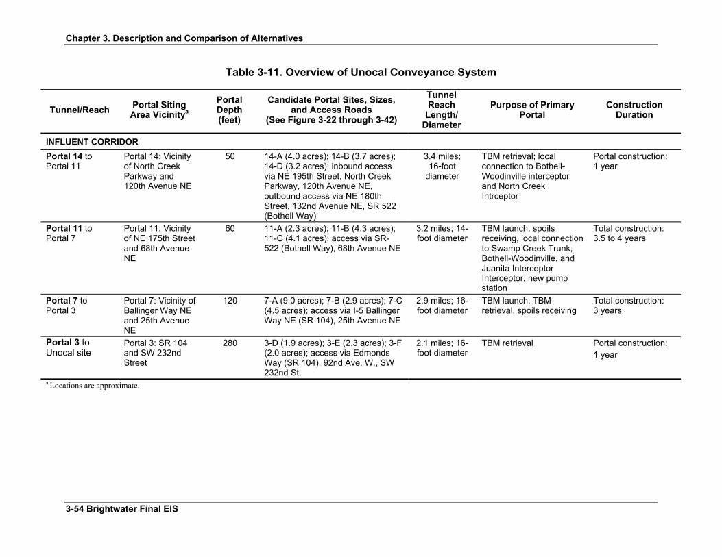
Chapter 3. Description and Comparison of Alternatives
Table 3-11. Overview of Unocal Conveyance System
Tunnel/Reach Portal Siting Area Vicinitya
Portal Depth (feet)
Candidate Portal Sites, Sizes, and Access Roads
(See Figure 3-22 through 3-42)
Tunnel Reach
Length/ Diameter
Purpose of Primary Portal
Construction Duration
INFLUENT CORRIDOR Portal 14 to Portal 11
Portal 14: Vicinity of North Creek Parkway and 120th Avenue NE
50 14-A (4.0 acres); 14-B (3.7 acres); 14-D (3.2 acres); inbound access via NE 195th Street, North Creek Parkway, 120th Avenue NE, outbound access via NE 180th Street, 132nd Avenue NE, SR 522 (Bothell Way)
3.4 miles; 16-foot
diameter
TBM retrieval; local connection to Bothell-Woodinville interceptor and North Creek Intrceptor
Portal construction: 1 year
Portal 11 to Portal 7
Portal 11: Vicinity of NE 175th Street and 68th Avenue NE
60 11-A (2.3 acres); 11-B (4.3 acres); 11-C (4.1 acres); access via SR-522 (Bothell Way), 68th Avenue NE
3.2 miles; 14-foot diameter
TBM launch, spoils receiving, local connection to Swamp Creek Trunk, Bothell-Woodinville, and Juanita Interceptor Interceptor, new pump station
Total construction: 3.5 to 4 years
Portal 7 to Portal 3
Portal 7: Vicinity of Ballinger Way NE and 25th Avenue NE
120 7-A (9.0 acres); 7-B (2.9 acres); 7-C (4.5 acres); access via I-5 Ballinger Way NE (SR 104), 25th Avenue NE
2.9 miles; 16-foot diameter
TBM launch, TBM retrieval, spoils receiving
Total construction: 3 years
Portal 3 to Unocal site
Portal 3: SR 104 and SW 232nd Street
280 3-D (1.9 acres); 3-E (2.3 acres); 3-F (2.0 acres); access via Edmonds Way (SR 104), 92nd Ave. W., SW 232nd St.
2.1 miles; 16-foot diameter
TBM retrieval Portal construction: 1 year
a Locations are approximate.
3-54 Brightwater Final EIS

Chapter 3. Description and Comparison of Alternatives
New Kenmore Pump Station
A new influent pump station would be required if the Unocal System is selected. The influent pump station would be located in Portal Siting Area 11, near the site of the existing Kenmore Pump Station. The pump station would be sized for a peak capacity of 170 mgd and would contain the following functional components:
• Pump station (12,000 square feet in area, 20 – 35 feet tall)
• Odor control equipment (4,400 square feet in area)
• Standby power (4,500 square feet in area)
• Electrical substation (16,000 square feet in area)
Construction Schedule
The construction duration for major activities is shown in Table 3-11. Additional detail on construction scheduling is provided in Appendix 3-G, Construction Approach and Schedule.
Table 3-12. Overview of Unocal Conveyance System Secondary Portals
Portal Portal Siting Area (Vicinity of Intersections)
Candidate Portal Sites, Sizesa, and Access Roads
Portal 13 Bothell Way NE and Woodinville Drive
13-A (2.0 acres); 13-B (3.0 acres); Site 13-C (2.7 acres); access via Bothell Way/Woodinville Dr.(SR-522),
Portal 12 NE 183rd Street and 80th Avenue NE
12-C (3.1 acres); 12-E (2.1 acres); access via NE Bothell Way (SR 522), NE 175th St., 73rd Ave NE
Portal 10 NE 178th Street and 44th Avenue NE
10-A (5.6 acres); 10-C (3.8 acres); 10-D (4.0 acres); 10-E (1.7 acres); access via Bothell Way (SR-522), 44th Ave NE, Ballinger Way NE (SR 104), NE 178th St, Brookside Blvd NE
Portal 5 NE 205th Street and Ballinger Way NE
5-B (3.3 acres); 5-G (1.8acres); 5-X (1.0 acres); access via Ballinger Way NE (SR 104), 15th Ave NE,
a Size requirement for secondary portals, if needed, is 0.5 acre or less.
Brightwater Final EIS 3-55
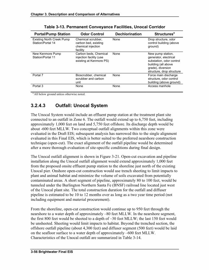
Chapter 3. Description and Comparison of Alternatives
Table 3-13. Permanent Conveyance Facilities, Unocal Corridor Portal/Pump Station Odor Control Dechlorination Structuresa
Existing North Creek Pump Station/Portal 14
Chemical scrubber, carbon bed, existing chemical injection facility
None Drop structure, odor control building (above ground)
New Kenmore Pump Station/Portal 11
Carbon beds, Chemical injection facility (use existing at Kenmore PS)
None New pump station, generator, electrical substation, odor control building (all above grade), diversion structure, drop structure
Portal 7 Bioscrubber, chemical scrubber and carbon unit
None Force main discharge structure, odor control building (above ground)
Portal 3 None None Access manhole
a All below ground unless otherwise noted.
3.2.4.3 Outfall: Unocal System
The Unocal System would include an effluent pump station at the treatment plant site connected to an outfall in Zone 6. The outfall would extend up to 6,750 feet, including approximately 1,000 feet on land and 5,750 feet offshore. Its discharge depth would be about -600 feet MLLW. Two conceptual outfall alignments within this zone were evaluated in the Draft EIS; subsequent analysis has narrowed this to the single alignment evaluated in this Final EIS, which is better suited to the preferred nearshore construction technique (open-cut). The exact alignment of the outfall pipeline would be determined after a more thorough evaluation of site-specific conditions during final design.
The Unocal outfall alignment is shown in Figure 3-21. Open-cut excavation and pipeline installation along the Unocal outfall alignment would extend approximately 1,000 feet from the proposed onsite effluent pump station to the shoreline just north of the existing Unocal pier. Onshore open-cut construction would use trench sheeting to limit impacts to plant and animal habitat and minimize the volume of soils excavated from potentially contaminated areas. A short segment of pipeline, approximately 80 to 100 feet, would be tunneled under the Burlington Northern Santa Fe (BNSF) railroad line located just west of the Unocal plant site. The total construction duration for the outfall and diffuser pipeline is estimated to be 10 to 12 months over as long as a two year time period (not including equipment and material procurement).
From the shoreline, open-cut construction would continue up to 950 feet through the nearshore to a water depth of approximately –80 feet MLLW. In the nearshore segment, the first 800 feet would be sheeted to a depth of –30 feet MLLW; the last 150 feet would be unsheeted. Sheeting would limit impacts to habitat. Beyond the trenched section, the offshore outfall pipeline (about 4,300 feet) and diffuser segment (500 feet) would be laid on the seafloor surface to a water depth of approximately –600 feet MLLW. Characteristics of the Unocal outfall are summarized in Table 3-14.
3-56 Brightwater Final EIS

Chapter 3. Description and Comparison of Alternatives
Table 3-14. Brightwater Outfall Characteristics for Unocal Alternative
Characteristic Zone 6 (Unocal)
Outfall length 1,000 feet onshore; up to 5,750 feet offshore Discharge depth -600 feet MLLW Outfall diameter 60 inches Diffuser length 500 feet Discharge capacity 18 to 170 mgd (235 mgd for 72 mgd sub-alternative)
3.2.5 No Action Alternative King County is required under the State Environmental Policy Act (SEPA) to evaluate a “No Action Alternative.” In other words, what would be the impacts to the environment if the Brightwater System were not built? This section describes the implications of not building the Brightwater System.
As population in the region grows, wastewater flows will increase. The Regional Wastewater Services Plan (RWSP) determined that as flows reach the capacity of the two existing plants, a new treatment plant would be needed to treat wastewater from the northern part of the service area. Under the No Action Alternative, King County would not implement the part of the RWSP that calls for construction of a third wastewater treatment plant. The No Action Alternative is one in which the increasing wastewater flows would continue to be treated at one of the two existing King County treatment plants—the South Plant in Renton and the West Point Plant in Seattle. These plants, and the pipelines that convey wastewater to them, will reach capacity in about 2010. If Brightwater is built by 2010, flows from the north part of the service area that would otherwise go to the South Treatment Plant or the West Point Treatment Plant would be redirected to Brightwater. This would provide capacity at the existing plants to treat wastewater flows from the southern and eastern portions of the Service Area, which are also experiencing growth in population.
If the Brightwater System is not built, the increasing flows from all parts of the Service Area would continue to go to the existing plants, and the increasing volume would ultimately exceed the capacity of the plants and conveyance system to treat the wastewater. There would be a strong likelihood that wastewater would overflow into the local environment whenever volumes exceeded the combined capacity of the two treatment plants and conveyance system, thereby greatly increasing the risk of environmental health hazards and the potential of degrading the quality of local streams, rivers, and lakes. This situation would put King County out of compliance with its NPDES permit and violate the Clean Water Act and possibly other laws. Please refer to Appendix 3-J, Evaluation of the No Action Alternative.
Although No Action would provide no new capacity to treat flows from the north end of the Service Area, other RWSP programs and projects would be implemented under the No Action Alternative. This would include expanding the South Plant in Renton to
Brightwater Final EIS 3-57

Chapter 3. Description and Comparison of Alternatives
provide an additional 20 mgd of capacity in 2029 and beyond. King County would also continue implementing a combined sewer overflow program to reduce the volume of excess untreated wastewater discharged during storm events into the Lake Washington Ship Canal, the Duwamish River, and Puget Sound. King County could continue its program to improve and expand portions of the regional conveyance system; however continuing to add conveyance capacity without corresponding treatment capacity between 2010 and 2029 would result in more sanitary sewer overflows and violations of NPDES permits. King County also would continue to implement its program to control the amount of infiltration and inflow (groundwater and stormwater) that enters the conveyance pipelines through cracked pipes, leaky joints, manhole covers, and illegal connections such as storm and roof drains. The Industrial Waste and Household Hazardous Waste programs would continue to improve the quality of wastewater and biosolids, and King County would look for opportunities to recycle and reuse reclaimed water.
While these programs would help to maintain the wastewater system and provide additional environmental protection in some areas, they would not eliminate the need to construct additional conveyance and treatment capacity for increasing wastewater flows in the north end of the Service Area. Significant degradation of the environment and potential to harm public health would begin to occur in 2010 as a result of untreated wastewater overflows. This impact could be limited if the Washington State Department of Ecology were to impose a moratorium on building throughout the King County Service Area. To protect public and environmental health, such a moratorium would need to be in place no later than 2005 or 2006 to account for building permits already in process.
Specific impacts of the No Action Alternative on the environment, such as impacts to environmental health, water quality, and fish habitat, are evaluated in detail in subsequent chapters of this Final EIS and in Table No. EP 2-9 of the RWSP EIS, which is incorporated by reference into this EIS (King County, 1998).
3.3 Comparing the Alternatives This section compares the three Brightwater System action alternatives. It focuses on environmental impacts that are likely to remain after the proposed mitigation has been integrated into the site selection process and into facility and site design. The Brightwater proposal includes the application of innovative engineering and the selection of appropriate construction methods and techniques for each project component. The alternatives also are compared after assuming implementation of mitigation included in the Brightwater proposal, such as enhancements to the environment and to the communities affected by the construction and operation of Brightwater. Key features of the Brightwater alternatives are described in Table 3-15. This comparison of alternatives also highlights construction impacts that are, although temporary, of sufficient intensity and duration to be considered here.
3-58 Brightwater Final EIS

Chapter 3. Description and Comparison of Alternatives
Table 3-15. Comparison of Key Features of the Brightwater Alternatives
Characteristics Route 9–195th Street System Route 9–228th Street System Unocal System Treatment Plant
Capacity (average wet weather flow) • 36 mgd in 2010 (Phase 1) • 54 mgd in 2040 (Phase 2)
• 36 mgd in 2010 (Phase 1) • 54 mgd in 2040 (Phase 2)
• 36 mgd in 2010 (Phase 1) • 54 mgd in 2040 (Phase 2) • 72 mgd in 2040 if flows from Edmonds and Lynnwood are included
Site size 114 acres 114 acres 53 acres Plant footprint (area affected by construction) 43 acres for split-flow MBR; 48 acres for 54 mgd facility if converted to
conventional activated sludge (CAS) 43 acres for split-flow MBR; 48 acres for 54 mgd facility if converted to CAS • 35 acres (36 mgd)
• 35 acres (54 mgd; 39 acres if CAS treatment is used) • 39 acres (72 mgd w/flows from Edmonds and Lynnwood)
Liquids treatment Primary and MBR with split flow ballasted primary clarification for sustained peak flows
Primary and MBR with split flow ballasted primary clarification for sustained peak flows
Primary and MBR with split flow ballasted primary clarification for sustained peak flows
Solids treatment Anaerobic digestion with Class B biosolids; space reserved for future production of Class A biosolids
Anaerobic digestion with Class B biosolids; space reserved for future production of Class A biosolids
Anaerobic digestion with Class B biosolids; space reserved for future production of Class A biosolids
Effluent disinfection Sodium hypochlorite in effluent tunnel Sodium hypochlorite in effluent tunnel Ultraviolet (UV) for MBR effluent; sodium hypochlorite for split flow disinfection; both on-site
Reclaimed water UV disinfection to produce 5 mgd of Class A reclaimed water in Phase 1, up to 54 mgd in Phase 2
UV disinfection to produce 5 mgd of Class A reclaimed water in Phase 1, up to 54 mgd in Phase 2
UV disinfection to produce 5 mgd of Class A reclaimed water in Phase 1, up to 54 mgd in Phase 2
Pump stations Influent only Influent only Influent and effluent Influent Conveyance Corridor Total Length 8.1 miles (including 1.8 miles of local connections and 4.8 miles of combined tunnel
section)a, b 8.1 miles (including 1.8 miles of local connections) b 11.6 miles (excluding local connections, which are expected to be approximately 1
mile) b Primary Portal siting areas
• Portal 11 - NE 175th St & 68th Ave NE • Portal 44 – NE 195th St & 80th Ave NE • Portal 41 - NE 195th St & 120th Ave NE
• Portal 11 - NE 175th St & 68th Ave NE • Portal 44 - NE 195th St & 80th Ave NE • Portal 41 - NE 195th St & 120th Ave NE
• Portal 14—North Creek Pkwy & 120th Ave NE • Portal 11—NE 175th St & 68th Ave NE • Portal 7—Ballinger Way NE & 25th Ave NE • Portal 3—SR 104 & SW 232nd St
Construction options Gravity flow for the entire length; potential for some force mains if IPS is located at Portal 41
Gravity flow for the entire length; potential for some force mains if IPS is located at Portal 41
• A combination of gravity flow (from Portal 14 to Portal 11 and from Portal 7 to Portal 3) and force main flow (from Portal 11 to Portal 7)
Pump stations Potential for new influent pump station to be located at Portal 41 instead of at treatment plant
Potential for new influent pump station to be located at Portal 41 instead of at treatment plant
• One new pump station at Portal 11 near the existing Kenmore Pump Station • Modify the North Creek Pump Station
Safety relief point(s) Lower Sammamish River in Kenmore Lower Sammamish River in Kenmore Lower Sammamish River in Kenmore and Unocal WWTP effluent outfall Effluent Conveyance Corridor Total Length 7.8 miles (plus 4.8 miles of combined tunnel section)a 12.2 miles N/A Primary Portal siting areas • Portal 41—NE 195th St & 120th Ave NE
• Portal 44—NE 195th St & 80th Ave NE • Portal 5—NE 205th St & Ballinger Way NE • Portal 19—NW 205th St & Richmond Beach Dr NW
• Portal 39—228th St SE & 31st Ave SE • Portal 33—228th St SW & Locust Way • Portal 26—228th St SW & Lakeview Dr • Portal 19—NW 205th St & Richmond Beach Dr NW
N/A
Construction options • Combination of gravity flow and pressure flow • A combination of gravity flow and pressure flow N/A Pump stations • None
• None
N/A
Outfall Alignment Outfall Zone 7S
• Trench alignment (preferred) Outfall Zone 7S
• Trench alignment (preferred) Outfall Zone 6
• Trench alignment (preferred) Length and depth Approximately 6,200 feet; 600 feet below mean lower low water Approximately 6,200 feet; 600 feet below mean lower low water Approximately 6,750 feet; 600 feet below mean lower low water Affected Jurisdictions Cities of Woodinville, Bothell, Kenmore, Lake Forest Park, and Shoreline; Town of
Woodway; unincorporated King and Snohomish Counties Cities of Bothell, Brier, Mountlake Terrace, Edmonds, Shoreline, Woodinville, Kenmore; Town of Woodway; unincorporated King and Snohomish Counties
Cities of Edmonds, Mountlake Terrace, Shoreline, Lake Forest Park, Kenmore, and Bothell; Town of Woodway; unincorporated King and Snohomish Counties
aTotal length of 195th Street influent and effluent conveyance routes plus local connections is 15.9 miles. b The total length of influent local connections depends on the actual location of the portal sites.
Brightwater Final EIS 3-59

Chapter 3. Description and Comparison of Alternatives
THIS PAGE INTENTIONALLY LEFT BLANK
3-60 Brightwater Final EIS
Chapter 3. Description and Comparison of Alternatives
Specific features of the comparison are as follows:
• Assumes that all major direct and indirect probable significant adverse impacts to the environment have been mitigated for each of the three action alternatives to the greatest extent feasible.
• Compares alternative systems—Route 9–195th Street System, Route 9–228th Street System, and Unocal System—in their entirety as systems so that the tradeoffs among the types of impacts and the extent and location of the impacts can be understood.
• Focuses to a certain extent on the two proposed treatment plant locations, where appropriate. Construction at these sites would cover large areas and would have an extended duration compared to construction of conveyance facilities. The operating treatment plant would become a permanent part of the community with a greater magnitude of long term impacts than would be generated by permanent conveyance facilities.
• Compares the potential impacts that would result from constructing conveyance portals for alternative systems and the impacts of constructing and operating wastewater tunnels.
• Acknowledges that because of the large scope and scale of the proposal and the area that it covers, there are circumstances where an overall system comparison alone may not be the most useful analysis of site-specific impacts. For example, the environmental impacts experienced at one treatment plant site for one element of the environment such as earth, may be clearly more significant than at the other treatment plant location, yet impacts associated with constructing the conveyance may offset any overall distinguishable difference and these impacts may be experienced in multiple neighborhoods.
• Includes both construction impacts and permanent operation impacts for the Brightwater facilities. Although some facilities, such as primary tunnel portals, may not result in significant permanent changes to the environment, the magnitude and duration of the construction impacts warrant including them as the alternative systems are compared.
This comparison of alternatives does not identify or consider all environmental impacts that could be generated by the proposed project. Because mitigation is included as an integral part of the Brightwater proposal, many aspects of constructing and operating the facilities produce similar impacts regardless of the location. Although evaluated in other chapters of the FEIS, where impacts are essentially the same for each alternative, they are not considered in this section as distinguishing features and are therefore not essential information in comparing alternatives. Chapters 4 through 17 each conclude with a table listing all direct and indirect significant impacts and proposed mitigation that provides a comprehensive summary for each element of the environment.
The No Action Alternative is not included in this Chapter 3 comparison of alternatives because it has already been addressed in great detail under each element of the
Brightwater Final EIS 3-61
Chapter 3. Description and Comparison of Alternatives
environment; further discussion here does not assist decision makers in comparing the action alternatives. The No Action Alternative has been analyzed as required by WAC 197-11-440 (5) (c) (vi) and compared with the action alternatives in the text and summary tables in Chapters 4 through 17 of this Final EIS.
The Final EIS includes substantial documentation that the No Action Alternative may not be a viable course of action as compared to any of the action alternatives, given its identified adverse impacts on the environment and public health.
3.3.1 Overall Comparison of Impacts for Alternative Components and Systems
3.3.1.1 Treatment Plant Sites
Operational characteristics at either the Route 9 or Unocal site would be comparable. Treatment plant siting and design for both sites have focused on mitigating potential operation impacts, including odor, potential for chemical release, and water quality and habitat degradation from stormwater discharges to freshwater systems and effluent discharge to the marine environment. Thus, operating a treatment plant at either the Route 9 or Unocal location can be considered to have comparable impacts regarding operations noise, odor, air emissions, meeting stormwater treatment requirements, and generation of vehicle and truck traffic. The quality of effluent and reclaimed water produced at each potential treatment plant would be comparable.
Both sites can be expanded to the ultimate planned capacity of 54-mgd, and both would provide reclaimed water for onsite uses. Although not part of this proposal, the plants would in the future have the potential to provide reclaimed water at a volume dependent on the demand. The potential demands within 5 miles of the plant sites and the effluent portion of the Route 9–195th Street effluent corridor are different, with 7.4 mgd projected for Unocal and 10.1 mgd for the Route 9 system. The Sammamish Valley has a concentration of irrigation customers that could also be served by Brightwater in the near term. The potential demand for up to an additional 10 mgd could lead to significant improvement of conditions in the Sammamish River. By replacing uses that draw directly from the river with reclaimed water, the river could have more water available to support fish populations, particularly in the warmer months of the year. The Sammamish Valley could be served by either plant, but at a lesser cost from the Route 9–195th Street System.
Both sites have reserved space to accommodate new types of wastewater and solids treatment technologies in the future. This includes space for the facilities that would be needed to produce Class A biosolids.
The method of disinfection is somewhat different between the Route 9 and Unocal Systems. Because the Route 9 site is much farther inland from Puget Sound than the
3-62 Brightwater Final EIS

Chapter 3. Description and Comparison of Alternatives
Unocal site, sodium hypochlorite would be added to the effluent as it enters the conveyance tunnel to prevent regrowth of pathogens as the flow travels to the outfall in Puget Sound. A dechlorination facility is required for the Route 9 systems, proposed to be located at Portal 5, to remove residual chlorine before the effluent is discharged to Puget Sound in compliance with State Water Quality Standards. For the Unocal site, the treatment plant is located so near the outfall that there is no effluent conveyance system. The disinfection method for the Unocal system is proposed to occur at the treatment plant site and consist of ultraviolet light (UV) for the MBR effluent and sodium hypochlorite for the split flow. Dechlorination would occur onsite at a Unocal treatment plant prior to discharge into Puget Sound.
Route 9 Site
The design of the Route 9 site may provide greater opportunities to mitigate the impacts of constructing and operating the treatment plant than does the Unocal site, primarily because the Route 9 site is larger and is located in a less densely developed setting. There are wider buffers between the proposed facilities and surrounding land uses and the development density in the immediate vicinity of the Route 9 site is relatively low. This creates a greater natural separation between the public and the treatment plant during construction and operation.
Concerns have been raised about the potential for significant adverse impacts to the Cross Valley Aquifer from constructing and operating the Brightwater treatment plant at the Route 9 site. Extensive geotechnical studies have been undertaken to investigate the physical relationship between the aquifer, surface waters, and the facilities. Results of these studies indicate water quality impacts to the aquifer are not likely because the Route 9 site is down-gradient from the aquifer and dewatering would have minimal impacts to the groundwater levels at Cross Valley wellheads. Water from dewatering would be discharged to Little Bear Creek without significantly altering streamflows. With respect to potential drawdown from dewatering, the aquifer can be adequately protected by a combination of engineering techniques, facility design, and operational safeguards.
Because the Route 9 site is larger than the Unocal site, it provides onsite staging areas for construction activities. There is a greater area for stockpiling earth, storing materials, and providing for construction worker parking at the construction site. This provides more flexibility in how construction is sequenced and implemented, resulting in a greater opportunity to mitigate impacts through such techniques as scheduling truck traffic and avoiding routinely long construction hours.
The Route 9 site also provides the opportunity for long-term mitigation benefits to the natural environment that cannot be provided on the Unocal site. Previous and existing land uses at the Route 9 site were developed piecemeal, over time. Several of them were built prior to environmental regulations protective of water and habitat quality in Little Bear Creek. Because these land uses would be relocated, many of the pre-existing natural
Brightwater Final EIS 3-63
Chapter 3. Description and Comparison of Alternatives
resources on the site that have already been altered and/or degraded over time would be restored and enhanced to provide significant improvements to aquatic and upland habitat.
Unocal Site
Although feasible as a permanent treatment plant location, the Unocal site presents more complex construction challenges than the Route 9 site. The site is smaller and more steeply sloped than Route 9, necessitating a more compact and less flexible site design and comparatively less opportunity for onsite mitigation or enhancement of natural resources. The site, and ultimately the treatment plant, would be relatively close to and very visible from a more densely developed surrounding community than at Route 9.
The steep slope of the Unocal site would require extensive excavation and terracing to accommodate treatment facilities. A very large quantity of earth would have to be removed from the site. Although the Unocal conveyance system is the shortest of the three alternatives and has the fewest portals, the smaller amount of earth excavated for the Unocal portals and tunnel does not offset the extensive plant site alteration and resulting earth movement and transport when compared with the Route 9 systems (see Earth below).
The site is also restricted by the supporting transportation system, including the need to accommodate periodic “pulses” of offloading ferry traffic. Site size and transportation factors also would affect construction scheduling and sequencing that may result in longer work hours, the need to bus workers to the site, and specific transportation mitigation measures to prevent increased truck traffic from interfering with Washington State ferry traffic and other local vehicle traffic.
The Unocal site offers significant regional partnership opportunities that the Route 9 site does not in terms of allowing regional facilities to be consolidated. The Brightwater plant at the Unocal site has been conceptually designed to be co-located with the Washington State Department of Transportation’s Edmonds Crossing project.
The treatment plant at the Unocal site could be expanded to 72-mgd capacity (with or without the Edmonds Crossing project) so that the Edmonds and/or Lynnwood treatment facilities could send their flows to Brightwater at some time in the future if desired by the local wastewater districts. This provides the potential to consolidate treatment facilities and to eliminate two existing shallow water outfalls in Puget Sound offshore of Edmonds by relocating their discharge to the new deepwater outfall, with a corresponding improvement in water quality.
3-64 Brightwater Final EIS

Chapter 3. Description and Comparison of Alternatives
3.3.1.2 Conveyance Corridors
Conveyance systems are compared in terms of three parameters: total length of the tunnels (including the combined influent and effluent tunnel for the Route 9–195th Street System), the number of primary portals, and the location of primary portals.
Conveyance corridor characteristics are as follows:
• The Route 9–195th Street conveyance corridor is a total of 15.9 miles long (including approximately 1.8 miles of local connections) and has five primary portal siting areas.
• The Route 9–195th Street conveyance corridor with an influent pump station at Portal 41 would be the same as above, plus one offsite pump station.
• The Route 9–228th Street conveyance corridor is a total of 20.3 miles long (including approximately 1.8 miles of local connections) and has seven primary portal siting areas.
• The Route 9–228th Street conveyance corridor with an influent pump station at Portal 41 would be the same as above, plus one offsite pump station.
• The Unocal conveyance corridor is a total of 11.6 miles (excluding approximately 1 mile of local connections) and has four primary portal siting areas. Includes one offsite pump station at Portal 11.
Overall, the Route 9–228th Street conveyance corridor has the greatest potential for creating adverse environmental impacts because it is the longest and has the most primary portals and the most portals located in residential areas, where construction impacts are expected to be most strongly experienced. The Route 9–195th Street corridor is the next longest and has five primary portals, but only one is located in a residential neighborhood. The Unocal conveyance corridor would have the fewest primary portals because it is the shortest route and has only minor local connections; however, two portals are located in areas more densely developed with homes and businesses.
Because tunneling is the preferred construction method, the length and diameter of conveyance pipes directly relates to the volume of earth that must be excavated and hauled from primary portals and the amount of groundwater that must be managed overall. Tunneling concentrates the impacts at a few primary portal locations for a longer duration than does linear surface excavation, which extends impacts along the length of the alignment but for shorter periods at any one location.
The number and location of primary portals determine the magnitude of impacts resulting from constructing and operating the conveyance system. Construction activities would be concentrated at primary portal sites for a period of up to several years depending on the purpose of the portal and length and diameter of tunnel it supports. Construction activities at the primary portals are related to excavating and stabilizing the portal shaft and tunnel
Brightwater Final EIS 3-65

Chapter 3. Description and Comparison of Alternatives
and installing permanent piping. The removal of large quantities of earth from the primary portals would result in temporary impacts such as noise, dust and combustion emissions, truck traffic, handling of dewatered groundwater, and erosion and sedimentation. The activities are similar for all tunnel boring machine (TBM) launching portals. Impacts vary primarily by duration of construction and proximity of sensitive receptors.
Although the Draft EIS and Final EIS conduct a thorough evaluation of the significant impacts and possible mitigation measures for secondary portals, secondary portals are not discussed in this comparison of alternatives because their use is still speculative. If secondary portals are used, their purposes are very different, resulting in construction activities and environmental impacts that are of a substantially lesser order of magnitude than those that would be experienced at primary portals. Secondary portals would require smaller construction sites (0.5 acre compared with 1-2 acres for primary portals) have a portal diameter that is less than 8 feet compared with 50 feet for a primary portal and construction activities would generally be completed within a much shorter period of time.
As with the treatment plants, selection of portal sites is key to the type and location of environmental impacts. Two or more specific 2-acre (approximate) candidate portal sites have been identified within each 72-acre primary portal siting area for each system alternative. Site selection criteria designed to avoid or minimize environmental impacts were used to identify the candidate sites and would continue to be used to select the final location where a portal would be constructed. Therefore, individual candidate portal sites are not compared in this summary because there is still sufficient latitude to avoid significant adverse environmental impacts during portal site selection.
Concerns have been raised about potential adverse risks to groundwater quality and quantity where the conveyance tunnel would pass through major aquifers that are sources of public drinking water (Cross Valley Aquifer, Olympic View Water and Sewer District, and Lake Forest Park Water District). Geotechnical investigations and engineering solutions, such as secondary lining in sensitive aquifer areas, have reduced the potential for significant adverse impacts to aquifers such that all systems alternatives have comparable risks that can be managed with known and tested design and construction techniques.
3.3.1.3 Outfalls
Both proposed outfall zones, Zone 6 for Unocal and Zone 7S for the Route 9 systems, were selected after extensive study of the Puget Sound environment. There is no discernible difference in the environmental impacts of operating the outfalls in either zone. Both zones are considered equal in their ability to disperse effluent into Puget Sound at a depth and location sufficient to meet Washington State Water Quality Standards. Potential benefits associated with elimination of the outfalls for the Edmonds
3-66 Brightwater Final EIS

Chapter 3. Description and Comparison of Alternatives
and Lynnwood treatment plants under the 72 mgd sub-alternative for the Unocal treatment plant are not evaluated in this Final EIS.
Impacts associated with constructing the outfalls are also similar except for potential adverse impacts to eelgrass and to recreation. Eelgrass provides valuable habitat for a variety of marine species, including protected salmonids. Less eelgrass would be impacted at Zone 7S because of the sparse and patchy eelgrass distribution in the nearshore, as compared with Zone 6. Due to the proximity of the Zone 6 outfall to areas of intense human use, construction of the outfall and diffuser could impact recreational activities and require temporary restrictions to public access to the shoreline and temporary removal of some parking spaces associated with Marina Beach Park.
3.3.2 Comparison of Environmental Impacts by Element of the Environment
3.3.2.1 Earth
The Unocal System would be expected to have substantially greater impacts to earth resources than either of the Route 9 Systems.
Mitigation for earth impacts has focused on balancing cuts and fills while buffering plant views at the Route 9 and Unocal treatment plant sites, designing the tunnel to limit portal depths to the extent possible, factoring seismic sensitivity on the project area into the design, avoiding liquefaction areas where practicable and engineering appropriate foundations where not, and providing retaining walls to stabilize hillsides. Seismic sensitivity at plant sites and along tunnel routes is an integral factor in design.
Adverse impacts associated with excavating soil and removing (exporting) it from or bringing (importing) it to a site are manifested primarily as truck traffic, noise, air quality, dust, combustion emissions, sediment-laden runoff, and construction duration. The volumes of earth projected to be moved for the Brightwater project include both soil export and soil import.
The Route 9–228th Street System would result in the least impacts to earth resources of all the action alternatives. It would require moving approximately 1.27 million cubic yards of earth (soil import and export for the entire system). The Route 9–195th Street System with the option of locating the influent pump at Portal 41 would result in only slightly more impacts to earth resources by requiring the movement of a total of 1.3 million cubic yards. The Route 9–195th Street System (with the IPS at the Route 9 site) would involve the import and export of 1.42 million cubic yards of soil. The Unocal System would require the greatest movement of soil (2.75 million cubic yards), nearly twice the volume of any other alternative.
Brightwater Final EIS 3-67
Chapter 3. Description and Comparison of Alternatives
The option of locating the influent pump station at Portal 41, which King County is considering, would eliminate an extremely deep shaft and would reduce the excavation volumes at the Route 9 site (as noted above). Although the impacts of removing earth would be relocated from the Route 9 site to Portal 41, the portal shaft would not need to be as deep as would be required at the treatment plant site.
Comparing the volume of earth that would need to be moved on the Unocal site or on the Route 9 site demonstrates an important difference between these sites. Because of its steep slope and smaller site size, the Unocal plant site would need to be terraced to accommodate all the plant facilities. This excavation and terracing at the Unocal site would require the movement of 2.1 million cubic yards of earth at the treatment plant itself, whereas 460,000 cubic yards of earth would need to be moved at the Route 9 site.
Both treatment plant locations have the potential for liquefaction; however, there is a greater potential for adverse impacts to facilities at the Unocal site than at the Route 9 site. Because of the type and thickness of liquefaction-susceptible soil at the Unocal site, a more stringent liquefaction mitigation method is necessary that would require structures in the lower yard to be supported on deep foundation pilings. Because the Route 9 site is larger and because of the planned site regrading, liquefaction impacts can be more easily mitigated. At the Route 9 site, three mitigation approaches would be used that would not be feasible at the Unocal site: (1) critical structures can be placed outside or beneath the potential zone of liquefaction, (2) planned site regrading can remove significant quantities of the liquefaction susceptible soils, and (3) stable foundation surfaces can be provided by over-excavating potentially liquefiable soils and then recompacting them.
Both treatment plant sites have known or suspected soil contamination present. The Unocal site has been the subject of a state-listed hazardous waste site cleanup effort for remediating contamination in the upper yard. Cleanup actions in the lower yard still need to be determined and implemented. Preliminary evaluations of the Route 9 site indicate a potential for contamination based on past and present land uses and activities at the site. Until the extent of soil contamination is known, it is difficult to make a quantitative comparison between the Route 9 site and the known contamination problems at the Unocal site.
For conveyance, impacts from excavation at the primary portals would depend on the duration of construction, which would be determined by the function of the portal (whether for launching or recovery of the tunnel boring machine). For launching portals, where soil from tunneling is removed, the impacts would be greatest. The relative quantities of the amount of earth that would need to be removed (or exported) from portals because of conveyance construction are as follows: Route 9–195th Street requires the most earth exported from the portals (911,040 cubic yards), Route 9–228th Street conveyance requires 755,040 cubic yards, and the Unocal conveyance, because it is the shortest, requires the least soil removal (588,390 cubic yards).
While most of the Route 9 conveyance corridors pass through residential areas where there is little potential for significant contamination, both Route 9 conveyance routes end at Portal 19 where there is documented contamination at the Chevron Richmond Beach
3-68 Brightwater Final EIS
Chapter 3. Description and Comparison of Alternatives
Asphalt Terminal property that would require remediation. There is less likelihood that the Unocal conveyance corridors will encounter significantly contaminated soils than will the Route 9 conveyance corridors. There is a greater potential for environmental impacts resulting from excavating and handling contaminated soils from the Route 9 conveyance alternatives than from the Unocal conveyance alternative.
Other than excavation at portals, adverse impacts to the earth’s surface from tunneling are not expected. Unlike open-cut methods where the earth’s surface is directly disturbed, tunneling would occur at sufficient depth to avoid major impacts. Local connections would have minor disturbances. Overall, the Unocal conveyance would be expected to have the least impact to earth resources because it has the shortest distance, least number of portals less local connections when compared with the Route 9 conveyance alternatives. (The Route 9–228th corridor has slightly less earth resources impacts than Route 9–195th corridor because it has the least earthwork excavation, although it has the most portals.)
For all systems, the preferred method for constructing the outfall through the nearshore is the open-cut construction method with trench sheeting to a minimum of –30 feet MLLW. Sheeting would reduce the overall excavated volumes in this area. The remainder of the open-cut portion from –30 to –80 feet MLLW would not be sheeted and would require more material to be excavated to provide stable trench walls.
Impacts to earth resources as a result of constructing or operating the outfall at either Zone 6 or Zone 7S would be comparable.
3.3.2.2 Air
Overall, the potential for creating significant adverse impacts to air resources from implementing any of the Brightwater systems is low, and a difference among the alternatives relative to air quality is not apparent.
Environmental impacts related to air emissions and odor during operation of the system would be sufficiently mitigated such that there would be no real difference among the alternatives. All permanent treatment and conveyance facilities would be designed to operate at a level resulting in no detectable odor at the property boundary and that would meet all federal, state, and local air quality permits. The mitigation includes enclosing facilities, applying best available control technologies (BACT), and controlling all point sources for both odor and air contaminants.
Given the odor control systems proposed for all facilities, the escape of uncontrolled or untreated odors is unlikely and would occur only in rare circumstances such as multiple equipment failures. The meteorological conditions at both sites have been studied and the information has been incorporated into this Final EIS. If multiple equipment failure were to happen, the Route 9 site would be preferable to the Unocal site for reducing the potential impact of off-site odors because of the greater buffer distance from the process units to the property line. At the Unocal site, there would be less than 50 feet between the
Brightwater Final EIS 3-69
Chapter 3. Description and Comparison of Alternatives
process units on the upper terrace and the property line. If an uncontrolled escape of odors were to occur, there could be more temporary adverse air quality impacts at the Unocal site because of its proximity to areas with public access. If the structural lid (with the multimodal facility) sub-alternative is implemented in the future, the potential for adverse air quality impacts could be exacerbated. This scenario is highly unlikely, however, because of the extensive mitigation incorporated into the project to assure that air quality is not adversely affected.
Construction impacts would be different at the two treatment plant sites relative to air resources. Because of the greater site disturbance at Unocal and the larger quantities of earth to be excavated, there is a greater potential for air quality impacts resulting from fugitive dust at Unocal than at the Route 9 site. There is known contamination of soil in the lower yard at the Unocal site that would require special handling to prevent contaminants from becoming airborne. Although the Route 9 site also has suspected contamination, the potential for resulting adverse air quality impacts is probably less severe, and the larger size of the site affords a greater buffer between the construction activities and the site boundary. Adverse impacts resulting from handling contaminated soils can be successfully mitigated at either site.
For conveyance, the Unocal system has the least number of primary portals (four) and therefore fewer construction sites to generate construction air quality impacts such as dust and combustion pollutants. However, two of these primary portal siting areas are in residential areas where sensitive receptors (homes) may be closer to the portals and thus more likely to experience impacts from construction dust. The Route 9–195th Street System has five primary portals, one more portal than Unocal, but only one primary portal siting area is in a residential neighborhood. The Route 9–228th Street system has three primary portals in residential neighborhoods. Air impacts of operating any of the proposed conveyance systems are considered to be comparable because of the odor prevention measures that would be employed.
Impacts to air resources resulting from constructing and operating the outfall would be comparable regardless of whether Zone 6 or Zone 7S is selected at the outfall location.
3.3.2.3 Water Resources
Groundwater
All of the alternatives have a negligible to low overall potential for significant adverse environmental impacts to groundwater when proposed mitigation measures are implemented. The differences among the alternatives with respect to groundwater impacts cannot be summed up on a “system-wide” basis because there are too many site-specific factors and unique circumstances for each project component to reach a general conclusion. The following information highlights the tradeoffs among components and alternatives, where possible.
3-70 Brightwater Final EIS

Chapter 3. Description and Comparison of Alternatives
Construction of either treatment plant site would require dewatering. Contaminated groundwater is likely or expected to be encountered at either treatment plant location and at Portal 19 at Point Wells. However, treating and disposing of contaminated groundwater is a routine part of construction and does not present a distinguishing feature when comparing environmental impacts among alternatives.
Drawdown has been modeled for each plant site, and no significant adverse impacts to aquifers are anticipated that cannot be mitigated. Dewatered groundwater can be discharged safely back into natural systems at both potential treatment plant locations. Because of known and suspected groundwater contamination at the Unocal site, however, more extensive groundwater quality treatment would likely be necessary before the dewatered groundwater could be discharged into the Edmonds Marsh, an important function to maintain water levels in the marsh during construction. For this reason and because of the potential drawdown of water levels in Edmonds Marsh, construction of a treatment plant at the Unocal site would present a greater risk from dewatering. Although manageable, this situation would require careful monitoring and contingency planning to avoid impacts during construction.
Development of the Route 9 site for the treatment plant would require operation of a permanent underdrain system to intercept groundwater from the shallow unconfined aquifer and lower the groundwater table locally around structures. Groundwater removed by the permanent underdrains is not expected to result in adverse impacts to any water resources, including private and public walls systems, as the drawdown will be localized and flow will be reintroduced to the shallow aquifer. The groundwater currently flows from the aquifer into Little Bear Creek. Groundwater removed by underdrains would be reintroduced to the aquifer and Little Bear Creek by infiltration. A direct discharge method may be used if it can be accomplished in a manner that protects the water quality in Little Bear Creek. At Unocal, the foundation system for facilities in the lower yard would be designed to resist uplift due to the groundwater and no permanent dewatering system is required for these facilities. Permanent dewatering would be provided under facilities located in the upper yard to prevent accumulation of water beneath these structures.
There is no significant difference among system alternatives in regard to probable adverse impacts to groundwater from tunneling the conveyance pipelines. Analysis of potential impacts to groundwater resources was based on conservative “upper bound” set of potential conditions. Portal construction methods and decisions about where and how to provide tunnel lining to ensure protection of groundwater resources from adverse impacts would continue to be studied and would be determined in final design. Although several major aquifers could be affected by the project, including private wells, no adverse environmental impacts are anticipated because these aquifers would be protected from contamination or a reduction in volume by engineering techniques and materials, including secondary lining of pipes where appropriate for specific sensitive areas and grouting to seal for leakage around and along portals and pipelines. Construction measures would protect aquifers from excessive drawdown and protect the tunnel from excessive inflows. Because of the shorter length and fewest primary portals, the Unocal
Brightwater Final EIS 3-71

Chapter 3. Description and Comparison of Alternatives
conveyance system is likely to require less total dewatering than either of the Route 9 systems.
Surface Water
On a system wide basis, similar to groundwater, there would be tradeoffs in impacts to surface water resources. Overall, there would be a net benefit to surface water resources from selecting the Route 9 site for the treatment plant and there would be no discernible difference in impacts to surface water between outfall zones. The Route 9–228th Street System is likely to have a greater potential for adverse impacts to surface water resources, primarily based on its length, dewatering demand, number of primary portals needed, and the stream systems present in the project areas.
Both treatment plant sites are close to valuable surface water bodies that contain important and sensitive habitat. Thus, particular attention would be paid to the control of water leaving the site as runoff or dewatering water. Construction related mitigation measures, such as the application of best management practices for erosion and sediment control, would be implemented at either site, affording comparable protection for water and earth resources.
Discharge of dewatered groundwater would be performed in a manner that does not adversely impact receiving waters. These waters would receive no greater groundwater flows than can be accommodated without adversely affecting wetland or stream structure and habitat (generally less than 10 percent of stream volumes).
Development of the Route 9 site would result in adverse impacts to existing streams and water courses on the site. However, the Route 9 site would offer the opportunity to restore and enhance these degraded streams, piped or partially piped water courses, and the fish-rearing pond of marginal value. Parts of these water bodies would be removed from existing pipes and relocated or restored to their above-ground locations. Although developing the Unocal site for Brightwater would not adversely impact streams (except for the 72-mgd sub-alternative if conventional activated sludge (CAS) is implemented in the future), there is less opportunity to enhance onsite streams other than daylighting the final 1,500 feet of Willow Creek, currently within a pipe, and restoring the stream channel.
Tunneling under surface water resources would allow construction to occur at a sufficient depth to avoid adverse impacts to streams and wetlands. Relatively short segments of pipe for local connections to existing wastewater conveyance systems would require surface disruption, but with properly applied construction best management practices to control erosion and sedimentation, there would be no direct impacts to surface waters. For each candidate portal site, there are sufficient options for the disposal of groundwater, including discharging to local sewer systems under approved permit, to minimize adverse impacts to surface waters.
3-72 Brightwater Final EIS
Chapter 3. Description and Comparison of Alternatives
The operation impacts of discharging effluent to Puget Sound marine waters would produce comparable environmental impacts whether the outfall is located in Zone 7S or Zone 6. Regardless of the outfall zone selected, the high quality MBR-produced effluent would be an improvement over effluent resulting from conventional treatment.
3.3.2.4 Plants, Animals, and Wetlands
Overall, the Route 9 Treatment Plant system as compared to the Unocal system would result in less adverse impacts on plants, animals, and wetlands while offering greater opportunities to enhance existing or create new high quality habitat. There may be greater potential impacts with the Route 9–228th conveyance corridor than with the Route 9–195th Street corridor because it has two more primary portals (depending on the type of habitat that is disturbed for portal construction). The Unocal conveyance corridor, with the fewest portals (four), may have the least habitat disruption.
Important biological resources are present at both treatment plant sites, although each site presents different risks for adverse environmental impacts and opportunities for resource protection or enhancement. The Route 9 site has several streams and watercourses tributary to Little Bear Creek, a valuable water body and habitat for salmonids and other important aquatic species. Some streams and watercourses currently flow across the site through buried pipes and thus provide no habitat. These streams and watercourses can be relocated to the surface and routed in such a way to improve the habitat value of onsite wetlands, a fish-rearing pond, and Little Bear Creek. The Unocal site has limited onsite opportunities for enhancement compared with the Route 9 site. Mitigation currently proposed includes daylighting Willow Creek, potentially replacing the existing culvert under Pine Street to be fish-passable, and improving instream and riparian habitat.
Site clearing would remove existing upland habitat at either treatment plant site. The greater impact to upland habitat would be experienced at the Unocal site. This habitat is of higher quality because of the larger size of contiguous habitat, age of the vegetation, and diversity of the upland/forest plant community. Further, because of constraints of site size and slope, the Unocal site has minimal to no opportunities, following construction, to restore or enhance similar upland forested habitat onsite.
The Route 9 site has lower quality and quantity of upland forest habitat in the site development area as the result of site alteration from previous land uses and grading. However, because it is a larger site, the Route 9 site offers opportunities for replanting and creating new upland forest habitat similar to what existed historically. Portions of the site north of the Urban Growth Area currently provide a variety of valuable habitats. This area would not be developed for treatment plant use; existing habitat would be enhanced for forest, wetland, and stream habitat.
Water resources would need to be relocated to build the plant at the Route 9 site, however, the site does afford the potential for a benefit to aquatic habitat through improvements to and enhancement of existing and relocated streams and wetlands (see
Brightwater Final EIS 3-73

Chapter 3. Description and Comparison of Alternatives
Chapter 7). There would be direct impacts to small, low quality wetlands on the Route 9 site, however, these impacts would be mitigated through wetland enhancement. The wetland on the northern part of the property is considered part of the Route 9 site but would be protected from future development as part of the site plan proposed.
The Unocal site does not offer onsite wetland enhancement or restoration opportunities because of site size constraints. The 72-mgd treatment plant sub-alternative, using CAS treatment, would encroach on the Edmonds Marsh (a Class 1 wetland) and on Willow Creek, which would require mitigation, likely offsite.
Specific portal sites have not yet been selected in the portal siting areas (except for Portal 19). Avoiding high quality habitat will continue to be a screening criteria priority for portal sites.
When considering plants and animals, there is a clear advantage to constructing the outfall at Zone 7S rather than at Zone 6. Siting the outfall in Zone 7S would require approximately 700 feet of construction in the habitat-rich nearshore as opposed to 950 feet in Zone 6. The shorter pipeline through the nearshore would result in a shorter construction period. Further, there is less eelgrass in Zone 7S than in Zone 6. For these reasons, an outfall in Zone 7S (for both Route 9 systems) would result in less impact to aquatic biota, including a reduced potential for adversely impacting geoducks and other species of commercial value. In addition, potential conflicts between marine construction and tribal fishing would be less at the Zone 7S site because there is more concentrated tribal fishing in the immediate vicinity of Zone 6.
3.3.2.5 Energy
The Unocal system would use more energy than the Route 9 systems because it requires two more pump stations although the difference in impact to energy resources would not be significant.
Operating the Brightwater Treatment Plant at either the Route 9 or Unocal site would require a similar quantity of energy. Some energy would be supplied by biogas produced in the cogeneration facility. Natural gas could also be used to generate enough power to run the treatment plant under average wet-weather flows. Facilities at either location would require the extension of 115-kV transmission lines and the installation of two substations at the plant site (a 115-kV substation and a 15-kV or 12.5-kV substation) for redundant power supply. Both facilities would also require an extension of natural gas lines. New power and gas lines would cause temporary localized construction impacts such as noise, dust, and traffic interruption. Locations of these lines would be determined by the responsible utilities in accordance with SEPA.
The Unocal conveyance system would require an influent pump station at Portal Siting Area 11 and thus would use more energy than either Route 9 conveyance alternatives. It
3-74 Brightwater Final EIS

Chapter 3. Description and Comparison of Alternatives
would also require influent and effluent pump stations at the Unocal site, whereas the Route 9 site would require only an influent pump station.
3.3.2.6 Environmental Health
Overall, there is no substantial difference among the three alternatives with regard to probable significant adverse impacts to environmental health.
Wastewater treatment facilities are in and of themselves measures to protect environmental health. However, in their operation, the potential exists for releases of contaminants to the environment, including untreated wastewater and treatment chemicals. Numerous regulations enforced by the Washington State Department of Ecology and local fire departments ensure proper design to protect environmental health. All Brightwater facilities would be designed, constructed, and operated to avoid or minimize inadvertent spills and release into the environment of untreated wastewater and chemicals, primarily through education, management of air contaminants, proper operations and handling, and, as a last measure, secondary containment.
Construction activities that require disturbing contaminated soils can result in the release of air contaminants or volatile organic compounds (VOCs). Based on the known need for remediation at the Unocal lower yard compared with the speculative information about the potential for soil contamination at the Route 9 site, it is more likely that the Unocal site would have the potential to release more VOCs into the atmosphere during construction than would the Route 9 site. Contaminated soils are also likely to be encountered during construction of the upland portion of the outfall at the Point Wells site at Portal 19, common to both Route 9 alternatives.
The discharge of effluent to Puget Sound marine waters would not produce discernible environmental health risks from an outfall in either Zone 7S or Zone 6.
3.3.2.7 Noise and Vibration
Noise impacts are very location specific. Proximity to the noise source and type of noise determine the severity of the impact in the immediate area. If topography is constant, impacts fall off commensurately with distance from the construction disturbance.
Overall, there would be more adverse noise impacts associated with construction of the treatment plant at the Unocal site than at the Route 9 site because soil and groundwater conditions at the Unocal site would require extensive pile driving, and the site is relatively close to sensitive noise receptors such as parks and residences. Operational noise would be comparable for all facilities, would be highly mitigated through noise attenuation design features, and would not be environmentally significant.
Brightwater Final EIS 3-75

Chapter 3. Description and Comparison of Alternatives
Constructing the treatment plant at the Unocal site would require an extensive system of piling support for facilities in the lower yard, which is subject to liquefaction. A vibratory pile driving method would be used rather than impact pile driving to reduce noise impacts; however, construction noise would create more adverse impacts at this site. The much greater volume of earth that must be moved at the Unocal site also would create construction noise impacts of greater duration—longer construction days would create localized noise impacts in the vicinity—than would be experienced by the area surrounding the Route 9 site. There are also more people living, working and recreating near Unocal. Because the Route 9 site is larger, there would be a greater distance between the noise sources and receptors and thus less noise impacts than at Unocal. Constructing the treatment plant at the Route 9 site does not require piling support.
Construction noise at the portal sites would be mitigated as necessary to an acceptable level; however, some disturbance is unavoidable. More construction noise would be generated by construction along the Route 9–228th Street corridor than for the other conveyance corridors because there are more portal sites along this route and more of these portals would be in residential areas. The Unocal conveyance corridor has the fewest number of portals, although two of the four portals are located in residential areas. The Route 9–195th Street corridor has five primary portals; only one portal would be in a residential area that is currently developed at a relatively low density.
Both outfall alternatives would result in similar noise impacts because both would be constructed using the vibratory pile driving method for sheeted trenching.
3.3.2.8 Land and Shoreline Use
The land use impacts at the treatment plants are different among the alternatives. The Route 9 plant would be subject to whatever essential public facilities (EPFs) Ordinance is in place at the time King County is ready to proceed. The recently adopted EPF Ordinance has been ruled invalid by the Growth Management Act (GMA) Hearings Board. There was some question as to the extent to which the proposed plant might have complied with each of the 14 independent siting criteria in the EPF Ordinance. Both sites would be subject to applicable EPF policies in the Snohomish County Comprehensive Plan at the time of the permit application. At Route 9, however, the treatment plant is an allowed use in the light industrial/heavy industrial (LI/HI) zoning that currently applies to the subject property. The Route 9 site is surrounded by low-density single-family residential development. The existing land uses on the site would be removed.
At the Unocal site in Edmonds, the treatment plant would require amendments to both the current comprehensive plan and applicable MP1 and MP2 zoning for this location. The Unocal site is surrounded by both single-family and higher density residential development. The waterfront nature of this site creates possible inconsistencies with applicable waterfront policies. The proposed construction of a multi-family residential development on a portion of this site would have to be terminated if the Brightwater project goes forward at Unocal.
3-76 Brightwater Final EIS

Chapter 3. Description and Comparison of Alternatives
The land use and shoreline provisions are generally similar between the action alternatives for conveyance facilities. In most of the zones where conveyance facilities would be located, this use is permitted outright or as a conditional use. The same applies to the shoreline districts. One exception is the City of Edmonds, which allows regional public facilities only in P zones. This restriction would create a potential inconsistency with land use regulations. It is anticipated that all jurisdictions may subject the proposal to a review as an essential public facility.
Under all action alternatives, construction of the portals would displace existing land uses at the portal locations. The Route 9 systems have more portals than the Unocal System, so that depending on the final portal sites, it is likely that the Route 9 systems would have greater land use impacts. The Route 9–228th Street alternative could be expected to have the most land use impacts related to portals. Construction of the conveyance tunnels deep under the ground surface would avoid significant land use impacts.
Land use and shoreline impacts resulting from constructing and operating the outfall in Zone 7S or Zone 6 are roughly similar, with comparable permitting requirements. Shoreline areas adjacent to outfall Zones 7S and 6 include industrial and residential uses that could be affected by construction noise, dust, and light and glare. Staging for outfall construction at Zone 7S may also temporarily disrupt some industrial activities and residential uses.
In certain respects, the cumulative land use and shoreline impacts of the various action alternatives are similar. In all cases, the action alternatives are responding to and addressing the stated needs and planned growth set forth in the respective GMA comprehensive plans adopted by each jurisdiction. The construction of any Brightwater system would not in and of itself result in unplanned growth, as Brightwater itself is developed in response to the RWSP process and the planned growth set forth in local adopted GMA Comprehensive Plans. Construction of Brightwater facilities would take place in the context of other projects that are in the permitting process. The Route 9 plant site project may go forward concurrently with the SR-9 expansion and Costco construction and operation, which would present transportation challenges. Construction of a treatment plant at the Unocal site may overlap with the Edmonds Crossing project.
3.3.2.9 Aesthetics
Overall, there is more flexibility in the design and the ability to screen the treatment plant from view with the Route 9 systems than the Unocal System. For all three system alternatives, all permanent facilities associated with conveyance would be designed and landscaped to be compatible with the surrounding land uses, thus providing no distinguishing difference regarding aesthetic impacts among the alternatives.
The significance of aesthetics impacts depends on how people respond to a change in the character of an existing land use and on personal preferences. The Route 9 treatment plant site is relatively large and flat when compared with the Unocal site, a focal landform that is steeply sloped and visually prominent from three directions. Although
Brightwater Final EIS 3-77
Chapter 3. Description and Comparison of Alternatives
the site plan for a treatment plant at the Unocal site (with or without co-locating with the Edmonds Crossing project) includes extensive visual mitigation, it would be seen as an industrial land use and would be visible to many because of the configuration of the Edmonds “bowl” and proximity of the site to downtown Edmonds and Puget Sound. It would not be fully consistent with aesthetic and visual compatibility goals and site development standards of the City of Edmonds.
The Route 9 site, on the other hand, provides an opportunity to minimize the visual impact of the treatment plant. The relatively flat topography and larger site size provide more opportunities to visually screen the treatment process facilities from view. The net effect of the development of the Route 9 site would be to present a more organized and unifying visual image compared to the random and scattered industrial image now present. The plant would be able to meet all Snohomish County aesthetics-related standards.
Permanent structures at portal areas are not expected to create significant adverse impacts to aesthetics regardless of the number or location of portal sites because they will be designed to be visually compatible with each surrounding neighborhood.
3.3.2.10 Light and Glare
Construction activities for the treatment plant, regardless of location, would generate temporary light and glare impacts. The Route 9 site provides the greater ability to buffer these impacts because of the site size, surrounding topography, and orientation relative to the surrounding land uses. More intense light and glare impacts are likely to be experienced as a result of construction of facilities at the steeply sloped Unocal site because of the prominence of the site in the landscape.
Long-term operation impacts from light and glare are expected to be minimal for both treatment plant locations because mitigation measures applied in the location and design of exterior lighting would be comparable. The Unocal structural lid sub-alternative, including co-location with the Edmonds Crossing project, would result in greater light and glare impacts than if the treatment plant were operated alone on the site because of the lighting associated with vehicle and passenger staging and transport.
Exterior lighting associated with permanent facilities at portal locations is not anticipated to create significant adverse impacts with any of the alternative systems.
3.3.2.11 Recreation
More adverse environmental impacts to recreation would be experienced by constructing Brightwater facilities at the Unocal site and in outfall Zone 6 than at the Route 9 site and outfall Zone 7S. This is mainly because of the proximity of the Unocal site to Marina Beach and the Edmonds waterfront and their concentrated recreational uses.
3-78 Brightwater Final EIS
Chapter 3. Description and Comparison of Alternatives
Impacts to Edmonds parks would be temporary during construction but would occur intermittently over a period of 4 to 5 years. Impacts include interruption of access to parks, interruption of activities as a result of construction noise, and temporary use of parking areas for construction staging.
Development of the Route 9 site for treatment facilities would, however, necessitate relocating the Bear Creek Grange Hall, which provides recreational opportunities for local communities. Mitigation to relocate the facility and the addition of a possible Community-Oriented Building at or near the Route 9 site would minimize the significance of the impact of its removal from the Route 9 site. The Route 9 site can be seen from the Wellington Hills Golf Course to the south across SR-522, but no direct impacts to the golf course would occur.
All conveyance alternatives could indirectly affect users of the Burke-Gilman Trail if the candidate site selected for Portal 11 is adjacent to it since the portal would be visible from the trail. Additionally, each alternative includes candidate portal sites that could directly displace or indirectly affect sportsfields in the North Creek area. The Unocal and 228th Street corridors each include one portal siting area with candidate sites that are recreational facilities.
Directly affected recreational facilities would be restored or replaced; however, conveyance for the Unocal and Route 9–228th Street Systems would overall have greater potential for impacts to recreation than the Route 9–195th Street System.
Overall, the Unocal System has the greatest potential to adversely impact recreational resources, directly or indirectly.
3.3.2.12 Cultural Resources
Potential adverse impacts to cultural resources are different, depending on the alternative. There are risks to locally historic structures at the Route 9 site, and there is the possibility of encountering potentially significant buried cultural resources at the Unocal site.
Two locally significant historic buildings on the Route 9 site would be adversely affected by project construction and would require mitigation. The Unocal site has no locally significant historic buildings. One documented archaeological site is known to be present near the Unocal site. Construction at either site may encounter and adversely affect unknown archaeological resources; the mitigation measures that would be applied would make the predicted impacts comparable.
For conveyance, because final portal locations have not yet been determined and known cultural resources can be avoided, there are no distinguishing adverse impacts among the alternatives. Inadvertently discovered unknown cultural resources would be mitigated equally for all portal locations.
Brightwater Final EIS 3-79

Chapter 3. Description and Comparison of Alternatives
There are four reported but unevaluated shipwrecks in outfall Zone 7S and no shipwrecks identified in Zone 6. Information on shipwrecks is not specific. There is still some flexibility in determining the exact outfall alignment for either zone, so adverse impacts to shipwrecks could be avoided during final design.
3.3.2.13 Transportation
For either treatment plant site construction-related traffic during peak construction phases could cause significant adverse impacts including increased delays in traffic. Temporary mitigation measures were identified to address these impacts.
The Route 9 site would accommodate parking for worker vehicles and allow for stockpiling materials and queuing construction vehicles on the site. The Unocal site would have minimal storage capacity, thus creating the need for truck queuing outside of the site and offsite worker parking facilities.
Existing land uses on the Route 9 site would be displaced by the Brightwater project. The displaced businesses would remove existing trips from the surrounding roadway system. Compared with the net traffic increases during construction at the Route 9 site, construction of the Unocal treatment plant would increase the number of trips on the surrounding roadway network significantly more than the Route 9 alternative.
Potential conflicts with concurrent construction activities could occur with both treatment plant alternatives. The SR-9 roadway improvements could conflict with the Route 9 plant construction, as well as development and operation of a new Costco wholesale warehouse store south of the SR-9/SR-522 interchange. The resulting significant adverse impacts would require mitigation. The Edmonds Crossing multimodal facility could similarly conflict with Unocal treatment plant construction, however these impacts are potentially less significant than those that would occur at the Route 9 Site. These potential conflicts would be addressed with further temporary mitigation measures.
At the Route 9 site, impacts during the operation phase of the treatment plant would generally benefit traffic operations with decreased traffic and associated delays due to the displacement of existing trips. The Unocal site, in conjunction with the operation of the Edmonds Crossing facility, could create significant vehicle delays on the surrounding roadway network, requiring mitigation. The treatment plant would operate with minimal impacts to the ferry traffic and surrounding roadways without the Edmonds Crossing facility.
The transportation impacts during construction of any of the conveyance systems would be unavoidable, but not significant. Temporary mitigation measures were identified to address and monitor impacts. Increased construction vehicle traffic would occur in the direct vicinity of the portal siting areas and along their construction access routes. The increased traffic is projected to create minor delays in surrounding traffic movement and circulation.
3-80 Brightwater Final EIS

Chapter 3. Description and Comparison of Alternatives
Operation of the conveyance system for any of the alternatives would not have transportation-related impacts.
Constructing the outfall at either location would not create significant unavoidable adverse impacts to marine traffic. Construction of the outfall at Zone 6 would be coordinated with WSDOT and Washington State Ferries to minimize impacts to scheduled ferry service. Construction activities would also be coordinated with marina and tribal government officials to reduce interference with fishing and recreational boating activities. Construction of the outfall at Zone 7S would be coordinated with ChevronTexaco and tribal government officials to reduce interference with Chevron Richmond Beach Asphalt Terminal operations and tribal fishing.
The operation of either of the outfalls would have little to no transportation related impacts related to periodic maintenance.
3.3.2.14 Public Services and Utilities
All system alternatives are considered to have comparable impacts to public services and utilities.
Impacts to existing public utilities during construction would be minor and may consist of relocating existing utilities as needed. Utility conflicts could be greater along the 228th Street conveyance corridor because of the greater number of primary portals.
A treatment plant at either site would need a dual feed power supply that would necessitate constructing new electrical transmission lines to the sites. New gas lines would also be required for co-generation (see Energy above). The electrical feeder lines to the Unocal site would be required by code to be underground, thus potentially increasing offsite surface construction impacts, such as dust, noise, and traffic delays, depending on the route chosen by the utility.
Mitigation measures would be implemented regardless of the alternative selected to minimize delays to emergency response times as a result of detours. Once construction has concluded, there would be no ongoing impacts to public services.
3.3.3 Summary of Impacts for Alternative Systems Overall, the Route 9–195th Street System remains the Preferred Alternative. Between the Draft EIS and the issuance of this Final EIS, extensive additional analysis has occurred, primarily in response to comments received on the Draft EIS and the continued refinement of the proposal. During this analysis and additional evaluation, no new information has been discovered that would lead to selecting a different Preferred Alternative than the Route 9 treatment plant site with the 195th Street conveyance system and the marine outfall at Zone 7S.
Brightwater Final EIS 3-81
Chapter 3. Description and Comparison of Alternatives
3.3.4 Summary of Mitigation Measures A summary of mitigation measures is included in Chapter 1, Section 1.9. In addition, a detailed summary of mitigation measures for each environmental element is included in the Impact and Mitigation Summary for Chapters 4 through 17.
3-82 Brightwater Final EIS
Chapter 3. Description and Comparison of Alternatives
3.4 References Ecology (Washington State Department of Ecology). 2001. Stormwater management
manual for Western Washington, Vols. I-V. Washington State Department of Ecology Publications 99–11 through 99–15.
King County. 1998. Final Environmental Impact Statement for the Regional Wastewater Services Plan. Seattle, WA: King County Department of Natural Resources, Wastewater Treatment Division.
Brightwater Final EIS 3-83

LIST OF FIGURES Figure 3-1 Typical Working Portal Equipment Layout
Figure 3-2 Typical Retrieval Portal Equipment Layout
Figure 3-3 Vicinity Map - Route 9 Site
Figure 3-4 Conceptual Layout for a 36 and 54 mgd Plant at the Route 9 Site
Figure 3-5 Route 9 - 195th Street Corridor (Preferred)
Figure 3-6 Route 9 - 195th Alternative Tunnel Cross Sections
Figure 3-7 Route 9 - 195th Alternative Influent Tunnel Profile
Figure 3-8 Route 9 - 195th Alternative Effluent Tunnel Profile
Figure 3-9 Outfall Zone 7S and Conceptual Outfall Alignments for Route 9 Systems
Figure 3-10 Route 9 - 228th Street Corridor
Figure 3-11 Route 9 - 228th Alternative Influent Tunnel Profile
Figure 3-12 Route 9 - 228th Alternative Tunnel Cross Sections
Figure 3-13 Route 9 - 228th Alternative Effluent Tunnel Profile
Figure 3-14 Vicinity Map - Unocal Site
Figure 3-15 Conceptual Layout for a 36 and 54 mgd Plant at the Unocal Site
Figure 3-16 Conceptual Layout for a 36 and 72 mgd Plant at the Unocal Site
Figure 3-17 Conceptual Layout for a 72 mgd Plant with Multimodal Lid at the Unocal Site
Figure 3-18 Unocal Corridor
Figure 3-19 Unocal Alternative Influent Tunnel Profile
Figure 3-20 Unocal Alternative Tunnel Cross Sections
Figure 3-21 Outfall Zone 6 and Conceptual Outfall Alignment for Unocal System
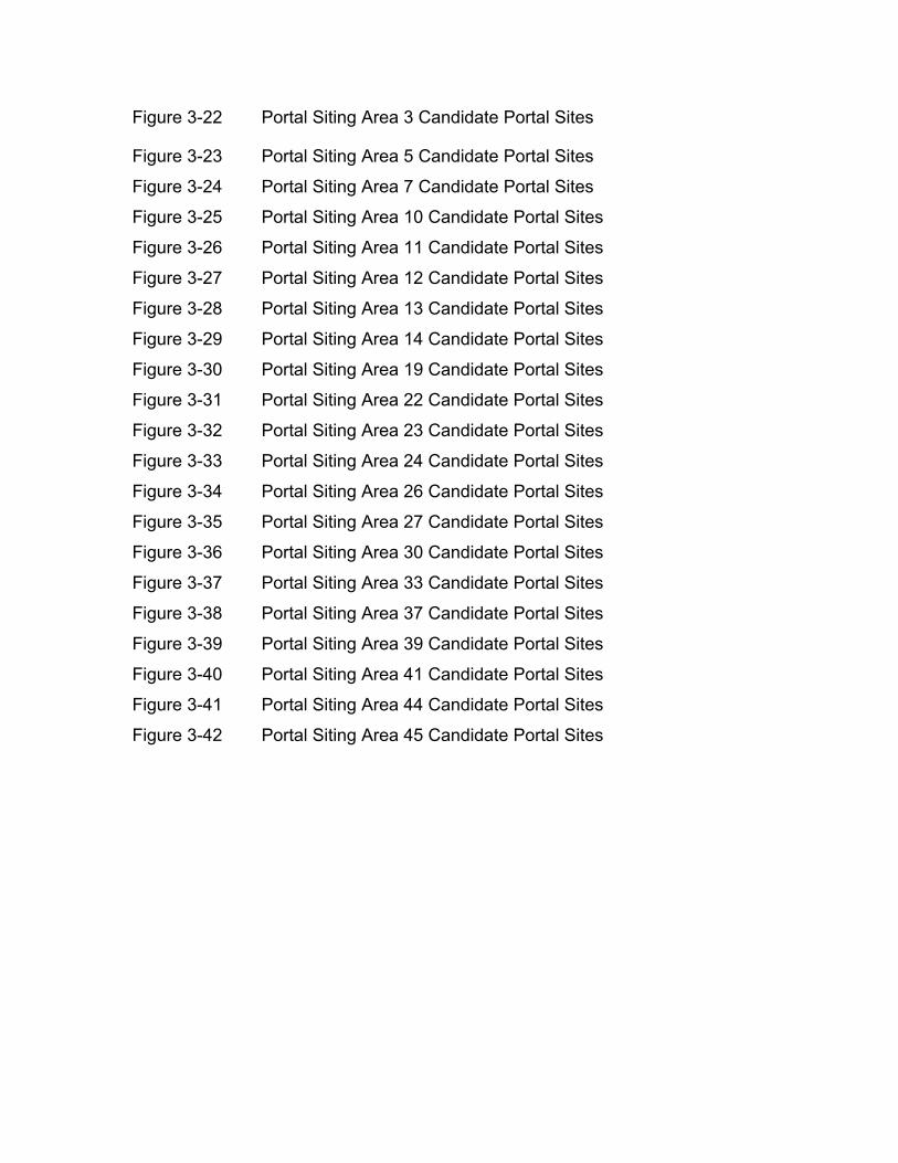
Figure 3-22 Portal Siting Area 3 Candidate Portal Sites
Figure 3-23 Portal Siting Area 5 Candidate Portal Sites
Figure 3-24 Portal Siting Area 7 Candidate Portal Sites
Figure 3-25 Portal Siting Area 10 Candidate Portal Sites
Figure 3-26 Portal Siting Area 11 Candidate Portal Sites
Figure 3-27 Portal Siting Area 12 Candidate Portal Sites
Figure 3-28 Portal Siting Area 13 Candidate Portal Sites
Figure 3-29 Portal Siting Area 14 Candidate Portal Sites
Figure 3-30 Portal Siting Area 19 Candidate Portal Sites
Figure 3-31 Portal Siting Area 22 Candidate Portal Sites
Figure 3-32 Portal Siting Area 23 Candidate Portal Sites
Figure 3-33 Portal Siting Area 24 Candidate Portal Sites
Figure 3-34 Portal Siting Area 26 Candidate Portal Sites
Figure 3-35 Portal Siting Area 27 Candidate Portal Sites
Figure 3-36 Portal Siting Area 30 Candidate Portal Sites
Figure 3-37 Portal Siting Area 33 Candidate Portal Sites
Figure 3-38 Portal Siting Area 37 Candidate Portal Sites
Figure 3-39 Portal Siting Area 39 Candidate Portal Sites
Figure 3-40 Portal Siting Area 41 Candidate Portal Sites
Figure 3-41 Portal Siting Area 44 Candidate Portal Sites
Figure 3-42 Portal Siting Area 45 Candidate Portal Sites

Figure 3-1
Typical Working PortalEquipment Layout
BRIGHTWATER FINAL EIS
Department ofNatural Resources and Parks
Wastewater TreatmentDivision
King County
File Name: 157689.P3.EP.33_W072003002SEA • CH 3_PROJECT DESCRIPTION • Fig 3-1_ Typical
Working Portal Equipment Layout • 9/17/03 • lw
Data Source: HDR Prepared by: CH2MHILL

Figure 3-2
Typical Retrieval PortalEquipment Layout
BRIGHTWATER FINAL EIS
Department ofNatural Resources and Parks
Wastewater TreatmentDivision
King County
File Name: 157689.P3.EP.33_W072003002SEA • CH 3_PROJECT DESCRIPTION • Fig 3-2_ Typical
Retrieval Portal Equipment Layout • 9/17/03 • lw
Data Source: HDR Prepared by: CH2MHILL

�������������� ��
���������
������������ ����������
���������
�����������
���������
����� !��"
�� � #���� !��"
�����������
�
���
���
���
�!����� ���
����
$�%&��'�(�)*�&���&+��,)��-�,&(./&�0,��������� ���!�����"��� �
#��$�% ����
�+�&�1��2
����(*)�'&��)(�(-+�.�.)(���,'&%�&,3��(-)'%�+�.*�)'&1&����4)*,)��-�,&(.�,,�35�-��)-�&(��2���)��()��-����(��)�(�4'&0�,()��%��,�(�&��)(,)�2&��&(���,6�7%��,,)��'%+��.6&,�)&--��&-46-)'%+���(�,,6��'�+�(�,,6)������,�)����,�)*,�-��(*)�'&��)(���(��)�(�4,�&++()�3�+�&3+�*)�&(4��(��&+6,%�-�&+6�(.���-�6�(-�.�(�&+6)�-)(,�8��(��&+.&'&��,�(-+�.�(�63��()�+�'���.�)6+),���1�(��,)�+),�%�)*��,��,�+��(�*�)'����,�)�'�,�,�)*����(*)�'&��)(-)(�&�(�.)(���,'&%��(4,&+�)*���,'&%)��(*)�'&��)()(���,'&%�,%�)��3���.�7-�%�342�����(%��'�,,�)()*��(��)�(�4�
&�'���!�(���9:���/��/���;�<9�<<�<<���=/� >��$����/�� �=������;�)����?�-�(��4#&%=�@��@<�=�'@''
)����*�+�(����#��

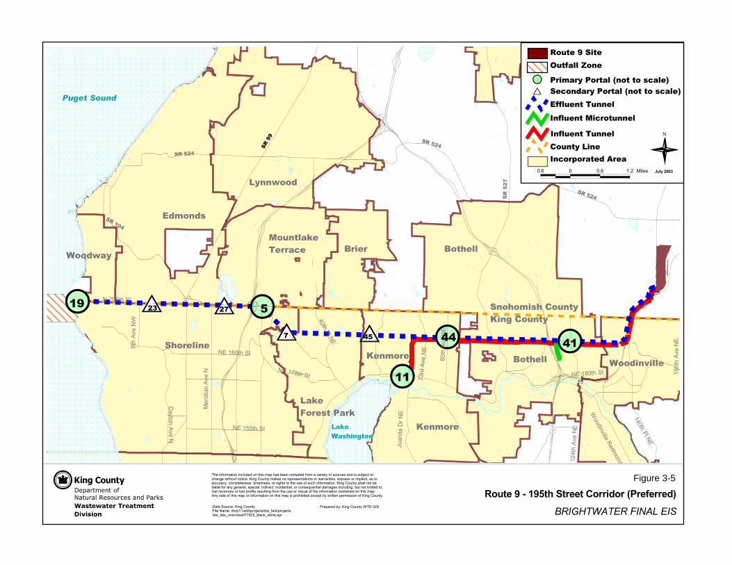
�������� �� ��
����
��
�����������
� �������� �
�������� ��
��������� �
������� �
�
������ ��
���������
����������
����������
������ ��
����������
���������� � �!���� �
���������
����������
���������� ��"����� ��
�������������� ��������
������
�����
�����
�
������
������
������
�� �
��
��
�� ��
� �� ��
��������
�������������� �! ""�# $"� " $��� ��
��� �%�" ���&�"�
���" $��� �� '�����(���
'������
���"
���" ���
�
)�#�"*�"�� ��+" ���������
,�-����.��
�--� ���!�� �
�� &"���"��&�"����/��������#�� 0�� � #����"��&�"����/��������#�� 0
��� ������
�#" � �#" �#� ��� $
)�-� ���!�� ��)�-� �����#"���� �
���������
�������������� ������ ���� �����������������������������
%�&� ��'�(� ���)�!��������*��� ��������$�!�+���$�, ��*�!+�� ��)�!������ ����)�$��* $������$�$�,- *����*���& �.�����������* #�/��&�0������!�1 $���� + $ �������$���.����� $2� 3+ $$����!+�� �2��$����**��*�2�*�!+� � � $$2���! ��� $$2����&��$������ ��$ ��)�$�*����)�!�����#�/��&�0������$���������, ����,� �)������& � ��2�$+ *���2����� *�2���*�� �����2���*��$ 4� ��������!�& $���*�����&2�,���������!�� ����2��$�� � �� $�����$��+�)��$� $�����&�)�!��� ��$ ���!�$� ��)��� ���)�!������*������ ��������$�!�+#����$�� ��)����$�!�+�����)�!������������$�!�+��$�+���,�� �� 3* +��,��.��� ��+ !�$$�����)�/��&�0�����#
��������* 5�/��&�0�����%�� ��! 5���+�566.��6+�- *�$6,.7) �$6+�- *�$6,.7) �$7�� �� .������7,��*17.��� #�+
� +� ��,�5�/��&�0�������(��89�
��� '����������
���������
Figure 3-5

����������������������� ��������������� ���������������
�������������� ���� ���������� �������������� ������������������������ ����!�����"#�$��%� $�����"&������������'�����������(��)�&&�(�* �$��"& �����+��+�����(,+--
�������������!%' ��������� !���!�.�!/00%�����-�&��"�1�����(�'� "��$� ��&2����3 "����#����������������������
$��%������!
��4

����������������������� ������������� ���������� ������ �
�������������� ���� ���������� �������������������������������������� ����!�����"#�$��%� $�����"&������������'�����������(��)&�(��&��*�&&�(���"��(������+��+�����(,+--
�������������!%' ��������� !���!�.�!)//%�����-�&��"�0�����(�'� "��$� ��&1����2 "�#��$������������������#���
%��&�'����!
���������������� �����������

����������������������� ������������� ���������� ������ �
�������������� ���� ���������� �������������� ������������������������ ����!�����"#�$��%� $�����"&������������'�����������(�����(��&��)�&&�(���"��(������*��*�����(+*,,
�������������!%' ��������� !���!�-�!.//%�����,�&��"�0�����(�'� "��$� ��&1����2 "�#��$������������������#���
%��&�'����!
���������������� �����������
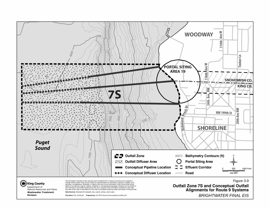
-70
0
-500
-40
0-100
-600
114t
h A
ve W
116t
h A
ve W
24th
Ave
NW
Tim
ber L
n20
th A
ve N
W
Rich
mon
dBe
ach
Dr
NW 199th St
SNOHOMISH CO.
KING CO.
WOODWAY
SHORELINE
PugetSound
���������� ���� �� ����
������ ������ ����
���� ��� �������
����
���������� ���� ��� ��� ���� ��� �����
���������� �������
� � � ��
��� ��������� �� ����� �� ���� �� ��� ���� ������ �� � ������ �� ��� �� ��� �� ����� � �� ����� ������� ���� �� ���� ������ ���� �� ������������� � ��������� ������ � ������� �� ��� �� �� ����������� ���������� � ����� �� ��� ��� �� �� � ���������� ���� ������ ����� ��� �������� �� ��� ������� ��� ���� ����� �� �� �������� � ������������ ������ �� ������� ��� ��� ������ ������� ������� � ���� ������ �������� �� ��� ��� � ����� �� ��� ��������� �������� �� ���� ��� �� ���� �� ���� �� � ��������� �� ���� �� �� ��������� �� ��� �� ������ �������� �� ���� �������
���� �� ����� !������ �� ��������" � ��� �� ��� ������ �� � �����
���� ����� #$%&'()'*���� ��� ���� !�� �� +,- .����� ����� ������ / +�� 0���
' *'' 1''' #���
�
" �� #$$%
PORTAL SITINGAREA 19
& ����� '���
& ����� ���� ��� ����
���� � �� �� ����� (�������
���� � �� ���� ��� (�������
BRIGHTWATER FINAL EIS
Figure 3-9& ����� '��� )� ��� ���� � �� & �����
���������� ��� �� �� * �������
7S
��������������� ������ ��� �������������� ��
���������������� �������������������������� ������������������������� ��������������� ���� ������������������ ������������������������������������������������������������������������ �� ��� ����������������������������������������������� ��������������������������������������������������������������� ���������� ����� ������������ ���������������������� ������������������������������������������������������������������������������������������������� �������������������� ��������������������������������������������������������� ��������������������������������������
�� ����
��
������������
��!�������"�#
$
%������� ���#
&'(��
� ���#$
"������ ���#
)*��� ���#
$
+,�� ���#$
(*���-��#$
#$�&+)���.�
&(*���-��#$
)��� ���#/
#$�&00���.�
/�����������1������1�
#�'*0���.�
#$�&)0���.�
#$�&)*���.� &02��
� ���#$
�������������� ��������
������
�����
�����
�
������
������
������
��
�� ��
��
��
��
��
��
�� �� ��
��������
������������� !�"!##�$! %#�!# %���!��
�� !�&�#!���'�#
!���#! %���!�� (�����)���!
(������
!���#!
���#!���!
���������
�� !(����������
�
*�$�#+�#��!��,#!���������!
-�.����/��!
�..�!���"��!�
�� '#���#��'�#����0��������$��!1�� �!$����#��'�#����0��������$��!1
���!������!
*�2 * *�2 &�' %����
*�.�!���"��!��*�.�!�����$#����!�
-��������3�������������/�"�45."����.�� �3������������6����#��3����&377���7���� ��7��8����7���� ��7��8����8�������*+&0*,8��� �8��������
6�����,92
��������
Figure 3-10

���������������������� ������������� ���������� ������ �
�������������� ���� ���������� ��������������������������������������� ����!�����"#�$��%� $�����"&������������'�����������(��)&�(��&��*�&&�(���"��(�����+��+�����(,+--
�������������!%' ��������� !���!�.�!)//%�����-�&��"�0�����(�'� "��$� ��&1����2 "�#��$������������������#���
%��&�'����!
���������������� �����
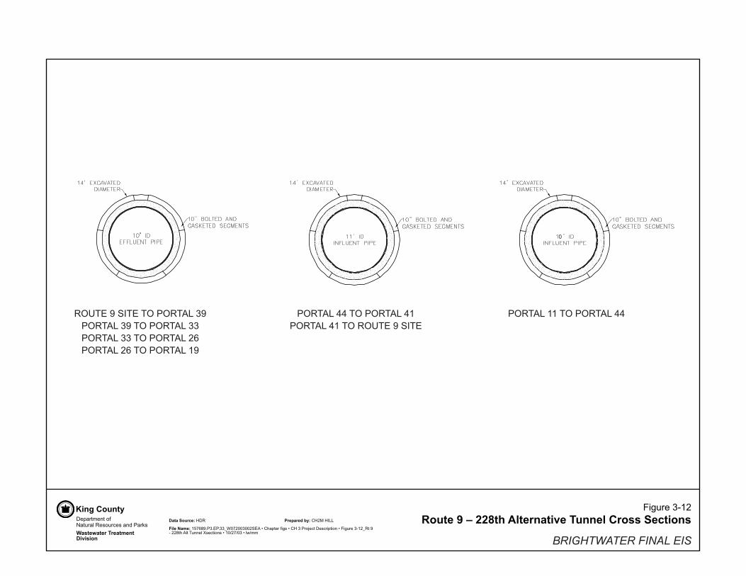
����������������������� ��������������� ���������������
�������������� ���� ��������� ��������������� ������������������������ ����!�����"#�$��%� $�����"&�������������'�����������(��)�&&�(�* �$��"& ����+� +�����(,+--
�������������!%' ��������� !���!�.�!/00%�����-�&��"�1�����(�'� "��$� ��&2����3 "����#����������������������
$��%������!
�
�4')�0�55�)4��4')�0�5�4')�0�5�)4�'46)�����/)�
'46)�����/)��)4��4')�0����4')�0����)4��4')�0����4')�0����)4��4')�0����4')�0����)4��4')�0��
�4')�0��)4��4')�0�55

����������������������� ������������� ���������� ������ �
�������������� ���� ���������� ��������������������������������������� ����!�����"#�$��%� $�����"&�������������'�����������(�����(��&��)�&&�(���"��(�����*��*�����(+*,,
�������������!%' ��������� !���!�-�!.//%�����,�&��"�0�����(�'� "��$� ��&1����2 "�#��$������������������#���
%��&�'����!
���������������� �����
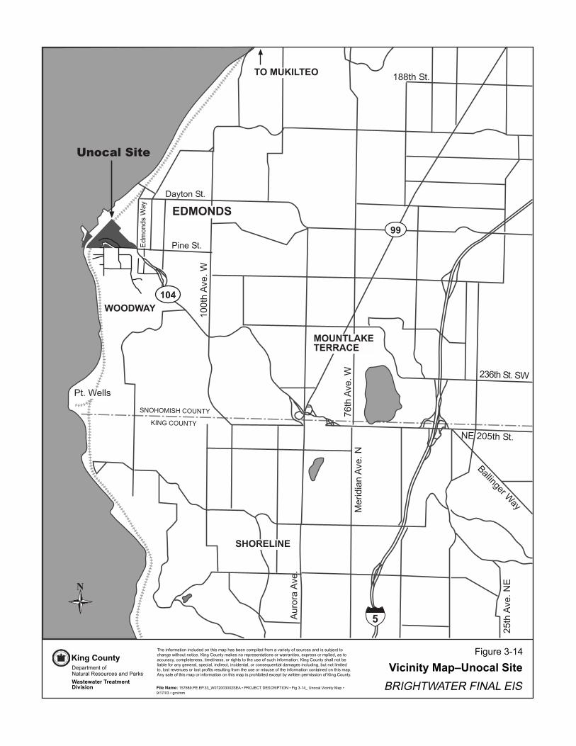
�������������� ��
����������
������������� �������
����������
���������������
����� �����!
"#$%�&�'�
���(���&�'
)*
( )+�
�!
,� ��$'
-�!$( �$'
�..$%�$'
����)�� �&�'�
/0$%�&�'�
�11$%�&�'�
,$'����+
"�0$%�$'��
���������
�"1#$%�$'
�������
�������
����������������
���������
�����������
��
!"
#
�%�� 2(�*�$�( � 3��)�)( $%�+*�4%�+5�� 3(*4���)2�(*�&����$!(2+(��3�+� )�++�56�3$$(3%� ��7�$%(�$ ($�3�'�� ��(� $!*�8�+ (��4��+� $�$�( +(�7���� $��+9�:4��++(�*4���)9�+$(�33���3!93(*4��$� �++9$�*��� �++9(����%$+$($%��+�(2+�3%� 2(�*�$�( '�� ��(� $!+%��� ($5����5��2(�� !�� ����9+4�3���9� )���3$9� 3�)� $��9(�3( +�;�� $���)�*���+� 3��)� �95�$ ($��*�$�)$(9�(+$��&� ��+(��(+$4�(2�$+��+��$� �2�(*$%��+�(�*�+�+�(2$%�� 2(�*�$�( 3( $�� �)( $%�+*�4'� !+���(2$%�+*�4(�� 2(�*�$�( ( $%�+*�4�+4�(%�5�$�)�:3�4$5!7��$$� 4��*�++�( (2�� ��(� $!'
$�����%�&��#/0.<',','��=�1/"11�11"��>,��?��-����,����>�������=� (3��@�3� �$!��4><A�/A1�>�*A**
-�4��$*� $(2��$������+(��3�+� ),��8+�'��(��)��)��%�����*�'� �
���+�� ,���

Department ofNatural Resources and ParksWastewater TreatmentDivision
King County
Influent PumpStation (IPS)
Headworks
UV Disinfection for Reuse
BNSF RR
Admira
l Way
Anaerobic DigestersAdministrationBuilding
CITY OF EDMONDS
Stormwater TreatmentFacility (Wet Pond)
Solids Handling Building
Port of Edmonds Marina
Realigned Pine Street
Maintenance Building
UV Disinfection for Puget SoundDischarge for Main Stream
Chemical Disinfection forPuget Sound Discharge forSplit Stream
MBR Tanks
Reuse Pump Station
Existing 42" Lower Willow Creek Discharge Pipe
Existing 72" Storm Sewer Outfall
Secondary Odor Control
Aeration Basins
Fine Screens
Effluent Pump Station
115kV Electrical SubstationMBR Support Building
Secondary Clarifiers(Only for CAS)
IPS Odor Control
Aerated Grit
Ballasted Sedimentation
Conventional PrimaryClarifiers
Primary & HeadworksOdor Control
Solids Odor Control
15kV Electrical Substation
Cogeneration
Chemical Building
Willow Creek
Proposed Lower Willow CreekDischarge to Puget Sound(Open Channel)
Stormwater Dischargeto Outfall
Effluent Dischargeto Outfall
Pine Street
SR
-104
(Edm
onds
Way
)
Odor Control forTruck Staging
Piping and Equipment Galleries
Relocated Existing72" Storm Sewer
36 mgd Treatment Plant Facilities
Additional Facilities forExpansion to 54 mgd
Wetlands
3000
Feet
200100
Potential Additional Facilitiesfor 54 mgd CAS and Class ABiosolids
Retaining Walls
Property Boundary
The information included on this map has been compiled from a variety of sources and is subject tochange without notice. King County makes no representations or warranties, express or implied, as toaccuracy, completeness, timeliness, or rights to the use of such information. King County shall not beliable for any general, special, indirect, incidental, or consequential damages including, but not limited to,lost revenues or lost profits resulting from the use or misuse of the information contained on this map.Any sale of this map or information on this map is prohibited except by written permission of King County.
Data Sources: King County Wastewater Treatment Division
File Name: 157689.P3.EP.33_W072003002SEA • PROJECT DESCRIPTION • Fig 3-15_ Unocal 36 and 54 mgd Plant • 9/17/03 • dk/mm BRIGHTWATER FINAL EIS
Figure 3-15
Prepared by: CH2MHILL
Shelleberger Cre
ek
GalleryGallery
Gal
lery
Conceptual Layout for a 36 and 54 mgdPlant at the Unocal Site
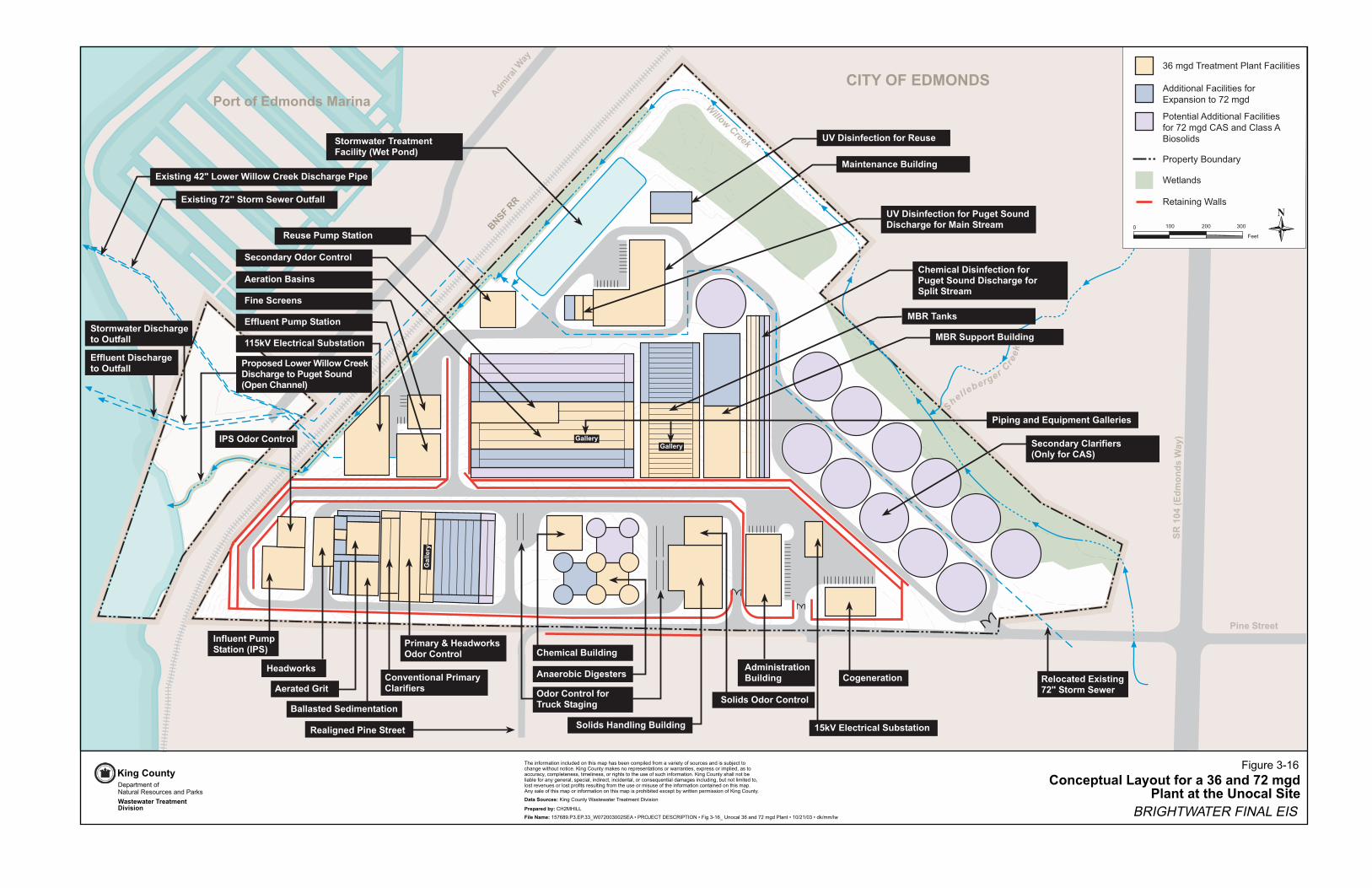
�������������� ������ ������������������������������� � � ��
� ���������
�������������������
� ! ��"#$%������������������������������������
���������� ��!������" ��
#�����������"��� ���$#�"%
&������'�
!(�� � ����� �������)����
*+",�))
-� �������
-�����. ��� �������-� � ����� ��*� �� ��
�#/�0,�1�20+�"
"����������������,�� � ���$��������%
"�� ���&���� ���*� �� ��
��������1������2�� ��
)��� ������ ���"�����
2� ���������*� �� ��
� � ����� � ����� ������������"������ �� ��������"�� ��"����
2*)���'�
)���������"��� ��
13 �� ���4�5�������� ���������'�� �� ������ ��
13 �� �����5�"����"�����0������
"���������0�����������
-���� ���*�� ��
, ���"������
1������������"��� ��
667'(�1����� ����"�.���� ��2*)�"�������*� �� ��
"������������� � ���$0���������-"%
#�"�0�����������
-�������8� �
*���������"�� ����� ��
������� ������� ������� � ���
�� ����9�&������'�0�����������
"�� ���0�����������
67'(�1����� ����"�.���� ��
��������� ��
� � ����*� �� ��
���������
���������������� ���������'� �� ��������������"����$0����� �����%
"���������� �� �������0������
1��������� �� �������0������
� ���"�����
")�6:4�$1���������%
0������������������'�"��� ��
� � �������1;� �����8����� ��
)���������13 �� ����5�"����"����
!(�� � ����� �������������"����� �� ���������2� ��"���� "&&&
����
'&&$&&
������(� ����(
��������
���� � �!�����
��� � ������ � � �����)���� ��*'�!�
"%�!������������������ � � ��
����� ����� � ������ � � ����*'�!�+�����+������ �� ��
�,� ������ � ��� �����, ����,��-������ �������.�� ��(�� ������� �� -/�����,��!�0 �, ��� ��12 �!+ ��(����������������� ���0������ ��3�)������ ��� ��3������ ���(3�����������3� ��� ����3�� !,����,� ���� �, ������ �12 �!+ ��(�,�����-�� �-������(!������3���� ��3 �� ����3 �� ������3�����4 ��� ������!�� ��� � �!3- ���� � ����3�����.�� ��������� ����� �� �!����,� ���� � ����,� ������ ����� �����, ����1��(������, ����� ������ ���, ���� ���, - ����)����-(0� �������� �� ��2 �!+ ��(1
�����"������<�2 �!+ ��(�����0�������������� . � �
, ���+��<�$5*%671�"1��1""8�&*'&&"&&'���9��:;�+����+�����:�9� !"#$%8<����"%���*'�!������9$&='$=&"9��=��=�0
���������.�<�+�'>����
�
���
���
��
8������8������
8������

�������������� ������ ������������������������������� � � ��
� ���������
�������
�� �������
������� �!����"�����#� ������!�� �� �
��������
" ���������
��$%&'�( ���������)
����
����
������
�������� �����
� ����������
��������
!�������������� �����!�����!��"��������������#�������� ���������� "$�����!��%�&��! ������'(��%) ������������������������&���������*�+�������������*������ ����*�����������*����������*���%!����!� ���� �!���������'(��%) ����!�����"����"�������%������*�������*��������*����������*�����, ����������%������ ���%*" �����������*�����#�� ��������������� ����%����!� ������ ����!��������������������!�����'-��������!�����������������!���������!�"�����+����"�&����������������(��%) ���'
���������*��+�(��%) ��������&���� ����������#����
� ������+��./012'��'3�'��4��/�������53-6��783) �35)�9� 97�6��%�:�/4� ����������62;��;��6��;�� ��9<= �- 3��9�-�395
��% ���:�/
"��,�����-�+�)=��=9��
(.������)(.������)
�
���
���
��
���� ��������������-�����
����������-����� 3��#���
����-�����
� � �������
�����=����%�����
����!�&��!���5���7�����
3+����%����� ������
���������������
� ����������%3�������
� ����������%3+��
�����3�������
�����3+��
5!��: ���*��%: ���*���3������������%>.1�������?
���*�,�����/������#�����01���"������ �2�!��� �����/ ������2��3��*���� ��
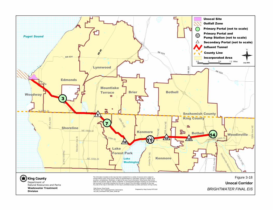
������������������������� ��
���������������� �������������������������� ������������������������� ��������������� ���� ������������������ ������������������������������������������������������������������������ �� ��� ����������������������������������������������� ��������������������������������������������������������������� ���������� ����� ������������ ���������������������� ������������������������������������������������������������������������������������������������� �������������������� ��������������������������������������������������������� ��������������������������������������
!�����"#$$
%��������&�������������'�(�)*+(����+�� �&������������!����,��&����$&--���-���� ��-��.����-���� ��-��.����.�������/0$1/".��� �.��������
��
��
��
�� �� ����
��2�������(�,
3
4������� ���,
$56��
� ���,3
(������ ���,
7/��� ���,
3
0"�� ���,3
6/���%��,3
,3�$07���+�
$6/���%��,3
7��� ���,'
,3�$11���+�
'�����������8������8�
,�5/1���+�
,3�$71���+�
,3�$7/���+� $19��
� ���,3
�������������� ��������
������
�����
�����
�
������
������
������
����
�
�
���� ��
�
��������
�������������� �! ""�# $"� " $��� ��
��� �%�" ���&�"�
���" $��� �� '�����(���
'������
���"
���" ���
����
�
�
���� ��
�
�
)�#�"*�"�� ��+" ���������
,�-����.��
�� &"���"��&�"�������&�*���������/��������#�� 0
�� � #����"��&�"����/��������#�� 0
1��#������
/�9 / /�9 $�5 4����
)�-� ���!�� ��
� �������
&"���"��&�"����/��������#�� 0�����������
��� '����������
Figure 3-18

���������������������� ��������������������
�������������� ������������ ��������������� ������������������������ ����!�����"#�$��%� $�����"&�������������'&"$�(�(���&���)��*&�(��&��+�&&�(���"��(�����,��,�����(-,..
�����������!%/ ������������!�0�!*11%�����.�&��"�2�����(�/� "��$� ��&3����4 �������������� �����
��!�"����
���������������� �����
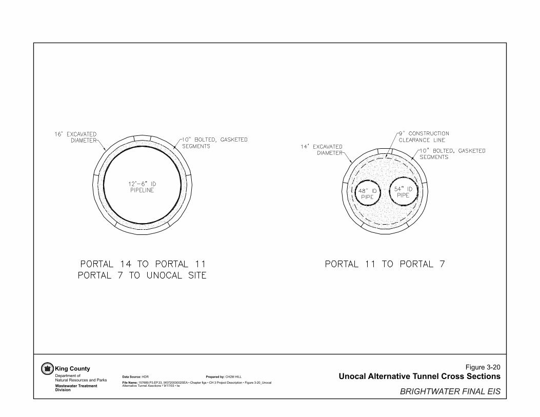
Figure 3-20
Unocal Alternative Tunnel Cross Sections
BRIGHTWATER FINAL EIS
File Name: 157689.P3.EP.33_W072003002SEA • Chapter figs • CH 3 Project Description • Figure 3-20_UnocalAlternative Tunnel Xsections • 9/17/03 • lw
Data Source: HDR Prepared by: CH2M HILLDepartment ofNatural Resources and Parks
Wastewater TreatmentDivision
King County

UNOCALSITE
104-600
-500
-400
-300
-100
-200
EDMONDS
WOODWAY
N
PugetSound
6
BRIGHTWATER FINAL EIS
Outfall Zone 6 and Conceptual OutfallAlignment for Unocal System
Figure 3-21
Outfall Zone
Outfall Diffuser Area
Preferred Pipeline Location
Preferred Diffuser Location
Bathymetry Contours (ft)
Unocal Site
Influent Corridor
Road
Department ofNatural Resources and Parks
Wastewater Treatment
Division
The information included on this map has been compiled from a variety of sources and is subject to change without notice. King County makes no representations or warranties, express or implied, as to accuracy, completeness, timeliness, or rights to the use of such information. King County shall not be liable for any general, special, indirect, incidental, or consequential damages including, but not limited to, lost revenues or lost profits resulting from the use or misuse of the information contained on this map. Any sale of this map or information on this map is prohibited except by written permission of King County.
Data Sources: Standard KC datasets: kcsn, parcel, wtrbdy, wtrcrs used.
File Name: FIG_03-21 Prepared by: KC WLR Visual Communications & Web Unit
0 500 1000 Feet
July 2003
Chi
nook
Rd
Noo
tka
Rd
Bella Coola Rd Mak
ah R
d
Pine St
Unoco Rd
Admira
l Way
Dayton St

����������
����
�����
��������
���
��
���
� � ���
��
���
�������
����������
��
����
��
�
�
�
�
�
�
��� � ��� ��� ��� ��� ����
�������������� �������������
������������ ����������
������ ����������������������������������������������������������������������������������������������������������������������� ���!�������"�����������������������������������#��$����������������#�������������#�������������#�����������#����������������������������������������� ���!�������������������������������������#��������#���������#������������#���������%���������������������#������������������#���������������������������������������������������������������������������������������������������&��������������������������������������������������������������$������������������������������ ���!�����
���������� ������������������ �!"�#���������� �������"������ $������%�������
����������&''(
�����������������
��������������)����(���������������������
!���������'������(���������!������)���'������(�����&���
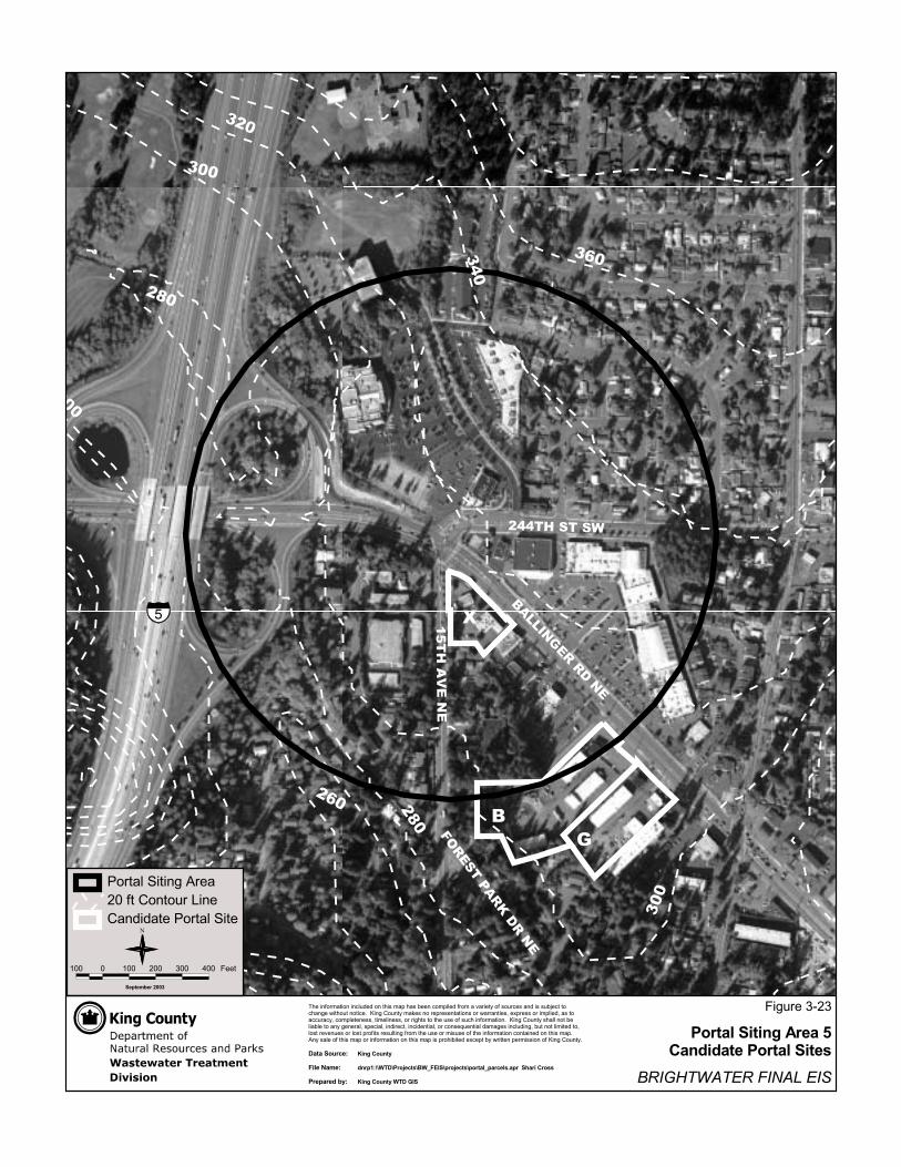
��������������
�� �����������������������
���
���
���
���
���
���
��� ���
���
���� ������
������ �
��
�
��� � ��� ��� ��� ��� ����
�������������� �������������
������������ ����������
������ ����������������������������������������������������������������������������������������������������������������������� ���!�������"�����������������������������������#��$����������������#�������������#�������������#�����������#����������������������������������������� ���!�������������������������������������#��������#���������#������������#���������%���������������������#������������������#���������������������������������������������������������������������������������������������������&��������������������������������������������������������������$������������������������������ ���!�����
���������� ������������������ �!"�#���������� �������"������ $������%�������
����������&''(
�����������������
��������������)����*���������������������
!���������'������(���������!������)���'������(�����&���

��������������� ��������
����
���
���
���
���
���
���
���
�
��� � ��� ��� ��� ��� ����
�
�������������� �������������
������������ ����������
������ ����������������������������������������������������������������������������������������������������������������������� ���!�������"�����������������������������������#��$����������������#�������������#�������������#�����������#����������������������������������������� ���!�������������������������������������#��������#���������#������������#���������%���������������������#������������������#���������������������������������������������������������������������������������������������������&��������������������������������������������������������������$������������������������������ ���!�����
���������� ������������������ �!"�#���������� �������"������ $������%�������
����������&''(
�����������������
��������������)����*���������������������
!���������'������(���������!������)���'������(�����&���

��������������
��� ��
������
��� �������
������� ��������������������
����
��
������ ���
������
�
�
� �
��� � ��� ��� ��� ��� ����
�����������������
����������������� ����������������������
��������������
�
���������� ��� ���������������� �!�"#�����������������!�������$������%���������
���� �������������������������������������� ������������ ������������������������������������������� �������!�������������������������������"�#��������������"������������"������������"����������"��������������� ����� ������������� ��������������������������������"�������"��������"�����������"�������$�����������������������"���������������"��������������������� ������������ ����������������� ���� ��������������������������%������� ���������� ����������������������������#������������������������ ���� ������
�������&�'
�������&���� '����&�(
'����&�(�����)#�����������(�
��������(�����)����� � ������*���(�����)�����%���

�����������
���������� �
����
� ��
���
�� �
�� ���
���
��
��
��
��
��
������
���
����������������������
�����������
�
��� � ��� ��� ��� ��� ����
�
�������������� �������������
������������ ����������
������ �������������������������������������������������������������������������������������������������������������������� ��!���"�������#�����������������������������������$��%����������������$�������������$�������������$�����������$�������������������������������������� ��!���"�������������������������������������$��������$���������$������������$���������&���������������������$������������������$�������������������������������������������������������������������������������������������������� '��������������������������������������������������������������%������������������������������!���"����
���������� ������������������ �!"�#���������� �������"������ $������%�������
����������&''(
��������������)���������������������������
�����������������
"���������(������)���������"������*���(������)�����'���
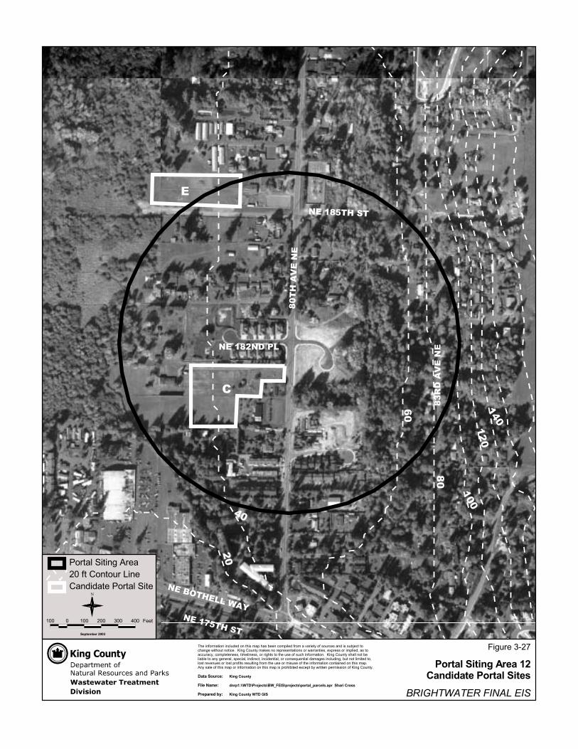
����
����
���
�����������
����
����
���
�����������
��
��
��
�����
������
�����������
������������
�
�
��� � ��� ��� ��� ��� ����
�������������� �������������
������������ ����������
������ �������������������������������������������������������������������������������������������������������������������� ��!���"�������#�����������������������������������$��%����������������$�������������$�������������$�����������$�������������������������������������� ��!���"�������������������������������������$��������$���������$������������$���������&���������������������$������������������$�������������������������������������������������������������������������������������������������� '��������������������������������������������������������������%������������������������������!���"����
���������� ������������������ �!"�#���������� �������"������ $������%�������
����������&''(
��������������)�����&���������������������
�����������������
"���������(������)���������"������*���(������)�����'���
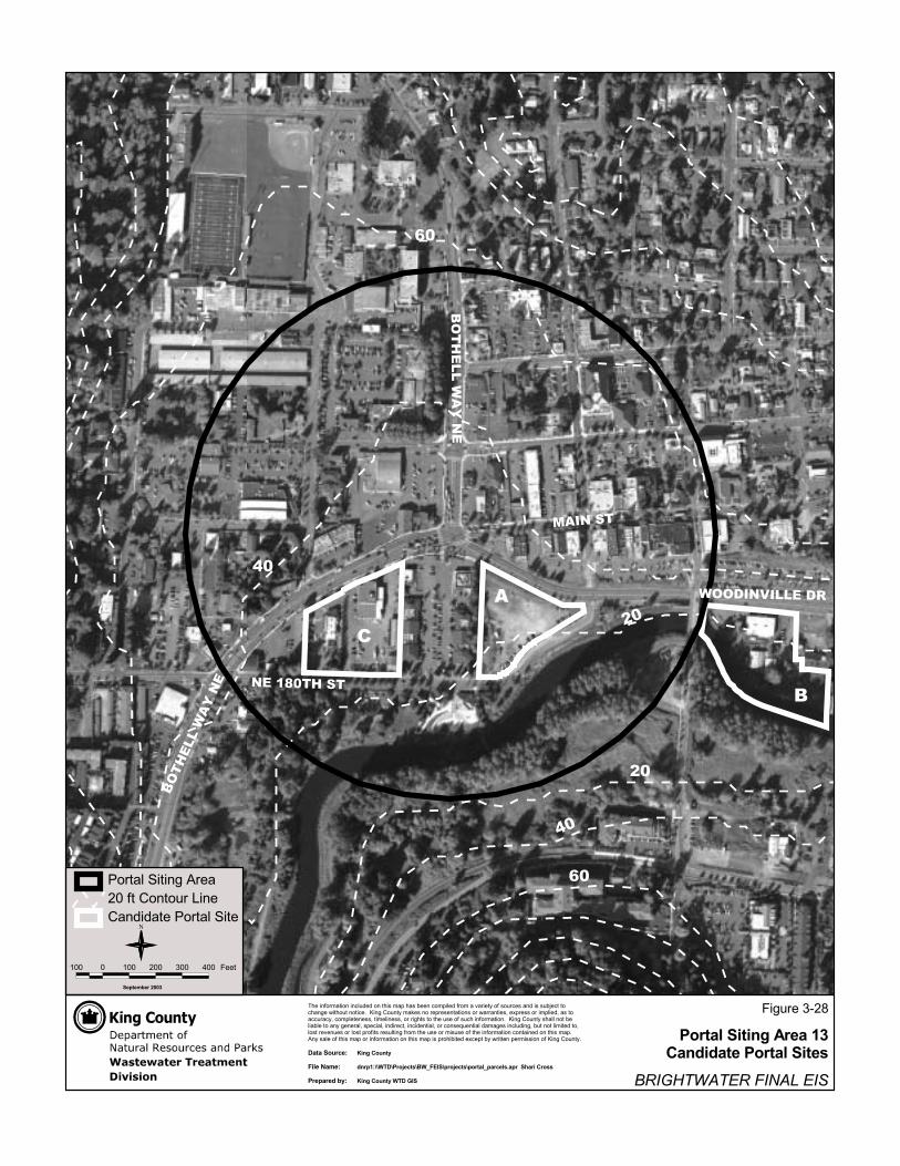
�����������
�����
� �����������
� �������
����
��
��
��
��
��
�
�
� �������������
��� � ��� ��� ��� ��� ����
�
�������������� �������������
������������ ����������
������ �������������������������������������������������������������������������������������������������������������������� ��!���"�������#�����������������������������������$��%����������������$�������������$�������������$�����������$�������������������������������������� ��!���"�������������������������������������$��������$���������$������������$���������&���������������������$������������������$�������������������������������������������������������������������������������������������������� '��������������������������������������������������������������%������������������������������!���"����
���������� ������������������ �!"�#���������� �������"������ $������%�������
����������&''(
��������������)�����(���������������������
�����������������
"���������(������)���������"������*���(������)�����'���

��������������
������� �� ����
��������
���
�������
����
�����
���
�
��
������� �� ��
������
�
�������������� �������������
������������ ����������
�������� ���������������������������������������������������������������������������������������������������� !���"�������#�������������������������������$�%��������������$������������$������������$����������$��������������������������������� !���"���������������������������������$�������$��������$�����������$�������&�����������������������$���������������$�������������������������������������������������������������������������������������� '��������������������������������������������������%�������������������������!���"�����
���������� ������������������ �!"�#���������� �������"������ $������%�������
����������&''(
��������������)�����*���������������������
�����������������
(�� � (�� ��� �� ��� ����
"��������)�����*�������"������+���)�����*�����'���

����
����
��
����
���
���
���
���
��� ��������
� ��
����
���
� �
���
���
���
��������
��
���������
�����������
�
�
�
��� � ��� ��� ��� ��� ����
�
�������������� �������������
������������ ����������
������ ����������������������������������������������������������������������������������������������������������������������� ���!�������"�����������������������������������#��$����������������#�������������#�������������#�����������#����������������������������������������� ���!�������������������������������������#��������#���������#������������#���������%���������������������#������������������#���������������������������������������������������������������������������������������������������&��������������������������������������������������������������$������������������������������ ���!�����
���������� ������������������ �!"�#���������� �������"������ $������%�������
����������&''(
��������������)�����*���������������������
�����������������
!���������'������(���������!������)���'������(�����&���

�����������
����
�� �
�����
�� �
�������
���
��������
���
���
���
���
���
���
���
���
������
������
���
�
�
�
��� � ��� ��� ��� ��� ����
�
�������������� �������������
������������ ����������
������ ����������������������������������������������������������������������������������������������������������������������� ���!�������"�����������������������������������#��$����������������#�������������#�������������#�����������#����������������������������������������� ���!�������������������������������������#��������#���������#������������#���������%���������������������#������������������#���������������������������������������������������������������������������������������������������&��������������������������������������������������������������$������������������������������ ���!�����
���������� ������������������ �!"�#���������� �������"������ $������%�������
����������&''(
��������������)����&&���������������������
�����������������
!���������'������(���������!������)���'������(�����&���
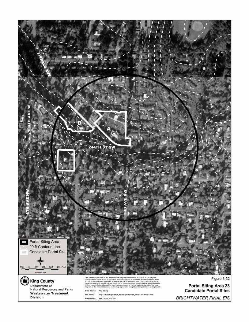
�����������
����
�� �
�����
�� �
�������
���
��������
���
���
�
��� � ��� ��� ��� ��� ����
�
�������������� �������������
������������ ����������
������ ����������������������������������������������������������������������������������������������������������������������� ���!�������"�����������������������������������#��$����������������#�������������#�������������#�����������#����������������������������������������� ���!�������������������������������������#��������#���������#������������#���������%���������������������#������������������#���������������������������������������������������������������������������������������������������&��������������������������������������������������������������$������������������������������ ���!�����
���������� ������������������ �!"�#���������� �������"������ $������%�������
����������&''(
��������������)����&(���������������������
�����������������
!���������'������(���������!������)���'������(�����&���
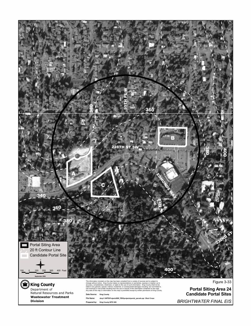
����������
����
�����
���
�����
���������
��� ���
���
���
���
���
��� ���
��
�
�
��� � ��� ��� ��� ��� ����
�������������� �������������
������������ ����������
������ ����������������������������������������������������������������������������������������������������������������������� ���!�������"�����������������������������������#��$����������������#�������������#�������������#�����������#����������������������������������������� ���!�������������������������������������#��������#���������#������������#���������%���������������������#������������������#���������������������������������������������������������������������������������������������������&��������������������������������������������������������������$������������������������������ ���!�����
���������� ������������������ �!"�#���������� �������"������ $������%�������
����������&''(
�����������������
��������������)����&*���������������������
!���������'������(���������!������)���'������(�����&���

�����������
����
����� �������
���
���
���
��� ��� ���
������
�����
�
�
���
�
��� � ��� ��� ��� ��� ����
�������������� �������������
������������ ����������
������ ����������������������������������������������������������������������������������������������������������������������� ���!�������"�����������������������������������#��$����������������#�������������#�������������#�����������#����������������������������������������� ���!�������������������������������������#��������#���������#������������#���������%���������������������#������������������#���������������������������������������������������������������������������������������������������&��������������������������������������������������������������$������������������������������ ���!�����
���������� ������������������ �!"�#���������� �������"������ $������%�������
����������&''(
�����������������
��������������)����&*���������������������
!���������'������(���������!������)���'������(�����&���

����������
����
���� ��
��
����
�� ����
��
��
���
���
������
���
���
���
�
�
��� � ��� ��� ��� ��� ����
�
�������������� �������������
������������ ����������
������ �������������������������������������������������������������������������������������������������������������������� ��!���"�������#�����������������������������������$��%����������������$�������������$�������������$�����������$�������������������������������������� ��!���"�������������������������������������$��������$���������$������������$���������&���������������������$������������������$�������������������������������������������������������������������������������������������������� '��������������������������������������������������������������%������������������������������!���"����
���������� ������������������ �!"�#���������� �������"������ $������%�������
����������&''(
�����������������
��������������)����&*���������������������
"���������(������)���������"������*���(������)�����'���

�����������
����
��
��
����
��
���� ��������
���
���
���
���
���
�
�
�����������
�
��� � ��� ��� ��� ��� ����
�������������� �������������
������������ ����������
������ �������������������������������������������������������������������������������������������������������������������� ��!���"�������#�����������������������������������$��%����������������$�������������$�������������$�����������$�������������������������������������� ��!���"�������������������������������������$��������$���������$������������$���������&���������������������$������������������$�������������������������������������������������������������������������������������������������� '��������������������������������������������������������������%������������������������������!���"����
���������� ������������������ �!"�#���������� �������"������ $������%�������
����������&''(
�����������������
��������������)����('���������������������
"���������(������)���������"������*���(������)�����'���

������������������
���
����
��
���
��
��
�
��
�
�
�
�
��� � ��� ��� ��� ��� ����
�������������� �������������
������������ ����������
������ �������������������������������������������������������������������������������������������������������������������� ��!���"�������#�����������������������������������$��%����������������$�������������$�������������$�����������$�������������������������������������� ��!���"�������������������������������������$��������$���������$������������$���������&���������������������$������������������$�������������������������������������������������������������������������������������������������� '��������������������������������������������������������������%������������������������������!���"����
���������� ������������������ �!"�#���������� �������"������ $������%�������
����������&''(
�����������������
��������������)����((���������������������
"���������(������)���������"������*���(������)�����'���

������
����
����������
�����
����
�������
����
��
� � ��
��
��
��
�
�
�
�
��� � ��� ��� ��� ��� ����
�������������� �������������
������������ ����������
������ �������������������������������������������������������������������������������������������������������������������� ��!���"�������#�����������������������������������$��%����������������$�������������$�������������$�����������$�������������������������������������� ��!���"�������������������������������������$��������$���������$������������$���������&���������������������$������������������$�������������������������������������������������������������������������������������������������� '��������������������������������������������������������������%������������������������������!���"����
���������� ������������������ �!"�#���������� �������"������ $������%�������
����������&''(
�����������������
��������������)����(*���������������������
"���������(������)���������"������*���(������)�����'���

����
����
���
���������
���
����
�����
���
����
���
���
�
��
���
���
���
��
���
���
���
�
�
�
�
��� � ��� ��� ��� ��� ����
�������������� �������������
������������ ����������
������ �������������������������������������������������������������������������������������������������������������������� ��!���"�������#�����������������������������������$��%����������������$�������������$�������������$�����������$�������������������������������������� ��!���"�������������������������������������$��������$���������$������������$���������&���������������������$������������������$�������������������������������������������������������������������������������������������������� '��������������������������������������������������������������%������������������������������!���"����
���������� ������������������ �!"�#���������� �������"������ $������%�������
����������&''(
�����������������
��������������)����(*���������������������
"���������(������)���������"������*���(������)�����'���

��������
���
���������
��� �����������
����������������
�
��
����
�����
������
������
����
�����
������
��������������
������
� �����
���������
�����
��
����������
�
�
�
�
�
�
�������� ��������������������� ��� ������������������ �� �������������� ����������������� ������������������������������ ��������������� �������� �� �������� ����������������� ��� ���� ���������������������������������������������������������� ������������������ ����������� ������ �������� �������� ���������������������� ���������!����� ��� � ����������������������������������������������������������������������������������������������� ������� ������������� ��"���� ���������� �������� ������������ ���������������� �������������������������������������� �������������������
������������������
#�� � #�� ��� $�� %���
� ���� ���&�� ��'���#����������(���&�� ��'������"��
����������
�
%������)*��
����������������� ���������� ������������� �!"�
#����$�%�� �����&&�� &�'��� &��(#)"�&�'��� &����(����� (��*�+�����,����
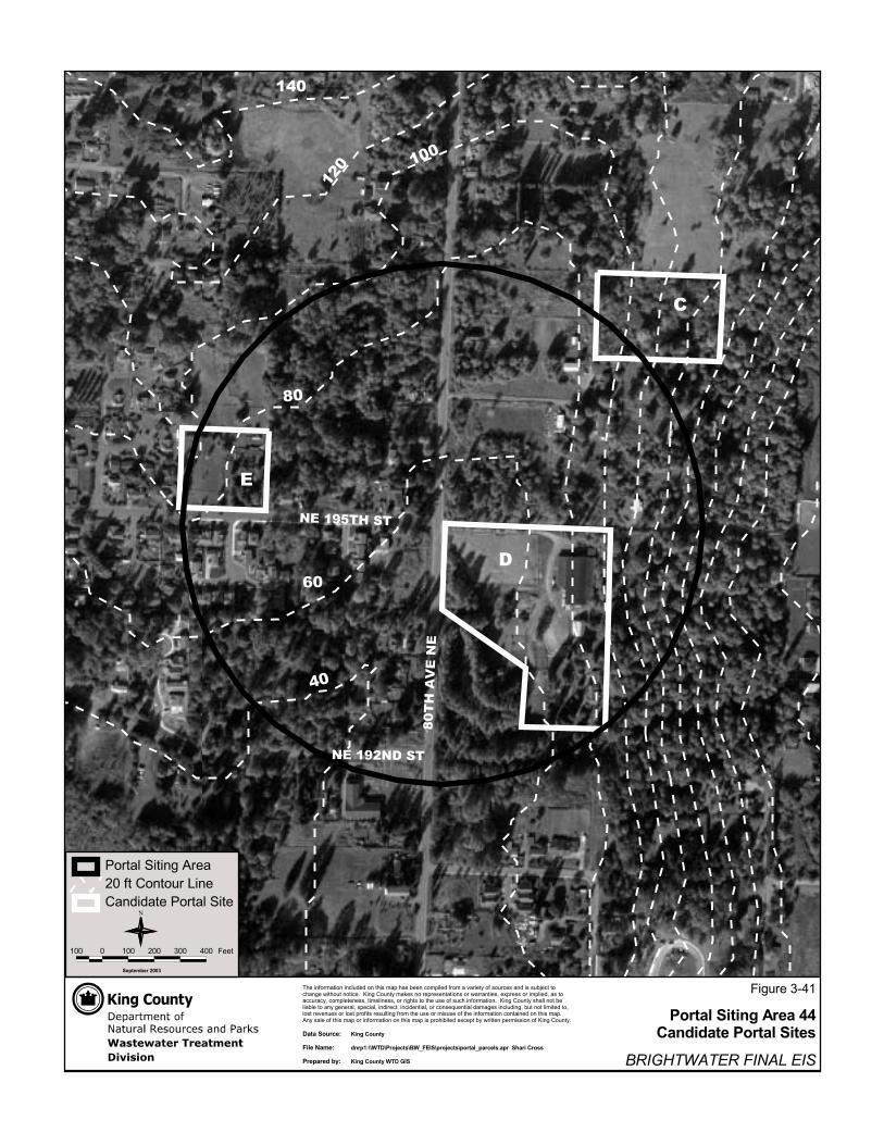
����
����
���
���������
��� �����
��
��
��
�
��
��
�
�
�
��� � ��� ��� ��� ��� ����
�
�������������� �������������
������������ ����������
������ ����������������������������������������������������������������������������������������������������������������������� ���!�������"�����������������������������������#��$����������������#�������������#�������������#�����������#����������������������������������������� ���!�������������������������������������#��������#���������#������������#���������%���������������������#������������������#���������������������������������������������������������������������������������������������������&��������������������������������������������������������������$������������������������������ ���!�����
���������� ������������������ �!"�#���������� �������"������ $������%�������
����������&''(
�����������������
��������������)����**���������������������
!���������'������(���������!������)���'������(�����&���

����
����
���
���������
����� ����
�������
����
��
��
�
��
��
��
��
�
��
� �
�
��� � ��� ��� ��� ��� ����
�
�������������� �������������
������������ ����������
������ ����������������������������������������������������������������������������������������������������������������������� ���!�������"�����������������������������������#��$����������������#�������������#�������������#�����������#����������������������������������������� ���!�������������������������������������#��������#���������#������������#���������%���������������������#������������������#���������������������������������������������������������������������������������������������������&��������������������������������������������������������������$������������������������������ ���!�����
���������� ������������������ �!"�#���������� �������"������ $������%�������
����������&''(
�����������������
��������������)����*+���������������������
!���������'������(���������!������)���'������(�����&���