Chapter 3: Artificial Lighting - new-learn.info · SynthLight Artificial lighting About This is...
66
SynthLight Handbook Chapter 3: Artificial Lighting Authors: Wilfried Pohl, Andreas Zimmermann Revision: 6 November 2003
Transcript of Chapter 3: Artificial Lighting - new-learn.info · SynthLight Artificial lighting About This is...

SynthLight Handbook Chapter 3: Artificial Lighting Authors: Wilfried Pohl, Andreas Zimmermann Revision: 6 November 2003
SynthLight Artificial lighting
About This is chapter 3 of 5 of the handbook for the SynthLight on-line course on lighting: 1. Fundamentals 2. Daylight 3. Artificial Lighting 4. Integrating Artificial Light and Daylight 5. Case Studies For more material and the other chapters, please visit the SynthLight web site at: http://www.learn.londonmet.ac.uk/packages/synthlight/index.html. This site also has an on-line test consisting of 15 questions each for each of the four main chapters. If you answer more than 80% of questions correctly, you will be sent a Certificate of Virtual Attendance. Acknowledgements SynthLight was part-funded by the European Commission under the SAVE programme. The project number is 4.1031/Z/01-123/2001. Disclaimer Although much care has been taken in ensuring that all facts and concepts laid out in this document are correct, the author can not be held liable for any mistakes that might have crept in. If you discover any inconsistencies, please notify < [email protected] >, so future revisions of this document can be corrected.
1
SynthLight Artificial lighting
Table of contents 3.1 INTRODUCTION 3 3.2 LIGHT SOURCES 3 3.2.1 INCADESCENT LAMPS 3
3.2.2 DISCHARGE LAMPS 7
3.2.2.1 Fluorescent lamps 7
3.2.2.2 Compact Fluorescent lamps 11
3.2.2.3 High density discharge lamps 12
3.2.2.4 Lamp overview 14
3.2.3 USE OF LED TECHNOLOGY FOR LIGHTING 15
3.2.3.1 Basics 15
3.2.3.2 Optical performance 16
3.2.3.3 Life time 19
3.2.3.4 Power supply, circuitry 19
3.2.3.5 Measurement 19
3.3 LUMINAIRES 20 3.3.1 INTODUCTION 20
3.3.2 PHOTOMETRIC REQUIREMENTS 20
3.3.2.1 Luminous intensity distribution 21
3.3.2.2 Luminous flux distribution 23
3.3.2.3 Luminaire efficiency 24
3.3.2.4 Luminance distribution 25
3.3.3 TECHNICAL REQUIREMENTS 26
3.3.4 MATERIALS USED FOR THE REDIRECTION OF LIGHT 29
3.3.4.1 Types of reflection 33
3.3.5 DESIGN OF A LUMINAIRE 35
3.4 LIGHTING DESIGN 41 3.4.1 PROJECT ANALYSIS 41
3.4.1.1 Qualitative objectives 42
3.4.1.2 Quantitative objectives 43
3.4.2 DEVELOPING THE LIGHTING CONCEPT 43
3.4.3 DESIGN DEVELOPMENT 44
3.4.4 CONTRACT DOCUMENTS 44
3.4.5 CONSTRUCTION AND EXCECUTION 45
3.4.6 POSTOCCUPANCY EVALUATION 45
3.5 IMPORTANT DESIGN CRITERIAS 46
3.5.1 ILLUMINANCE LEVELS 46
3.5.1.1 Maintenance rate 48
3.5.2 BALANCED LUMINANCES 48
2
SynthLight Artificial lighting
3.5.3 LIMITATION OF GLARE 51
3.5.3.1 Direct glare 52
3.5.3.2 Reflected glare 55
3.5.4 DIRECTION OF LIGHT AND SHADOWS 57
3.5.5 COLOUR OF LIGHT 59
3.5.5.1 Color of light 59
3.5.5.2 Color of surfaces 60
3.5.5.3 Color rendering 60
3.6 COST 62 3.6.1 INITIAL COST 62
3.6.2 MAINTENANCE COST 63
3.6.3 ENERGY COST 63 3.7 REFERENCES 64
3.7.1 PUBLICATIONS 64
3.7.2 CATALOGUES 64
3.7.3 JOURNALS 64
3.7.4 WEB SITES FOR LED 64
3
SynthLight Artificial lighting
3.1 INTRODUCTION Although today there is a huge number of different light sources these sources work either on the principle of thermal excitation or luminescence on one hand, discharge sources on the other hand. A century ago there were only incandescent lamps. This technological pursuit is intensified during the last years in an effort to produce light sources with higher luminous efficacies, better color rendering properties and longer life expectancies. Of course factors like purchase cost and maintanance cost are by no means quite essential for the proper choice. Luminous efficacies were increased enormously through the centuries from 0.01 lm/W candle to above 100 lm/W for modern “white” light sources. Torch was probably the first lighting source and fixture as well around 400000 years BC followed by simple lamps made of shell and fat around 13000 BC and pottery lamps (with refined design) around 600 BC. Candle was appeared around 400 AD and was the first light source that could be used either in interior or exterior with or without a transparent protective case. Around 1800 the carbon arc lamps were introduced followed by gas lamps in 1814. Today’s similar incandescent lamp has appeared during 1879 by Thomas Edison with luminous efficacy ~1.4 lm/W. High Intensity Discharge lamps introduced in 1901, low pressure sodium in 1932, fluorescent in 1932 while quartz and metal halide in 1960. It should be mentioned here another innovative light source, the sulfur lamp. It operation is rather simple and can be realized by exciting sulfur and quartz with microwaves with similar properties to sunlight but without the ultraviolet component. The lamp itself may last indefinitely, and the microwave generator may need occasional replacement parts. Lumen depreciation is negligible, and CRI will remain fairly constant. In recent years LED use have become widwspread. There are two possible approaches to produce white light. The first is to use a blue LED coated with a white phosphor (1996). This technology has the disadvantage of short life cycle (~6 years). The second method of producing white light is to use additive mixing of the three primary colours red, green and blue. 3.2 LIGHT SOURCES 3.2.1 Incandescent lamps The incandescent lamp is of simple construction - a hot wire (the filament) centred in the glass bulb. An electric current that passes through the wire heats it to incandescence. Thus, the wire emits radiation respectively light. The length and the diameter of the wire determine the amount of electrical current consumed by the lamp. This regulates its light output.
4
SynthLight Artificial lighting
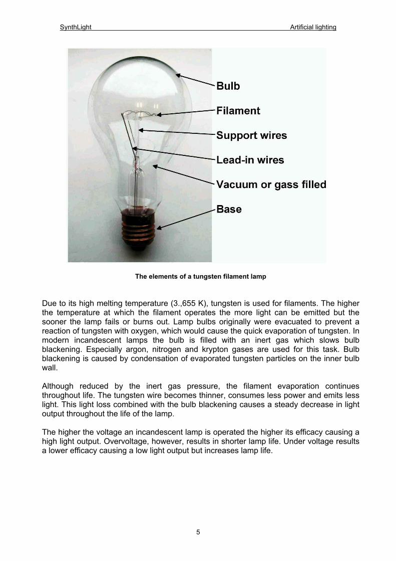
The elements of a tungsten filament lamp Due to its high melting temperature (3.,655 K), tungsten is used for filaments. The higher the temperature at which the filament operates the more light can be emitted but the sooner the lamp fails or burns out. Lamp bulbs originally were evacuated to prevent a reaction of tungsten with oxygen, which would cause the quick evaporation of tungsten. In modern incandescent lamps the bulb is filled with an inert gas which slows bulb blackening. Especially argon, nitrogen and krypton gases are used for this task. Bulb blackening is caused by condensation of evaporated tungsten particles on the inner bulb wall. Although reduced by the inert gas pressure, the filament evaporation continues throughout life. The tungsten wire becomes thinner, consumes less power and emits less light. This light loss combined with the bulb blackening causes a steady decrease in light output throughout the life of the lamp. The higher the voltage an incandescent lamp is operated the higher its efficacy causing a high light output. Overvoltage, however, results in shorter lamp life. Under voltage results a lower efficacy causing a low light output but increases lamp life.
5

SynthLight Artificial lighting
6
Lamp life versus light flux As regards energy-saving lamp life is very important. By mean average life we mean the span of time which 50% of all incandescent lamps work under normal operating conditions. Reducing wattage can prolong the chart lamp life, causing, however, a reduction in efficacy and light output. This is how extended service incandescent lamps achieve their long life (2500 h). Their lumen output is approximately 15 % less than standard 750-hr and 1000-hr life lamps. Although these lamps are more expensive than standard ones, their longer life is advantageous in locations that are difficult to relamp. Luminous efficacy can be improved by using a coiled coil filament and by filling the glass bulb with halogen gas. This measure ensures that the evaporated tungsten atoms redeposit themselves on the filament in a closed cycle. The main advantages of a halogen lamp are a higher luminous efficacy of up to 25 lm/W, a longer life of approx. 2,000 h, a white colour and constant light flux throughout its life. Low voltage lamps: The wattage of an incandescent filament lamp is defined as the product of the voltage delivered at the socket multiplied by the amperes flowing through the filament. To achieve certain wattage of a filament lamp using low voltage a high current is necessary. This high current requires large diameters of the filament to carry it. A filament with a large diameter can be operated at higher temperatures, which increases efficacy. Furthermore
SynthLight Artificial lighting
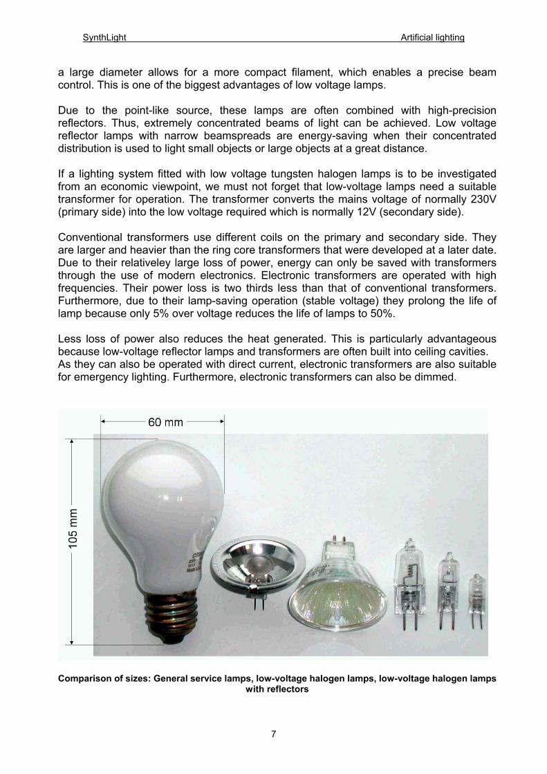
a large diameter allows for a more compact filament, which enables a precise beam control. This is one of the biggest advantages of low voltage lamps. Due to the point-like source, these lamps are often combined with high-precision reflectors. Thus, extremely concentrated beams of light can be achieved. Low voltage reflector lamps with narrow beamspreads are energy-saving when their concentrated distribution is used to light small objects or large objects at a great distance. If a lighting system fitted with low voltage tungsten halogen lamps is to be investigated from an economic viewpoint, we must not forget that low-voltage lamps need a suitable transformer for operation. The transformer converts the mains voltage of normally 230V (primary side) into the low voltage required which is normally 12V (secondary side). Conventional transformers use different coils on the primary and secondary side. They are larger and heavier than the ring core transformers that were developed at a later date. Due to their relativeley large loss of power, energy can only be saved with transformers through the use of modern electronics. Electronic transformers are operated with high frequencies. Their power loss is two thirds less than that of conventional transformers. Furthermore, due to their lamp-saving operation (stable voltage) they prolong the life of lamp because only 5% over voltage reduces the life of lamps to 50%. Less loss of power also reduces the heat generated. This is particularly advantageous because low-voltage reflector lamps and transformers are often built into ceiling cavities. As they can also be operated with direct current, electronic transformers are also suitable for emergency lighting. Furthermore, electronic transformers can also be dimmed.
Comparison of sizes: General service lamps, low-voltage halogen lamps, low-voltage halogen lamps
with reflectors
7
SynthLight Artificial lighting
GeneralService lamp
clearmatt
E27E40 25...1000 230...3200
5000...19000 ---- 9...1617...19 ww/1 1000
ReflectorlampPAR
insidemirrored E27 25...300 ---- 180...40000 ---- ww/1 2000
High voltageTungsten
Halogen lamp
clearmatt
R7sE27E14
60...200040...250
840...44000580...4200 ---- 14...22
14...17 ww/1 2000
Low voltageTungsten
Halogen lamp
ReflectorAl or glass
Gy 6,35G4 5...150 50...3200 ---- 10...21 ww/1 2000
Low voltageTungsten
Halogen lampwith reflector
clear matt
Gu 5,3Gy 4 10...250 ---- 600...45000 ---- ww/1 2000...4000
Life
h
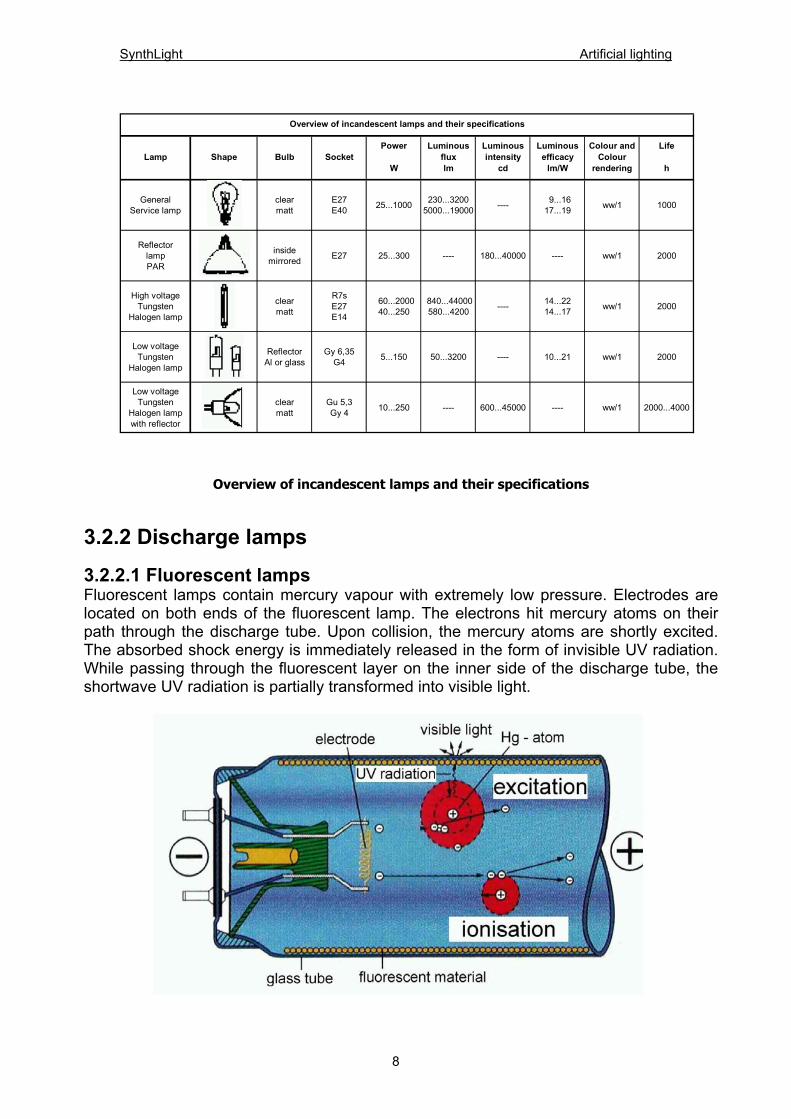
Overview of incandescent lamps and their specifications
Lamp Shape Bulb SocketPower
W
Luminousfluxlm
Luminousintensity
cd
Luminousefficacy
lm/W
Colour andColour
rendering
Overview of incandescent lamps and their specifications
3.2.2 Discharge lamps 3.2.2.1 Fluorescent lamps Fluorescent lamps contain mercury vapour with extremely low pressure. Electrodes are located on both ends of the fluorescent lamp. The electrons hit mercury atoms on their path through the discharge tube. Upon collision, the mercury atoms are shortly excited. The absorbed shock energy is immediately released in the form of invisible UV radiation. While passing through the fluorescent layer on the inner side of the discharge tube, the shortwave UV radiation is partially transformed into visible light.
8
SynthLight Artificial lighting
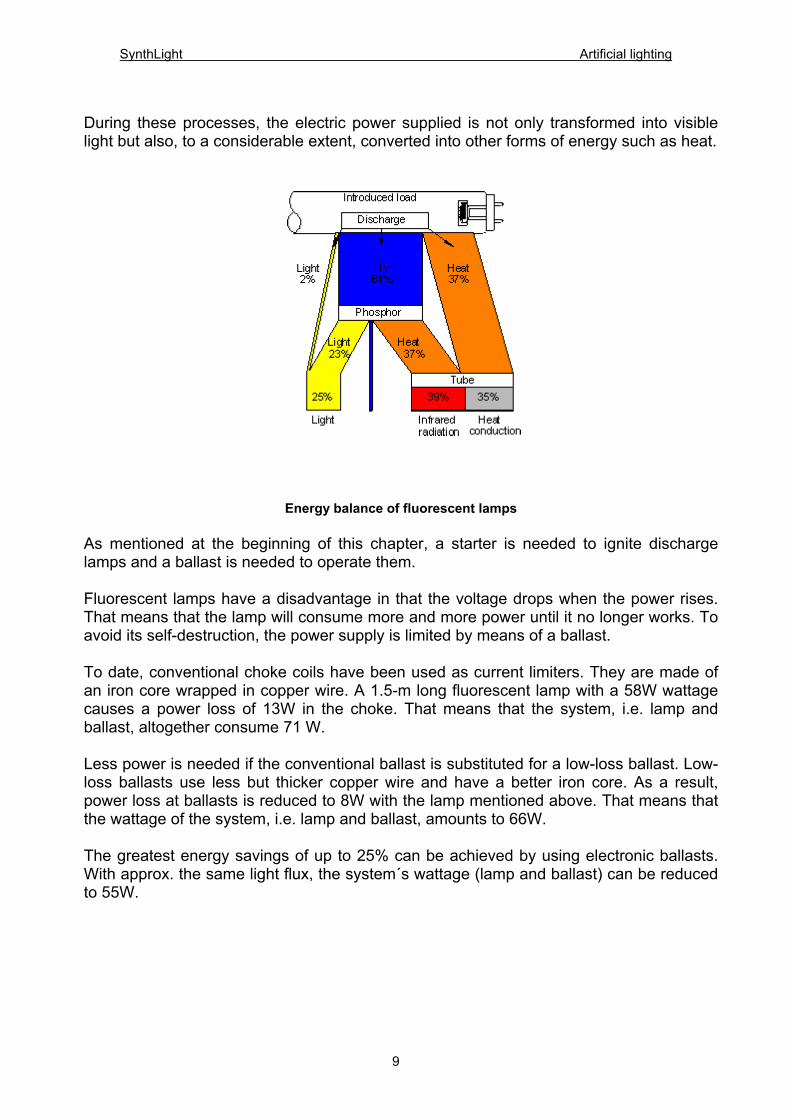
During these processes, the electric power supplied is not only transformed into visible light but also, to a considerable extent, converted into other forms of energy such as heat.
Energy balance of fluorescent lamps
As mentioned at the beginning of this chapter, a starter is needed to ignite discharge lamps and a ballast is needed to operate them. Fluorescent lamps have a disadvantage in that the voltage drops when the power rises. That means that the lamp will consume more and more power until it no longer works. To avoid its self-destruction, the power supply is limited by means of a ballast. To date, conventional choke coils have been used as current limiters. They are made of an iron core wrapped in copper wire. A 1.5-m long fluorescent lamp with a 58W wattage causes a power loss of 13W in the choke. That means that the system, i.e. lamp and ballast, altogether consume 71 W. Less power is needed if the conventional ballast is substituted for a low-loss ballast. Low-loss ballasts use less but thicker copper wire and have a better iron core. As a result, power loss at ballasts is reduced to 8W with the lamp mentioned above. That means that the wattage of the system, i.e. lamp and ballast, amounts to 66W. The greatest energy savings of up to 25% can be achieved by using electronic ballasts. With approx. the same light flux, the system´s wattage (lamp and ballast) can be reduced to 55W.
9

SynthLight Artificial lighting
While conventional and low-loss ballasts operate at a frequency of 50 Hz, electronic ballasts operate at a frequency of between 25,000 and 40,000 Hz. As the luminous efficacy of fluorescent lamps increases with increasing frequency, either a higher light flux is achieved with the same power loss as at 50 Hz (e.g. 58W), or approx. the same light flux as at 50Hz is produced with less power being consumed by the lamp.
Luminous efficacy of fluorescent lamps operated with electronic ballasts at various frequencies
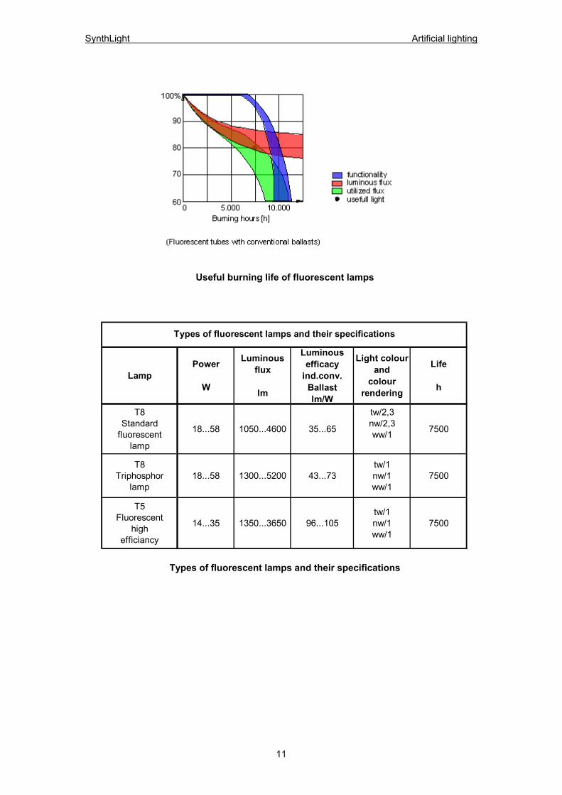
Lamp life of fluorescent lamps: To indicate the life of fluorescent lamps, their useful life is defined. It is the time required until the system’s light flux is reduced to 80% of its initial value (new value). The system’s decrease in light flux can, however, be traced back to the following: - a decrease in light flux due to burning period of lamp (fatigue of fluorescent material) - lamp failure - dirt accumulation The useful life of a lamp strongly depends on its operation. Fluorescent lamps operated with conventional ballasts last approx. 7,500 hours, those operated with electronic ballasts last from approx. 25,000 to 50,000 hours.
10
SynthLight Artificial lighting
11
Useful burning life of fluorescent lamps
LampPower
W
Luminousflux
lm
Luminousefficacy
ind.conv.Ballastlm/W
Light colourand
colourrendering
Life
h
T8Standard
fluorescentlamp
18...58 1050...4600 35...65
tw/2,3nw/2,3ww/1 7500
T8Triphosphor
lamp18...58 1300...5200 43...73
tw/1nw/1ww/1
7500
T5Fluorescent
highefficiancy
14...35 1350...3650 96...105tw/1nw/1ww/1
7500
Types of fluorescent lamps and their specifications
Types of fluorescent lamps and their specifications

SynthLight Artificial lighting
3.2.2.2 Compact fluorescent lamps a) CFL with built-in ballasts The major disadvantages of incandescent lamps are their low luminous efficacy of approx. 12 lm/W and their relatively short life (1000-2000 hr). The advantage they have, however, is their size. Depending on how fluorescent lamps generate light, lamps have been developed which already include the necessary ballast and, analogous to general service lamps, have their own lamp base. Although these lamps cannot be dimmed, due to the higher luminous efficacy of approx. 50 lm/W and their 8-fold life of approx. 8,000 hours, they are the ideal substitute for incandescent lamps, from an energy-saving viewpoint. That is why these lamps are also known as energy-saving lamps. Analogous to fluorescent lamps, they can be equipped with conventional (inductive) or electronic ballasts. With the latter, these lamps have a higher luminous efficacy, guarantee an immediate, flicker-free start and weigh less. Due to the low consumption of power required to achieve approximately the same light flux and the long life of these lamps, both energy and maintenance costs (lamp replacement) are saved. Due to the diversity of glass bulbs, these lamps are mainly used to replace tungsten lamps in restaurants, salesrooms, homes and rooms with decorative lighting. b) CFL with external ballasts Compact fluorescent lamps with external ballasts generate light according to the principle of fluorescent lamps. These lamps have thin, parallel fluorescent tubes, a built-in starter and a base. The lamps generate a light similar to that of tungsten lamps, have a high luminous efficacy and a life of 8,000 hours. The ballasts for their operation must be incorporated into the luminaire. The lamps’ low weight, small size, high luminous efficacy and long life are the main advantages of this lamp. They are normally applied in homes, restaurants and places, where economical lighting is desired. Lamps that are both compact and powerful are used in special fittings for the direct and/or indirect illumination of offices.
Compactfluorescent
lampsSocket
Power
W
Luminousflux
lm
Luminousefficacy incl.
Ballasts
lm/W
Colourand
colourrendering
Averagelife
h
Startingtime
min.
E27 9...25 375...1200 41...48 ww/1 5000 2E27 7...32 400...2000 58...63 ww/1 8000 1
G23 5...11 250...900 28...60 ww/1 8000 1
2 G 7 5...26 250...1800 42...50 ww/1 8000 1
G R 10q 16...28 1050...2050 50...57 ww/1 8000 1
2 G 11 18...55 1200...4800 40...79EVG
nw/1ww/1
8000(10000
with EVG)1
Various compact fluorescent lamps
withexternalballast
with built-inballast
Various compact fluorescent lamps
12
SynthLight Artificial lighting
3.2.2.3 High intensity discharge lamps (HID) The term high-intensity discharge applies to arc-discharge sources with a high power density. With most HID lamps, the arc tube is enclosed in an outer glass bulb. As with fluorescent lamps, HID lamps require ballasts to regulate the arc current flow and to deliver the proper voltage to strike the arc. Electronic ballasts are more efficient and provide more precise control of the arc tube voltage over life, resulting in more consistent colour and longer life. Before the lamp will relight, it must cool sufficiently to reduce the vapour pressure to a point where the arc will restrike. The time required to cool depends on a luminaire´s ability to dissipate heat. Typically in a luminaire, HID lamps will relight in 3 to 10 minutes. HID lamps used for illumination in buildings belong to three principal families: 1) mercury-vapour lamps 2) high-pressure sodium lamps 3) low pressure sodium lamps 4) metal-halide lamps 1) Mercury-vapour lamps With mercury vapour lamps, light is produced by an electric discharge through mercury vapour, resulting in poor quality of a greenish hue. The addition of phosphor coatings on the inside of the bulb improves colour rendering because phosphor complements the red part of the spectrum. 2) High-pressure sodium lamps High-pressure sodium lamps are manufactured with tube-shaped ellipsoidal bulbs with wattage of between 50 W and 1000 W. The discharge space is a transparent ceramic burner, which is resistant to the aggressivity of sodium. High-pressure sodium lamps achieve a extremely high luminous efficacy up to 130 lm/W, however, they radiate a yellowish colour of light and achieve bad colour rendering. Thus, these lamps are only used in warehouses and similar locations when used in interiors; their main application is outdoors for the illumination of streets and car parks. 3) Low-pressure sodium lamps
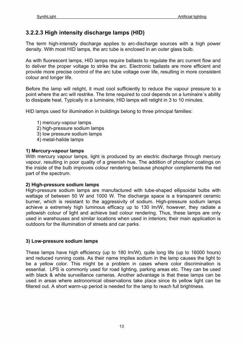
These lamps have high efficiency (up to 180 lm/W), quite long life (up to 16000 hours) and reduced running costs. As their name implies sodium in the lamp causes the light to be a yellow color. This might be a problem in cases where color discrimination is essential. LPS is commonly used for road lighting, parking areas etc. They can be used with black & white surveillance cameras. Another advantage is that these lamps can be used in areas where astronomical observations take place since its yellow light can be filtered out. A short warm-up period is needed for the lamp to reach full brightness.
13
SynthLight Artificial lighting
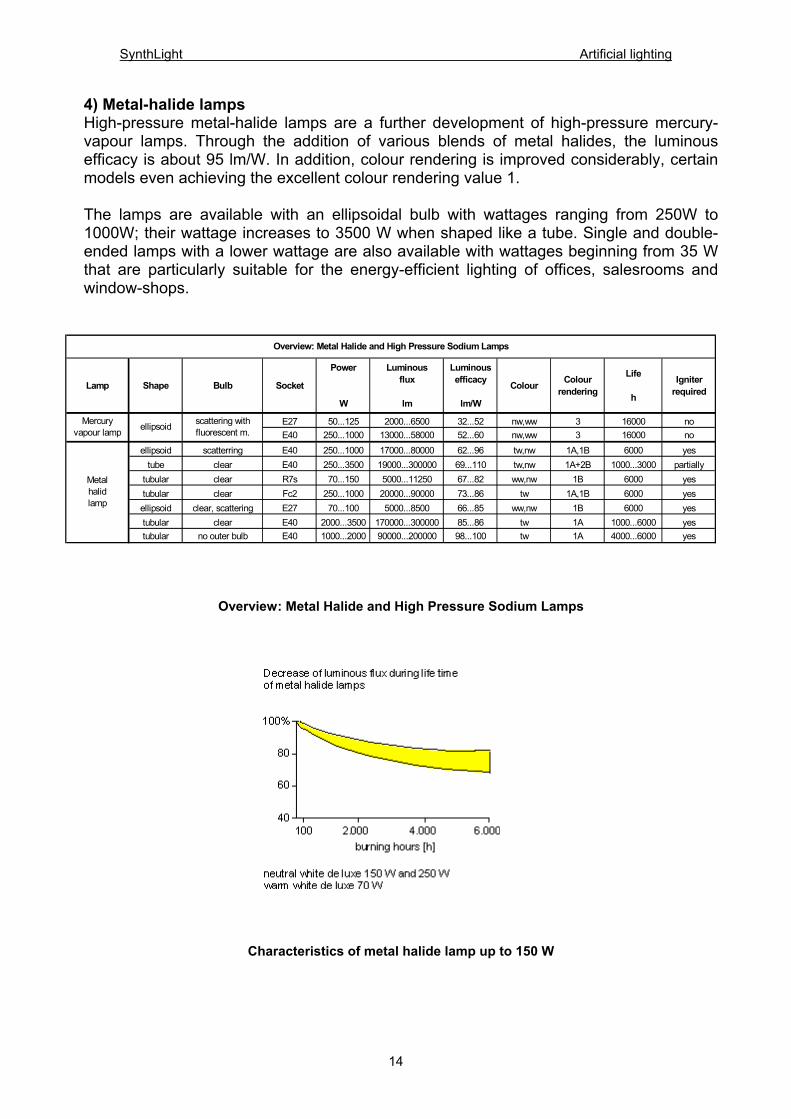
4) Metal-halide lamps High-pressure metal-halide lamps are a further development of high-pressure mercury-vapour lamps. Through the addition of various blends of metal halides, the luminous efficacy is about 95 lm/W. In addition, colour rendering is improved considerably, certain models even achieving the excellent colour rendering value 1. The lamps are available with an ellipsoidal bulb with wattages ranging from 250W to 1000W; their wattage increases to 3500 W when shaped like a tube. Single and double-ended lamps with a lower wattage are also available with wattages beginning from 35 W that are particularly suitable for the energy-efficient lighting of offices, salesrooms and window-shops.
Lamp Shape Bulb Socket
Power
W
Luminousflux
lm
Luminousefficacy
lm/W
Colour Colourrendering
Life
h
Igniterrequired
E27 50...125 2000...6500 32...52 nw,ww 3 16000 noE40 250...1000 13000...58000 52...60 nw,ww 3 16000 no
ellipsoid scatterring E40 250...1000 17000...80000 62...96 tw,nw 1A,1B 6000 yestube clear E40 250...3500 19000...300000 69...110 tw,nw 1A+2B 1000...3000 partially
tubular clear R7s 70...150 5000...11250 67...82 ww,nw 1B 6000 yestubular clear Fc2 250...1000 20000...90000 73...86 tw 1A,1B 6000 yesellipsoid clear, scattering E27 70...100 5000...8500 66...85 ww,nw 1B 6000 yestubular clear E40 2000...3500 170000...300000 85...86 tw 1A 1000...6000 yestubular no outer bulb E40 1000...2000 90000...200000 98...100 tw 1A 4000...6000 yes
Metalhalidlamp
Overview: Metal Halide and High Pressure Sodium Lamps
Mercuryvapour lamp ellipsoid scattering with
fluorescent m.
Overview: Metal Halide and High Pressure Sodium Lamps
Characteristics of metal halide lamp up to 150 W
14
SynthLight Artificial lighting
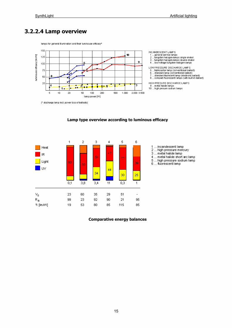
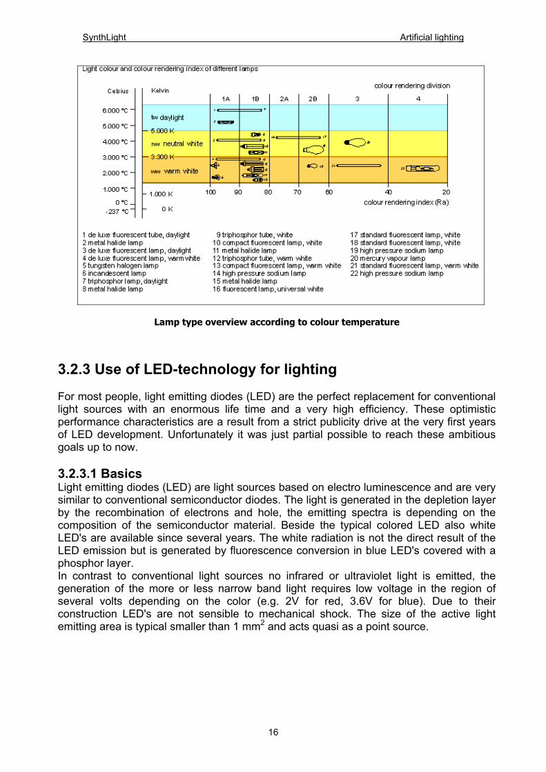
3.2.2.4 Lamp overview
Lamp type overview according to luminous efficacy
Comparative energy balances
15
SynthLight Artificial lighting
Lamp type overview according to colour temperature
3.2.3 Use of LED-technology for lighting For most people, light emitting diodes (LED) are the perfect replacement for conventional light sources with an enormous life time and a very high efficiency. These optimistic performance characteristics are a result from a strict publicity drive at the very first years of LED development. Unfortunately it was just partial possible to reach these ambitious goals up to now. 3.2.3.1 Basics Light emitting diodes (LED) are light sources based on electro luminescence and are very similar to conventional semiconductor diodes. The light is generated in the depletion layer by the recombination of electrons and hole, the emitting spectra is depending on the composition of the semiconductor material. Beside the typical colored LED also white LED's are available since several years. The white radiation is not the direct result of the LED emission but is generated by fluorescence conversion in blue LED's covered with a phosphor layer. In contrast to conventional light sources no infrared or ultraviolet light is emitted, the generation of the more or less narrow band light requires low voltage in the region of several volts depending on the color (e.g. 2V for red, 3.6V for blue). Due to their construction LED's are not sensible to mechanical shock. The size of the active light emitting area is typical smaller than 1 mm2 and acts quasi as a point source.
16
SynthLight Artificial lighting
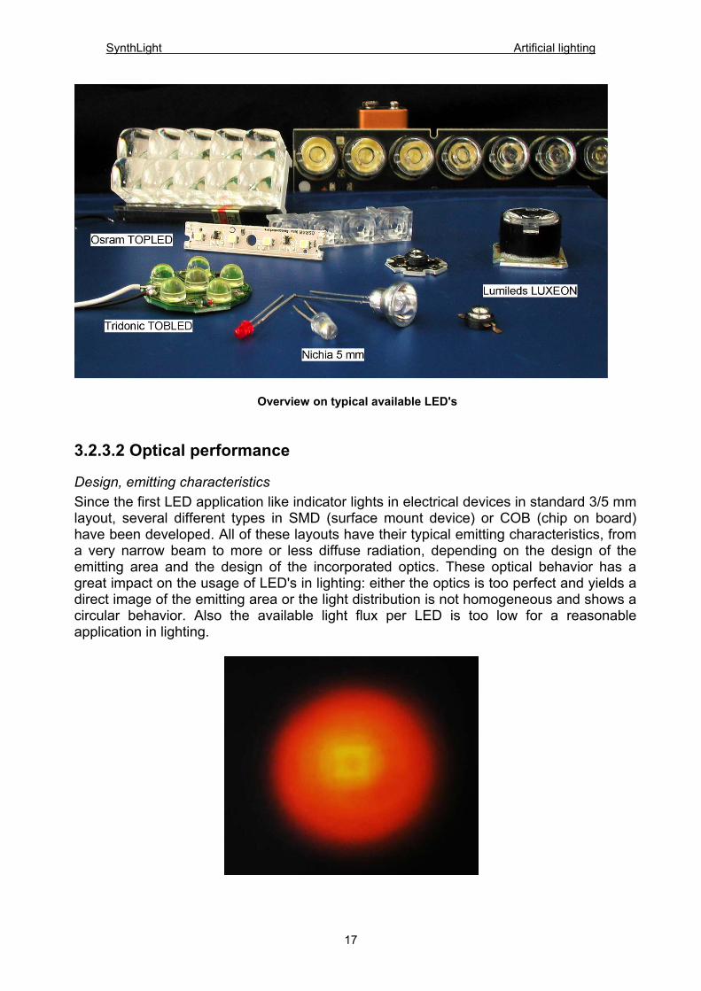
Overview on typical available LED's 3.2.3.2 Optical performance
Design, emitting characteristics Since the first LED application like indicator lights in electrical devices in standard 3/5 mm layout, several different types in SMD (surface mount device) or COB (chip on board) have been developed. All of these layouts have their typical emitting characteristics, from a very narrow beam to more or less diffuse radiation, depending on the design of the emitting area and the design of the incorporated optics. These optical behavior has a great impact on the usage of LED's in lighting: either the optics is too perfect and yields a direct image of the emitting area or the light distribution is not homogeneous and shows a circular behavior. Also the available light flux per LED is too low for a reasonable application in lighting.
17
SynthLight Artificial lighting
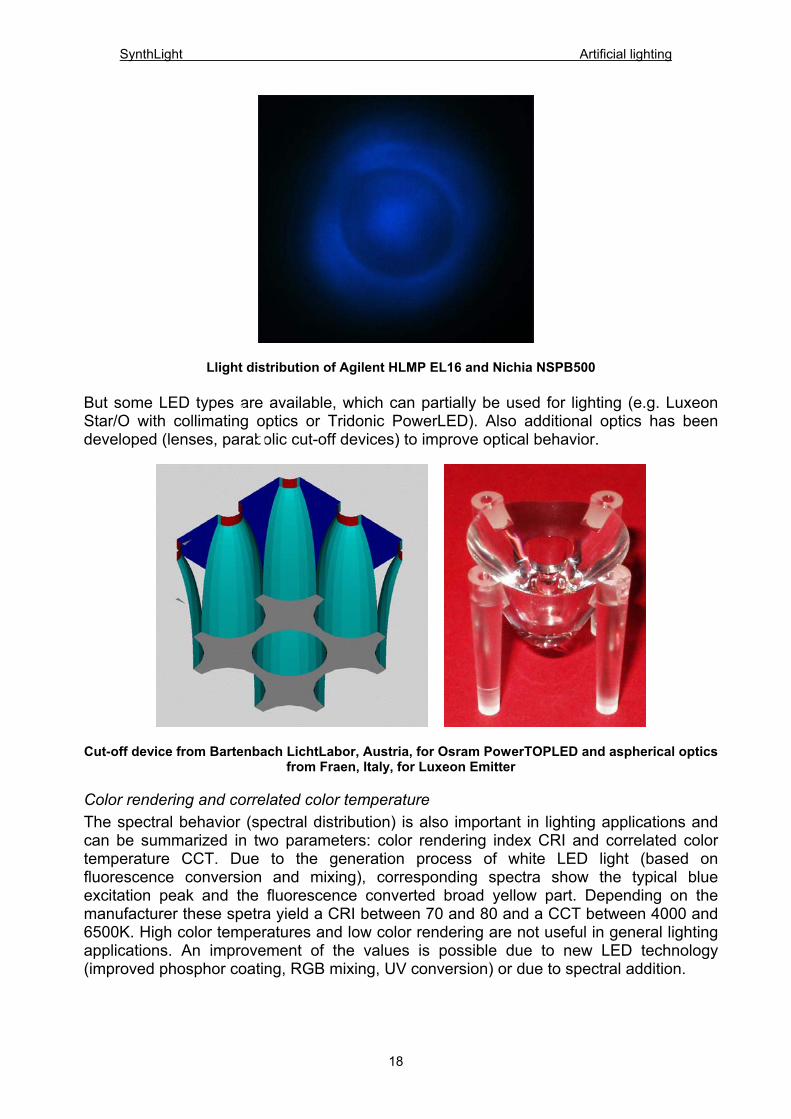
Llight distribution of Agilent HLMP EL16 and Nichia NSPB500
But some LED types are available, which can partially be used for lighting (e.g. Luxeon Star/O with collimating optics or Tridonic PowerLED). Also additional optics has been developed (lenses, parabolic cut-off devices) to improve optical behavior.
Cut-off device from Bartenbach LichtLabor, Austria, for Osram PowerTOPLED and aspherical optics from Fraen, Italy, for Luxeon Emitter
Color rendering and correlated color temperature The spectral behavior (spectral distribution) is also important in lighting applications and can be summarized in two parameters: color rendering index CRI and correlated color temperature CCT. Due to the generation process of white LED light (based on fluorescence conversion and mixing), corresponding spectra show the typical blue excitation peak and the fluorescence converted broad yellow part. Depending on the manufacturer these spetra yield a CRI between 70 and 80 and a CCT between 4000 and 6500K. High color temperatures and low color rendering are not useful in general lighting applications. An improvement of the values is possible due to new LED technology (improved phosphor coating, RGB mixing, UV conversion) or due to spectral addition.
18
SynthLight Artificial lighting
400 450 500 550 600 650 700 750
0,0
0,2
0,4
0,6
0,8
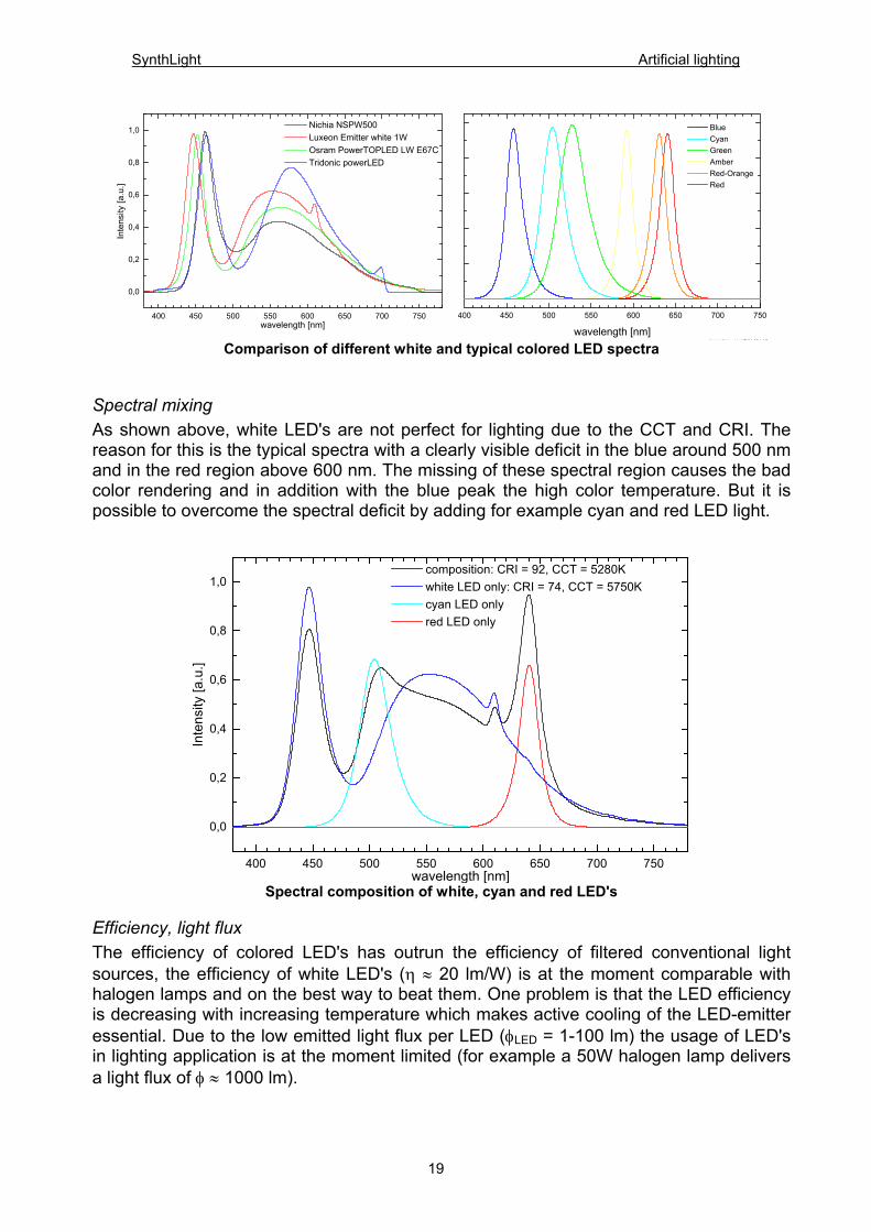
1,0 Nichia NSPW500 Luxeon Emitter white 1W Osram PowerTOPLED LW E67C Tridonic powerLED
Inte
nsity
[a.u
.]
wavelength [nm]
400 450 500 550 600 650 700 750
Li ht W i bj / 17 04 03 / AZ
Blue Cyan Green Amber Red-Orange Red
wavelength [nm] Comparison of different white and typical colored LED spectra
Spectral mixing As shown above, white LED's are not perfect for lighting due to the CCT and CRI. The reason for this is the typical spectra with a clearly visible deficit in the blue around 500 nm and in the red region above 600 nm. The missing of these spectral region causes the bad color rendering and in addition with the blue peak the high color temperature. But it is possible to overcome the spectral deficit by adding for example cyan and red LED light.
400 450 500 550 600 650 700 750
0,0
0,2
0,4
0,6
0,8
1,0 composition: CRI = 92, CCT = 5280K white LED only: CRI = 74, CCT = 5750K cyan LED only red LED only
Inte
nsity
[a.u
.]
wavelength [nm] Spectral composition of white, cyan and red LED's
Efficiency, light flux The efficiency of colored LED's has outrun the efficiency of filtered conventional light sources, the efficiency of white LED's (η ≈ 20 lm/W) is at the moment comparable with halogen lamps and on the best way to beat them. One problem is that the LED efficiency is decreasing with increasing temperature which makes active cooling of the LED-emitter essential. Due to the low emitted light flux per LED (φLED = 1-100 lm) the usage of LED's in lighting application is at the moment limited (for example a 50W halogen lamp delivers a light flux of φ ≈ 1000 lm).
19

SynthLight Artificial lighting
3.2.3.3 Life time Based on the very first estimations, an extrem LED life time with 100.000 h and a more or less endless light output is in all mind. Maybe this is correct for underpowered red or green 5mm indicator LED's but not for white LED's. Latest measurements reveal a life time of 7.000 – 10.000 h for standard 5mm white LED. The reason therefore is a haze in the covering epoxy due to the cracking of the polymer molecules by the emitted blue light. 3.2.3.4 Power supply, circuitry Despite advertisement, LED's are not a simple one-to-one replacement for conventional light sources, the circuitry is more complex due to strict voltage and current restrictions and due to the polarity. But complete solutions with LED modules and appropriate power supplies are available from several manufacturers. This simple plug and play solutions are very efficient for several applications like effect or color lighting. For prototype applications these ready solutions are mostly not useful, custom made power supplies are necessary. Also special types of dimmable power supplies are available.
3.2.3.5 Measurement Classic measurement techniques in lighting business is based on broad band detection cells optimized for conventional light sources light incandescent lamps. These detection cells are modified to follow the spectral response of the human eye by incorporating special filters. The measured brightness reproduce our subjective perception by an averaged detection in the spectral region between 380 – 780 nm. This averaged detection results in a more are less accurate measurement for broadband and spectral smooth light sources. In case of narrow band LED emission, especially in the blue and red region, the detection filter exhibit a deviation from the photopic luminous efficiency function which cause a substantial detection error which must be taken into account for an accurate analysis. If accurate LED measurements are required, the spectral composition of the LED light source as well as the spectral response of the detector is required. In addition to the inherent measurement uncertainties, at the time no international standards are existing. The CIE is at present the only organization which has released guidelines for LED measurements (CIE 127-1997 "measurements of LED's").
350 400 450 500 550 600 650 700 750 8001E-4
1E-3
0,01
0,1
1 measuring cell v(λ)
spec
tral r
espo
nse
wavelenght [nm] 450 500 550 600 650 700
-100
-50
0
50
100
rela
tive
resp
onse
erro
r [%
]
wavelength [nm] Spectral response of a typical light measuring cell and deviation from the CIE luminous efficiency
curve
20
SynthLight Artificial lighting
3.3 LUMINAIRES 3.3.1 INTRODUCTION A luminaire is a complete lighting unit consisting of one or more lamps (light sources) together with optical and mechanical components. It is designed to operate the lamps, that means to position and protect the lamps and to connect them to the power supply. The main function of a luminaire is to realise a lighting concept which fulfils the visual task. It does not suffice to merely achieve the recommended minimum lighting intensities (in keeping with the standards). To allow light to convey visual information, luminaires must generate a balanced distribution of brightness and/or luminance in connection with the right choice of finishes for the space-defining surfaces (ambience). From the viewpoint of a lighting designer, high-quality-luminaires must satisfy all - Photometric requirements (distribution of luminous flux, luminaire efficiency, limitation of glare, ...), - Technical requirements (protection classes, safety of operation...). Due to the increasing cost of electricity in the past decades, increasing demands are being made on the energy-efficiency of luminaires. For this reason, efficiency should be taken into consideration with regard to the choice of materials (reflectance values), reflector design (luminaire efficiency), production (simple and cheap manufacturing methods), components (electronic ballasts), simple and quick assembly, installation, maintenance and cleaning (light loss). In addition, the luminaire is a visible part of the architecture and should therefore satisfy the aesthetic and formal requirements of interior and exterior space and fit in with the surroundings.
3.3.2 Photometric requirements The photometric properties of a luminaire can be defined by the following features: a) Luminous intensity distribution b) Luminous flux distribution c) Luminaire efficiency d) Luminance distribution To be able to correctly assess a luminaire according to the lighting requirements, all of the features mentioned above must be known. An assessment on the basis of just one of the properties mentioned above can be completely misleading. If glare reduction is evaluated without taking the luminous efficiency into consideration, minimum lighting intensities might not be achieved. This would exclude the implementation of such a luminaire.
21
SynthLight Artificial lighting
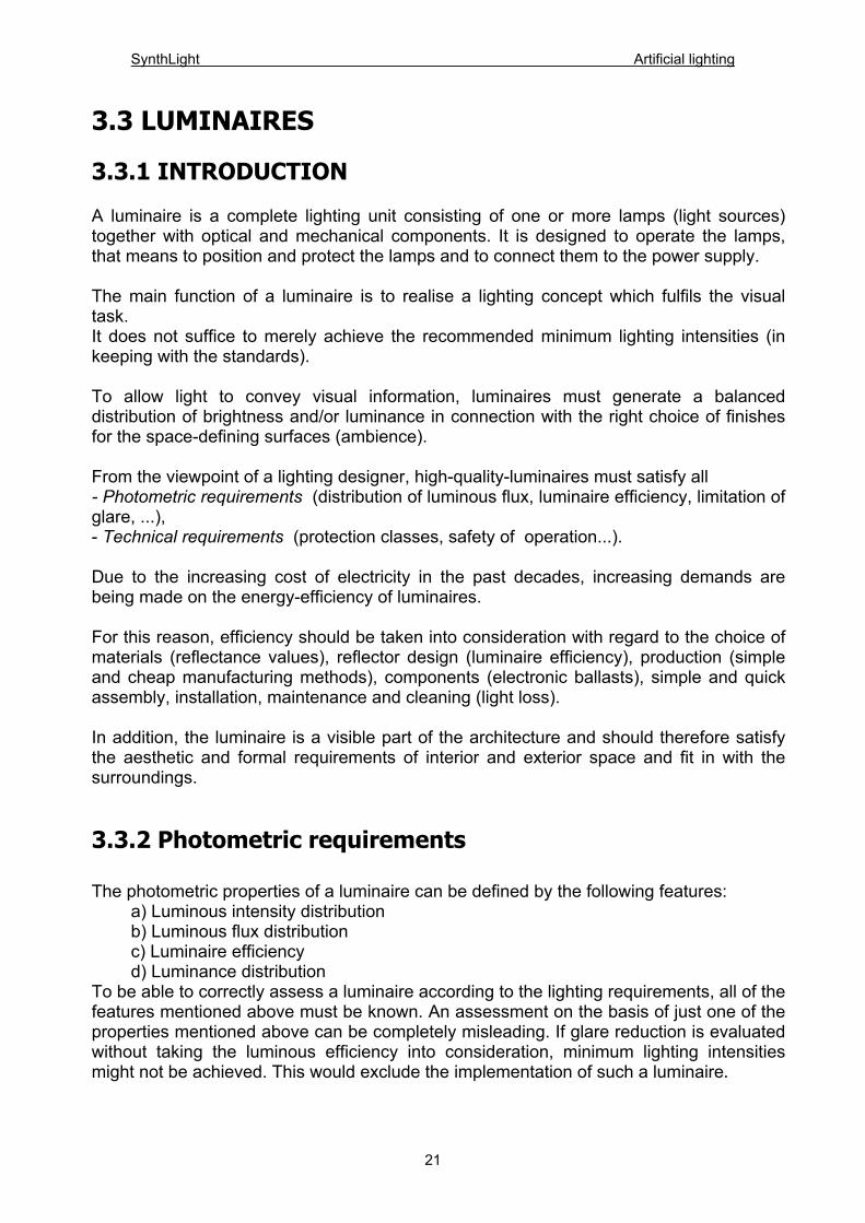
3.3.2.1 Luminous intensity distribution The luminous intensity distribution (LID) indicates the three-dimensional distribution of the luminous flux of a luminaire. To plot the three-dimensional characteristics on paper (that is two-dimensionally), the LID is represented as a curve in various cutting planes.
Three-dimensional LID
In catalogues, mainly polar diagrams are used. The angle of radiation for each cutting plane is plotted in a circle. The value of the luminous intensity emitted is plotted as a length for each angle of radiation. These values are joined to form a polar cutting curve.
22

SynthLight Artificial lighting
23
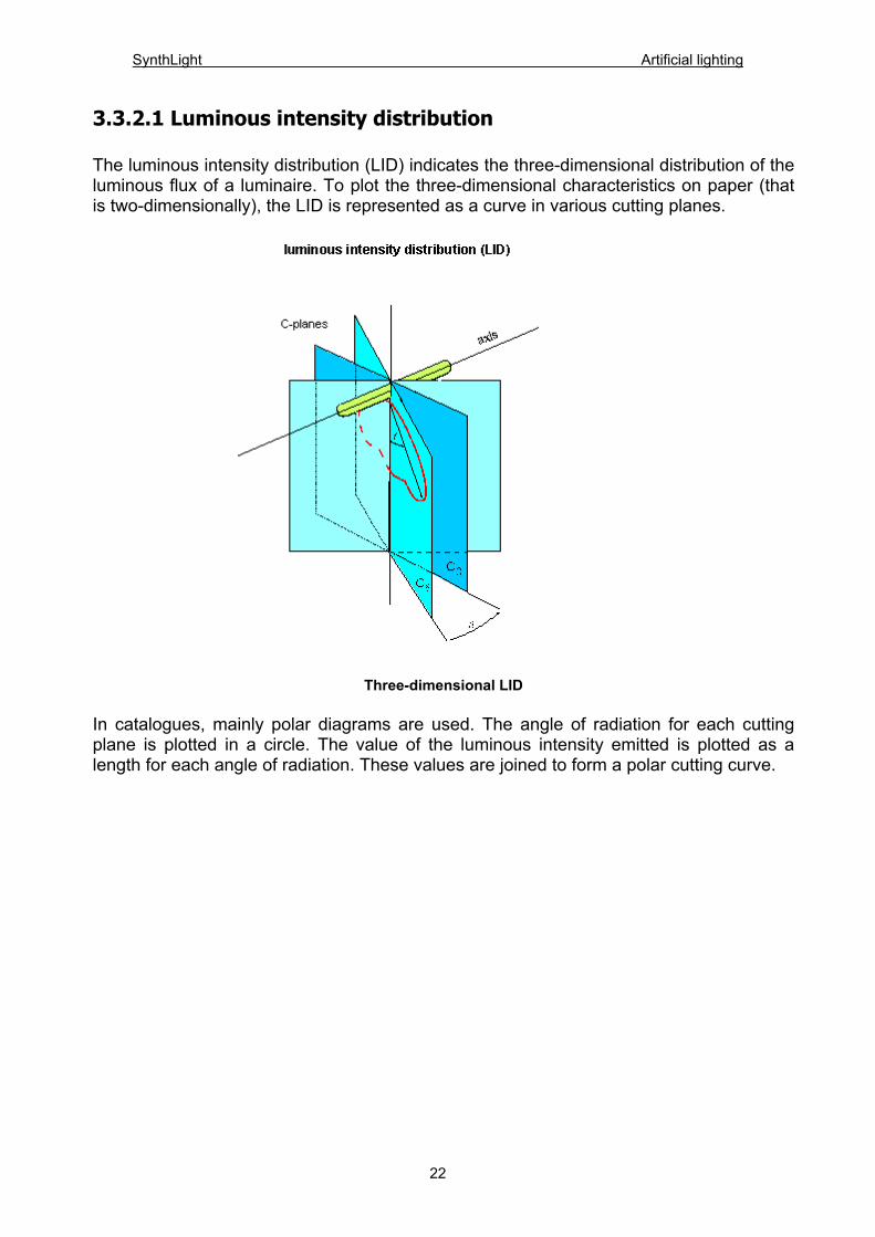
Polar diagram of luminous intensity distribution In addition to polar diagrams, cartesian diagrams are also used. The angles of radiation are plotted on the x-axis, the corresponding values of luminous intensity on the y-axis. The advantage of this diagram lies in the possibility to read off and plot the values of luminaires with a very narrow beam of radiation (spotlights).
SynthLight Artificial lighting
24
Cartesian diagram of luminous intensity distibution
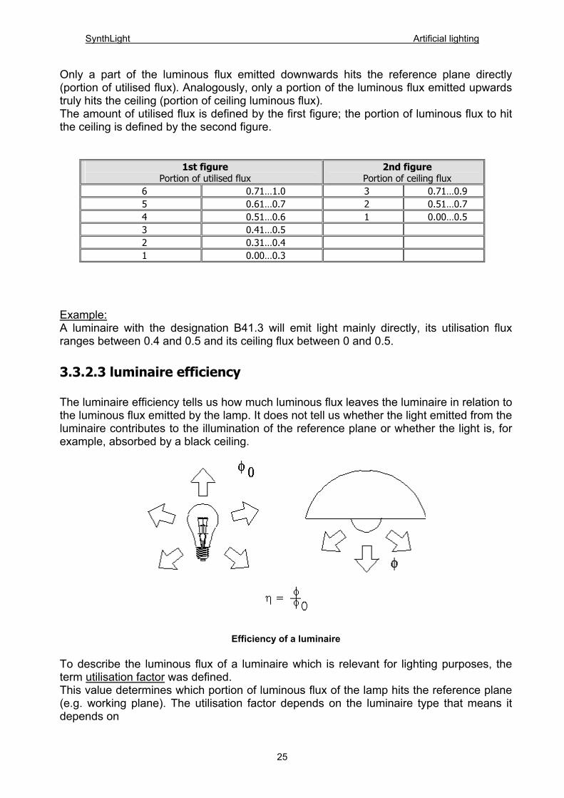
3.3.2.2 Luminous flux distribution When designing light, an important requirement is to achieve a specific illuminance value on a reference plane. The luminous flux hitting this surface can hit this plane directly and/or indirectly by reflection off a space-defining surface. Depending on the reflectance value of these space-defining surfaces, light will be absorbed. For this reason the radiant zone is divided into a lower half-space and an upper half-space. Acording to the portion of luminous flux emitted in the individual areas, the luminaires are designated with a letter. (Example according DIN recommendations)
Luminous flux in % in
Designation Luminaire type
Lower half space Upper half-space A Direct 100...90
B Mainly direct 90... 60 0 .. 10
C Uniform 40... 10 10 .. 40
D Mainly indirect 40... 10 40 .. 60
E Indirect 10.....0 90 ..100
SynthLight Artificial lighting
Only a part of the luminous flux emitted downwards hits the reference plane directly (portion of utilised flux). Analogously, only a portion of the luminous flux emitted upwards truly hits the ceiling (portion of ceiling luminous flux). The amount of utilised flux is defined by the first figure; the portion of luminous flux to hit the ceiling is defined by the second figure.
1st figure Portion of utilised flux
2nd figure Portion of ceiling flux
6 0.71…1.0 3 0.71…0.9 5 0.61…0.7 2 0.51…0.7 4 0.51…0.6 1 0.00…0.5 3 0.41…0.5 2 0.31…0.4 1 0.00…0.3
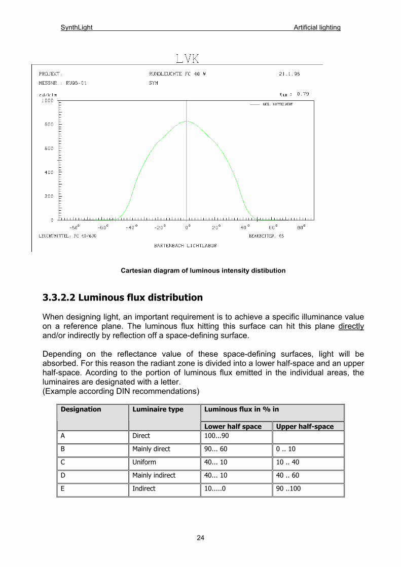
Example: A luminaire with the designation B41.3 will emit light mainly directly, its utilisation flux ranges between 0.4 and 0.5 and its ceiling flux between 0 and 0.5. 3.3.2.3 luminaire efficiency The luminaire efficiency tells us how much luminous flux leaves the luminaire in relation to the luminous flux emitted by the lamp. It does not tell us whether the light emitted from the luminaire contributes to the illumination of the reference plane or whether the light is, for example, absorbed by a black ceiling.
Efficiency of a luminaire To describe the luminous flux of a luminaire which is relevant for lighting purposes, the term utilisation factor was defined. This value determines which portion of luminous flux of the lamp hits the reference plane (e.g. working plane). The utilisation factor depends on the luminaire type that means it depends on
25
SynthLight Artificial lighting
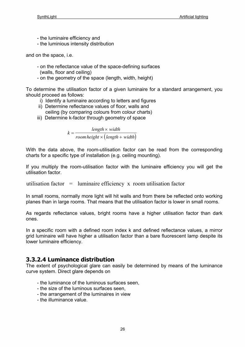
- the luminaire efficiency and - the luminious intensity distribution and on the space, i.e. - on the reflectance value of the space-defining surfaces (walls, floor and ceiling) - on the geometry of the space (length, width, height) To determine the utilisation factor of a given luminaire for a standard arrangement, you should proceed as follows: i) Identify a luminaire according to letters and figures ii) Determine reflectance values of floor, walls and ceiling (by comparing colours from colour charts) iii) Determine k-factor through geometry of space
( )klength width
roomheight length width=
×
× +
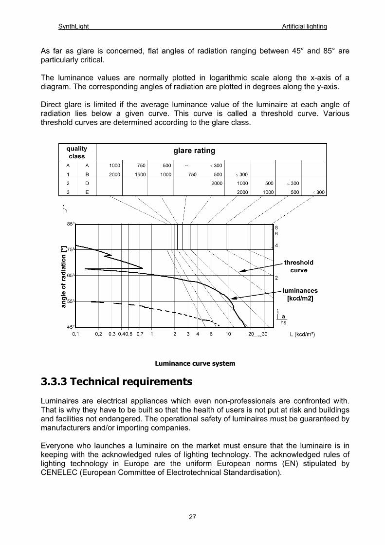
With the data above, the room-utilisation factor can be read from the corresponding charts for a specific type of installation (e.g. ceiling mounting). If you multiply the room-utilisation factor with the luminaire efficiency you will get the utilisation factor. utilisation factor = luminaire efficiency x room utilisation factor In small rooms, normally more light will hit walls and from there be reflected onto working planes than in large rooms. That means that the utilisation factor is lower in small rooms. As regards reflectance values, bright rooms have a higher utilisation factor than dark ones. In a specific room with a defined room index k and defined reflectance values, a mirror grid luminaire will have higher a utilisation factor than a bare fluorescent lamp despite its lower luminaire efficiency. 3.3.2.4 Luminance distribution The extent of psychological glare can easily be determined by means of the luminance curve system. Direct glare depends on - the luminance of the luminous surfaces seen, - the size of the luminous surfaces seen, - the arrangement of the luminaires in view - the illuminance value.
26
SynthLight Artificial lighting
As far as glare is concerned, flat angles of radiation ranging between 45° and 85° are particularly critical. The luminance values are normally plotted in logarithmic scale along the x-axis of a diagram. The corresponding angles of radiation are plotted in degrees along the y-axis. Direct glare is limited if the average luminance value of the luminaire at each angle of radiation lies below a given curve. This curve is called a threshold curve. Various threshold curves are determined according to the glare class.
Luminance curve system
3.3.3 Technical requirements Luminaires are electrical appliances which even non-professionals are confronted with. That is why they have to be built so that the health of users is not put at risk and buildings and facilities not endangered. The operational safety of luminaires must be guaranteed by manufacturers and/or importing companies. Everyone who launches a luminaire on the market must ensure that the luminaire is in keeping with the acknowledged rules of lighting technology. The acknowledged rules of lighting technology in Europe are the uniform European norms (EN) stipulated by CENELEC (European Committee of Electrotechnical Standardisation).
27
SynthLight Artificial lighting
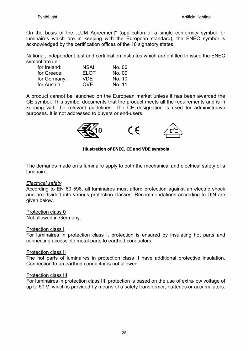
On the basis of the „LUM Agreement" (application of a single conformity symbol for luminaires which are in keeping with the European standard), the ENEC symbol is acknowledged by the certification offices of the 18 signatory states. National, independent test and certification institutes which are entitled to issue the ENEC symbol are i.e.: for Ireland: NSAI No. 06 for Greece: ELOT No. 09 for Germany: VDE No. 10 for Austria: ÖVE No. 11 A product cannot be launched on the European market unless it has been awarded the CE symbol. This symbol documents that the product meets all the requirements and is in keeping with the relevant guidelines. The CE designation is used for administrative purposes. It is not addressed to buyers or end-users.
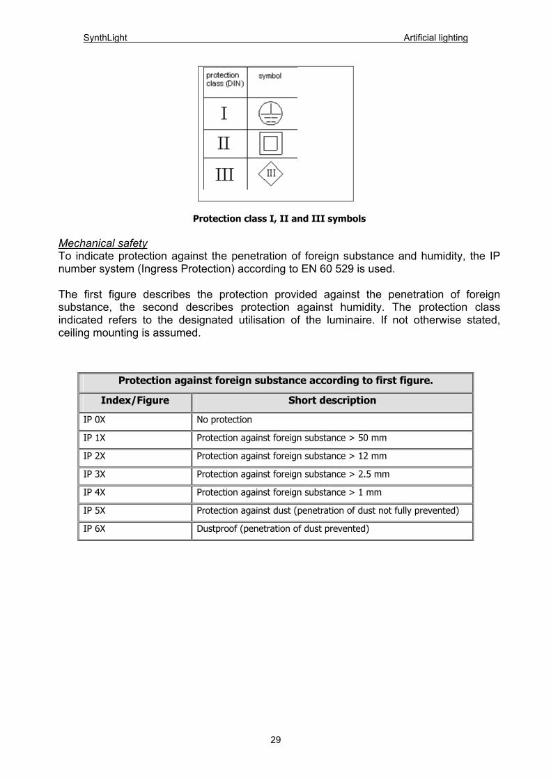
Illustration of ENEC, CE and VDE symbols The demands made on a luminaire apply to both the mechanical and electrical safety of a luminaire. Electrical safety According to EN 60 598, all luminaires must afford protection against an electric shock and are divided into various protection classes. Recommendations according to DIN are given below. Protection class 0 Not allowed in Germany. Protection class I For luminaires in protection class I, protection is ensured by insulating hot parts and connecting accessible metal parts to earthed conductors. Protection class II The hot parts of luminaires in protection class II have additional protective insulation. Connection to an earthed conductor is not allowed. Protection class III For luminaires in protection class III, protection is based on the use of extra-low voltage of up to 50 V, which is provided by means of a safety transformer, batteries or accumulators.
28
SynthLight Artificial lighting
Protection class I, II and III symbols
Mechanical safety To indicate protection against the penetration of foreign substance and humidity, the IP number system (Ingress Protection) according to EN 60 529 is used. The first figure describes the protection provided against the penetration of foreign substance, the second describes protection against humidity. The protection class indicated refers to the designated utilisation of the luminaire. If not otherwise stated, ceiling mounting is assumed.
Protection against foreign substance according to first figure.
Index/Figure Short description
IP 0X No protection
IP 1X Protection against foreign substance > 50 mm
IP 2X Protection against foreign substance > 12 mm
IP 3X Protection against foreign substance > 2.5 mm
IP 4X Protection against foreign substance > 1 mm
IP 5X Protection against dust (penetration of dust not fully prevented)
IP 6X Dustproof (penetration of dust prevented)
29
SynthLight Artificial lighting
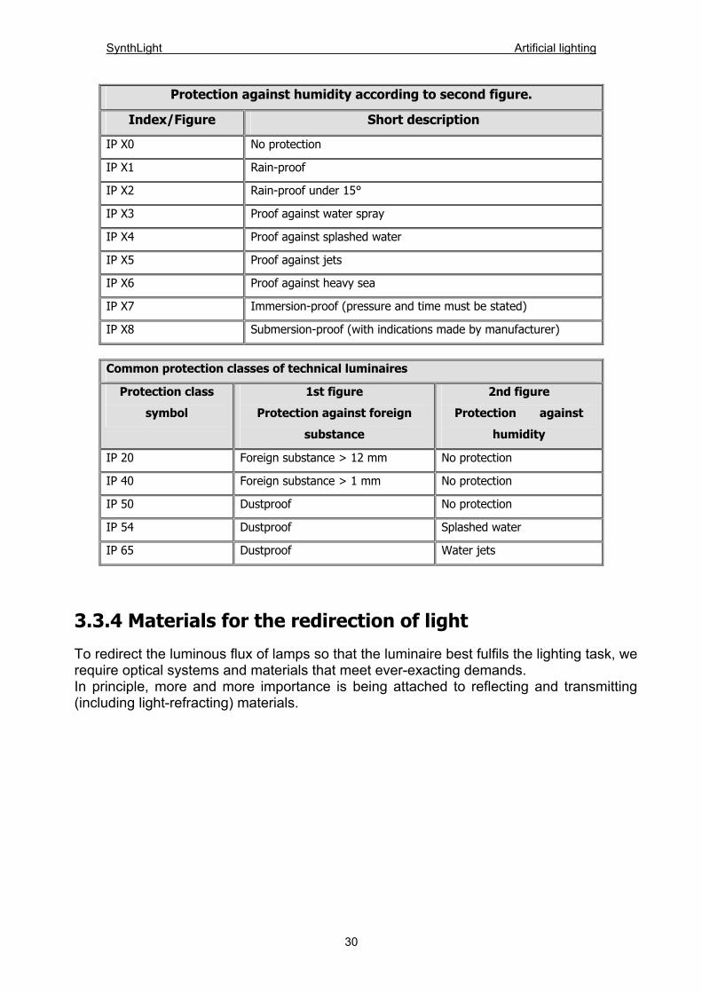
Protection against humidity according to second figure.
Index/Figure Short description
IP X0 No protection
IP X1 Rain-proof
IP X2 Rain-proof under 15°
IP X3 Proof against water spray
IP X4 Proof against splashed water
IP X5 Proof against jets
IP X6 Proof against heavy sea
IP X7 Immersion-proof (pressure and time must be stated)
IP X8 Submersion-proof (with indications made by manufacturer)
Common protection classes of technical luminaires
Protection class
symbol
1st figure
Protection against foreign
substance
2nd figure
Protection against
humidity
IP 20 Foreign substance > 12 mm No protection
IP 40 Foreign substance > 1 mm No protection
IP 50 Dustproof No protection
IP 54 Dustproof Splashed water
IP 65 Dustproof Water jets
3.3.4 Materials for the redirection of light To redirect the luminous flux of lamps so that the luminaire best fulfils the lighting task, we require optical systems and materials that meet ever-exacting demands. In principle, more and more importance is being attached to reflecting and transmitting (including light-refracting) materials.
30
SynthLight Artificial lighting
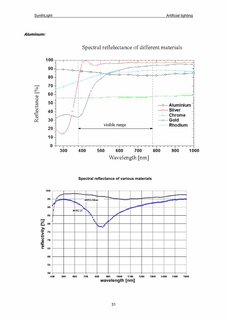
Aluminum:
Spectral reflectance of various materials
31
SynthLight Artificial lighting
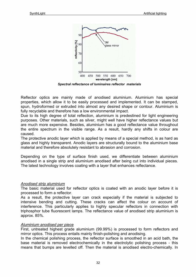
Spectral reflectance of luminaires reflector materials
Reflector optics are mainly made of anodised aluminium. Aluminium has special properties, which allow it to be easily processed and implemented. It can be stamped, spun, hydroformed or extruded into almost any desired shape or contour. Aluminium is fully recyclable and therefore has a low environmental impact. Due to its high degree of total reflection, aluminium is predestined for light engineering purposes. Other materials, such as silver, might well have higher reflectance values but are much more expensive. Besides, aluminium has a good reflectance value throughout the entire spectrum in the visible range. As a result, hardly any shifts in colour are caused. The protective anodic layer which is applied by means of a special method, is as hard as glass and highly transparent. Anodic layers are structurally bound to the aluminium base material and therefore absolutely resistant to abrasion and corrosion. Depending on the type of surface finish used, we differentiate between aluminium anodised in a single strip and aluminium anodised after being cut into individual pieces. The latest technology involves coating with a layer that enhances reflectance. Anodised strip aluminium The basic material used for reflector optics is coated with an anodic layer before it is processed to form a reflector. As a result, the protective layer can crack especially if the material is subjected to intensive bending and cutting. These cracks can affect the colour on account of interference. This particularly applies to highly specular reflectors in connection with triphosphor tube fluorescent lamps. The reflectance value of anodised strip aluminium is approx. 85%. Aluminium anodised per piece First, untreated highest grade aluminium (99.99%) is processed to form reflectors and mirror optics. This process entails mainly finish-polishing and anodising. In the chemical polishing process, the reflector surface is smoothed in an acid bath, the base material is removed electrochemically in the electrolytic polishing process - this means that bumps are levelled off. Then the material is anodised electro-chemically. In
32
SynthLight Artificial lighting
other words, the reflector material is fully coated with a protective layer of aluminium oxide. As a result, reflectors anodised per piece do not have any cracks and are homogenous. Normally, the thickness of the anodic layers applied in this process amount to approx. 10 µm. The reflectance value of aluminium anodised per piece is approx. 85%. Reflectance-enhancing layer The basic material is made of aluminium and vacuum metalised with a layer of highest grade aluminium. A special coating method is then used to apply an additional reflectance-enhancing layer of oxide. As a result, reflectance values can be increased to 95%. The disadvantage is that this method can hardly be applied to already assembled reflectors. Aluminised synthetics In addition to using specular aluminium as a reflector material, various other basic materials can be vacuum metalised with aluminium. After being coated with a protective layer against corrosion, these elements can also be used as reflectors by the luminaire industry. The advantage of metalisation lies in the diversity of materials available because the surface of the basic material does not have to fulfil demanding criteria. The reflectance value of aluminised parts is comparable to that of anodised aluminium strip reflectors amounting to approx. 85%. It is, however, clearly below that of reflectance-enhanced aluminium. From a photometric viewpoint, partial aluminisation of transparent synthetics such as acrylic or polycarbonate is particularly interesting. Due to the higher cost of tools, aluminised plastic reflectors are mainly used where high reflective precision is required and a sufficiently large number of reflectors implemented (i.e. free-shaped faceted field of reflectors for spot/reflector applications).
33
SynthLight Artificial lighting
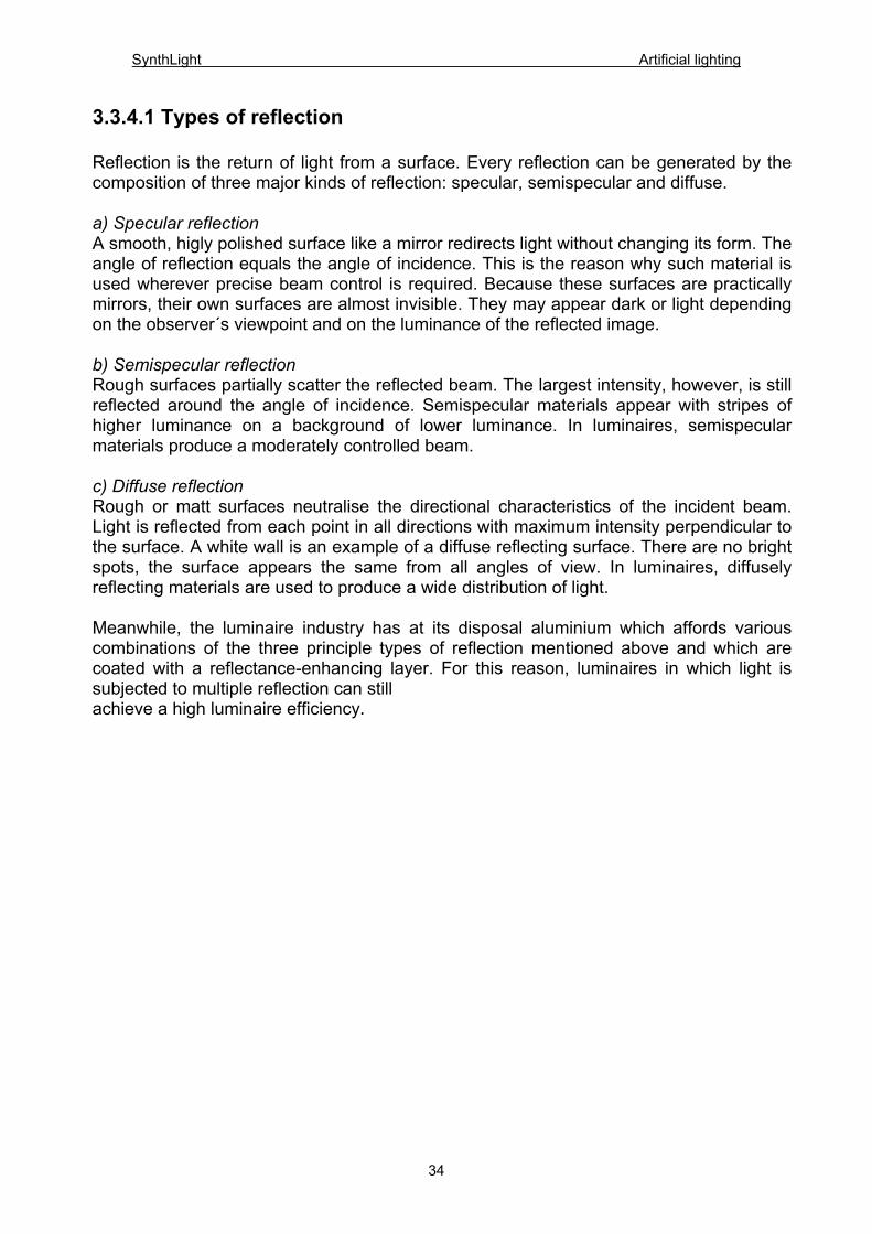
3.3.4.1 Types of reflection Reflection is the return of light from a surface. Every reflection can be generated by the composition of three major kinds of reflection: specular, semispecular and diffuse. a) Specular reflection A smooth, higly polished surface like a mirror redirects light without changing its form. The angle of reflection equals the angle of incidence. This is the reason why such material is used wherever precise beam control is required. Because these surfaces are practically mirrors, their own surfaces are almost invisible. They may appear dark or light depending on the observer´s viewpoint and on the luminance of the reflected image. b) Semispecular reflection Rough surfaces partially scatter the reflected beam. The largest intensity, however, is still reflected around the angle of incidence. Semispecular materials appear with stripes of higher luminance on a background of lower luminance. In luminaires, semispecular materials produce a moderately controlled beam. c) Diffuse reflection Rough or matt surfaces neutralise the directional characteristics of the incident beam. Light is reflected from each point in all directions with maximum intensity perpendicular to the surface. A white wall is an example of a diffuse reflecting surface. There are no bright spots, the surface appears the same from all angles of view. In luminaires, diffusely reflecting materials are used to produce a wide distribution of light. Meanwhile, the luminaire industry has at its disposal aluminium which affords various combinations of the three principle types of reflection mentioned above and which are coated with a reflectance-enhancing layer. For this reason, luminaires in which light is subjected to multiple reflection can still achieve a high luminaire efficiency.
34
SynthLight Artificial lighting
35
Types of reflection: Specular, semispecular and diffuse reflection
SynthLight Artificial lighting
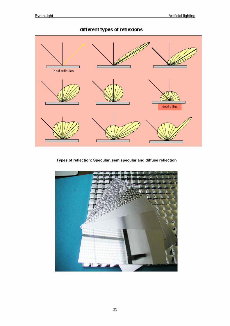
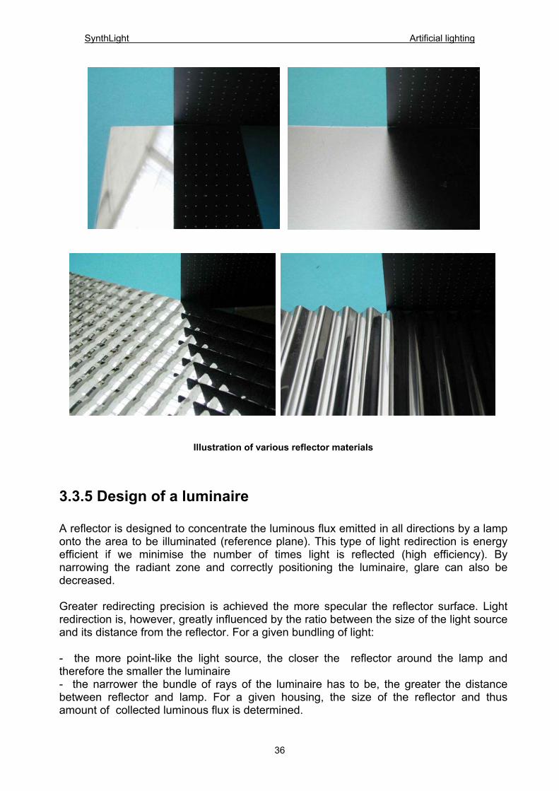
Illustration of various reflector materials 3.3.5 Design of a luminaire A reflector is designed to concentrate the luminous flux emitted in all directions by a lamp onto the area to be illuminated (reference plane). This type of light redirection is energy efficient if we minimise the number of times light is reflected (high efficiency). By narrowing the radiant zone and correctly positioning the luminaire, glare can also be decreased. Greater redirecting precision is achieved the more specular the reflector surface. Light redirection is, however, greatly influenced by the ratio between the size of the light source and its distance from the reflector. For a given bundling of light: - the more point-like the light source, the closer the reflector around the lamp and therefore the smaller the luminaire - the narrower the bundle of rays of the luminaire has to be, the greater the distance between reflector and lamp. For a given housing, the size of the reflector and thus amount of collected luminous flux is determined.
36
SynthLight Artificial lighting
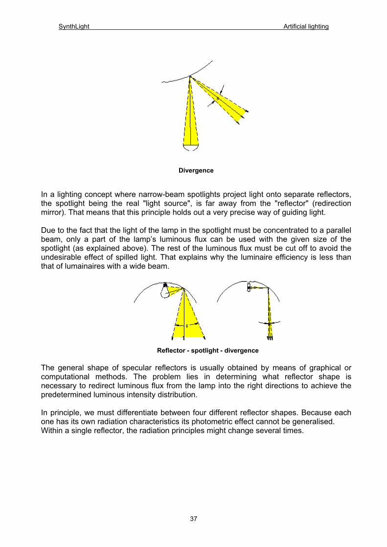
Divergence In a lighting concept where narrow-beam spotlights project light onto separate reflectors, the spotlight being the real "light source", is far away from the "reflector" (redirection mirror). That means that this principle holds out a very precise way of guiding light. Due to the fact that the light of the lamp in the spotlight must be concentrated to a parallel beam, only a part of the lamp’s luminous flux can be used with the given size of the spotlight (as explained above). The rest of the luminous flux must be cut off to avoid the undesirable effect of spilled light. That explains why the luminaire efficiency is less than that of lumainaires with a wide beam.
Reflector - spotlight - divergence
The general shape of specular reflectors is usually obtained by means of graphical or computational methods. The problem lies in determining what reflector shape is necessary to redirect luminous flux from the lamp into the right directions to achieve the predetermined luminous intensity distribution. In principle, we must differentiate between four different reflector shapes. Because each one has its own radiation characteristics its photometric effect cannot be generalised. Within a single reflector, the radiation principles might change several times.
37
SynthLight Artificial lighting
38
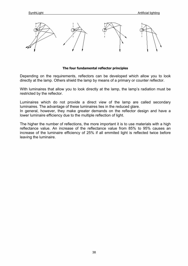
The four fundamental reflector principles
Depending on the requirements, reflectors can be developed which allow you to look directly at the lamp. Others shield the lamp by means of a primary or counter reflector. With luminaires that allow you to look directly at the lamp, the lamp’s radiation must be restricted by the reflector. Luminaires which do not provide a direct view of the lamp are called secondary luminaires. The advantage of these luminaires lies in the reduced glare. In general, however, they make greater demands on the reflector design and have a lower luminaire efficiency due to the multiple reflection of light. The higher the number of reflections, the more important it is to use materials with a high reflectance value. An increase of the reflectance value from 85% to 95% causes an increase of the luminaire efficiency of 25% if all emmited light is reflected twice before leaving the luminaire.
SynthLight Artificial lighting
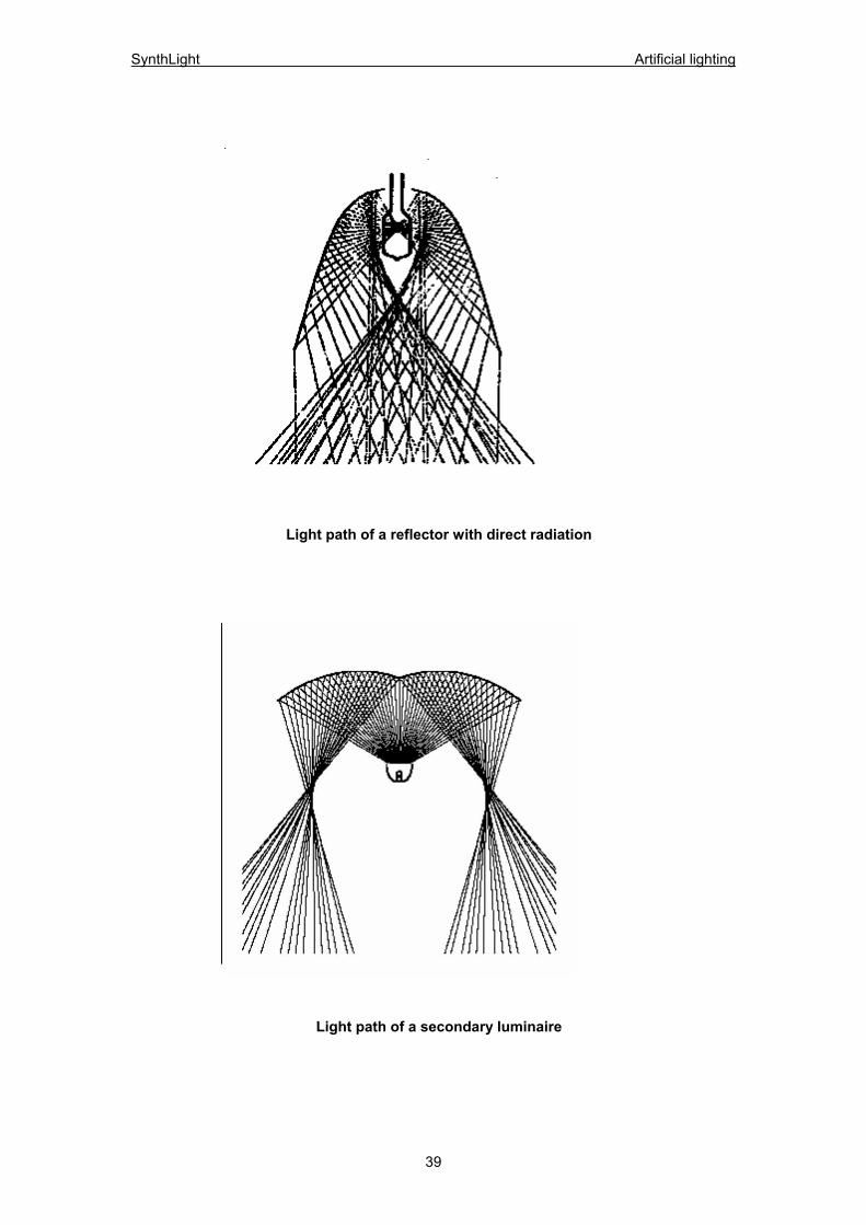
Light path of a reflector with direct radiation
Light path of a secondary luminaire
39
SynthLight Artificial lighting
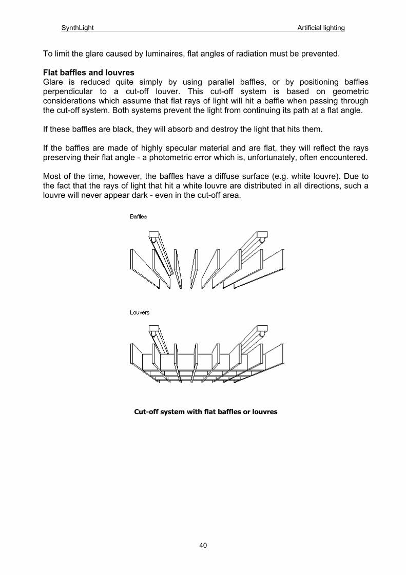
To limit the glare caused by luminaires, flat angles of radiation must be prevented. Flat baffles and louvres Glare is reduced quite simply by using parallel baffles, or by positioning baffles perpendicular to a cut-off louver. This cut-off system is based on geometric considerations which assume that flat rays of light will hit a baffle when passing through the cut-off system. Both systems prevent the light from continuing its path at a flat angle. If these baffles are black, they will absorb and destroy the light that hits them. If the baffles are made of highly specular material and are flat, they will reflect the rays preserving their flat angle - a photometric error which is, unfortunately, often encountered. Most of the time, however, the baffles have a diffuse surface (e.g. white louvre). Due to the fact that the rays of light that hit a white louvre are distributed in all directions, such a louvre will never appear dark - even in the cut-off area.
Cut-off system with flat baffles or louvres
40
SynthLight Artificial lighting
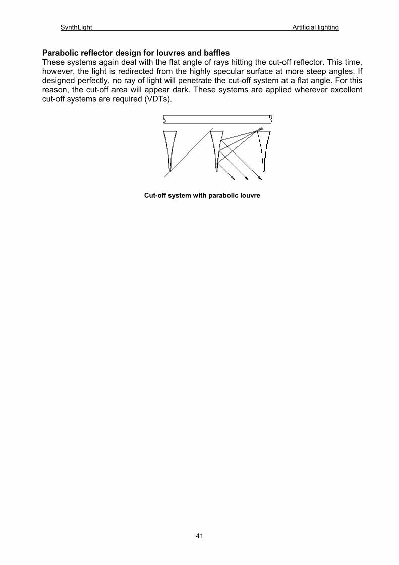
Parabolic reflector design for louvres and baffles These systems again deal with the flat angle of rays hitting the cut-off reflector. This time, however, the light is redirected from the highly specular surface at more steep angles. If designed perfectly, no ray of light will penetrate the cut-off system at a flat angle. For this reason, the cut-off area will appear dark. These systems are applied wherever excellent cut-off systems are required (VDTs).
Cut-off system with parabolic louvre
41
SynthLight Artificial lighting
3.4 LIGHTING DESIGN Man uses above all his eyes to orient himself - his surroundings are a world of vision. The eye is the most important sense organ, which takes in approx. 80% of all information. This would, however, be impossible without light. Light is the medium that makes visual perception possible. Light does not, however, only serve vision it also greatly influences our well-being and our mood. Lighting intensity, light colour, the casting of shadows and the transition from light to dark all affect momentary sensations and determine the rhythm of life. The goal of good lighting design is to ensure the right distribution of brightness, i.e. adjusted to the visual task, in the surroundings of the observer. The energy crisis of the early 70s, the increasing cost of energy, the dwindling of certain sources of energy and concern for our environment have not gone unnoticed and have also affected lighting design. Thus, a lighting system should not waste energy providing more light than is needed, nor should it use inefficient systems if more efficient ones (within the whole budget of capital and running costs) can do the same task. Although energy efficience is important, it should never be seen as the principle measure of good lighting if it excessively compromises functional or aesthetic considerations. This chapter first lists lighting design steps which can help the designer/engineer to generate a good lighting design. Before giving recommendations for installing energy-saving illumination systems, important design criteria are discussed in detail. This is very important because ignoring these would lead to many unacceptable lighting installations. Finally, a few executed projects are shown by means of photos.
3.4.1 Project analysis During this initial phase the lighting designer gathers information about the needs, preferences and constraints of the owner, the client and the user. From the owner, basic information concerning image, maintenance, flexibility, life span and budget must be collected. Information on higher design goals, spatial relationships, must be gathered. Furthermore the integration of various design disciplines must be considered. Additionally, the interior designer must provide information according to space utilisation, special interior properties. This information is exchanged in meetings, written inquiries or telephone conversations. Good communication among all parties during all phases is of particular importance. Often the lighting designer visits the client on site to get further information on the visual tasks involved. Understanding the process of visual perception, knowing the nature of the visual task required, demands on speed and accuracy are absolutely necessary because they all affect and determine the lighting design objectives.
42
SynthLight Artificial lighting
Lighting design does not stand-alone - the realisation of creating a balanced luminous environment that meets the requirements of the visual task is a process that is affected by all other disciplines. Therefore, it is necessary to define the project objectives and their later realisation in mutual agreement. After a detailed analysis, the lighting designer should be able to answer the following exemplary questions concerning qualitative and quantitative objectives:
3.4.1.1 Qualitative objectives 1. Visual guides Highlighting specific areas, creating subtle differences in brightness can provide visual cues to guide users through space. For example, traffic zones like long corridors can be structured in the right way that means that important areas such as intersections are accentuated with a high level of illuminance. A hierarchy of visual focus should be installed. Therefore, designing darker areas can be helpful, too. 2. Perceived brightness The perceived brightness depends on the reflectance value of all space defining surfaces; it is also affected by the luminance contrast and the viewer’s position. Furthermore, the perceived brightness depends on the luminous intensity distribution of installed luminaires and the achieved illuminance level. Horizontal versus vertical illuminance can greatly affect perceived brightness. 3. Architectural emphasis Architectural characteristics can be emphasised or extenuated according to the kind of illumination. For example, a flat angle of incidence towards a structured facade generates strong shadow castings to underline the structure. The height of a room can be visually increased if the ceiling is illuminated. 4. Colour Colour characteristics including colour temperature and colour rendering affect visual perception. An important part of the lighting design process is the selection of appropriate lamps. 5. Design style The style of luminaires and their lighting characteristics can help the interior designer to create different environments. The look of a space can be modified to appear more technical or more stately. 6. Image The way a facility is illuminated has a big influence on its image. By means of different kinds of illumination a space can be made to look more inviting or more forbidding. Glare, luminaire type, colour, intensity and distribution modify the look of a space and thus affect the image.
43
SynthLight Artificial lighting
3.4.1.2 Quantitative objectives 1. Illuminance level The appropriate illuminance level for the required task has to be defined. Therefore, recommendations of lighting organisations provide helpful information. 2. Daylight The amount of daylight penetrating into the space has to be considered. Especially when VDUs are used, the limitation of daylight should be taken into consideration to achieve appropriate luminance levels. If this can be guaranteed, daylight can contribute to the illuminance level and help to reduce artificial illumination proportionally. 3. Flexibility According to different tasks, the composition of teams within an office can change. Therefore a physical change in the client’s organisation can be necessary and should be considered. 4. Maintenance Maintenance characteristics of luminaires, lamps and design must be considered. Of particular importance is accessibility for relamping and cleaning because this affects operating costs. 3.4.2 Developing the lighting concept Based on the analysis, the objectives of the project should be defined. Now the lighting designer can start to think about which lighting concept is able to fulfil all requirements. Because there are so many aspects to weigh up, there is not only one perfect solution. There are a multitude of solutions but before continuing each solution has to be verified to be within reasonable constraints and budget. Next is to convey the lighting designer’s ideas to other project partners. Various tools can support this communication process including: - scale models - photos - renderings - charts - drawings - written and/or verbal descriptions... Furthermore, visits of finished projects with similar installations give both the owner/architect and the lighting designer the possibility on site to explain ideas, to express wishes what is liked and what is not.
44
SynthLight Artificial lighting
3.4.3 Design development Once the concept is established and agreed on by all project partners, the lighting designer is now ready to formulate design concepts. According to the special requirements of the area, the lighting designer determines the appropriate distribution of light, the direction of light and light sources. Light may be emitted from a luminaire in a concentrated beam causing strong shadows or as a diffuse wash avoiding shadows. The light source can be a point source (i.e. tungsten halogen lamp), a linear source (i.e fluorescent lamp). The luminaire may be visible or concealed. It may be recessed, wall mounted or suspended from the ceiling. Such requirements guide the lighting designer toward specific lighting products. Lighting design concepts derived during this process must be evaluated as regards the project constraints and, of course, must be within budget. During this phase, mounting details are developed, more detailed lighting calculations are done and energy consumption considered. To judge if a selected luminaire meets all requirement, a thorough understanding of the luminire´s photometric data is necessary. In case a desired luminaire does not exist to fulfil the objectives of the project, the designer must be able to formulate the requirements of a luminaire in technical terms like i.e. appropriate luminous intensity distribution, luminaire efficiency, utilisation factor. The designer should be aware that custom-made luminaires have potential problems that standard products may not have i.e. long delivery time, additional costs for production due to low number of pieces or special reflectors. Therefore, extensive communication and coordination with all partners (architect, interior designer, engineers) is necessary to ensure that the lighting system is integrated in the building. 3.4.4 Contract documents During this phase, great effort is necessary to prepare numerous documents, charts and drawings which are complete and unambiguous for the electrical contractor to bid the project. This comprises ordering the lighting, checking products and installation. As far as custom-made luminaires are concerned, additional documents have to be computed. These documents may vary from project to project, but normally the following is included.
- Electrical lighting plan (which is usually a modified reflected ceiling plan) to demonstrate the locations and types of luminaires. Control locations and circuits can be shown on the lighting plan, too.
- Drawings showing details of mounting, luminaire details and further information - Required photometric data, i.e. luminaire efficiency, luminous intensity distribution - Lighting specifications to define general requirements for the lighting system.
45
SynthLight Artificial lighting
- Dimming and control specifications - Surface properties, housing material requirements - Drawings or photos of luminaires which are used in already executed projects to illustrate
specified luminaires, lamps and controls -...
Sometimes, the lighting designer is engaged to review contract documents prepared by other project partners for co-ordination. Finally the package of lighting documents is turned over to the owner for bidding. 3.4.5 Construction and execution The bid has been awarded to an electrical contractor and/or a manufacturer. Especially when custom-made luminaires are involved, the lighting designer is requested to review drawings to guarantee that the products fulfil the demands of the contract documents. In such cases, the manufacturer is usually requested to deliver a prototype which can be inspected, measured and tested. This provides the lighting designer with basic information to decide whether the product fulfils the project’s requirements and can be mounted or the product has to be redesigned. During a final site visit, the lighting designer may prepare a list which enumerates any errors concerning the production and installation of the lighting products. In cases where precise and absolutely exact radiation is required to fulfil the objectives of the project, it can be necessary to adjust luminaires, spotlights and/or single reflectors. Then the lighting designer returns to make these adjustments on site in order to obtain successful results. 3.4.6 Postoccupancy evaluation The main goal of the postoccupancy evaluation is to determine if the objectives of the project are reached. Therefore important questions have to be answered i.e. is the lighting system appropriate for the different tasks or does the illuminated environment satisfy human needs? If these questions can be answered with yes, the design has stayed within the budget complied with energy constraints and satisfied the objectives of the project. The lighting design has been successful.
46
SynthLight Artificial lighting
3.5 Important design criteria The previous section described a principal method and single steps for creating a good lighting design. When we talk about correct or balanced illumination, we have to guarantee that the illumination meets all given requirements. Therefore, design criteria were developed which allow us to compare different illuminating systems. Every single design criteria must be weighed and judged according to the user’s visual task. The following design criteria mentioned in several national and international lighting design organisations examined more closely. They provide guide values, which should be taken into consideration to avoid major mistakes in lighting design. a) illuminance level b) balanced luminances c) limitation of glare d) direction of light and shadows e) colour of light and colour rendering Depending on the requirements of the visual task, these criteria gain more or less importance. They are of particular significance in offices where VDUs are used. 3.5.1 Illuminance level A luminous flux hitting a surface causes a certain illuminance level. According to our visual perceptions we are only able to see the redirected portion of this light which is closely connected with the surface’s reflectance. The higher the value of the reflectance, the brighter the surface appears. Although luminance plays a dominant role, it is difficult to measure and it often depends on the angle of view. That’s why national institutes and international organisations recommend certain illuminance values that should be achieved throughout use. Illuminance value E: It is the quotient of the luminous flux by the area of the surface. Rated illuminance EN : The rated illuminance lists the illuminance value for a certain task that must be achieved on average all the time in the room (or working area). According to DIN 5035, the position of the plane, where the rated illuminance is measured, depends on the room’s use. In traffic zones like corridors the plane is positioned 20 cm above the floor. In offices the working area is at the height of a desk. Therefore, the plane is positioned 85 cm above the floor.
47
SynthLight Artificial lighting
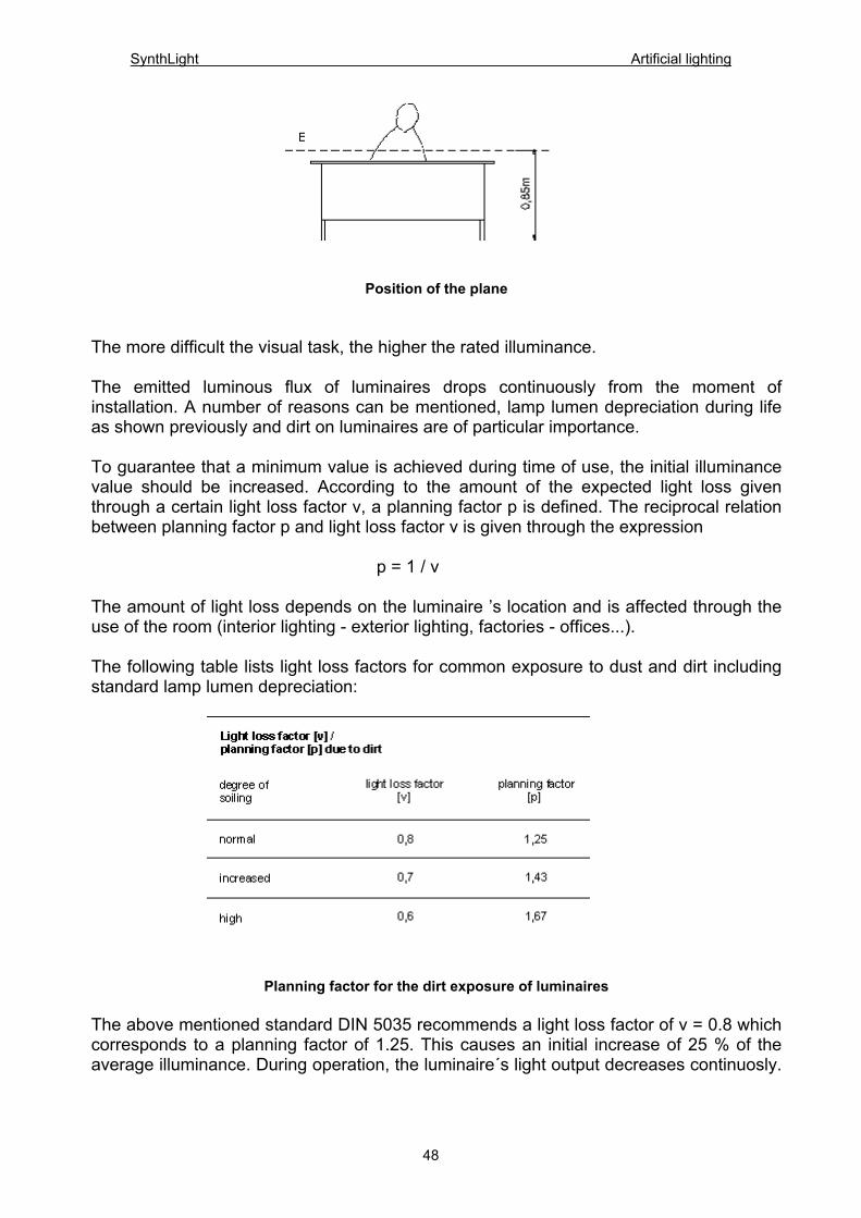
Position of the plane
The more difficult the visual task, the higher the rated illuminance. The emitted luminous flux of luminaires drops continuously from the moment of installation. A number of reasons can be mentioned, lamp lumen depreciation during life as shown previously and dirt on luminaires are of particular importance. To guarantee that a minimum value is achieved during time of use, the initial illuminance value should be increased. According to the amount of the expected light loss given through a certain light loss factor v, a planning factor p is defined. The reciprocal relation between planning factor p and light loss factor v is given through the expression p = 1 / v The amount of light loss depends on the luminaire ’s location and is affected through the use of the room (interior lighting - exterior lighting, factories - offices...). The following table lists light loss factors for common exposure to dust and dirt including standard lamp lumen depreciation:
Planning factor for the dirt exposure of luminaires
The above mentioned standard DIN 5035 recommends a light loss factor of v = 0.8 which corresponds to a planning factor of 1.25. This causes an initial increase of 25 % of the average illuminance. During operation, the luminaire´s light output decreases continuosly.
48
SynthLight Artificial lighting
The moment the average illuminance level is 80% of the rated illuminace, the standards recommends refitting lamps and cleaning luminaires. To prevent this average value from leading to too dark areas and from causing safety defects (i.e. in case of the failure of neighbouring lamps) it is also recommended that the illumination level reach 60% of the rated illuminance at all times. This is an absolute minimum value. 3.5.1.1 Maintenance rate (period) Reality shows us that just by means of maintenances illumination levels reached at the moment of installation cannot be perpetuated during operation. Thus, times of relamping and maintenance periods should be used to eliminate all negative influences that occur during operation. Therefore it is meaningful to increase the planning factor in cases of dusty surroundings and in difficult maintenance situations (i.e. difficult access, height,...). This increases the periods of maintenance that is particularly important when maintenance costs are high. If the average illuminance value on a working place falls below 0.8 times the rated illuminance or if the minimum illuminance value falls below 0.6 times the rated illuminance maintenance is recommended. 3.5.2 Balanced luminances The luminances of surfaces we perceive are caused by the reflected luminous flux that reaches our eyes. The luminance values depend first, on the absolute level of the illuminance and second, on the surface’s reflectance value. If a certain level of illuminance is recommended (rated illuminance), a certain amount of luminous flux is necessary. Thus the luminance can only be modified by changing the reflectance value of the surface, which means the replacement of materials. For completely diffuse surfaces (most walls, carpets...), a relation between reflectance ρ, illuminance E and luminance L is given:
49
SynthLight Artificial lighting
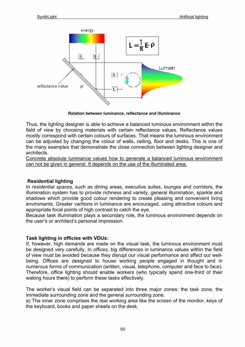
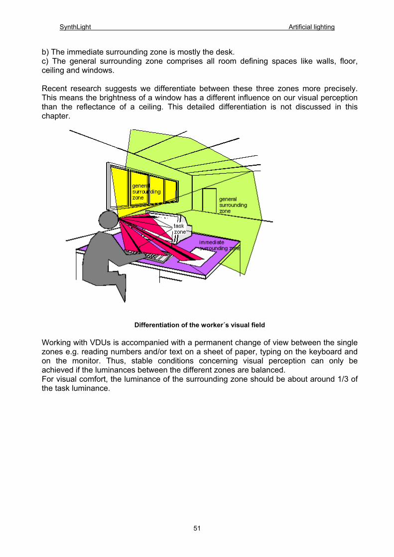
Relation between luminance, reflectance and illuminance Thus, the lighting designer is able to achieve a balanced luminous environment within the field of view by choosing materials with certain reflectance values. Reflectance values mostly correspond with certain colours of surfaces. That means the luminous environment can be adjusted by changing the colour of walls, ceiling, floor and desks. This is one of the many examples that demonstrate the close connection between lighting designer and architects. Concrete absolute luminance values how to generate a balanced luminous environment can not be given in general. It depends on the use of the illuminated area. Residential lighting In residential spaces, such as dining areas, executive suites, lounges and corridors, the illumination system has to provide richness and variety, general illumination, sparkle and shadows which provide good colour rendering to create pleasing and convenient living enviroments. Greater varitions in luminance are encouraged, using attractive colours and appropriate focal points of high contrast to catch the eye. Because task illumination plays a secondary role, the luminous environment depends on the user’s or architect’s personal impression. Task lighting in officies with VDUs: If, however, high demands are made on the visual task, the luminous environment must be designed very carefully. In offices, big differences in luminance values within the field of view must be avoided because they disrupt our visual performance and affect our well-being. Offices are designed to house working people engaged in thought and in numerous forms of communication (written, visual, telephone, computer and face to face). Therefore, office lighting should enable workers (who typically spend one-third of their waking hours there) to perform these tasks effectively. The worker’s visual field can be separated into three major zones: the task zone, the immediate surrounding zone and the general surrounding zone. a) The inner zone comprises the real working area like the screen of the monitor, keys of the keyboard, books and paper sheets on the desk.
50
SynthLight Artificial lighting
b) The immediate surrounding zone is mostly the desk. c) The general surrounding zone comprises all room defining spaces like walls, floor, ceiling and windows. Recent research suggests we differentiate between these three zones more precisely. This means the brightness of a window has a different influence on our visual perception than the reflectance of a ceiling. This detailed differentiation is not discussed in this chapter.
Differentiation of the worker´s visual field
Working with VDUs is accompanied with a permanent change of view between the single zones e.g. reading numbers and/or text on a sheet of paper, typing on the keyboard and on the monitor. Thus, stable conditions concerning visual perception can only be achieved if the luminances between the different zones are balanced. For visual comfort, the luminance of the surrounding zone should be about around 1/3 of the task luminance.
51
SynthLight Artificial lighting
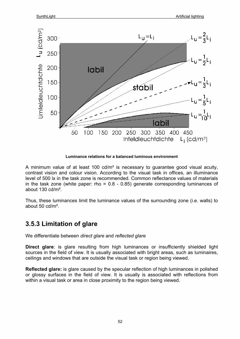
Luminance relations for a balanced luminous environment
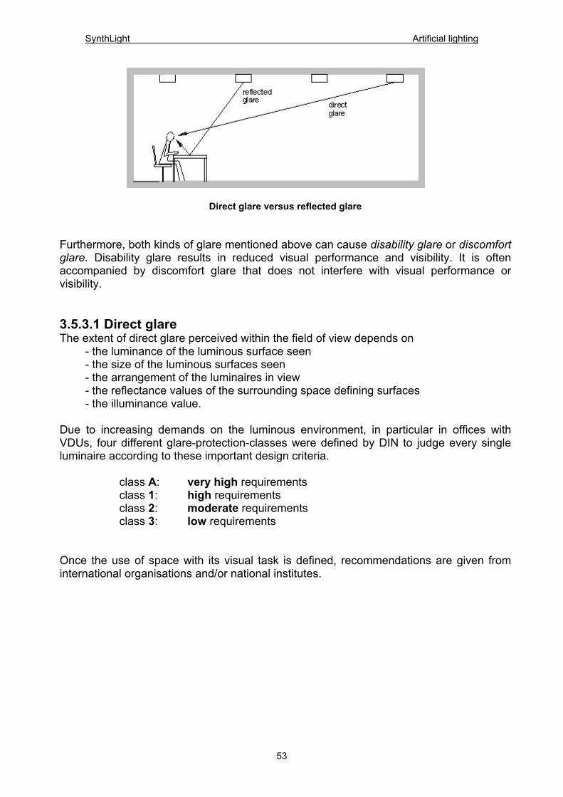
A minimum value of at least 100 cd/m² is necessary to guarantee good visual acuity, contrast vision and colour vision. According to the visual task in offices, an illuminance level of 500 lx in the task zone is recommended. Common reflectance values of materials in the task zone (white paper: rho = 0.8 - 0.85) generate corresponding luminances of about 130 cd/m². Thus, these luminances limit the luminance values of the surrounding zone (i.e. walls) to about 50 cd/m². 3.5.3 Limitation of glare We differentiate between direct glare and reflected glare Direct glare: is glare resulting from high luminances or insufficiently shielded light sources in the field of view. It is usually associated with bright areas, such as luminaires, ceilings and windows that are outside the visual task or region being viewed. Reflected glare: is glare caused by the specular reflection of high luminances in polished or glossy surfaces in the field of view. It is usually is associated with reflections from within a visual task or area in close proximity to the region being viewed.
52
SynthLight Artificial lighting
Direct glare versus reflected glare Furthermore, both kinds of glare mentioned above can cause disability glare or discomfort glare. Disability glare results in reduced visual performance and visibility. It is often accompanied by discomfort glare that does not interfere with visual performance or visibility. 3.5.3.1 Direct glare The extent of direct glare perceived within the field of view depends on - the luminance of the luminous surface seen - the size of the luminous surfaces seen - the arrangement of the luminaires in view - the reflectance values of the surrounding space defining surfaces - the illuminance value. Due to increasing demands on the luminous environment, in particular in offices with VDUs, four different glare-protection-classes were defined by DIN to judge every single luminaire according to these important design criteria.
class A: very high requirements class 1: high requirements class 2: moderate requirements class 3: low requirements Once the use of space with its visual task is defined, recommendations are given from international organisations and/or national institutes.
53
SynthLight Artificial lighting
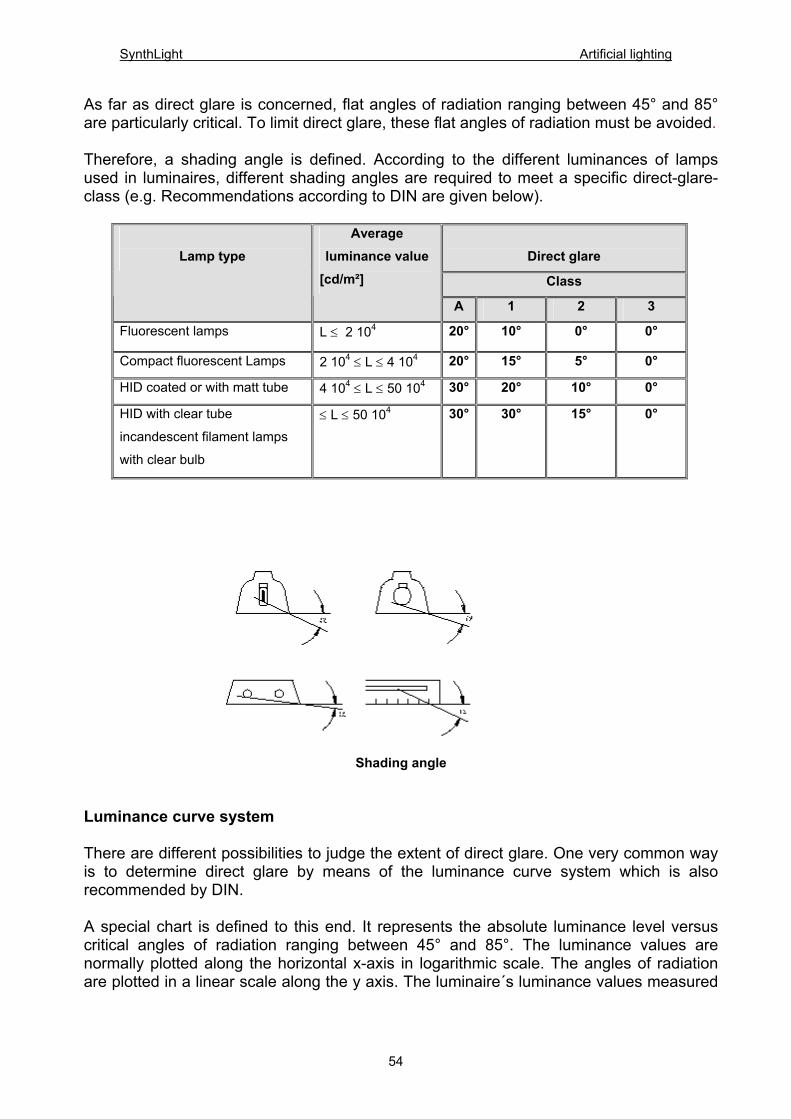
As far as direct glare is concerned, flat angles of radiation ranging between 45° and 85° are particularly critical. To limit direct glare, these flat angles of radiation must be avoided. Therefore, a shading angle is defined. According to the different luminances of lamps used in luminaires, different shading angles are required to meet a specific direct-glare-class (e.g. Recommendations according to DIN are given below).
Direct glare
Class
Lamp type
Average luminance value
[cd/m²]
A 1 2 3
Fluorescent lamps L ≤ 2 104 20° 10° 0° 0°
Compact fluorescent Lamps 2 104 ≤ L ≤ 4 104 20° 15° 5° 0°
HID coated or with matt tube 4 104 ≤ L ≤ 50 104 30° 20° 10° 0°
HID with clear tube
incandescent filament lamps
with clear bulb
≤ L ≤ 50 104 30° 30° 15° 0°
Shading angle Luminance curve system There are different possibilities to judge the extent of direct glare. One very common way is to determine direct glare by means of the luminance curve system which is also recommended by DIN. A special chart is defined to this end. It represents the absolute luminance level versus critical angles of radiation ranging between 45° and 85°. The luminance values are normally plotted along the horizontal x-axis in logarithmic scale. The angles of radiation are plotted in a linear scale along the y axis. The luminaire´s luminance values measured
54
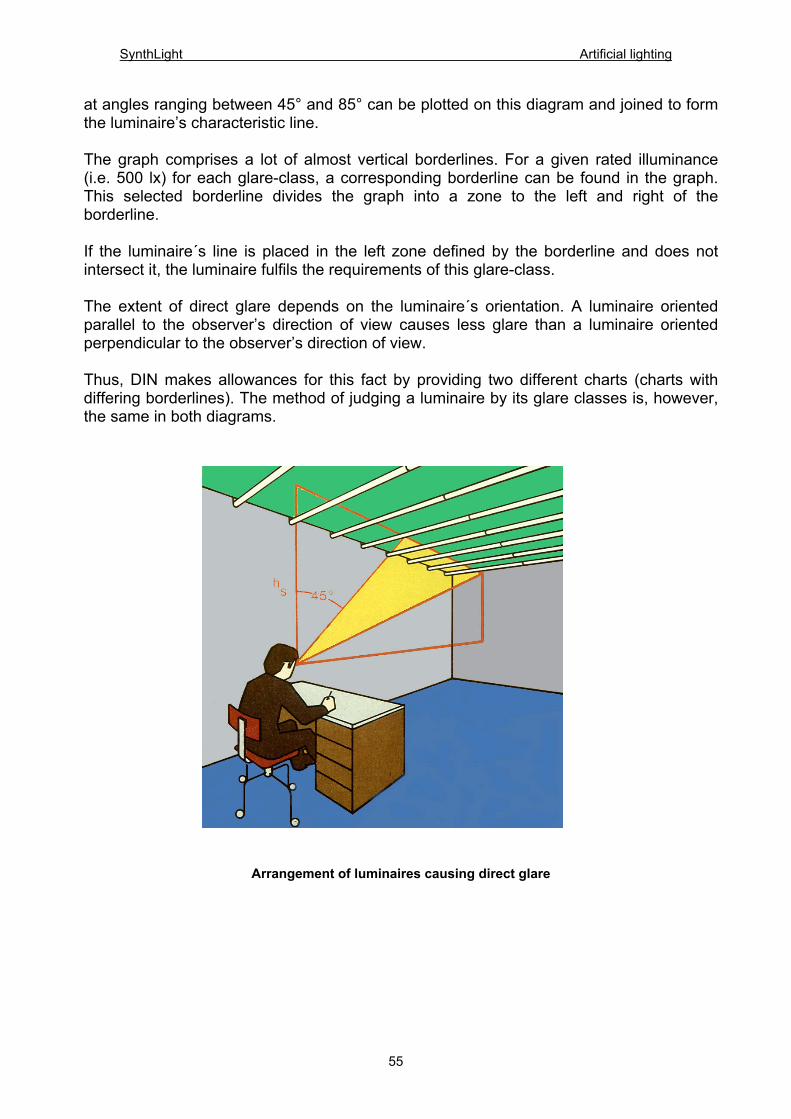
SynthLight Artificial lighting
at angles ranging between 45° and 85° can be plotted on this diagram and joined to form the luminaire’s characteristic line. The graph comprises a lot of almost vertical borderlines. For a given rated illuminance (i.e. 500 lx) for each glare-class, a corresponding borderline can be found in the graph. This selected borderline divides the graph into a zone to the left and right of the borderline. If the luminaire´s line is placed in the left zone defined by the borderline and does not intersect it, the luminaire fulfils the requirements of this glare-class. The extent of direct glare depends on the luminaire´s orientation. A luminaire oriented parallel to the observer’s direction of view causes less glare than a luminaire oriented perpendicular to the observer’s direction of view. Thus, DIN makes allowances for this fact by providing two different charts (charts with differing borderlines). The method of judging a luminaire by its glare classes is, however, the same in both diagrams.
Arrangement of luminaires causing direct glare
55
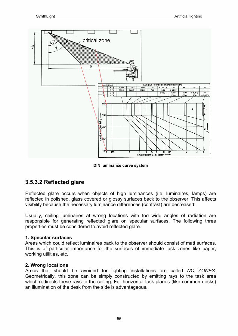
SynthLight Artificial lighting
DIN luminance curve system 3.5.3.2 Reflected glare Reflected glare occurs when objects of high luminances (i.e. luminaires, lamps) are reflected in polished, glass covered or glossy surfaces back to the observer. This affects visibility because the necessary luminance differences (contrast) are decreased. Usually, ceiling luminaires at wrong locations with too wide angles of radiation are responsible for generating reflected glare on specular surfaces. The following three properties must be considered to avoid reflected glare. 1. Specular surfaces Areas which could reflect luminaires back to the observer should consist of matt surfaces. This is of particular importance for the surfaces of immediate task zones like paper, working utilities, etc. 2. Wrong locations Areas that should be avoided for lighting installations are called NO ZONES. Geometrically, this zone can be simply constructed by emitting rays to the task area which redirects these rays to the ceiling. For horizontal task planes (like common desks) an illumination of the desk from the side is advantageous.
56
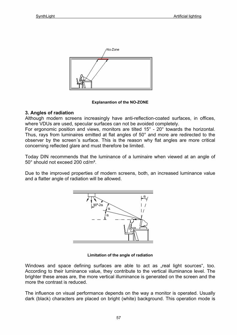
SynthLight Artificial lighting
Explanantion of the NO-ZONE 3. Angles of radiation Although modern screens increasingly have anti-reflection-coated surfaces, in offices, where VDUs are used, specular surfaces can not be avoided completely. For ergonomic position and views, monitors are tilted 15° - 20° towards the horizontal. Thus, rays from luminaires emitted at flat angles of 50° and more are redirected to the observer by the screen´s surface. This is the reason why flat angles are more critical concerning reflected glare and must therefore be limited. Today DIN recommends that the luminance of a luminaire when viewed at an angle of 50° should not exceed 200 cd/m². Due to the improved properties of modern screens, both, an increased luminance value and a flatter angle of radiation will be allowed.
Limitation of the angle of radiation Windows and space defining surfaces are able to act as „real light sources“, too. According to their luminance value, they contribute to the vertical illuminance level. The brighter these areas are, the more vertical illuminance is generated on the screen and the more the contrast is reduced. The influence on visual performance depends on the way a monitor is operated. Usually dark (black) characters are placed on bright (white) background. This operation mode is
57
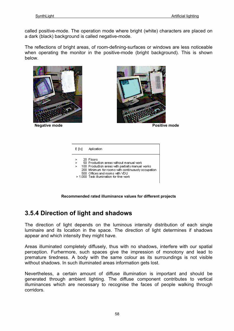
SynthLight Artificial lighting
called positive-mode. The operation mode where bright (white) characters are placed on a dark (black) background is called negative-mode. The reflections of bright areas, of room-defining-surfaces or windows are less noticeable when operating the monitor in the positive-mode (bright background). This is shown below.
Negative mode Positive mode
Recommended rated illuminance values for different projects
3.5.4 Direction of light and shadows The direction of light depends on the luminous intensity distribution of each single luminaire and its location in the space. The direction of light determines if shadows appear and which intensity they might have. Areas illuminated completely diffusely, thus with no shadows, interfere with our spatial perception. Furhermore, such spaces give the impression of monotony and lead to premature tiredness. A body with the same colour as its surroundings is not visible without shadows. In such illuminated areas information gets lost. Nevertheless, a certain amount of diffuse illumination is important and should be generated through ambient lighting. The diffuse component contributes to vertical illuminances which are necessary to recognise the faces of people walking through corridors.
58
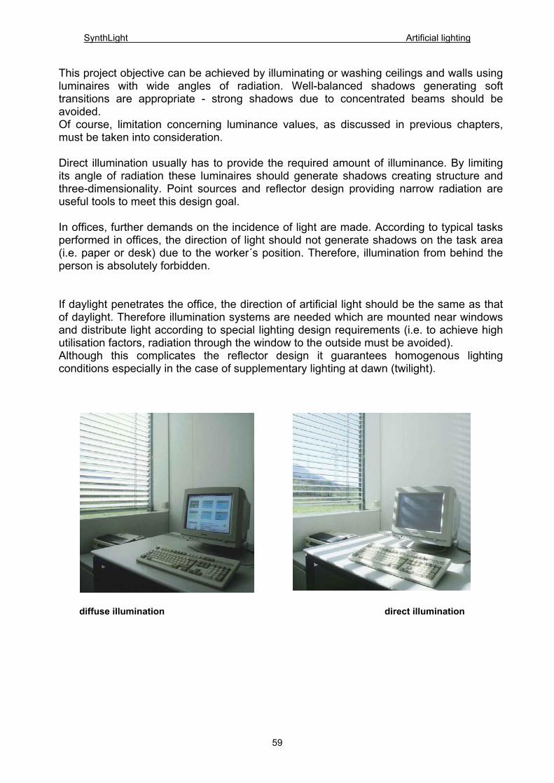
SynthLight Artificial lighting
This project objective can be achieved by illuminating or washing ceilings and walls using luminaires with wide angles of radiation. Well-balanced shadows generating soft transitions are appropriate - strong shadows due to concentrated beams should be avoided. Of course, limitation concerning luminance values, as discussed in previous chapters, must be taken into consideration. Direct illumination usually has to provide the required amount of illuminance. By limiting its angle of radiation these luminaires should generate shadows creating structure and three-dimensionality. Point sources and reflector design providing narrow radiation are useful tools to meet this design goal. In offices, further demands on the incidence of light are made. According to typical tasks performed in offices, the direction of light should not generate shadows on the task area (i.e. paper or desk) due to the worker´s position. Therefore, illumination from behind the person is absolutely forbidden. If daylight penetrates the office, the direction of artificial light should be the same as that of daylight. Therefore illumination systems are needed which are mounted near windows and distribute light according to special lighting design requirements (i.e. to achieve high utilisation factors, radiation through the window to the outside must be avoided). Although this complicates the reflector design it guarantees homogenous lighting conditions especially in the case of supplementary lighting at dawn (twilight).
diffuse illumination direct illumination
59
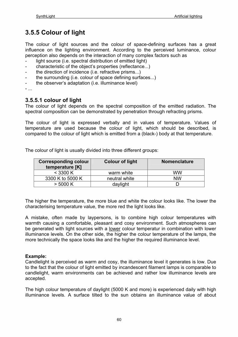
SynthLight Artificial lighting
3.5.5 Colour of light
The colour of light sources and the colour of space-defining surfaces has a great influence on the lighting environment. According to the perceived luminance, colour perception also depends on the interaction of many complex factors such as - light source (i.e. spectral distribution of emitted light) - characteristic of the object’s properties (reflectance...) - the direction of incidence (i.e. refractive prisms...) - the surrounding (i.e. colour of space defining surfaces...) - the observer’s adaptation (i.e. illuminance level) - ... 3.5.5.1 colour of light The colour of light depends on the spectral composition of the emitted radiation. The spectral composition can be demonstrated by penetration through refracting prisms. The colour of light is expressed verbally and in values of temperature. Values of temperature are used because the colour of light, which should be described, is compared to the colour of light which is emitted from a (black-) body at that temperature. The colour of light is usually divided into three different groups:
Corresponding colour temperature [K]
Colour of light Nomenclature
< 3300 K warm white WW 3300 K to 5000 K neutral white NW
> 5000 K daylight D The higher the temperature, the more blue and white the colour looks like. The lower the characterising temperature value, the more red the light looks like. A mistake, often made by laypersons, is to combine high colour temperatures with warmth causing a comfortable, pleasant and cosy environment. Such atmospheres can be generated with light sources with a lower colour temperatur in combination with lower illuminance levels. On the other side, the higher the colour temperature of the lamps, the more technically the space looks like and the higher the required illuminance level. Example: Candlelight is perceived as warm and cosy, the illuminance level it generates is low. Due to the fact that the colour of light emitted by incandescent filament lamps is comparable to candlelight, warm environments can be achieved and rather low illuminance levels are accepted. The high colour temperature of daylight (5000 K and more) is experienced daily with high illuminance levels. A surface tilted to the sun obtains an illuminance value of about
60
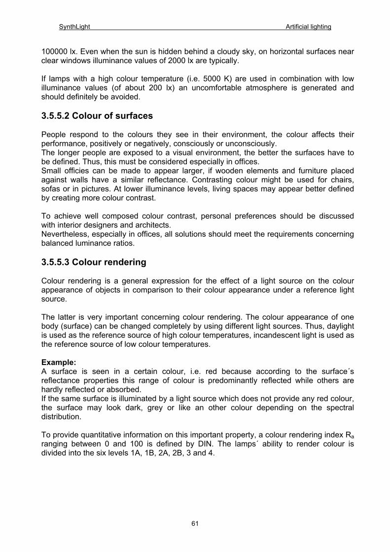
SynthLight Artificial lighting
100000 lx. Even when the sun is hidden behind a cloudy sky, on horizontal surfaces near clear windows illuminance values of 2000 lx are typically. If lamps with a high colour temperature (i.e. 5000 K) are used in combination with low illuminance values (of about 200 lx) an uncomfortable atmosphere is generated and should definitely be avoided. 3.5.5.2 Colour of surfaces People respond to the colours they see in their environment, the colour affects their performance, positively or negatively, consciously or unconsciously. The longer people are exposed to a visual environment, the better the surfaces have to be defined. Thus, this must be considered especially in offices. Small officies can be made to appear larger, if wooden elements and furniture placed against walls have a similar reflectance. Contrasting colour might be used for chairs, sofas or in pictures. At lower illuminance levels, living spaces may appear better defined by creating more colour contrast. To achieve well composed colour contrast, personal preferences should be discussed with interior designers and architects. Nevertheless, especially in offices, all solutions should meet the requirements concerning balanced luminance ratios. 3.5.5.3 Colour rendering Colour rendering is a general expression for the effect of a light source on the colour appearance of objects in comparison to their colour appearance under a reference light source. The latter is very important concerning colour rendering. The colour appearance of one body (surface) can be changed completely by using different light sources. Thus, daylight is used as the reference source of high colour temperatures, incandescent light is used as the reference source of low colour temperatures. Example: A surface is seen in a certain colour, i.e. red because according to the surface´s reflectance properties this range of colour is predominantly reflected while others are hardly reflected or absorbed. If the same surface is illuminated by a light source which does not provide any red colour, the surface may look dark, grey or like an other colour depending on the spectral distribution.
To provide quantitative information on this important property, a colour rendering index Ra ranging between 0 and 100 is defined by DIN. The lamps´ ability to render colour is divided into the six levels 1A, 1B, 2A, 2B, 3 and 4.
61
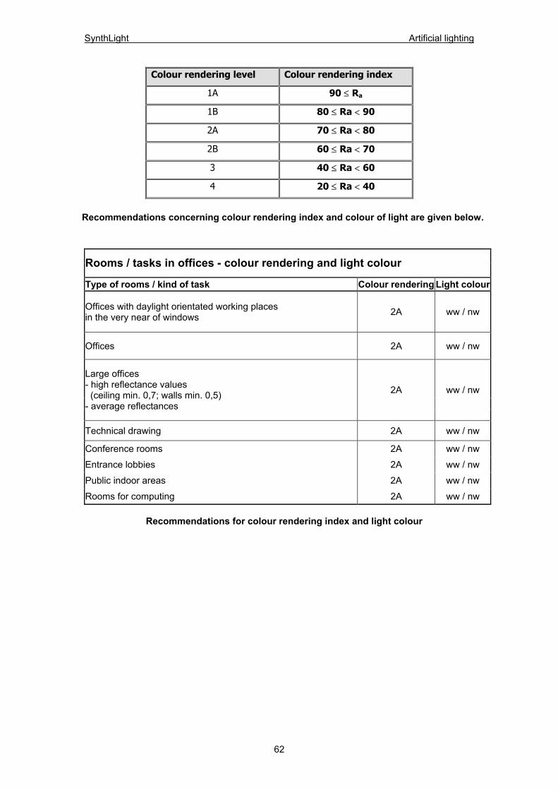
SynthLight Artificial lighting
Colour rendering level Colour rendering index
1A 90 ≤ Ra
1B 80 ≤ Ra < 90
2A 70 ≤ Ra < 80
2B 60 ≤ Ra < 70
3 40 ≤ Ra < 60
4 20 ≤ Ra < 40
Recommendations concerning colour rendering index and colour of light are given below.
Rooms / tasks in offices - colour rendering and light colour
Type of rooms / kind of task Colour rendering Light colour
Offices with daylight orientated working places in the very near of windows 2A ww / nw
Offices 2A ww / nw
Large offices - high reflectance values (ceiling min. 0,7; walls min. 0,5) - average reflectances
2A ww / nw
Technical drawing 2A ww / nw
Conference rooms 2A ww / nw
Entrance lobbies 2A ww / nw
Public indoor areas 2A ww / nw
Rooms for computing 2A ww / nw
Recommendations for colour rendering index and light colour
62
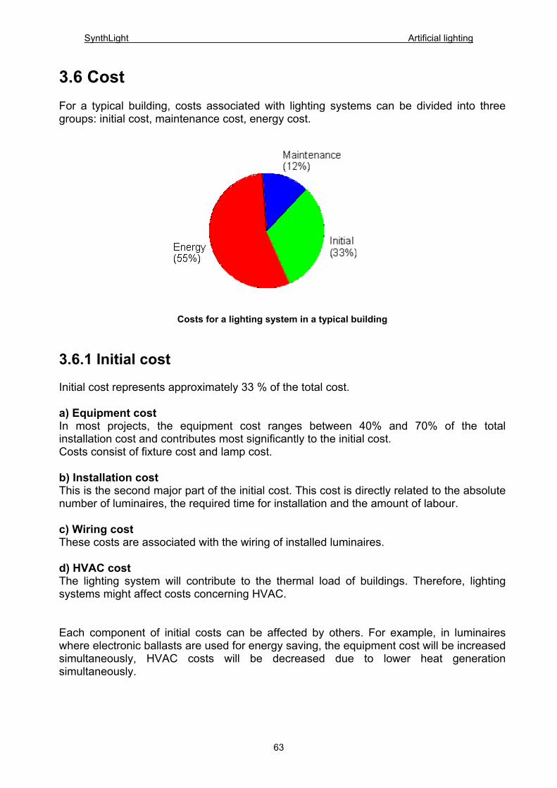
SynthLight Artificial lighting
3.6 Cost For a typical building, costs associated with lighting systems can be divided into three groups: initial cost, maintenance cost, energy cost.
Costs for a lighting system in a typical building
3.6.1 Initial cost Initial cost represents approximately 33 % of the total cost. a) Equipment cost In most projects, the equipment cost ranges between 40% and 70% of the total installation cost and contributes most significantly to the initial cost. Costs consist of fixture cost and lamp cost. b) Installation cost This is the second major part of the initial cost. This cost is directly related to the absolute number of luminaires, the required time for installation and the amount of labour. c) Wiring cost These costs are associated with the wiring of installed luminaires. d) HVAC cost The lighting system will contribute to the thermal load of buildings. Therefore, lighting systems might affect costs concerning HVAC. Each component of initial costs can be affected by others. For example, in luminaires where electronic ballasts are used for energy saving, the equipment cost will be increased simultaneously, HVAC costs will be decreased due to lower heat generation simultaneously.
63

SynthLight Artificial lighting
3.6.2 Maintenance cost Maintenance cost represents approximately 12% of the total cost. a) Relamping The costs that are associated with relamping depend on the time period after which the exchange of lamps is necessary. According to the different lamp types, lamp life and the luminaire ’s accessibility, special maintenance schedules are recommended. These suggest either spot relamping (replacing each individual lamp as it burns out) or group relamping (replacing all lamps whether they have burned out or not). Especially in large facilities, the latter method becomes much more efficient and requires less time. Despite that, the negative effects on aesthetics and safety due to having luminaires with extinguished lamps must be considered. b) Reballasting The cost due to reballasting becomes more important the longer the lighting system is used. If this period lasts less than 25 years, this cost component becomes insignificant. c) Cleaning Cleaning costs correspond to the time, which is needed to do this task. This work can be done efficiently during phases of relamping. If luminaires are located in environments with higher exposure to dust, they may also be cleaned more frequently. d) Others Miscellaneous maintenance costs are incurred if parts of the luminaire i.e. cover glasses or snappers must be replaced. To complete the economic calculations, insurance costs can be mentioned. They do not contribute significantly to the maintenance cost. 3.6.3 Energy cost Energy cost represents approximately 55% of the total cost. As shown in the diagram above, the cost of supplying enough electrical energy to the lighting system is the most significant cost factor of lighting economics. Energy cost is incurred by the connected lighting energy load, the cost of energy and the annual operating hours of the lighting system.
64
SynthLight Artificial lighting
3.7 References 3.7.1 Publications 1. Manfred Richter, ‘’Einführung in die Farbmetrik“, Walter de Gruyter, 1981 2. Bruno Weis, „Industriebeleuchtung“, Pflaum Verlag, 2000 3. Bruno Weis, „Beleuchtungstechnik“, Pflaum Verlag, 1996 4. Hans-Jürgen Hentschel, „Licht und Beleuchtung“, Hüthig Verlag, 2002 5. Trilux, „Beleuchtungsplanung – Lichttechnik, Elektrotechnik“, Trilux Lenze GmbH, Arnsberg, 1997 6. H.A.E Keitz, „Lichtberechnungen und Lichtmessungen“, Philips Technische Bibliothek, 1967 7. Horst Lange, „Handbuch für Beleuchtung“, ecomed, 1998 8. Fördergemeinschaft Gutes Licht, Schriftenreihe „Gutes Licht“ 9. Mark S. Rea, „Lighting Handbook“, Illuminating Engineering Society of North America, 1993 10. J. Hesse, T. Müller, K. Stolzenberg, „Blendungsbewertungsverfahren und UGR-System“, Wirtschaftsverlag NW, 1998 11. Deutsche Lichttechnische Gesellschaft, „Messung und Beurteilung von Lichtimmissionen künstlicher Lichtquellen“, 1996 12. International commission on illumination, „Discomfort glare in interior lighting“, 1995 13. International commission on illumination, „CIE collection on glare“, 2002 14. Dr. Walter Witting, „Visuelle Belastung bei Bildschirmarbeit“, Bartenbach Lichtlabor
3.7.2 Catalogues 1. Osram, „Light programme", actual version 2002/2003 2. Philips, General OEM catalogue Lamps & Gear/Control, 2003/2004
3.7.3 Journals 1. „Licht“, Pflaum Verlag
3.7.4 Web sites for LED http://www.led-info.de/ http://www.lumileds.com/ http://www.nichia.com/ http://www.osram-os.com/products/led.html http://www.radimg.com/ref_publications.htm http://www.tridonic.at/toe/ http://www.lrc.rpi.edu/programs/solidstate/ http://www.semiconductor.agilent.com/ http://www.labsphere.com/tech_info/default.asp?Show=TechPub http://lighting.sandia.gov/
65