Zg-3 Zero Gauss Chambers - EMI Electromagnetic Interference Shielding

Chapter 23Gauss’ Law
1

1. Introduction
Evaluating the electric field of a charge distribution is usually difficult.
If a certain charge distribution is symmetric enough, we then can easily find theelectric field with the help of Gauss’ law.
Gauss’ law considers an imaginary closed surface enclosing a charge distribution,called the Gaussian surface. The Gaussian surface mimics the symmetry of thecharge distribution. For example, if the charge distribution is spherical, we enclosethe charge with a spherical Gaussian surface.
Gauss’ law relates the electric fields at points on a (closed) Gaussian surface to thenet charge enclosed by that surface.
2

1. Introduction
We can also use Gauss’ law in reverse. If we know the electric field on a Gaussiansurface, we can find the net charge enclosed by the surface.
To know how much charge is enclosed, we first need to know how much electricfield is intercepted by the Gaussian surface.
A measure of intercepted field is called the flux.
3

2. Flux of an Electric Field
The electric flux Φ through a surface is theamount of electric field that pierces the surface.
The area vector 𝑑 𝐴 for an area element (patchelement) on a surface is a vector that isperpendicular to the element and has amagnitude equal to the area 𝑑𝐴 of the element.
The electric flux 𝑑Φ through a patch elementwith area vector 𝑑 𝐴 is given by
𝑑Φ = 𝐸 cos 𝜃 𝑑𝐴.
4

2. Flux of an Electric Field
We can rewrite the last expression as a dotproduct:
𝑑Φ = 𝐸 ∙ 𝑑 𝐴.
The total flux through a surface is given by
Φ = 𝐸 ∙ 𝑑 𝐴 ,
where the integration is carried over the surface.
The flux of the electric field is a scalar. Its SI unitis N ∙ m2/C.
5

2. Flux of an Electric Field
Consider the closed Gaussian surface shown in thefigure. An inward piercing field is negative flux. Anoutward piercing field is positive flux. A skimming field iszero flux.
The net flux of the electric field through the surface is
Φ = 𝐸 ∙ ∆ 𝐴.
In the limit that ∆ 𝐴 → 𝑑 𝐴 we get that
Φ = 𝐸 ∙ 𝑑 𝐴 .
6

2. Flux of an Electric Field
Recall that the magnitude of the electric field isproportional to the number of electric field lines perunit area. Thus, the flux is proportional to the numberof electric field lines passing through area 𝑑 𝐴.
We can therefore interpret the electric flux as follows:
The electric flux Φ through a Gaussian surface isproportional to the net number of electric field linespassing through that surface.
7

2. Flux of an Electric Field
8
(a) 𝐸𝐴
(b) −𝐸𝐴
(c) 0
(d) 0

3. Flux of an Electric Field
Example 1: the figure shows a Gaussian surfacein the form of a cylinder of radius R immersed ina uniform electric field, with the cylinder axisparallel to the field. What is the flux Φ of theelectric field through this closed surface?
We can do the integration by writing the flux asthe sum of three terms: the integrals over theleft cylinder cap 𝑎, the cylindrical surface 𝑏, andthe right cap 𝑐.
9
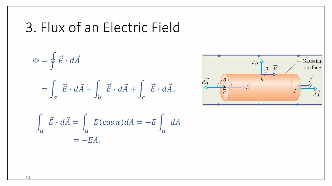
3. Flux of an Electric Field
Φ = 𝐸 ∙ 𝑑 𝐴
= 𝑎
𝐸 ∙ 𝑑 𝐴 + 𝑏
𝐸 ∙ 𝑑 𝐴 + 𝑐
𝐸 ∙ 𝑑 𝐴 .
𝑎
𝐸 ∙ 𝑑 𝐴 = 𝑎
𝐸 cos 𝜋 𝑑𝐴 = −𝐸 𝑎
𝑑𝐴
= −𝐸𝐴.
10

3. Flux of an Electric Field
𝑏
𝐸 ∙ 𝑑 𝐴 = 𝑏
𝐸 cos 𝜋/2 𝑑𝐴 = 0.
𝑐
𝐸 ∙ 𝑑 𝐴 = 𝑐
𝐸 cos 0 𝑑𝐴 = 𝐸 𝑐
𝑑𝐴
= 𝐸𝐴.
Thus,
Φ = −𝐸𝐴 + 0 + 𝐸𝐴 = 0.
11
3. Flux of an Electric Field
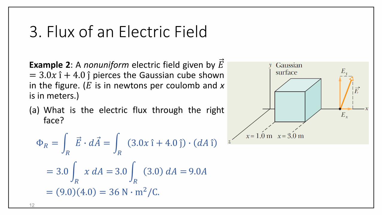
Example 2: A nonuniform electric field given by 𝐸= 3.0𝑥 i + 4.0 j pierces the Gaussian cube shownin the figure. (𝐸 is in newtons per coulomb and xis in meters.)
(a) What is the electric flux through the rightface?
Φ𝑅 = 𝑅
𝐸 ∙ 𝑑 𝐴 = 𝑅
3.0𝑥 i + 4.0 j ∙ 𝑑𝐴 i
= 3.0 𝑅
𝑥 𝑑𝐴 = 3.0 𝑅
3.0 𝑑𝐴 = 9.0𝐴
= 9.0 4.0 = 36 N ∙ m2/C.12

3. Flux of an Electric Field
(b) What is the electric flux through the left face?
Φ𝐿 = 𝐿
𝐸 ∙ 𝑑 𝐴 = 𝐿
3.0𝑥 i + 4.0 j ∙ −𝑑𝐴 i
= −3.0 𝐿
𝑥 𝑑𝐴 = − 3.0 𝐿
1.0 𝑑𝐴
= −3.0𝐴 = − 3.0 4.0
= −12 N ∙ m2/C.
13

3. Flux of an Electric Field
(c) What is the electric flux through the top face?
Φ𝑇 = 𝑇
𝐸 ∙ 𝑑 𝐴 = 𝑇
3.0𝑥 i + 4.0 j ∙ 𝑑𝐴 J
= 4.0 𝑇
𝑑𝐴 = 4.0𝐴 = 4.0 4.0
= 16 N ∙ m2/C.
14

4. Gauss’ Law
Gauss’ law relates the net flux Φ of an electric field through a closed surface (aGaussian surface) to the net charge 𝑞enc that is enclosed by that surface:
Φ =𝑞enc
𝜀0.
Using the expression for Φ we get
𝐸 ∙ 𝑑 𝐴 =𝑞enc
𝜀0.
15

4. Gauss’ Law
Let us apply Gauss’ law to the charge(s) shown in thefigure.
Surface 𝑆1: The electric field lines point outward for allpoints on the surface. The flux is thus positive and so is thenet charge within the surface (If Φ is positive, 𝑞enc mustbe positive too).
Surface 𝑆2: The electric field lines point inward for allpoints on the surface. The flux is thus negative and so isthe net charge within the surface.
Surface 𝑆3: The electric field lines pass entirely throughthe surface. The flux is thus zero. This surface encloses nocharge and thus 𝑞enc = 0. Gauss’ law too requires that thenet flux is zero.
16

4. Gauss’ Law
Surface 𝑆4: This surface encloses zero net charge. Gauss’law requires that the net flux of the electric field throughthis surface is zero. There are as many field lines leavingthe surface as entering it.
Q: What happens if we were to bring charge 𝑄 up close to𝑆4?
A: The pattern of the electric field lines would change, butthe net flux for each of the four Gaussian surface wouldnot change. The field lines associated with the addedcharge 𝑄 would pass entirely through each of the foursurfaces. 𝑄 would not enter Gauss’ law since 𝑄 lies outsideall four Gaussian surfaces.
17
𝑸

4. Gauss’ Law
18
(a) 2
(b) 3
(c) 1

4. Gauss’ Law
Example 3: The figure shows five charged lumpsof plastic and an electrically neutral coin. Thecross section of a Gaussian surface 𝑆 is indicated.What is the net electric flux through the surface if𝑞1 = 𝑞4 = +3.1 nC 𝑞2 = 𝑞5 = −5.9 nC, and 𝑞3= −3.1 nC?
Φ =𝑞enc
𝜀0=
𝑞1 + 𝑞2 + 𝑞3
𝜀0
=3.1 nC − 5.9 nC − 3.1 nC
8.85 × 10⁻¹² C2/N ∙ m2
= −670 N ∙ m2/C.
19

5. Gauss’ Law and Coulomb’s Law
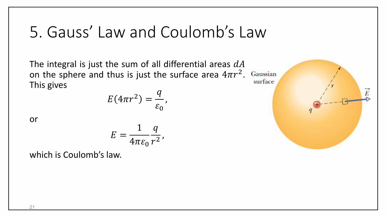
Here we want to derive Coulomb’s law from Gauss’law. For the Gaussian surface in the figure
𝐸 ∙ 𝑑 𝐴 = 𝐸𝑑𝐴 cos 0 = 𝐸𝑑𝐴 =𝑞enc
𝜀0=
𝑞
𝜀0.
𝐸 is constant over the surface and we can take it out ofthe integral:
𝐸 𝑑𝐴 =𝑞
𝜀0.
20
5. Gauss’ Law and Coulomb’s Law
The integral is just the sum of all differential areas 𝑑𝐴on the sphere and thus is just the surface area 4𝜋𝑟2.This gives
𝐸 4𝜋𝑟2 =𝑞
𝜀0,
or
𝐸 =1
4𝜋𝜀0
𝑞
𝑟2,
which is Coulomb’s law.
21

5. Gauss’ Law and Coulomb’s Law
22
(a) Equal to Φ𝑖.
(b) Equal to Φ𝑖.
(c) Equal to Φ𝑖.Φ =
𝑞
𝜀0

6. A Charged Isolated Conductor
Gauss’ law can be used to prove an important theorem about conductors:
“If an excess charge is placed on an isolated conductor, that amount of charge willmove entirely to the surface of the conductor. None of the excess charge will befound within the body of the conductor.”
This sounds reasonable because charges with the same sign repel one another andget as far away from one another as they can.
Let us use Gauss’ law to prove this speculation.
23

6. A Charged Isolated Conductor
The figure shows an isolated copper lump having anexcess charges 𝑞. We place a Gaussian surface justinside the surface of the conductor.
The electric field inside this conductor must be zero. Ifthis were not so, the field would move the conductionelectrons, generating a continuous current. Since thereis no such current in isolated conductors, the fieldinside is zero.
The electric field is zero for all points on the Gaussiansurface. The flux through the Gaussian surface must bezero too. The excess charge is not inside the Gaussiansurface, it must lie on the surface of the conductor.
24

6. A Charged Isolated Conductor
An Isolated Conductor with a Cavity
Consider the previous figure but now with a cavity that istotally within the conductor. It is reasonable to say thatwhen we scoop out the electrically neutral material toform the cavity we do not change the charge distribution.Let us prove this conclusion quantitatively using Gauss’law.
We draw a Gaussian surface surrounding the cavity.Because 𝐸 = 0 inside the conductor, the flux through thisGaussian surface is zero. We conclude that the net chargeon the cavity walls is zero. All the excess charge remainson the outer surface of the conductor.
25

6. A Charged Isolated Conductor
The Conductor Removed
Suppose that we remove the conductor completely and leave only the charges. Theelectric field would not change and would remain zero inside this thin shell andwould remain unchanged for all external points. The electric field is set upcompletely by the charges and not by the conductors.
26

6. A Charged Isolated Conductor
The External Electric Field
We have seen that excess charge on an isolatedconductor move entirely to the surface. The chargedistribution (or the charge density 𝜎 = 𝑞/𝐴 ) isuniform only when the conductor is spherical.Generally, this nonuniformity makes thedetermination of the electric field set up by thesurface charge very difficult.
Luckily, we can determine the electric field justoutside the surface easily using Gauss’ law. Considerthe Gaussian surface shown in the figure.
27

6. A Charged Isolated Conductor
The External Electric Field
The electric field 𝐸 at and just outside the conductorsurface must be perpendicular to the conductorsurface. Otherwise, the electric field would have acomponent along the conductor surface, causing thecharges to move.
The flux through the internal cap of the Gaussiansurface is zero since there is no field inside theconductor. The flux through the curved surface ofthe cylinder is zero too because the electric field isparallel to the curved surface.
28

6. A Charged Isolated Conductor
The External Electric Field
We assume that the cap is small enough that theelectric is constant over the outer cap. The fluxthough the cap is then 𝐸𝐴.
The charge 𝑞enc enclosed by the Gaussian surface is𝜎𝐴, where 𝜎 is the charge per unit area. Gauss’ lawbecomes
𝐸𝐴 =𝜎𝐴
𝜀0,
or
𝐸 =𝜎
𝜀0.
29

6. A Charged Isolated Conductor
Example 4: The figure shows a cross section of aspherical metal shell of inner radius 𝑅. A point chargeof −5.0 𝜇C is located at a distance 𝑅/2 from thecenter of the shell. If the shell is electrically neutral,what are the (induced) charges on its inner and outersurfaces? Are those charges uniformly distributed?
30

6. A Charged Isolated Conductor
The electric field must be zero inside the metal. Thismakes the flux through the Gaussian surface shownin the figure zero.
With a point charge of −5.0 𝜇C within the shell, acharge of +5.0 𝜇C must lie on the inner wall of theshell in order that the net enclosed charge be zero.This positive charge is not uniformly distributed.
The induced charge on the outer surface must be− 5.0 𝜇C . This distribution of negative charge isuniform because the shell is spherical and becausethe skewed distribution of positive charge on theinner wall cannot produce an electric field in the shellto affect the distribution of charge on the outer wall.31

6. A Charged Isolated Conductor
What is the field pattern inside and outside the shell?
The field lines inside and outside the shell are shownapproximately in the figure. All the field linesintersect the shell and the point chargeperpendicularly. Inside the shell the pattern of fieldlines is skewed because of the skew of the positivecharge distribution. Outside the shell the pattern isthe same as if the point charge were centered andthe shell were missing.
32

7. Applying Gauss’ Law: Cylindrical Symmetry
The figure shows a section of an infinitely longcylindrical plastic rod with linear charge density 𝜆.We want to find an expression for the electric field 𝐸at a distance 𝑟 from the axis of the rod.
We choose a cylindrical Gaussian surface of radius 𝑟and length ℎ, coaxial with the rod. The symmetry ofthe problem implies that 𝐸 has the same magnitudeat every point on the Gaussian surface, and thedirection of 𝐸 is radially outward for positive 𝜆.
33

7. Applying Gauss’ Law: Cylindrical Symmetry
The flux of 𝐸 through the Gaussian surface is
Φ = 𝐸𝐴 cos 𝜃 = 𝐸 2𝜋𝑟ℎ cos 0 = 𝐸 2𝜋𝑟ℎ .
The charge enclosed by the Gaussian surface is 𝜆ℎ.Gauss’ law becomes
𝐸 2𝜋𝑟ℎ =𝜆ℎ
𝜀0,
yielding
𝐸 =𝜆
2𝜋𝜀0𝑟.
Note that the electric field here is proportional to 1/𝑟!
34

7. Applying Gauss’ Law: Cylindrical Symmetry
Example 5: The figure shows a narrow verticalcylinder of height 𝐿 = 1.8 m and radius 𝑅 = 0.10 m.Assume that charge 𝑄 is uniformly distributed along athin wire along the cylinder’s axis. What value of 𝑄would have put the air at the cylinder’s surface tohave electric field 𝐸𝑐 = 2.4 MN/C?
Because 𝑅 ≪ 𝐿 , we can approximate the chargedistribution as a long line of charge. Thus, for pointsthat are not too near the ends (compared with 𝑅),
𝐸 =𝜆
2𝜋𝜀0𝑅=
𝑄/𝐿
2𝜋𝜀0𝑅.
35

7. Applying Gauss’ Law: Cylindrical Symmetry
Solving for 𝑄 and substituting gives
𝑄 = 2𝜋𝜀0𝑅𝐿𝐸 = 2𝜋𝜀0𝑅𝐿𝐸𝑐
= 2𝜋 8.85 × 10⁻¹² C2/N ∙ m2
× 0.10 m 1.8 m 2.4 MN/C
= 24 𝜇C.
36

8. Applying Gauss’ Law: Planar Symmetry
Nonconducting Sheet:
The figure shows a portion of a thin infinite,nonconducting sheet with a uniform (positive)surface charge density 𝜎. We want to find theelectric field 𝐸 a distance 𝑟 in front of the sheet.
A Gaussian surface is shown. From the symmetryof the problem, 𝐸 must be perpendicular to thesheet, directed away from the surface.
37

8. Applying Gauss’ Law: Planar Symmetry
Nonconducting Sheet:
The flux through each of the end caps of theGaussian surface is 𝐸𝐴. Gauss’ law reads
𝐸𝐴 + 𝐸𝐴 =𝜎𝐴
𝜀0,
or
𝐸 =𝜎
2𝜀0.
The electric field is independent of the distance tothe sheet!
38

8. Applying Gauss’ Law: Planar Symmetry
Two Conducting Plates:
Consider the conducting plate shown in the figure.The magnitude of the electric field outside theplate is 𝐸 = 𝜎1/𝜀0. It points away from the plane.
39

8. Applying Gauss’ Law: Planar Symmetry
Two Conducting Plates:
The electric field has the same magnitude whenthe charge density is negative. The electric fieldpoints toward the plate.
40

8. Applying Gauss’ Law: Planar Symmetry
Two Conducting Plates:
When the two plates are brought neareach other, all the excess charge moveonto the inner faces of the plates, as in thefigure. The electric field at any pointbetween the plates becomes
𝐸 =2𝜎1
𝜀0=
𝜎
𝜀0.
The electric field is directed away from thepositive plate, toward the negative plate.The electric field is zero to the left andright of the plates.
41

8. Applying Gauss’ Law: Planar Symmetry
Example 6: The figure shows portions of two large,parallel, nonconducting sheets, each with a fixeduniform charge. The magnitudes of the surfacecharge densities are 𝜎 + = 6.8 𝜇C/m2 for thepositively charged sheet and 𝜎 − = 4.3 𝜇C/m2 forthe negatively charged sheet.
Find the electric field 𝐸 (a) to the left of the sheets,(b) between the sheets, and (c) to the right of thesheets.
We first calculate the electric field due to each sheetand then use the superposition principle to find thenet electric field 𝐸.
42

8. Applying Gauss’ Law: Planar Symmetry
The electric field field 𝐸 + due to the positive sheet isdirected away from the sheet and has the magnitude
𝐸 + =𝜎 +
2𝜀0=
6.8 × 10⁻⁶ C/m2
(2)8.85 × 10⁻¹² C2/N ∙ m2
= 3.84 × 10⁵N/C.
The electric field field 𝐸 − due to the negative sheetis directed toward the sheet and has the magnitude
𝐸 − =𝜎 −
2𝜀0=
4.3 × 10⁻⁶ C/m2
(2)8.85 × 10⁻¹² C2/N ∙ m2
= 2.43 × 10⁵N/C.
43

8. Applying Gauss’ Law: Planar Symmetry
The magnitude of the net field 𝐸𝐵 between the sheetsis
𝐸𝐵 = 𝐸 + + 𝐸 −
= 3.84 × 10⁵ N/C + 2.43 × 10⁵ N/C
= 6.3 × 10⁵ N/C.
The magnitudes of the left and right net fields 𝐸𝐿 and𝐸𝑅 are
𝐸𝐿 = 𝐸𝑅 = 𝐸 + − 𝐸 −
= 3.84 × 10⁵N/C − 2.43 × 10⁵ N/C
= 1.4 × 10⁵ N/C.44
9. Applying Gauss’ Law: Spherical Symmetry
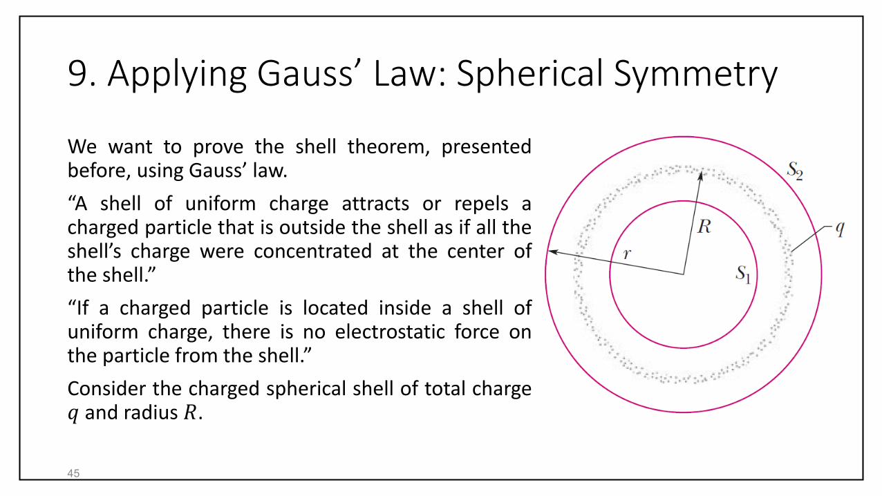
We want to prove the shell theorem, presentedbefore, using Gauss’ law.
“A shell of uniform charge attracts or repels acharged particle that is outside the shell as if all theshell’s charge were concentrated at the center ofthe shell.”
“If a charged particle is located inside a shell ofuniform charge, there is no electrostatic force onthe particle from the shell.”
Consider the charged spherical shell of total charge𝑞 and radius 𝑅.
45

9. Applying Gauss’ Law: Spherical Symmetry
Applying Gauss’ law to surface 𝑆2 we find that
𝐸 =1
4𝜋𝜀0
𝑞
𝑟2. 𝑟 ≥ 𝑅
This proves the first shell theorem.
Applying Gauss’ law to surface 𝑆1 leads to
𝐸 = 0, 𝑟 < 𝑅
which proves the second shell theorem.
46

9. Applying Gauss’ Law: Spherical Symmetry
We can apply Gauss’ law to any sphericallysymmetric charge distribution such as that of thefigure. Spherical symmetry implies that the chargedensity 𝜌 = 𝑞/𝑉 has a single value for each shell.Equivalently, 𝜌 should be function of 𝑟 only.
When 𝑟 > 𝑅, the Gaussian surface encloses all thecharge and the electric field is identical to theelectric field of a point charge 𝑞.
47
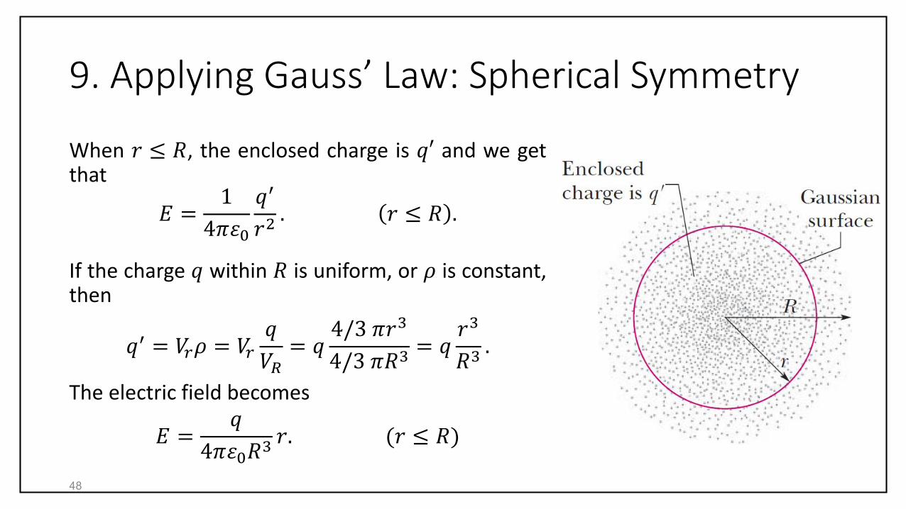
9. Applying Gauss’ Law: Spherical Symmetry
When 𝑟 ≤ 𝑅, the enclosed charge is 𝑞′ and we getthat
𝐸 =1
4𝜋𝜀0
𝑞′
𝑟2. 𝑟 ≤ 𝑅 .
If the charge 𝑞 within 𝑅 is uniform, or 𝜌 is constant,then
𝑞′ = 𝑉𝑟𝜌 = 𝑉𝑟
𝑞
𝑉𝑅= 𝑞
4/3 𝜋𝑟3
4/3 𝜋𝑅3= 𝑞
𝑟3
𝑅3.
The electric field becomes
𝐸 =𝑞
4𝜋𝜀0𝑅3𝑟. (𝑟 ≤ 𝑅)
48

9. Applying Gauss’ Law: Spherical Symmetry
3 & 4, 2 then 1.
49