Chapter 3staff.cs.psu.ac.th/sathit/ComOr/Ch03-1.pdf · · 2017-09-253.2.5 Representing Boolean...
75
Chapter 3 Boolean Algebra and Digital Logic
Transcript of Chapter 3staff.cs.psu.ac.th/sathit/ComOr/Ch03-1.pdf · · 2017-09-253.2.5 Representing Boolean...

Chapter 3 Boolean Algebra and
Digital Logic

2
Chapter 3 Objectives
• Understand the relationship between Boolean logic
and digital computer circuits.
• Learn how to design simple logic circuits.
• Understand how digital circuits work together to
form complex computer systems.

3
3.1 Introduction
• In the latter part of the nineteenth century, George
Boole incensed philosophers and mathematicians
alike when he suggested that logical thought could
be represented through mathematical equations.
• Computers, as we know them today, are
implementations of Boole’s Laws of Thought.

4
3.1 Introduction
• In the middle of the twentieth century, computers
were commonly known as “thinking machines” and
“electronic brains.”
– Many people were fearful of them.
• Nowadays, we rarely ponder the relationship
between electronic digital computers and human
logic. Computers are accepted as part of our lives.
5
3.2 Boolean Algebra
• Boolean algebra is a mathematical system for
the manipulation of variables that can have one
of two values.
– In formal logic, these values are “true” and “false.”
– In digital systems, these values are “on” and “off” 1
and 0, or “high” and “low.”
• Boolean expressions are created by performing
operations on Boolean variables.
– Common Boolean operators include AND, OR, and
NOT.
6
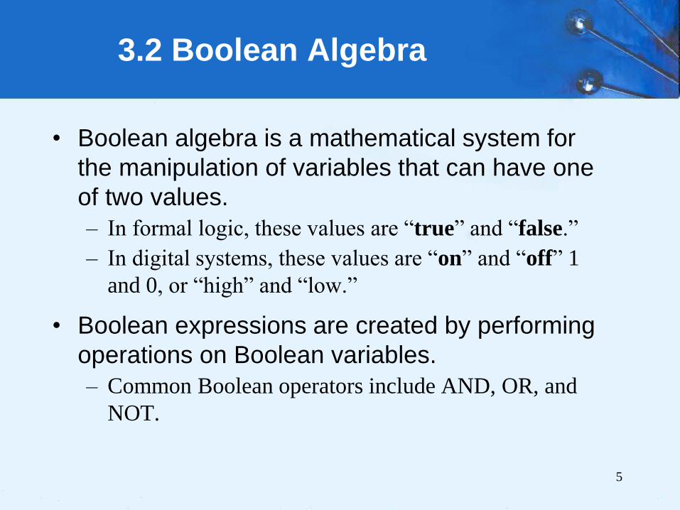
3.2 Boolean Algebra
• A Boolean operator can be
completely described using a
truth table.
• The truth table for the Boolean
operators AND and OR are
shown at the right.
• The AND operator is also known
as a Boolean product. The OR
operator is the Boolean sum.

7
3.2 Boolean Algebra
• The truth table for the
Boolean NOT operator is
shown at the right.
• The NOT operation is
most often designated
by an overbar. It is
sometimes indicated by
a prime mark ( ‘ ) or an
“elbow” ().
8
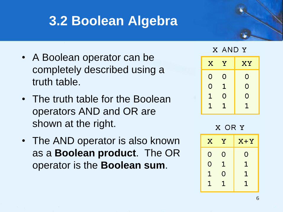
3.2 Boolean Algebra
• A Boolean function has:
• At least one Boolean variable,
• At least one Boolean operator, and
• At least one input from the set {0,1}.
• It produces an output that is also a member of
the set {0,1}.
x y
9
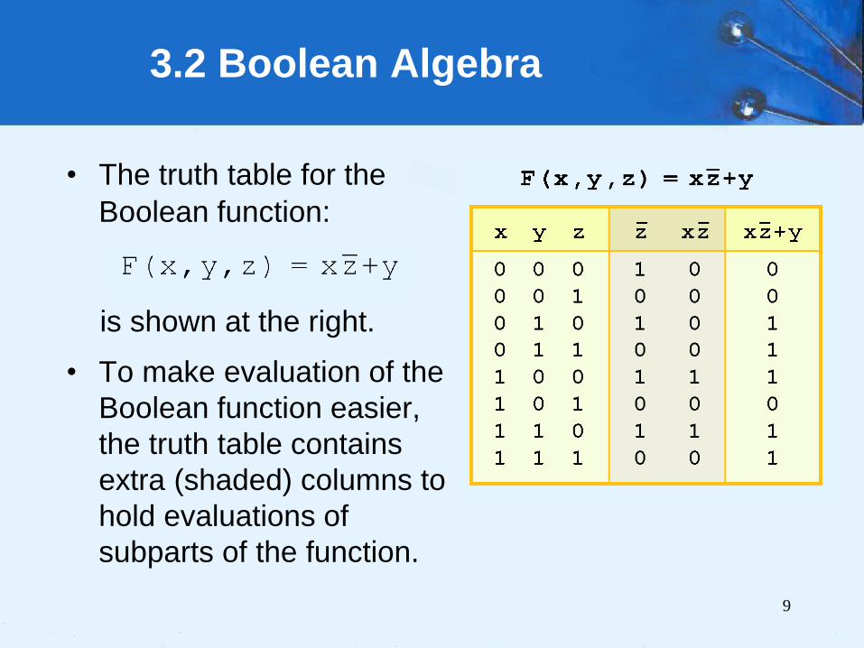
3.2 Boolean Algebra
• The truth table for the
Boolean function:
is shown at the right.
• To make evaluation of the
Boolean function easier,
the truth table contains
extra (shaded) columns to
hold evaluations of
subparts of the function.

10
3.2 Boolean Algebra
• As with common
arithmetic, Boolean
operations have rules of
precedence.
• The NOT operator has
highest priority, followed
by AND and then OR.
• This is how we chose the
(shaded) function
subparts in our table.
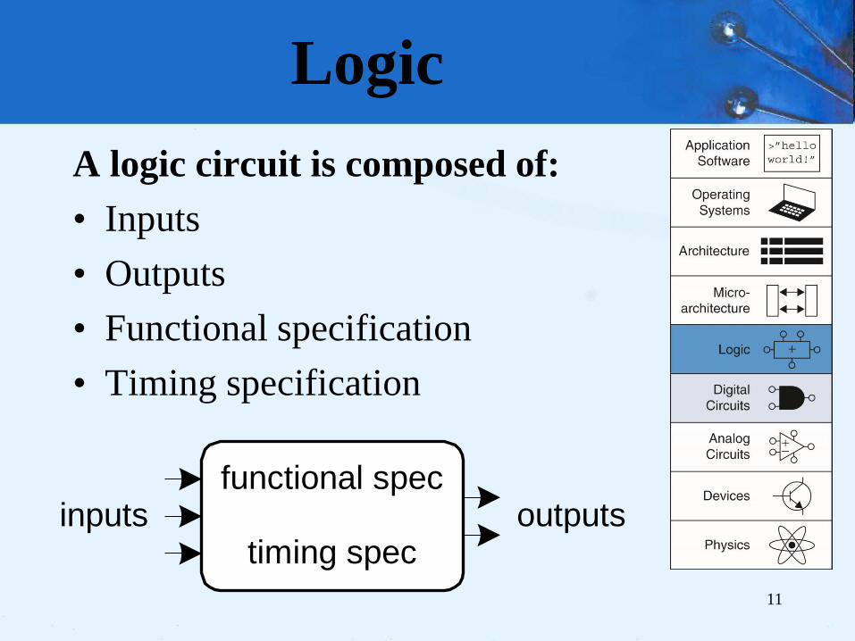
Logic
A logic circuit is composed of:
• Inputs
• Outputs
• Functional specification
• Timing specification
11
inputs outputsfunctional spec
timing spec

Circuits
• Nodes – Inputs: A, B, C
– Outputs: Y, Z
– Internal: n1
• Circuit elements – E1, E2, E3
– Each a circuit
12
A E1
E2
E3B
C
n1
Y
Z

Types of Logic Circuits
• Combinational Logic
– Memoryless
– Outputs determined by current values of inputs
• Sequential Logic
– Has memory
– Outputs determined by previous and current values of
inputs
13
inputs outputsfunctional spec
timing spec

Combinational Logic
14
ZX
ZX Y
Functional specification expresses as a truth table or a
Boolean equation:

3.2.2 Boolean Identities
• Axioms and theorems of Boolean algebra obey the
principle of duality.
• If the symbols 0 and 1 and the operators • (AND)
and + (OR) are interchanged, the statement will
still be correct.
• Symbol (′) denote the dual of a statement.
15
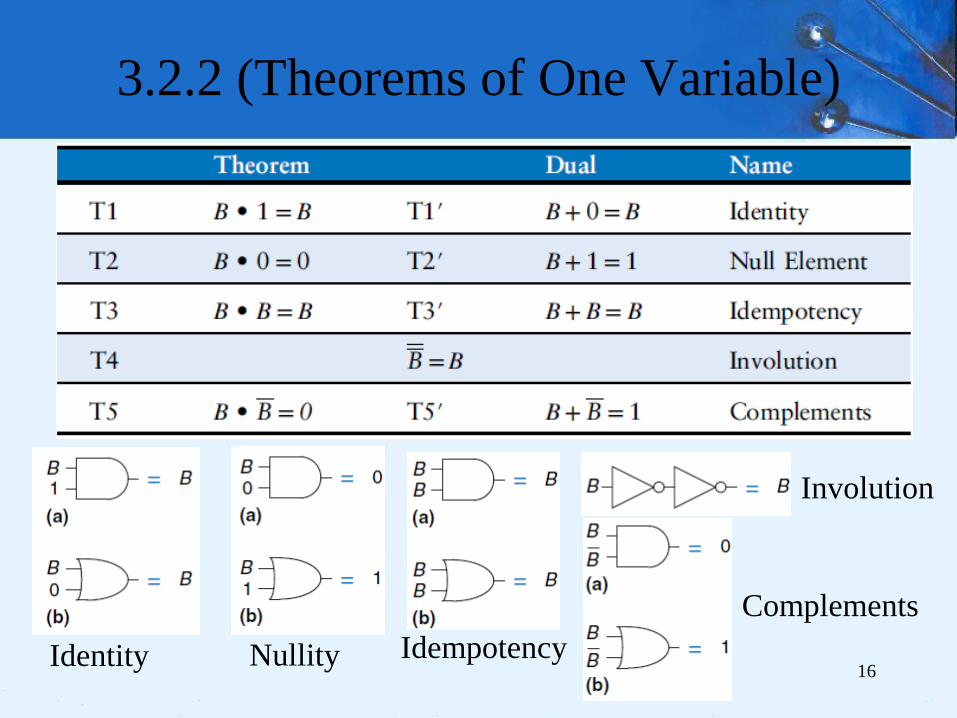
3.2.2 (Theorems of One Variable)
16 Identity Nullity Idempotency
Involution
Complements

3.2.2 (Theorems of Several Variables)
17
B C B+C B(B+C)=B
0
0
1
1
0
1
0
1
0
1
1
1
0
0
1
1
B C C’ B+C B+C’ (B+C)(B+C’)=B
0
0
1
1
0 1
1 0
0 1
1 0
0
1
1
1
1
0
1
1
0
0
1
1

3.2.2 Boolean Identities
18

3.2.3 Simplification of Boolean Expressions
• Ex: Given the function F(x,y,z) = x′yz +
x′yz′ + xz, we simplify as follows
19
• Ex: Given the function F(x,y) = y + (xy)′,
we simplify as follows:

3.2.3 Simplification of Boolean Expressions
• Ex: Given the function F(x,y) = x′(x + y) +
(y + x)(x + y′), we simplify as follows:
20

3.2.4 Complements
• The most common Boolean operator
applied to more complex Boolean
expressions is the NOT operator, resulting
in the complement of the expression.
• To find the complement of a Boolean
function, we use DeMorgan’s theorem T12.
• The OR form of this law states that (x + y)′
= x′y′.
21

3.2.4 Complements
• We can easily extend DeMorgan’s Law to three
or more variables as follows:
• Given the function: F(x,y,z) = (x+y+z).
• Then F′(x,y,z) = (x + y + z)′.
• Let w = (x + y). Then F′(x,y,z) = (w + z)′ = w′z′.
• Now, applying DeMorgan’s Law again, we get:
w′z′ = (x + y)′z′ = x′y′z′ = F′(x,y,z)
• If F(x,y,z) = (x + y + z), then F′(x,y,z) = x′y′z′.
so that, (xyz)′ = x′ + y′ + z′. 22

3.2.4 Complements
23
Table depicts the truth tables for F(x,y,z) = x′ +
yz′ and its complement, F′(x,y,z) = x(y′ + z).

3.2.4 Complements
24
• DeMorgan’s law can be extended to any number of
variables.
• Replace each variable by its complement and
change all ANDs to ORs and all ORs to ANDs.
• Thus, we find the the complement of:
3.2.5 Representing Boolean Functions
• There are an infinite number of Boolean
expressions that are logically equivalent to
one another, as seen in Ex.
• Ex: Suppose F(x,y,z) = x + xy′. We can also
express F as F(x,y,z) = x + x + xy′
• From idempotent Law, these two expressions
are the same.
25

SOP/POS
• Simplify Boolean function to the form
canonical, or standardized.
• For any given Boolean function, there exists
a unique standardized form. But, there are
different “standards” that designers use.
• The two most common are:
– the sum-of-products (SOP) form and
– the product-of-sums (POS) form.
26

27

28

Sum-Of-Products form
• SOP collects of ANDed variables.
• F1(x,y,z) = xy + yz′ + xyz is in SOP form.
• F2(x,y,z) = xy′ + x (y + z′) is not in SOP
form.
• Apply the Distributive Law to distribute
the x variable in F2, now F2(x,y,z) = xy′+
xy + xz′, which is in SOP form.
29

SUM-OF-PRODUCTS FORM
• Ben Bitdiddle is
having a picnic.
He won’t enjoy
it if it rains or if
there are ants.
• Design a circuit
that will output
TRUE only if
Ben enjoys the
picnic. 30

SUM-OF-PRODUCTS FORM
Ants Rain Enjoy
0 0 1
0 1 0
1 0 0
1 1 0
31
𝐸 = 𝐴 𝐵
32

33

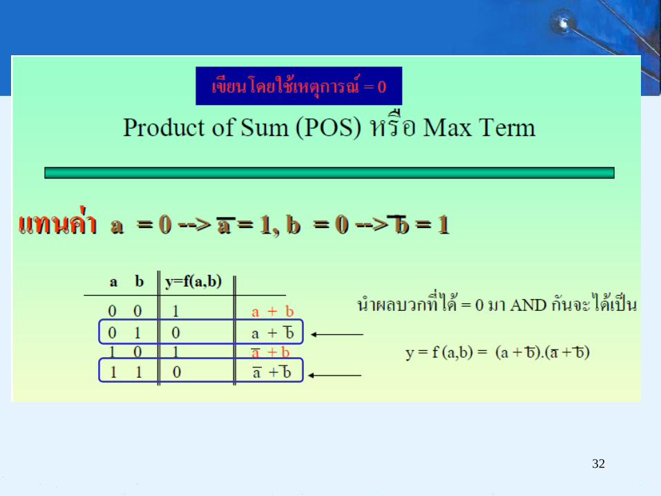
Product-Of-Sums form
• POS consists of ORed variables (sum
terms) that are ANDed together.
• F1(x,y,z) = (x + y) (x + z′)(y + z′)(y + z) is in
POS form.
• Ex: from Ben’s picnic
POS:
𝐸 = 𝐴 + 𝑅 𝐴 + 𝑅 𝐴 + 𝑅
34
Ants Rain Enjoy
0 0 1
0 1 0
1 0 0
1 1 0

Simplifying Equations
• Consider the sum-of-products expression
𝑌 = 𝐴 𝐵 + 𝐴𝐵 : By Theorem T10, the
equation simplifies to 𝑌 = 𝐵 .
𝑌 = 𝐴 𝐵 + 𝐴𝐵
𝑌 = 𝐴 + 𝐴 𝐵
𝑌 = 1𝐵
35

Simplifying Equations
• Consider the sum-of-products expression
𝑌 = 𝐴 𝐵 + 𝐴𝐵 : By Theorem T10, the
equation simplifies to 𝑌 = 𝐵 .
• Ex: Minimize Equation 𝐴′𝐵′𝐶′ + 𝐴𝐵′𝐶′ +𝐴𝐵′𝐶
36

Improved equation minimization
𝐴′𝐵′𝐶′ + 𝐴𝐵′𝐶′ + 𝐴𝐵′𝐶
37

K-maps
• Karnaugh maps (K-maps)
are a graphical method for
simplifying Boolean
equations.
• They were invented in 1953
by Maurice Karnaugh. K-
maps work well for problems
with up to four variables.
41
Maurice Karnaugh, 1924–.
Graduated with a bachelor’s
degree in physics from the
City College of New York in
1948 and earned a Ph.D. in
physics from Yale in 1952.
Worked at Bell Labs and
IBM from 1952 to 1993 and
as a computer science
professor at the Polytechnic
University of New York from
1980 to 1999.
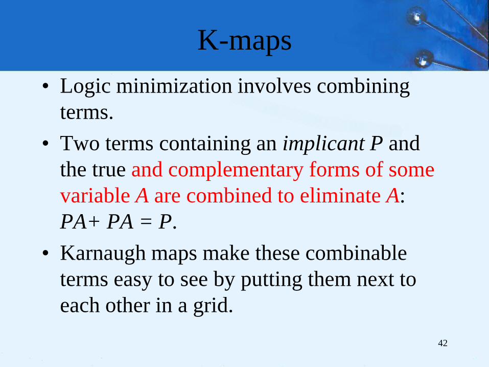
K-maps
• Logic minimization involves combining
terms.
• Two terms containing an implicant P and
the true and complementary forms of some
variable A are combined to eliminate A:
PA+ PA = P.
• Karnaugh maps make these combinable
terms easy to see by putting them next to
each other in a grid.
42

Karnaugh Maps to Represent
Boolean Functions
43

44
K-map of 3 variables

Logic Minimization with
K-Maps
• K-maps help us do this simplification
graphically by circling 1’s in adjacent
squares, as shown in the map.
• As before, we can use Boolean algebra to
minimize equations in SOP form.
45
𝑌 = 𝐴 𝐵

Logic Minimization with
K-Maps Rules for finding a minimized equation from a K-
map are as follows:
• Use the fewest circles necessary to cover all the 1’s.
• All the squares in each circle must contain 1’s.
• Each circle must span a rectangular block that is a
power of 2 (i.e.,1, 2, or 4) squares in each direction.
• Each circle should be as large as possible.
• A circle may wrap around the edges of the K-map.
• A 1 in a K-map may be circled multiple times if
doing so allows fewer circles to be used. 46

MINIMIZATION OF A THREE-VARIABLE
FUNCTION USING A K-MAP
• Each circle in the K-map represents
a prime implicant, and the
dimension of each circle is a power
of two (2 × 1 and 2 × 2).
47

51

53
A B C D Y
0
0
0
0
0
0
0
0
0
0
0
0
1
1
1
1
0
0
1
1
0
0
1
1
0
1
0
1
0
1
0
1
0
0
0
0
0
1
0
0
1
1
1
1
1
1
1
1
0
0
0
0
1
1
1
1
0
0
1
1
0
0
1
1
0
1
0
1
0
1
0
1
0
0
0
1
0
1
0
1

55
• We have looked at Boolean functions in abstract
terms.
• In this section, we see that Boolean functions are
implemented in digital computer circuits called
gates.
• A gate is an electronic device that produces a result
based on two or more input values.
– In reality, gates consist of one to six transistors, but digital
designers think of them as a single unit.
– Integrated circuits contain collections of gates suited to a
particular purpose.
3.3 Logic Gates

56
• The three simplest gates are the AND, OR, and NOT
gates.
• They correspond directly to their respective Boolean
operations, as you can see by their truth tables.
3.3 Logic Gates
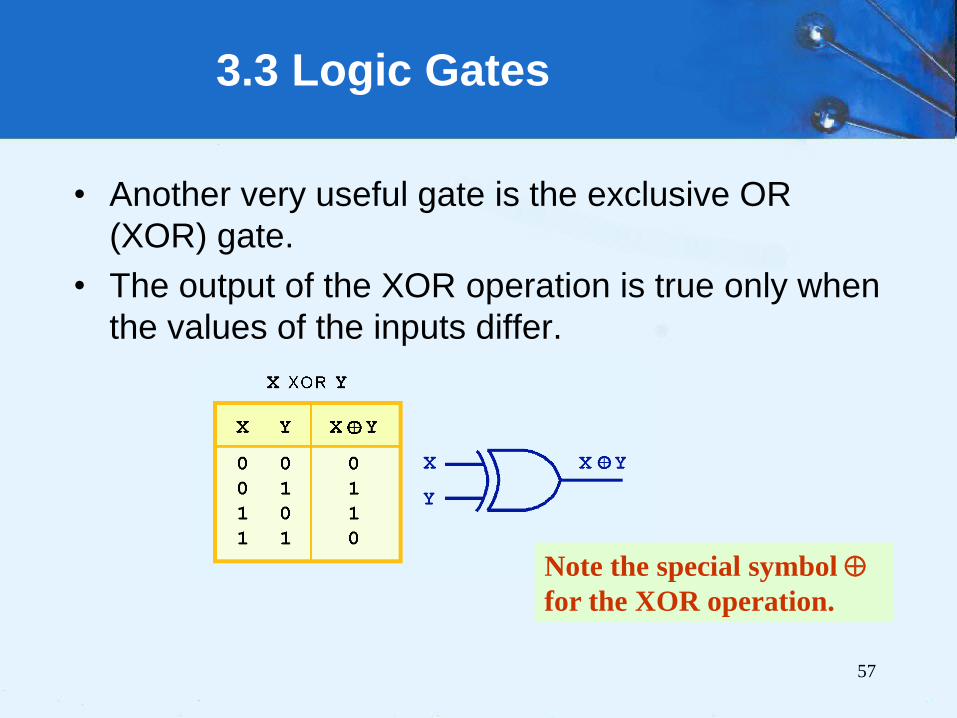
57
• Another very useful gate is the exclusive OR
(XOR) gate.
• The output of the XOR operation is true only when
the values of the inputs differ.
3.3 Logic Gates
Note the special symbol
for the XOR operation.

58
• NAND and NOR
are two very
important gates.
Their symbols and
truth tables are
shown at the right.
3.3 Logic Gates

59
3.3 Logic Gates
• NAND and NOR
are known as
universal gates
because they are
inexpensive to
manufacture and
any Boolean
function can be
constructed using
only NAND or only
NOR gates.

60
3.3 Logic Gates
• Gates can have multiple inputs and more than
one output.
– A second output can be provided for the complement
of the operation.
– We’ll see more of this later.
AND Gate with Two
Inputs and Two Outputs Three-Input AND
Gate Representing
x y′z
A Three-Input OR
Gate Representing
x + y + z

3.3 Logic Gates
Drawing schematics, we make them easier to read
and debug, generally use the following guidelines:
• Inputs are on the left side.
• Outputs are on the right side.
• Gates should flow from left to right.
• Drawing with straight wires.
• Wires always connect at a T junction.
• A dot where wires cross indicates a connection
between the wires.
• Wires crossing without a dot make no connection. 61

63
3.5 Combinational Circuits
• We have designed a circuit that implements the
Boolean function:
• This circuit is an example of a combinational logic
circuit.
• Combinational logic circuits produce a specified
output (almost) at the instant when input values
are applied.
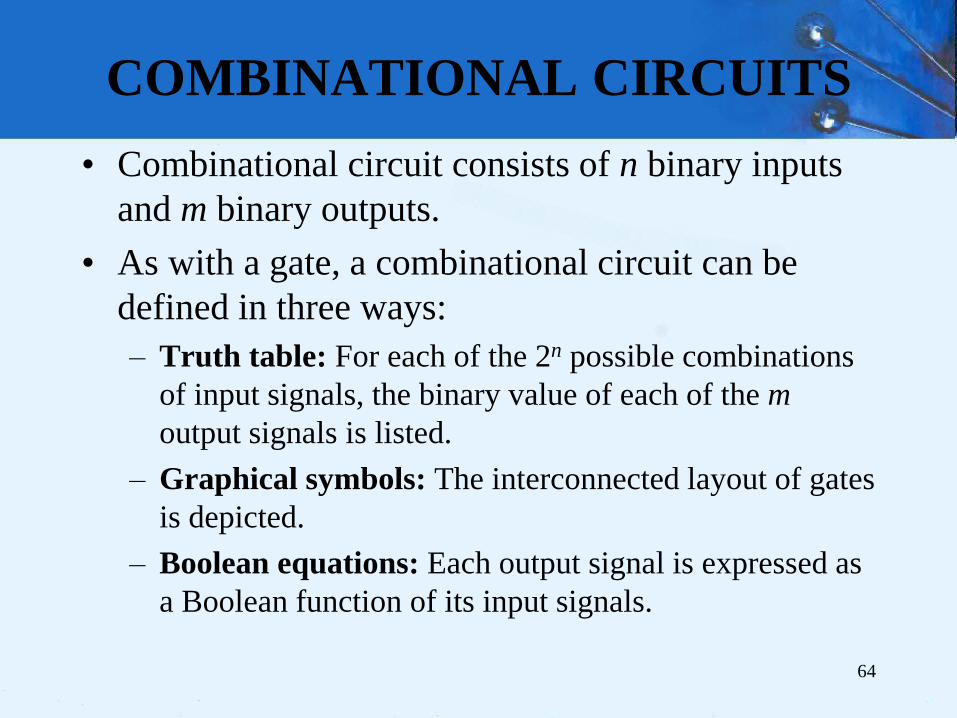
COMBINATIONAL CIRCUITS
• Combinational circuit consists of n binary inputs
and m binary outputs.
• As with a gate, a combinational circuit can be
defined in three ways:
– Truth table: For each of the 2n possible combinations
of input signals, the binary value of each of the m
output signals is listed.
– Graphical symbols: The interconnected layout of gates
is depicted.
– Boolean equations: Each output signal is expressed as
a Boolean function of its input signals.
64

65
3.5 Combinational Circuits
• One of the simplest
is the half adder to
find the sum of two
bits.
• Construction of a
half adder by
looking at its truth
table.
𝑓 𝑥, 𝑦 = 𝑥⨁𝑦
𝑓 𝑥, 𝑦 = 𝑥𝑦

69
3.5 Combinational Circuits

70
3.5 Combinational Circuits

71
3.5 Combinational Circuits

73
3.5 Combinational Circuits
• How can we change the
half adder shown below
to make it a full adder?
74
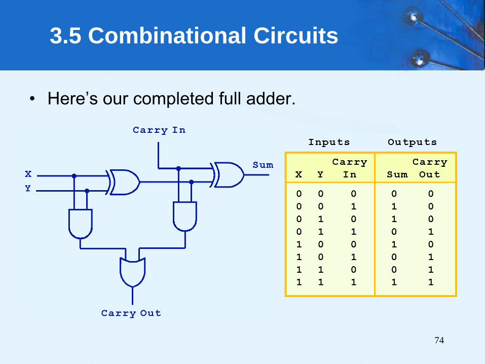
3.5 Combinational Circuits
• Here’s our completed full adder.

75
3.5 Combinational Circuits

76
3.5 Combinational Circuits

77
3.5 Combinational Circuits

78
3.5 Combinational Circuits

79
3.5 Combinational Circuits

80
3.5 Combinational Circuits
• Just as we combined half adders to make a full
adder,
• Full adders can connected in series, 8 or 16 bits.
• By replicating the above circuit 16 times,
• feeding the Carry Out of one circuit into the Carry
In of the circuit immediately to its left.
• This configuration is called a ripple-carry adder.

82
3.5 Combinational Circuits
• Decoders are another important type of
combinational circuit.
• Among other things, they are useful in selecting a
memory location according a binary value placed
on the address lines of a memory bus.
• Address decoders with n inputs can select any of 2n
locations.
This is a block
diagram for a
decoder.

83
3.5 Combinational Circuits
• This is what a 2-to-4 decoder looks like on the
inside.
If x = 0 and y = 1,
which output line
is enabled?

84
3.5 Combinational Circuits
• A multiplexer does just the
opposite of a decoder.
• It selects a single output
from several inputs.
• The particular input chosen
for output is determined by
the value of the multiplexer’s
control lines. This is a block
diagram for a
multiplexer.

85
3.5 Combinational Circuits
• This is what a 4-to-1 multiplexer looks like on the
inside.
If S0 = 1 and S1 = 0,
which input is
transferred to the
output?

A Simple Two-Bit ALU
87

A Simple Two-Bit ALU
88
0
0

A Simple Two-Bit ALU
89
0
1

90
End of Chapter 3