Chapter 4widodo.com/interfacing/serialcomm.pdf · 2016-05-09 · languages such as Visual Basic,...
14
Chapter 4 Serial Communication with Robot
Transcript of Chapter 4widodo.com/interfacing/serialcomm.pdf · 2016-05-09 · languages such as Visual Basic,...

Chapter 4
Serial Communication with Robot

http://www.sciencepublishinggroup.com 65
On successful completion of this course, students will be able to:
Explain principle of serial communication for robotics.
Program the mobile robot using serial and wireless
communication.
Develop an interface program using Visual Basic/C# .Net.
Introduction
We need data communication to sending and receiving serial data using RS-
232 Communication or wirelessly between microcontrollers or to a PC. 433
MHz RF Transceiver with Low power consumption makes it ideal for use in
battery-powered applications. Data is sent and received by AM or CPCA
modulation, thus offering a higher average output power which extends the
range. Digi XBee 802.15.4 modules are the easiest-to-use, most reliable and
cost-effective RF devices we’ve experienced. The 802.15.4 XBee modules
provide two friendly modes of communication – a simple serial method of
transmit/receive or a framed mode providing advanced features. XBee are ready
to use out of the package, or they can be configured through the X-CTU utility
or from your microcontroller.
Serial Interface Using Microsoft Visual Basic/C# .Net
RS-232 stands for Recommend Standard number 232 and C is the latest
revision of the standard. The serial ports on most computers use a subset of the
RS-232C standard. The full RS-232C standard specifies a 25-pin "D" connector
of which 22 pins are used. Most of these pins are not needed for normal PC
communications, and indeed, most new PCs are equipped with male D type
connectors having only 9 pins. The baud unit is named after Jean Maurice Emile
Baudot, who was an officer in the French Telegraph Service. He is credited with
devising the first uniform-length 5-bit code for characters of the alphabet in the
late 19th century. What baud really refers to is modulation rate or the number of
times per second that a line changes state. This is not always the same as bits
per second (BPS). If you connect two serial devices together using direct cables
then baud and BPS are in fact the same. Thus, if you are running at 19200 BPS,
then the line is also changing states 19200 times per second.

Modern Robotics with OpenCV
66 http://www.sciencepublishinggroup.com
There are two basic types of serial communications, synchronous and
asynchronous. With Synchronous communications, the two devices initially
synchronize themselves to each other, and then continually send characters to
stay in sync. Even when data is not really being sent, a constant flow of bits
allows each device to know where the other is at any given time. That is, each
character that is sent is either actual data or an idle character. Synchronous
communications allows faster data transfer rates than asynchronous methods,
because additional bits to mark the beginning and end of each data byte are not
required. The serial ports on IBM-style PCs are asynchronous devices and
therefore only support asynchronous serial communications.
Asynchronous means "no synchronization", and thus does not require sending
and receiving idle characters. However, the beginning and end of each byte of
data must be identified by start and stop bits. The start bit indicate when the
data byte is about to begin and the stop bit signals when it ends. The
requirement to send these additional two bits causes asynchronous
communications to be slightly slower than synchronous. When transmitting a
byte, the UART (serial port) first sends a START BIT which is a positive
voltage (0), followed by the data (general 8 bits, but could be 5, 6, 7, or 8 bits)
followed by one or two STOP BITs which is a negative(1) voltage. The
sequence is repeated for each byte sent. Figure 4.1 shows a diagram of a byte
transmission would look like.
Figure 4.1 Serial communication format[1].
To create a serial interface program for PC, we can use many programming
languages such as Visual Basic, Visual C # or Borland Delphi. Ms. Visual C #.
Net 2010/2013 is one of the programming languages that allow us to create GUI
applications for communication with the robot. There SerialPort class can be
used to access serial port. Program for serial communication on propeller is
quite easy because it uses objects, such as Parallax Serial Terminal, for example:

Chapter 4 Serial Communication with Robot
http://www.sciencepublishinggroup.com 67
Figure 4.2 Serial communication between PC and the Propeller Microcontroller.
You can download Ms. Visual Studio 2013 Express edition to use this
program. Once installed, create a form like the following by putting 2 button,
Modern Robotics with OpenCV
68 http://www.sciencepublishinggroup.com
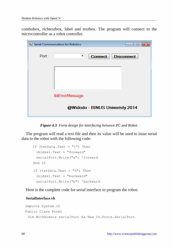
combobox, richtextbox, label and textbox. The program will connect to the
microcontroller as a robot controller.
Figure 4.3 Form design for interfacing between PC and Robot.
The program will read a text file and then its value will be used to issue serial
data to the robot with the following code:
If (txtData.Text = "1") Then
lblAksi.Text = "forward"
serialPort.Write("a") 'forward
End If
If (txtData.Text = "0") Then
lblAksi.Text = "backward"
serialPort.Write("b") 'backward
Here is the complete code for serial interface to program the robot:
SerialInterface.vb
imports System.IO
Public Class Form1
Dim WithEvents serialPort As New IO.Ports.SerialPort

Chapter 4 Serial Communication with Robot
http://www.sciencepublishinggroup.com 69
Private Sub Form1_Load(ByVal sender As System.Object, ByVal e
As System.EventArgs) Handles MyBase.Load
displayPort()
cbComPorts.SelectedIndex = 1
End Sub
Private Sub btnConnect_Click(ByVal sender As System.Object,
ByVal e As System.EventArgs) Handles btnConnect.Click
If serialPort.IsOpen Then
serialPort.Close()
End If
Try
With serialPort ‘configuring port
.PortName = cbComPorts.Text
.BaudRate = 9600
.Parity = IO.Ports.Parity.None
.DataBits = 8
.StopBits = IO.Ports.StopBits.One
End With
serialPort.Open()
lblMessage.Text = cbComPorts.Text & " Connected"
btnConnect.Enabled = False
btnDisconnect.Enabled = True
Catch ex As Exception
MsgBox(ex.ToString)
End Try
Timer1.Enabled = True
Timer1.Interval = 100
End Sub
Private Sub datareceived(ByVal sender As Object, ByVal e As
System.IO.Ports.SerialDataReceivedEventArgs) Handles
serialPort.DataReceived
'RichTextBox1.Invoke(New myDelegate(AddressOf updateTextBox),
New Object() {})
End Sub
Public Sub updatetextbox()
RichTextBox1.Text = ""

Modern Robotics with OpenCV
70 http://www.sciencepublishinggroup.com
With RichTextBox1
.AppendText(serialPort.ReadExisting)
End With
End Sub
Private Sub btnDisconnect_Click(ByVal sender As System.Object,
ByVal e As System.EventArgs) Handles btnDisconnect.Click
Try
serialPort.Close()
lblMessage.Text = serialPort.PortName & " Disconnected ."
btnConnect.Enabled = True
btnDisconnect.Enabled = False
Catch ex As Exception
MsgBox(ex.ToString)
End Try
End Sub
Private Sub Timer1_Tick(ByVal sender As System.Object, ByVal e
As System.EventArgs) Handles Timer1.Tick
Try
Dim fs As New FileStream("c:/position.txt", FileMode.Open,
FileAccess.Read)
txtData.Text = ""
Dim d As New StreamReader(fs)
d.BaseStream.Seek(0, SeekOrigin.Begin)
While d.Peek() > -1
txtData.Text &= d.ReadLine()
End While
d.Close()
If (txtData.Text = "1") Then
lblAksi.Text = "forward"
serialPort.Write("a") 'forward
End If
If (txtData.Text = "0") Then
lblAksi.Text = "backward"
serialPort.Write("b") 'backward
End If
Chapter 4 Serial Communication with Robot
http://www.sciencepublishinggroup.com 71
Catch ea As Exception
'MessageBox.Show(ea.Message)
End Try
End Sub
End Class
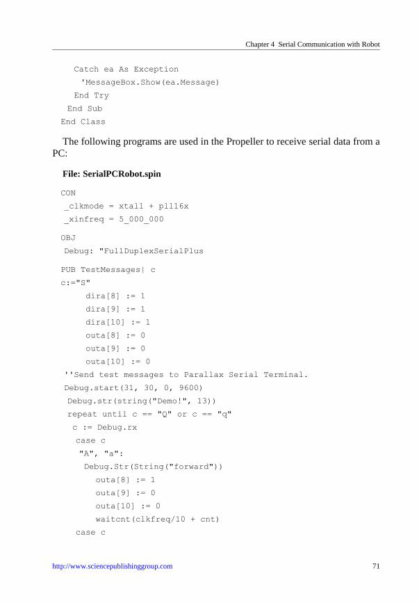
The following programs are used in the Propeller to receive serial data from a
PC:
File: SerialPCRobot.spin
CON
_clkmode = xtal1 + pll16x
_xinfreq = 5_000_000
OBJ
Debug: "FullDuplexSerialPlus
PUB TestMessages| c
c:="S"
dira[8] := 1
dira[9] := 1
dira[10] := 1
outa[8] := 0
outa[9] := 0
outa[10] := 0
''Send test messages to Parallax Serial Terminal.
Debug.start(31, 30, 0, 9600)
Debug.str(string("Demo!", 13))
repeat until c == "Q" or c == "q"
c := Debug.rx
case c
"A", "a":
Debug.Str(String("forward"))
outa[8] := 1
outa[9] := 0
outa[10] := 0
waitcnt(clkfreq/10 + cnt)
case c

Modern Robotics with OpenCV
72 http://www.sciencepublishinggroup.com
"B", "b":
Debug.Str(String("backward"))
outa[8] := 0
outa[9] := 1
outa[10] := 0
waitcnt(clkfreq/10 + cnt)
"C", "c":
Debug.Str(String("turn left"))
outa[8] := 0
outa[9] := 0
outa[10] := 1
waitcnt(clkfreq/10 + cnt)
"Q", "q": quit
Wireless Communication for Robot
433 MHz Transceiver
433 MHz Transceiver is an easy-to-use module is capable of sending and
receiving serial data wirelessly between microcontrollers or to a PC. Low power
consumption makes it ideal for use in battery-powered applications. Data is sent
and received by AM or CPCA modulation, thus offering a higher average
output power which extends the range. This module is equipped with an RSSI
feature that can be utilized to improve power efficiency by waking up circuitry
only when an external signal is detected.

Chapter 4 Serial Communication with Robot
http://www.sciencepublishinggroup.com 73
Figure 4.4 Wireless communication using 433 MHz Transeiver.
XBee Transceiver
XBee 1 mW Wire Antenna 802.15.4 modules are the easiest-to-use, most
reliable and cost-effective RF devices we’ve experienced. The 802.15.4 XBee
modules provide two friendly modes of communication – a simple serial
method of transmit/receive or a framed mode providing advanced features.
XBees are ready to use out of the package, or they can be configured through
the X-CTU utility or from your microcontroller. These modules can
communicate point to point, from one point to a PC, or in a mesh network.
You only need to choose an antenna style (PCB or wire) and power level (1
mW for up to 300 ft and 60 mW for up to 1 mile). The PCB antenna version
provides a lower profile footprint for applications with limited space while the

Modern Robotics with OpenCV
74 http://www.sciencepublishinggroup.com
wire antenna version allows for more flexibility in adjusting for optimal range at
the same output power. XBee 802.15.4 modules are cross-compatible with other
802.15.4 XBee modules, regardless of antenna type or power rating.
Key Features:
Outdoor range up to 300 feet (90 m) line of sight.
Indoor range up to 100 feet (30 m).
Data rate up to 250 Kbps.
2.4 GHz frequency band (accepted world-wide).
Figure 4.5 Wireless ommunication using XBee.
XBee Transceiver AT-API Object is an object for communicating with Digi's
XBee (designed/tested with Series 1 - 802.15.4) transceivers in both transparent
(AT) and API mode. API mode involves framed data with information such as
sender's address and RSSI levels. RN-42 Bluetooth Module
The RN-42 Bluetooth Module provides a reliable method for creating a
wireless serial communication interface between two devices such as a
microcontroller, PC, cell phone, or another module for robotics application.
This module can pair up with devices supporting Bluetooth SPP (Serial Port
Profile) to establish a serial interface. The RN-42 Bluetooth Module is
breadboard-friendly and is compatible with all 5 V and 3.3 V microcontroller
platforms.

Chapter 4 Serial Communication with Robot
http://www.sciencepublishinggroup.com 75
Key Features:
Fully qualified Bluetooth 2.1/2.0/1.2/1.1 module provides compatibility
with many devices.
Low power consumption for long-lasting battery-powered projects.
Auto-connect/discovery/pairing modes make connecting to other modules
easy.
LED indicators provide visual status of connection/mode.
Voltage jumper selects for use with 5 V and 3.3 V microcontrollers.
When pairing the RN-42 with another device such as a laptop or cell phone
the default passkey is “1234”. The device is discovered as RN42-xxxx (where
xxxx is the last 4 digits of the device MAC address). On a PC with Bluetooth
the device will have a COM port assigned to it. When this COM port is opened
the PC should reconnect to the module (the Blue LED should light up). At this
point you can send/receive serial data.
Exercises
1) Write an interface using C# to control robot using PC.
2) Write wireless program to control robot using PC.
References
[1] Stallings W., Data and Computer Communications, Prentice Hall Publisher, 2011.
[2] www.parallax.com.