Chapter 2 Steel Fiber Reinforced Concrete
25
Steel Fiber Reinforced Concrete GroWld Slabs Chapter 2 Steel Fiber Reinforced Concrete 2.1 Synopsis Different types of steel fibers can be used to reinforce concrete. Steel fibers are generally classified depending on their manufacturing method. stainless steel has proven to give the best performance. The addition of steel fibers to concrete necessitate an alteration to the mix design to compensate for the loss of workability due to the extra paste required for coating the surface of the added steel fibers. While many technical and economical advantages are benefited from using SFRC, drawbacks can also be found. They are however not likely to cause major problems. It was thought that steel fibers will have negative implications in concrete practice (i.e. transporting, surfacing, finishing etc), but experience has shown that the influence of steel fibers on these practical aspects is negligible. Dispersion of steel fibers in concrete alter its engineering characteristics. The mechanism associated with the SFRC positively influences its mechanical and physical properties. The improvement differs depending upon the dosage and the steel fiber parameters considering the other strength-determining factors to be constant. 2.2 Steel Fibers There are a number of different types of steel fibers with different commercial names. Basically, steel fibers can be categorized into four groups depending on the manufacturing process viz: cut wire (cold drawn), slit sheet, melt extract and mill cut. It can also be classified according to its shape and/or section. Various notations were previously used to nominate the specific type of the steel fibers but in this dissertation the following notations are used: • (h x w x 1) to nominate the straight rectangular section steel fibers. The letters h, w and 1 stand for section depth, width and the fiber length respectively. • (d x 1) was used to name circular or semi-circular section straight or deformed steel fibers, d and I stand for diameter and length respectively. • Hook-ended steel fiber (Le. 80/60 H means aspect ratiolLength of steel fiber). 2-1
Transcript of Chapter 2 Steel Fiber Reinforced Concrete

Steel Fiber Reinforced Concrete GroWld Slabs
Chapter 2
Steel Fiber Reinforced Concrete
2.1 Synopsis
Different types of steel fibers can be used to reinforce concrete. Steel fibers are
generally classified depending on their manufacturing method. Hooked~end stainless
steel has proven to give the best performance. The addition ofsteel fibers to concrete
necessitate an alteration to the mix design to compensate for the loss of workability
due to the extra paste required for coating the surface of the added steel fibers. While
many technical and economical advantages are benefited from using SFRC,
drawbacks can also be found. They are however not likely to cause major problems.
It was thought that steel fibers will have negative implications in concrete practice
(i.e. transporting, surfacing, finishing etc), but experience has shown that the
influence of steel fibers on these practical aspects is negligible.
Dispersion of steel fibers in concrete alter its engineering characteristics. The
after~crack mechanism associated with the SFRC positively influences its mechanical
and physical properties. The improvement differs depending upon the dosage and the
steel fiber parameters considering the other strength-determining factors to be
constant.
2.2 Steel Fibers
There are a number of different types of steel fibers with different commercial
names. Basically, steel fibers can be categorized into four groups depending on the
manufacturing process viz: cut wire (cold drawn), slit sheet, melt extract and mill
cut. It can also be classified according to its shape and/or section. Various notations
were previously used to nominate the specific type of the steel fibers but in this
dissertation the following notations are used:
• (h x w x 1) to nominate the straight rectangular section steel fibers. The
letters h, w and 1 stand for section depth, width and the fiber length
respectively.
• (d x 1) was used to name circular or semi-circular section straight or
deformed steel fibers, d and I stand for diameter and length respectively.
• Hook-ended steel fiber (Le. 80/60 H means aspect ratiolLength of steel
fiber).
2-1

Steel Fiber Reinforced
Concrete Ground Slabs The popular shapes, sections used and the recent standard notations are compiled in
figure 2-1.
Straight slit Machined Deformed slit sheet or wire sheet or wire chips
[] or 0 o or,=,D o
Melt extract Hooked-end wire (Crimped) Enlarged-end
Steel Fiber Manufacturers Notations
CHD NB
R c
JIrilrmaI Dnl!hl l.uw s.e,,1
Camoo
B N Low
Carbon
Figure 2-1: Types and Notations a/Steel Fibers
2-2

Steel Fiber Reinforced Concrete Ground Slabs
Major efforts have been made in recent years to optimize the shape and size of the
steel fibers to achieve improved fiber-matrix bond characteristics and to enhance
fiber dispersability [6]. It was found that SFRC containing hook-ended stainless steel
wires has better physical properties than that containing straight fibers. This is
attributed to the better anchorage provided and higher effective aspect ratio than that
for the equivalent length of straight fiber [7]. In addition, the high tensile stresses
localized at cracks necessitate that steel fibers have high tensile strength. Typical
steel fiber tensile strengths are ranged between 1100 and I700MPa
Apart from other mix constituents, there are four important parameters found to
affect the properties of, namely, type and shape of fibers, dosage, aspect ratio, and
orientation of fibers in the matrix. The effect of each shall be clarified when
discussing the physical and mechanical properties ofSFRC.
2.3 Mix Design
The main objective in designing a structural fiber concrete mix is to produce
adequate workability, ease of placing and efficient use of fibers as crack arrestors,
besides the other objectives desired in any normal concrete.
Preliminary trial mixes indicated that the addition of steel fibers to a properly
designed concrete mix reduced the slump. To maintain the level of workability and
to ensure adequate bond ofthe fibers to the concrete matrix, it was concluded that the
addition of steel fiber to the concrete mix should be accompanied by the addition of
cement paste. The amount of added cement paste depends on three principal factors
as follows [3]:
• Amount of fibers.
• Shape and surface characteristics ofthe fibers.
• Flow characteristics of the cement paste.
The concept of coupling is used to design mixes having steel fibers. In other
words, normal concrete mix proportioning criteria's can be used for the designing of
trail mix; thereafter the workability can be adjusted when adding steel fibers.
The mechanistic mix proportioning design method, introduced by the Portland
Cement Association in 1977 [3] was based on three principles:
(a) The addition of steel fibers should be accompanied by the addition of an
amount ofcement paste sufficient to coat the fibers and to ensure their
2-3

Steel Fiber Reinforced Concrete Grmmd Slabs
bond in the concrete mix.
(b) The added fibers and cement paste should be treated as a replacement for an
equivalent volume ofthe plain concrete mix and.
(c) Water cement ratio in both plain and SFRC mixes remains unchanged.
The method is given in Appendix A
A holistic mix proportioning approach does not exist yet and the reason for this
could be the large variety of steel fiber types available, as well as the high number of
parameters influenced by the use of SFRC. In practice an indication of the mix
proportioning is normally given. It has been recommended that large aggregates
(38mm) are suitable for SFRC pavements bearing in mind that the steel fibers should
have lengths greater than the largest aggregates [4]. The ACI committee has given the
following guidelines to serve the purpose ofSFRC mix design [8]:
• Coarse aggregates should be limited to 55% ofthe total aggregate.
• W/C should be kept below 0.55 (0.35 is recommended).
• Minimum cement content of320 kg/m3 should be used.
• Reasonable sand content of750 - 850 kg/m3 is recommended.
• The workability could be improved by increasing the cement paste,
which is possible by addition ofslag or fly ash to replace the cement.
• Maximum aggregate size is to be 19 mm.
2.4 Advantages and Disadvantages
Generally the increase of ductility, toughness, strength, fatigue endurance,
deformation characteristics are the reasons for major saving in time, cost, and
materials when using the SFRC [9] [10] [II].
Despite of SFRC excellence and superiority, drawbacks exist. Loose fibers at the
hardened surface might be blown onto aircraft engines or tyre, which leads to unsafe
operation. Injury to personnel being scraped or cut by an exposed fiber while
working on the concrete surface is also possible, however, no accident has been
reported regarding any of the above two scares [4]. Packard et al (12] reported that, the
residential street project was overlaid due to complaints from some residents because
children suffered skin abrasions from falls on the pavements. Safety equipment is
recommended to protect the personnel during construction [I], magnetic fields can be
used to collect the loose fiber prior to opening to traffic [4] and fmishing techniques
2-4

Steel Fiber Reinforced Concrete Ground Slabs
can be applied to knock fibers down while surfacing [13]. Another possible drawback,
at aggressive exposure conditions, is that corrosion of the surface could take place,
eventually influencing the appearance ofthe surface [14}.
2.5 Practical aspects
Steel fibers should be dispersed with care to avoid clumping and non
homogeneity. Based on previous experience, possible non-problematic sequences
were given by the ACI committee 544 [II. The procedure is summarized in the
diagram in figure 2-2.
IPacked steel1ilem
M~ 1=)By dmrpiDg filets Through a screen Of 100 :m:rn ope~ Into II. hopper which Spri:Dk1e it. Then onto
IConveyer belt. Five poss:h1e SequelnS I,I
~ BJeDd1ilem Blmifllem 8leDdfllem Addfbm Add the +aggregates +aggregates mi coe:rse to previrusly fibem8111 +cement at prior to aggregates charged the last the~TVJY. charp.g in the miJIer. aggregates siepof
belt then mi::mr. 8IId. theneddthe misome mixing convey to moving
then use the IIOD.\18l
fJ3erat mixing speed.
water. then 8ddcement
( stICh. inIe8dy
m:i::mr miDng l8IIItly add mi the mixtraclQ eddwater procedure cement remaimng aM a&titives and. water water thel88fter and. 8IHitives
Figure 2-2: Mixing Sequences for SFRC
The addition of steel fibers to concrete reduces the workability, as additional
water and cement are required to coat the surfaces of these steel fibers. Edgington et
al found that the conventional slump test is unsatisfactory; they further recommended
the V-B time method due to its merit in simulating field compaction [2]. ACI
2-5
Steel Fiber Reinforced Concrete GrOlmd Slabs
Committee 544 recommended the use of inverted slump cone procedure. The test
involves, the conventional cone inverted, centered and rigidly held by supports so
that the small end of the cone is 4 inch (76 mm) above the bottom of a I-cubic -foot
(0.02832 cubic m) yield bucket. Concrete is to be placed in three un-compacted
layers and the time required to empty the cone from the moment a vibrator has
contacted the concrete up to the time of the slump cone fast becomes empty is
recorded. Inverted -slump-cone time should not be less than about 10 seconds or
more than 30 seconds. Further details on the test can be found in ASTM C995 [15].
The conventional slump cone might however be beneficial to specify the consistency
of the concrete. It was found that a slump range between 25 to 100 mm is
satisfactory. It was also stated that the appearance of SFRC is deceiving, in other
words, although the SFRC looks stiff and unworkable, it can still easily be place
when using the vibrator. Water should therefore not be added relying on the
appearance ofthe concrete [81.
SFRC can be transported, placed, and fmished using the same equipments and
methods used for conventional concrete. In some cases the SFRC was found much
easier to deal with for instance, pumping of SFRC is easier and less trouble than that
of the plain concrete because ofthe greater paste content [8].
2.6 Mechanical properties
2.6.1 Toughness
Toughness as defmed by the ACI committee 544 is the total energy absorbed prior
the complete separation ofthe specimen [I1. It can be calculated as the area under the
load-deflection curve plotted for beam specimen used in a flexure test. Although, it
was well established that the steel fibers significantly improve concrete toughness
and it is widely agreed that toughness can be used as a measure of the energy
absorption of the material, there is a doubt about the way that SFRC toughness
should be measured and used.
Two methods to interpret and calculate the toughness of SFRC are widely used.
The ASTM C1018-97 method in which the energy absorbed up to a certain specified
deflection is normalized by the energy up to a point of fast cracking [151. The
Japanese Institute of Concrete standards interprets the toughness in absolute terms, as
the energy required to deflect the beam specimen to a mid point deflection of 11150
of its [16]
2-6
Steel Fiber Reinforced Concrete Ground Slabs
The ASTM method evaluates the flexural performance of toughness parameters
derived from SFRC in terms of areas under the load-deflection curve obtained by
testing a simply supported beam under third-point loading. It provides for
determination of a number of ratios called toughness indices that identify the pattern
of material behaviour up to the selected deflection. These indices are determined by
dividing the area under the load-deflection curve up to a specified deflection by the
area up to the deflection at first crack. Schematic diagrams are given in figure 2-3
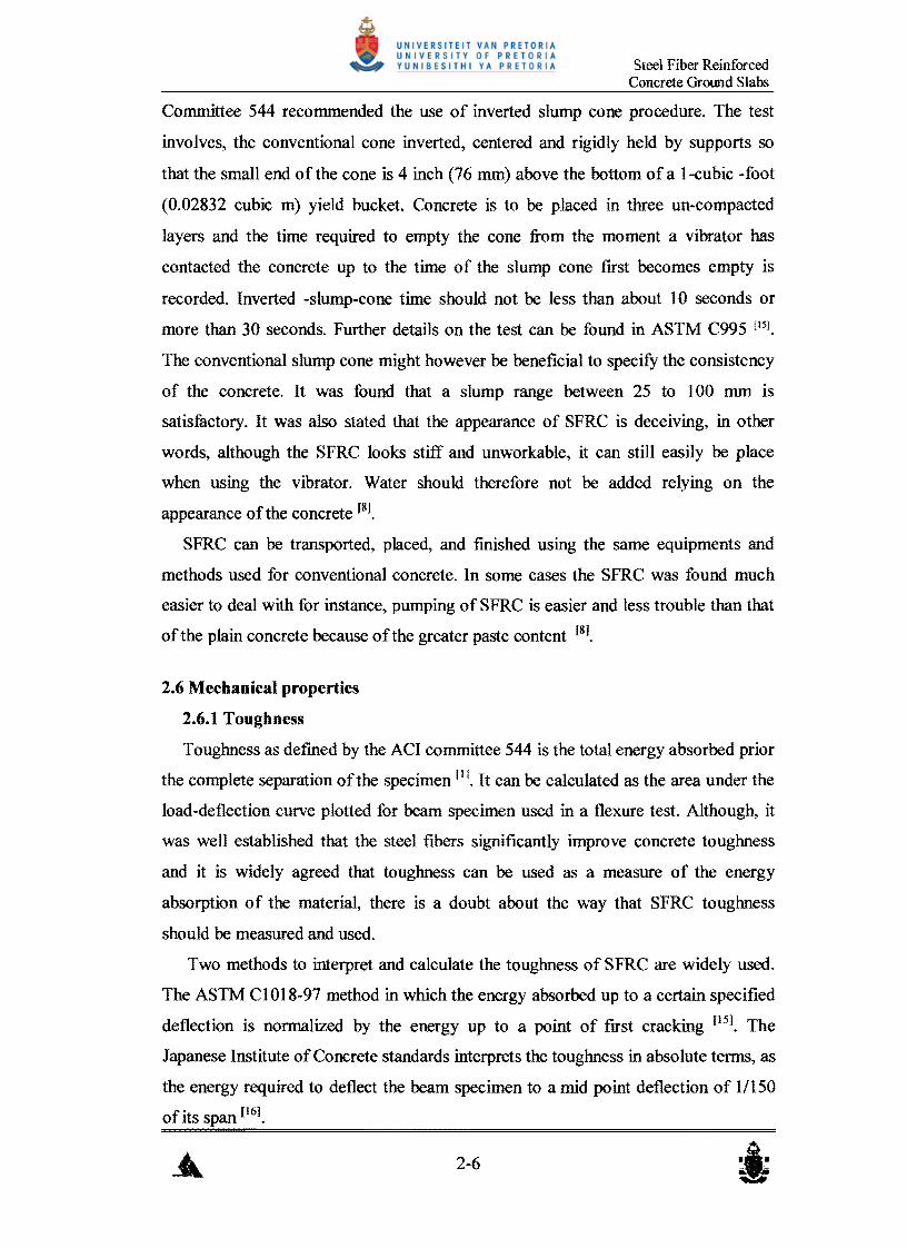
and figure 2-4 to illustrate the American and the Japanese methods respectively.
First Crack
o
IS - AREAoAcoao/AREAoABO 110 .. AREAoAEF80 IAREA OABO 120 .. AREAo...GHuofAREA oABO 130 .. AREAoAlJlO IAREA OABO Iso .. AREA ONl(ooAREA OABO---_..
I
It I
! I I I I I I
: !.,..__ , ____ 4
I: I _ .._---' I
I I I I
! I I
: I I I, I
lJ I
RS,10 - 20C~0· Is'
R,O.2O .. 10(120' 1,0'
R2O,." 10(130' 1m)
R30.SO" SCIso' 1;,0'
K i I I
: ~
1 1 :,,, I I I
: I
: I I
: I
l ! I
Net Midspan Deflection
Figure 2-3: Schematic Diagram Showing (ASTM C1018) Toughness Parameters
(Chen et al)
2-7

Steel Fiber Reinforced Concrete Ground Slabs
A Toughness: TJSCE = AREAOAEFO
Toughness Factor: 2. FJSCE =TJSCE -U(S-H l)t'"
· ! •
I
I ·I ·: · : I · ,· !,
.---------------------------------------------, ! 8 end H are the span, width and height of the beam respectively, :
is deflection of 1{150 of span (2 mm when span is 300 mm). i -----------------------,--------------------~ iF
o Deflection
Figure 2-4: Schematic Diagram Showing the JSCE-SF4 Toughness Parameters
(Chen eta/)
Many criticisms have been directed at the ASTM method. GopaIaratnam et al
carried out an investigation on about 750 beams. Two beam sizes (152x152x533
mm) and (102xl02x356 mm); each with two different types of fibers and two
different fiber contents were used. It was found that the ASTMC 101 8 is not sensitive
to fiber content, fiber type and the size of the specimen. In addition to that the
method is more dependent on the measurement accuracy ofthe deflection. The effect
of the extraneous deformations are found to influence the first crack deflection
significantly and its effect is less for greater values of deflection on the load
deflection curve, therefore an erroneous first crack deflections leads to unreal values
for the area of the curve up to the frrst crack deflection and eventually an error in
measuring the toughness indices. In contrast the JSEC-SF4 approach was found to be
sensitive for the specimen size and fiber type and content, moreover, extraneous
deformation problem is mitigated by considering higher deflection values (1/150 of
the span). The study concluded that the JSCE-SF4 method is more reliable than the
ASTMC1018 and recommendations were made for its usage [171, Chen et al also
came to the same conclusion, they further added that in some cases the frrst crack
point is difficult to determine. Great uncertainty about the shape of the curve in the
2-8

Steel Fiber Reinforced Concrete Ground Slabs
vicinity of the first crack exist, hence indices with in the area (OAEF) as shown in
figure 2-3 is questioned [18].
2.6.2 Flexural strength
The low flexural strength of plain concrete could possibly be over-come by the
addition of steel fibers. A review of the literature on SFRC indicates that in general,
the addition of short, randomly-oriented steel fibers increases the flexural strength of
plain concrete by about 1.5 to 3.0 times, taking into account type and content of the
steel fibers [19] [2] [7].
The tenn flexural strength for SFRC is more complicated compared to that of the
plain concrete. Flexural strength for plain concrete is the stress capacity determined
through a third-point loading test, which strive to fmd the stress at maximum load
that can be sustained by a prismatic beam. The situation is different when speaking
about SFRC due to the after crack toughness imparted by the presence of the steel
fibers. One should distinguish between the different tenns viz, first crack strength,
ultimate strength, and equivalent strength. These terms have different implications to
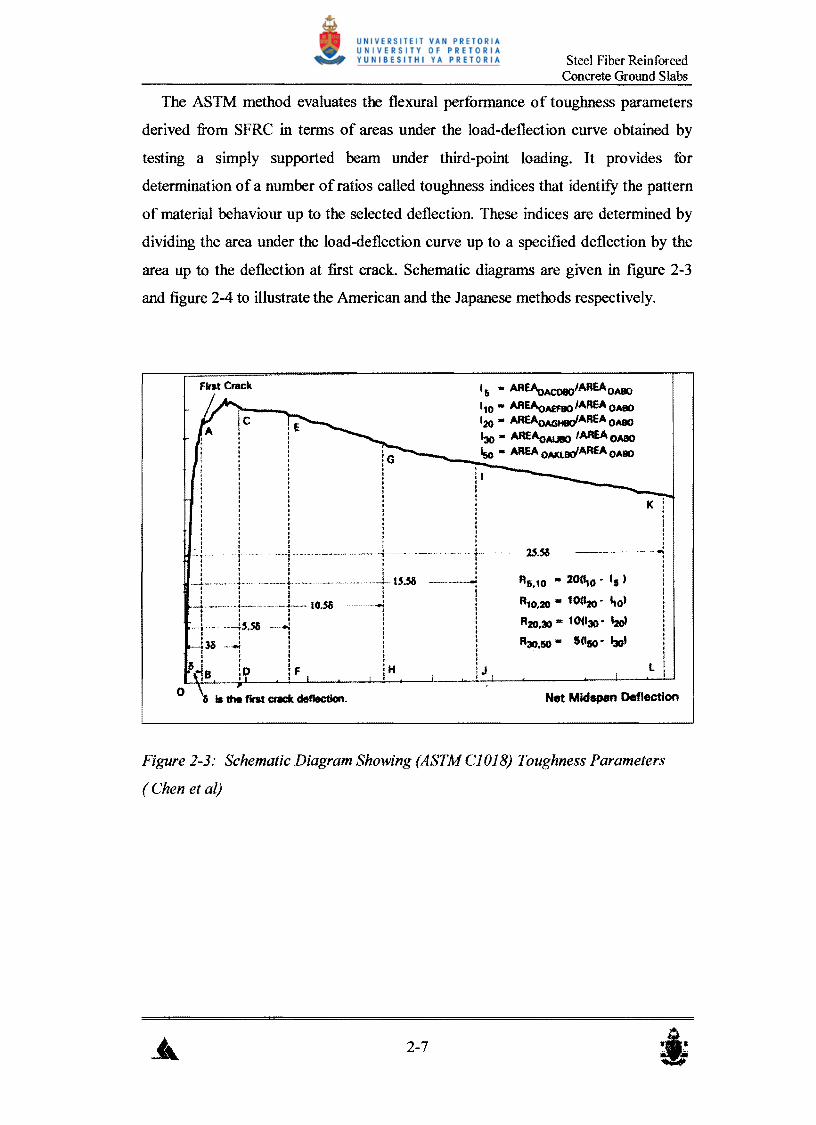
the application of the SFRC and they are indicated in figure 2-5 and defmed as
follows:
[J First crack flexural strength (or some times termed as the proportional
limit): recognized as the stress at point at which the load-deflection
curve first becomes non-linear.
[J Ultimate flexural strength: defmed as the stress at the point of
maximum load that can be sustained during the third-point test.
[J Equivalent flexural strength: It is the stress capacity derived at a point
of specific mean load corresponding to specific deflection in a third
point loading test.
Considering a prismatic beam (150x150x450 mm), the values at a deflection of
(span/300) and (span/I 50) ratios are being adopted; therefore, flexural strengths
corresponding to these deflection values can be successfully used.
2-9
Steel Fiber Reinforced Concrete Grotmd Slabs
FailUftl Load
. :: p Equivalent Load @ 1.5 mm Del.
<e;-- .- .. !"-_ .. _- ----..t"''''--7 · · .,· .· .· · ..· . : : : Po'" Equivalent Load@ 3.0 rom Def.
~- -~--~--------------~--------- -----------~· . .
· · , · , · .... ~
I
Crack L5mm 3.0 mm O.n.ctlon (mm)
Figure 2-5: Schematic Load - Deflection Diagram
Main factors influencing the flexural strength ofSFRC [19] are:
• Degree of consolidation of the matrix, which is a function of water to cement
ratio, consolidation technique, and type and content of the steel fiber.
• Uniformity of fiber distribution, which is mainly influenced by the
workability and mixing procedure used.
• The surface conditions of the steel fibers, which relates to the bond stresses
generated between the steel fibers and the concrete, for instance a hydrophobic
film on the steel fiber surface can prevent the development of an adequate
fiber bond.
Theoretically, the improvement in flexural strength of SFRC is being brought by
the crack arresting mechanism that the steel fiber provides. In fact, the steel fibers
can sustain stress after cracking at strains beyond the normal for failure of plain
concrete. Some sort of stress distribution is promoted which approaches the fully
plastic condition in the tension zone, while remaining elastic in the compression
zone. This mechanism causes the neutral axis of the section to move up, thus, the
moment ofresistance and ultimate load be increased significantly [20].
2-10

Steel Fiber Reinforced Concrete Ground Slabs
Due to the post cracking behavior ofSFRC unlike plain concrete, the total flexural
strength (design flexural strength) is to be taken as the sum ofthe flexural strength up
to the point after which the elasticity zone of the material is exceeded (fIrst crack
strength) and the strength that resulted from the plastic phase (equivalent flexural
strength). Equation 2-1, equation 2-2 and equation 2-3 can be used [II]:
Id = let + le,3 Where:
Id Design Flexural Strength.
let = First Crack Strength.
{" - p *~ .::::=::::> Eq.2-2J e,3 - e,3 bh2
R = 1e,3 *100 ==> Eq. 2-3 e,3 let
h,b = the depth and width of a uniform presmatic beam.
~,3 =Mean Load Over a Deflection of Length/l 50.
2.6.3 Fatigue Endurance
Fatigue endurance could be expressed by the so-called S-N curves, where S is the
ratio of the maximum stress to the statistic strength and N is the number of the cycles
at failure. The maximum value of S below, which no failure occurs, is known as
endurance limit [21]. Previous investigations [22][23] have shown that the relationships
are linear up to at least 2 million cycles; therefore, the term 2-million cycle
endurance limit is commonly used to quantifY the fatigue strength ofSFRC.
Figure 2-6 shows results of fatigue tests conducted by Johnston et al [24] on
prismatic specimens with nine different mixtures and varied fiber parameters (type,
content, and aspect ratio). It was concluded that, the addition of steel fibers has
improved the fatigue endurance of concrete and the improvement ranges between
little and significant depending on the fiber parameters.
2-11

Steel Fiber Reinforced Concrete GroWld Slabs
100 ~'_ ............ -..... - 4 FIBER TYPES I SW - SMOOTH WIRE :§ 1.5 % -..........,"""- " SDW- SURFACE
SW(7!).............. DEFORMED WIRE t 95 -~. ~............ ~ ME -MELT EXTRA g 1,0 % ~ ~ ................ ~ SS -SUT SHEET
til SDW(47~"""" ~ ~ 90 ~ .....~.... ..~ to%SW(75)
i .~'~'" lO% SW (lOO)
: 85'~~-:'''''' 0.5% SW(75)! eo .. "-.... '~'",lO%SS(7n .2 ................ '" 1.0 %i / "-- -........... -<::'ME (54) ~ 75 NO FIBERS lO% SW (50)
Number ofload cycles (N)
Figure 2-6: S-N relationship based on First Crack Strength (Johnston et al)
Hook-ended steel fibers appeared to have a superior influence in the 2 million
cycle endurance limit. An endurance limit of 76% and 80% where found for 0.5%
and 1.0% volumes of hook-ended fibers respectively, whilst, 67% and 59% for
similar volumes ofsHt sheet fibers [23],
The fatigue capacity of plain concrete is generally regarded as equivalent to an
endurance limit equal to 50 to 55% ofthe static modulus of rupture [25], Thus designs
based on half the static strength is appropriate for conventional concrete [26], By
implication either thinner section is required to withstand the same load repetition or
the same thickness could last for longer, and that is key benefit behind the usage of
SFRC.
Bernard et al [27] suggested that fatigue performance for SFRC, expressed as an
endurance limit can conservatively be taken as 65% of the stress to cause the first
crack. Schrader [26] argued that the long term strength gain for SFRC is higher than
that for the plain concrete, therefore, the fatigue performance should be improved as
a result of strength compensation. Eventually it was stated that 85% of the ultimate
strength has the same conservatism, as does 50% for conventional concrete.
2-12

Steel Fiber Reinforced Concrete GroWld Slabs
2.6.4 Impact Strength
Pavements are in many cases subjected to dynamic load either due to the impact
nature of the load itself or due to the high rate ofgradual load applications. Runways
are normally subjected to direct impact loads caused by the landing process and
unevenness of aircrafts while roads are SUbjected to impacts in cases of unevenness,
rutting, artificial bumps, and at faulting joints. It is seldom found that a pavement is
thoroughly subjected to static loads during its useful life, even aprons and container
terminals are subjected to dynamic loads prior to parking of aircrafts or containers
respectively.
Although different type of tests and load application rates were employed by
different researches, it is widely agreed that the addition of steel fibers improves the
impact resistance of concrete. A significant increase was found by using the
pendulum machine; the improvement was being especially favorable with crimped
fibers [21. Tests carried out using the ACI committee technique 1 reported that SFRC
has increased the impact resistance in order of three to four times relative to their un
reinforced counterparts [28] [291• In another set of test carried out on concrete slabs
with and without steel fibers, supported on their edges, a falling weight was
employed from different distanced to represent different energies. The results
showed that the SFRC slabs absorbed about 4 times the impact energy of the plain
concrete for equivalent damage [301•
Gopalaratnam et al [311 and Banthia et al [32], both came to conclusion that, the
impact data is mostly sensitive to the stress-rate, in other words for different stress
rates there are different values for the impact strength. It was also agreed that the
higher the rate of the load application the higher the impact resistance for both plain
and SFRC, that can be seen from figure 2-6.
1 The test involves dropping of 10 lb soil compaction hammer 18 inches onto a hardened steel ball placed in the center ofthe concrete specimen, whieh measures 6 inches in diameter and 2.5 inches thick. The nwnber ofblows required to crack the material is used to quantifY the impact resistance of concrete
2-13

Steel Fiber Reinforced Concrete Ground Slabs
2.5
FIBER VOI.UME FRACTION
Iii 1.5 ". ~~ 20 1.0%e;
0.5%
33 PI.AIN MORT,1.R.J.J
!! 1.5 II.Q,
0
i % LOto
! STRAIN RATE, e(1/$)
Figure 2-7: Effect olStrain-Rate and Fiber Content on Flexural Strength
(Gopalaratnam et al)
It is apparent from the above discussion that SFRC flexural strengths gained from
relatively static load type of tests are less than those obtained from increased stress
rate tests. Designs based on static strengths are therefore satisfactory and safe.
2.6.5 Compressive strength
It has been found by many researchers that the inclusion of steel fiber in concrete
increases it is compressive strength value relative to the fiber content. Their fmdings
ranged between marginal and significant increases in compressive strength.
Experimental work conducted in India, using straight steel fiber (LID = 46/0.91
mm) and fiber content ranges between (0 and 3% by volume) found that, significant
increase in compressive strength is achieved (about 40% increase when using 3%
fiber content). More over, test results have shown a linear relation between the fiber
content and the compressive strength of the concrete if fiber is being added. The
following empirical equation was generated [33].
2-14

Steel Fiber Reinforced Concrete GrOl.md Slabs
c=::::> Eq.2-4
Where:
:= Compressi~ strengthof theSFRC. Ff
F.: := Compressi~ strengthof the parent concrete.
K, = Empiricalconstant( 0.123).
P :=Percentagmfsteelfiber( by volume)
a = Amplification factor.
Tests in Australia showed that, the addition of steel fiber to concrete matrix may
produce marginal gains in compressive strength at constant water cement ratio. At
steel fiber concentrations of (50 to 90 kg/m3) the increase in compressive strength is
not usually statistically discernible [30],
Tests, on SFRC cubes made from same mix and containing bent fiber, carried out
at the CSIR (South Africa), revealed that the addition of steel fibers with various
contents may increase the compressive strength slightly (approximately 10%) and the
highest increase occurred at low steel fiber contents (up to 20 kg/m3), In addition of
that, specific limits exist after which a reduction or less increase on compressive
strength is expected with addition of more steel fibers, In other words an excessive
increase of fiber content will not affect the compressive strength as prior to that limit.
This confirms that the addition ofsteel fibers is not a cost effective way of improving
the compressive strength ofconcrete [34],
Results from cubes and cylinders tested in compression might differ significantly
because the vibration tends to align the fibers in certain planes. In cylinders they tend
to align perpendicular to the axis of loading where they could help to inhibit lateral
bursting, while in cubes they tend to align parallel to the axis of loading [20].
According to Edgington et al, fibers in SFRC compacted by means of table
vibration have a tendency to align themselves in planes at right angles to the
direction of vibration. This indicates, that the method of compaction can be an
important parameter influencing the compressive strengthofSFRC [2],
Perrie argued that, since the failure is initially due to breakdown at the aggregate
interface, fibers are expected to have little effect on compressive strength of concrete [20]

Steel Fiber Reinforced Concrete Ground Slabs
The author's opinion is that, the influence of steel fiber on the compressive
strength should be taken as insignificant and the increase in compressive strength
developed as the result of the presence of steel fibers should be considered to
compensate for the variation of the testing results due to variation of fiber orientation
and content in different specimens. Thus, the compressive strength of the parent
plain mix should be considered as the target compressive strength.
2.6.6 Shear strength
Steel fibers are found to increase the shear capacity of concrete significantly [35]
[36]. It was found that the inclusion of 1% by volume ofhook-ended steel fibers could
increase the shear strength of the SFRC by about 144% to 210% relative to the plain
concrete depending on the aspect ratio of the steel fibers [37]. Punching shear tests
show that the addition of 75 kglm3 of steel fibers with enlarged ends increase the
punching resistance by about 51 % in comparison to plain concrete [30]. The mode of
failure is also found to be changed due to the extra-enhanced shear capacity. Ductile
failure was experienced instead of sudden diagonal failure [36] and in some cases the
mode of failure changed from shear failure to a moment failure [37].
Shear strength capacity is important for pavements. Comer and edge break-off
might occur as the resuh ofexceeding the shear capacity ofconcrete; storage racking
or raised storage legs can also punch on the floor. The knowledge of the shear
capacity and behaviour of materials should therefore be applied to pavements.
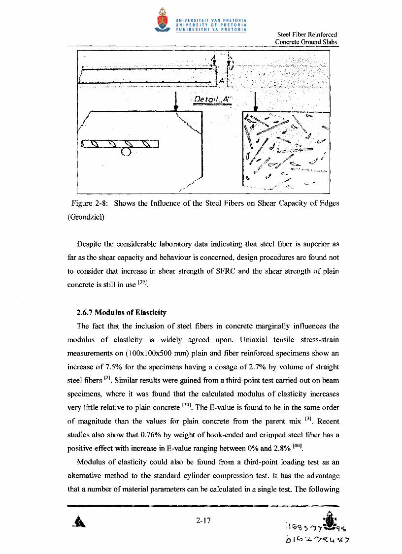
Grondziel [38] state that using SFRC at Frankfurt International Airport has virtually
eliminated the joint shear failure due to its homogeneity and increased shear strength.
He gave the model as shown in figure 2-7 to illustrate the benefit of using SFRC
instead ofconventionally reinforced concrete.
2-16
Steel Fiber Reinforced Concrete Ground Slabs
!I.
Figure 2-8: Shows the Influence of the Steel Fibers on Shear Capacity of Edges
(Grondziel)
Despite the considerable laboratory data indicating that steel fiber is superior as
far as the shear capacity and behaviour is concerned, design procedures are found not
to consider that increase in shear strength of SFRC and the shear strength of plain
concrete is still in use [391.
2.6.7 Modulus of Elasticity
The fact that the inclusion of steel fibers in concrete marginally influences the
modulus of elasticity is widely agreed upon. Uniaxial tensile stress-strain
measurements on (100xlOOx500 mm) plain and fiber reinforced specimens show an
increase of 7.5% for the specimens having a dosage of 2.7% by volume of straight
steel fibers [21. Similar results were gained from a third-point test carried out on beam
specimens, where it was found that the calculated modulus of elasticity increases
very little relative to plain concrete [301. The E-value is found to be in the same order
of magnitude than the values for plain concrete from the parent mix [31. Recent
studies also show that 0.76% by weight of hook-ended and crimped steel fiber has a
positive effect with increase in E-value ranging between 0% and 2.8% [40].
Modulus of elasticity could also be found from a third-point loading test as an
alternative method to the standard cylinder compression test. It has the advantage
that a number ofmaterial parameters can be calculated in a single test. The fo llowing
2-17 I~' i110 <n S"1 "r \II'f1.
hI r;o '2 "7<ll+ <3: /'
Steel Fiber Reinforced Concrete Ground Slabs
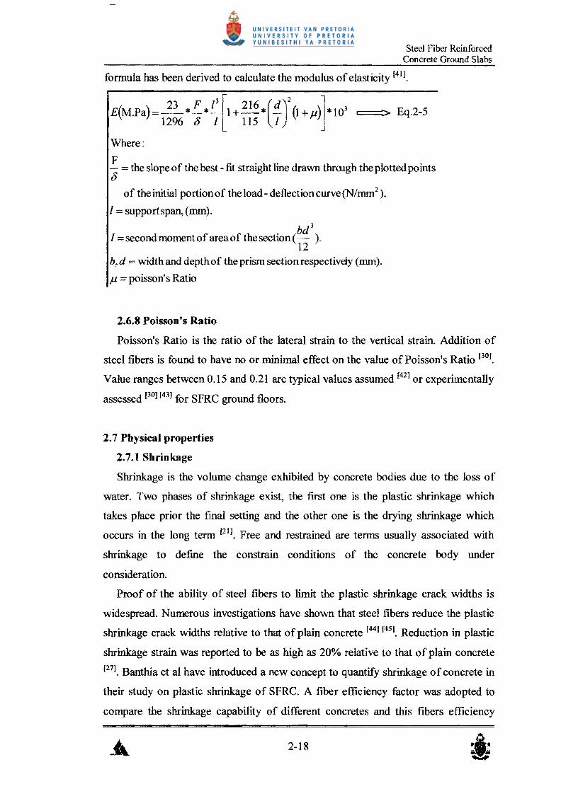
formula has been derived to calculate the modulus ofelasticity [41].
E(M.Pa)=~* F *~[1+ 216*(d)2 (1 +.u)l *103 ====:> Eq.2-S1296 g I lIS I J
Where:
F = the slope of the best -fit straight line drawn thrrugh the plotted points g
of the initial portion of the load - deflection curve (N/mm2).
1= support span, (mm).
bd3
I = second moment of area of the section (- ).12
b, d =width and depth of the prism section respectivdy (mm) .
.u poisson'sRatio
2.6.8 Poisson's Ratio
Poisson's Ratio is the ratio of the lateral strain to the vertical strain. Addition of
steel fibers is found to have no or minimal effect on the value of Poisson's Ratio [301.
Value ranges between O.IS and 0.21 are typical values assumed [42] or experimentally
assessed [30] [43] for SFRC ground floors.
2.7 Physical properties
2.7.1 Shrinkage
Shrinkage is the volume change exhibited by concrete bodies due to the loss of
water. Two phases of shrinkage exist, the first one is the plastic shrinkage which
takes place prior the fmal setting and the other one is the drying shrinkage which
occurs in the long term [21]. Free and restrained are terms usually associated with
shrinkage to defme the constrain conditions of the concrete body under
consideration.
Proof of the ability of steel fibers to limit the plastic shrinkage crack widths is
widespread. Numerous investigations have shown that steel fibers reduce the plastic
shrinkage crack widths relative to that of plain concrete [441 [45], Reduction in plastic
shrinkage strain was reported to be as high as 20% relative to that of plain concrete
[27]. Banthia et al have introduced a new concept to quantify shrinkage ofconcrete in
their study on plastic shrinkage of SFRC. A fiber efficiency factor was adopted to
compare the shrinkage capability of different concretes and this fibers efficiency
2-18

Steel Fiber Reinforced Concrete Ground Slabs
coefficient can be calculated as follows:
Fiber Efficiency Factor == Le /W ===::> Eq.2-6
Where
Le = Cumulative crack length.
W Cumulative crack width in the area under consideration
They further found the addition of 0.75 % by volume of crimped steel fibers will
result in an effectiveness factor of 146.6 and 8 cracks while plain concrete yielded an
effectiveness factor of 14.03 and one crack which proves that steel fibers can
distribute cracks more evenly over the entire length resulting in closely spaced
reduced widths cracks [44].
Drying shrinkage strain is of considerable importance to pavement applications
because it has a direct contribution to the spacing of the joints. There are conflicting
evidences regarding the effectiveness of steel fibers in limiting both free and
restrained drying shrinkage strain in SFRC. Edgington et al [2] found that the
shrinkage of concrete over a period of three months was unaffected by the presence
of the straight steel fibers used. A study by Grzybowski et al [46] found that steel
fibers does not alter the free drying shrinkage properties of concrete, in the other
hand many later investigations have proven that the steel fibers have a significant
effect in improving the restrained shrinkage properties ofconcrete [47] [48] [49].
Work was conducted by Chern et al [47] (on both beams and cylindrical specimens
having crimped and straight steel fibers) to study the influence of steel fiber
parameters testing age and ratio of the specimen volume to the exposed surface on
shrinkage characteristics of concrete. It was found that, steel fibers restrain
deformations more effectively at later ages due to the development of higher
interfacial bond strength between fiber~ and matrix. Therefore, the older the SFRC
the less shrinkage strains. It was also evident that both higher fiber content and
aspect ratio was found to yield less shrinkage than those oflower values.
Despite the efforts directed towards developing a test method to examme
shrinkage of slabs, which is more applicable to pavements, no published evidence
exists that any substantive tests have been undertaken to quantify drying shrinkage
strain in SFRC slabs. Most of the investigations mentioned, employed a ring or beam
specimens with, at best, indirect relevance to concrete slabs, as the small cross
2-19

Steel Fiber Reinforced Concrete Ground Slabs
sectional dimensions of the shrinkage moulds can result in preferential alignment of
steel fibers in the direction of measured shrinkage. Standard size shrinkage
specimens may therefore exhibit strains that are far different from the reality at
which fibers are randomly oriented [27].
Literature on shrinkage provides different theoretical models to assess the plastic
shrinkage strain [45], and crack spacing and widths resulting from drying shrinkage of
SFRC [46] [50]. The author's view is that, these models should not be applied to
pavements because of the above-mentioned reasons. Further work on shrinkage of
slabs should be conducted.
2.7.2 Creep
Creep is the long-term deformation that a material exhibits under the application
ofa sustained load. Reasons for the concrete to creep are related to the movement of
water out of the cement paste and more over, due to the prorogation of micro-cracks [21]
Creep studies in compression have been carried out at a number of applied stress
strength ratios ranging between 0.3 to 0.9 using cement paste, mortar and concrete
mixes. Melt extract and hooked fibers with volume contents ranging between 0 and
3% (about 0 and 235 kg/m3) were added to the mixes that were used to cast prismatic
specimens (150xI50x500mm). The results after 90 days loading and 60 days
unloading indicate that steel fibers have a significant (ranges between 15 and 24%
reduction) influence in restraining the creep of specimens under uniaxial
compression. More over, it was reported that, the restraint provided by steel fiber to
the creep becomes more pronounced with increasing time under load [51].
Contradictory results were obtained on compressive creep test on concrete
specimens having straight fibers with volumes ranging between 0 and 1.47 % (0 to
1] 5 kglm3). Specimens were loaded over 12 months. The results concluded that the
effect ofsteel fibers on creep strains is negligible [2].
Flexural creep test on SFRC (75 kglm3 enlarged end steel fibers) specimens
(stress - strength ratios of 0.43 and 0.69), shows that the flexural creep is
considerably less than for the identical concrete without steel fiber. The reported
ratio of creep strain to load strain for plain concrete after 518 days loading was
around 25% higher than for steel fiber reinforced concrete [30],
2-20

Steel Fiber Reinforced Concrete Ground Slabs
Another series of tests on flexural creep shows that creep strains are much less in
the compression zone of a specimen than in tension zone [49]. Typically, with 1%
percent by volume (about 78 kg/m3) steel fibers and t1exural stress-strength ratio of
0.35, creep strains in the tension zone of the specimens ranged between 50 to 60% of
the strains in the plain concrete specimens. The creep strains in the compression zone
ofthe steel fiber specimens were 10 to 20% ofthe plain concrete specimens.
It can be seen that, the steel fibers has a negligible effect when low fiber content is
added while a significant improvement is gained with larger amount ofsteel fibers. It
should also be noted that flexural creep is more important than compression creep for
ground slabs.
2.7.3 Durability
Porosity and permeability are primary factors affecting the durability of the
concrete due to it's effect on alkali-acid reaction, leaching characteristics, resistance
to chloride or sulphate attack, reinforcement corrosion, and freezing and thawing
characteristics [7], Initially SFRC mixes had high porosities and permeabilities due to
the higher W/C used to increase the workability. Recently, reductions in W/C ratio
are possible, which result in relatively low porosities and permeabilities. Tests
indicated that the SFRC has permeability values typical of those for the plain
concrete [30J, therefore, apart from corrosion of steel fibers, the SFRC has the same
durability (if not better) than the identical plain concrete.
Attention has to be given to the question of the corrosion of the steel fibers when
added to concrete. Theoretically, one ofthe main problems associated with the use of
steel fibers is their durability in concrete structures. In severe exposure condition,
corrosion of steel fibers is more aggravated than that of steel bars, in other words, a
significant decrease to the steel fibers diameter, contribute significantly to lessen the
load capacity ofthe structure at service [52]. In contrast, unlike steel bars, only limited
expansion force develops due to the corrosion of steel fibers [14], which means less
paste disruption and eventually minimal breakdown and weathering rates in
comparison to conventional concrete reinforced by steel bars [27].
There is ample evidence that in practice, in good quality concrete, fibers corrosion
does not penetrate into the concrete. Laboratory studies have shown that, stainless
steel fibers can perform well even in a very aggressive type of exposure conditions
2-21
Steel Fiber Reinforced Concrete Groood Slabs
while the carbon steel fibers invite the corrosion and cracks development [53]. SFRC
specimens exposed to a marine environment for about 10 years, show that the
corrosion of fibers is limited to the surface of the un·cracked specimens and no
noticeable reduction in flexural strength was found, whilst, for cracked specimens,
corrosion does occur through the depth of the crack and reduction on flexural
strengths were encountered [54J.
Under normal fmishing processes very few fibers will be left exposed at the
surface of slabs and any such fibers exposed to the surface is assumed to corrode and
blow away under trafficking [39]. Schupack found that the corrosion depth is usually
confmed to the first 5 mm [54], therefore, designs should consider cover depths of
about 10 mm apart from recommending the knocking down of steel fibers while
fmishing the concrete surface.
2.7.4 Abrasion and Skid Resistance
Knowledge of abrasion and wear resistance of concrete is essential especially for
pavement due to the continuous nature of its loads. Difficulties might be encountered
concerning of the wear and abrasion resistance, as the damaging action varies
depending on the cause of wear, and no single test procedure is satisfactory in
evaluating the resistance ofconcrete to the various conditions ofwear [21].
Tests on hydraulic structures, which have the same effect of wear on slabs under
traffic loads, revealed that the abrasion resistance ofSFRC is not improved over that
of the plain concrete [1]. Significant increases of abrasion resistance was found by
other researchers, with about 15% higher resistance reported under drying, wet and
frozen surface conditions [391. Tests carried out to compare the abrasion resistance of
plain concrete specimens (25 MPa) and SFRC having 75 kg/m3 enlarged end type of
fibers, reported that the SFRC specimens have a LA (Los Angeles abrasion wearing
test value: it includes milling specimens in the presence of steel and concrete balls
for a certain number of revolutions. LA is the increase in the percentage of the
material passing the 1.7 mm sieve) value of 50% greater than that of plain concrete
specimens [30], which in turn proves the capability of steel fibers to resist abrasion
and wear.
Wear tests were carried out using a pair of hardened steel wheels running in a
circular path under load on flat specimen slabs. It was found that for specific number
2·22

Steel Fiber Reinforced Concrete Ground Slabs
of cycles, the SFRC exhibits average groove depths less than that of plain concrete,
which in turn proves that the SFRC has a better wear resistance relative to an
identical plain concrete [30].
The skid resistance of SFRC was found to be same as that ofthe plain concrete at
early stages prior the deterioration of the surface. In later stages, where abrasion and
erosion of the surface had to taken place, steel fiber reinforced concrete has an up to
15 % higher skid resistance relative to plain concrete [I].
It can be concluded that the SFRC has better performance regarding its erosion,
abrasion and skid resistance, but how much better is dependent on the case of
application.
2.7.5 Thermal Properties
There are three thermal properties that may be significant in the performance of
concrete, viz, coefficient of thermal expansion, specific heat and conductivity [21]. To
the author's knowledge little work on SFRC has been done in this area.
Thermal expansion is seen to be the most relevant to the ground slabs applications
especially for concrete subjected to thawing and freezing action. Specific heat and
conductivity are normally relative to applications whereby thermal insulations are
provided [21], or other applications such as rocket launch facilities or mass structures [55]
The effect of steel fibers on coefficient of expansion factor was studied using
beam specimens that have various steel fibers content (ranges between 0 and 2 % by
volume). Specimens were subjected to temperatures ranges between 38 and 66
degree Celsius. Tests results indicate that the coefficient of thermal expansion factor
was not significantly affected by fiber content [3]. Tests on relatively dry SFRC
specimens at ages of about 220 to 250 days and 27 degree Celsius temperature rise,
revealed that addition of steel fibers marginally influence the thermal expansion
coefficient. Just to give an indication, for SFRC containing 75 kglm3 of enlarged-end
steel fibers, the typical expansion coefficient is found to be 8.2 x 10⁻⁶ per degree
Celsius [30].
Thermal conductivity of SFRC is studied by Cook et al [55], they found that an
increase of25 % to 50% in thermal conductivity could be achieved with specimens
2-23

Steel Fiber Reinforeed Concrete Ground Slabs
having straight steel fiber contents of I % and 2%. Another contradictory study
reported that with 0.5% to 1.5% by volume steel fiber, a small increase in thermal
conductivity could be obtained [1].
It can be seen from the above discussion that the expansion of SFRC is the same
(if not less) than plain concrete for identical mixes. The author's opinion is that, the
only hazard is the expansion coefficient of the steel fibers, in other words, large
differences between thermal coefficients of steel fibers and paste might cause the
interface layers between them to damage and damage in many surfaces in different
dimensions might weaken the entire matrix.
2.7.6 Electrical Conductivity
Steel fibers contents of up to 1 % by volume (80 kg/m3) has no significant effect
on electrical conductivity [30J [39J, hence, wire guided vehicles may be operated
without difficulties on SFRC floors, which can be taken as an advantage if compared
with steel bars or mesh floors [39J. It can also be beneficial where traffic devices are
needed e.g. vehicle detection loops for traffic counting and classification.
2.8 Conclusion
The following conclusions are drawn
Q Although different types of steel fibers have been used, hook-ended steel
fibers were found to perform better than the other types because of its
hooked ends and! or high tensile strength, which requires additional loads
for pulling out and lor breaking.
Q The mechanistic mix proportioning design approach for SFRC strives to
adjust the additional paste required to coat the added steel fibers, therefore
a some sort of coupling concept can be used, in other words, any of the
plain concrete proportioning mix criterion can be used to design the mix
and there after the mix can be adjusted for the added fibers.
Q The normal transporting, placing and finishing methods used for plain
concrete can also used for SFRC.
Q Steel fiber has an effect ranging between little and significant on the
mechanical properties. Endurance limit, impact strength and shear strength
2-24

Steel Fiber Reinforced Concrete GrOWld Slabs
are significantly improved while compressive strength, modulus of
elasticity and Poisson's ratio improve slightly when the steel fiber is
added. The flexural strength at fIrst crack and maximum load is slightly
improved, but on the other hand, the imparted toughness improves the
equivalent strength ( after crack) significantly (as high as 100%).
a The physical properties are also altered by the use ofsteel fibers. The steel
fibers have a significant effect on the plastic shrinkage while little effect is
found for the drying shrinkage. Methods used to measure the shrinkage are
found not to simulate pavements. Creep is significantly influenced when
using high dosage of steel fiber while little effect is found with low steel
fiber dosages. The abrasion and skid resistance are also improved
significantly. A negligible effect is found on the electrical conductivity.
The thermal properties of the SFRC are not properly established and
problems could be encountered as a result of the wide difference between
the thermal expansion factor for the steel fiber and the other mixture
constituents. Durability is not influenced by the use ofsteel fibers.
2-25