![1 t!]äfertuning.de/static/Legends_TR_SE_OCR.pdf · 2013. 4. 23. · pumps & cylinders actuators & control control v alve control valve miscellaneous miscellaneous name symbol description](https://static.fdocuments.us/doc/165x107/6086a882744a0a058773f937/1-t-2013-4-23-pumps-cylinders-actuators-control-control-v.jpg)
Chapter 2 PUMPS AND ACTUATORS Marks 12
16
Chapter – 2 PUMPS AND ACTUATORS Marks – 12 A basic hydraulic system consists of following major components 1. Reservoir – an oil supply tank 2. Pump & Prime mover – the source of power 3. Pressure relief valve – for system safety 4. Control Valves – for direction & other controls 5. Cylinder / Hydro motor – the working element Though each of the items plays an important role in the system, pump has a specific and unique position in the system. It can be compared to the heart of a human being. The main purpose of the pump is to create the flow of oil through the system and thus assist transfer of power and motion. The pump is coupled to and driven by the prime mover of the system, which is most often an electric motor. The inlet side of them pump is connected to the reservoir and the outlet or pressure side to the control valve and thus to the rest of the system. Classification of Pumps – Basically pumps are classified as Positive and non-positive pumps. Positive Displacement Pumps (PD) – Positive Displacement Pumps are those whose pumping volume changes from maximum to minimum during each pumping cycle. That is, the pumping element expands from a small to large volume and is then contracted to a small volume again. PD pumps are used where pressure is the primary consideration. In these pumps the high and low pressure areas are separated so that the fluid can not leak back and return to the low pressure source. As fluid moves through the pumping chamber, volume increases and is finally reduced causing it to be expelled. Gear, vane, piston, screw pumps are the examples of such pumps. In such pumps the flow enters and leaves the unit at the same velocity, therefore practically no change in kinetic energy takes place. These are also known as hydrostatic power generators. Advantages of PD pumps – 1. They can generate high pressure. 2. They are relatively small and have high power to weight ratio. 3. They have relatively high volumetric efficiency. 4. They have greater flexibility of performance under varying speed and pressure requirements.
Transcript of Chapter 2 PUMPS AND ACTUATORS Marks 12
Chapter – 2 PUMPS AND ACTUATORS
Marks – 12
A basic hydraulic system consists of following major components
1. Reservoir – an oil supply tank
2. Pump & Prime mover – the source of power
3. Pressure relief valve – for system safety
4. Control Valves – for direction & other controls
5. Cylinder / Hydro motor – the working element
Though each of the items plays an important role in the system, pump has a specific and
unique position in the system. It can be compared to the heart of a human being. The main
purpose of the pump is to create the flow of oil through the system and thus assist transfer of
power and motion.
The pump is coupled to and driven by the prime mover of the system, which is most often an
electric motor. The inlet side of them pump is connected to the reservoir and the outlet or
pressure side to the control valve and thus to the rest of the system.
Classification of Pumps –
Basically pumps are classified as Positive and non-positive pumps.
Positive Displacement Pumps (PD) –
Positive Displacement Pumps are those whose pumping volume changes from maximum to
minimum during each pumping cycle. That is, the pumping element expands from a small to
large volume and is then contracted to a small volume again.
PD pumps are used where pressure is the primary consideration.
In these pumps the high and low pressure areas are separated so that the fluid can not leak
back and return to the low pressure source.
As fluid moves through the pumping chamber, volume increases and is finally reduced
causing it to be expelled.
Gear, vane, piston, screw pumps are the examples of such pumps.
In such pumps the flow enters and leaves the unit at the same velocity, therefore practically
no change in kinetic energy takes place.
These are also known as hydrostatic power generators.
Advantages of PD pumps –
1. They can generate high pressure.
2. They are relatively small and have high power to weight ratio.
3. They have relatively high volumetric efficiency.
4. They have greater flexibility of performance under varying speed and pressure
requirements.

Non-Positive Displacement Pumps (NPD) –
Pumps where the fluid can be displaced and transferred using the inertia of the fluid in motion
are called as Non Positive Displacement Pumps. Examples of NPD are centrifugal pumps,
propeller pumps etc.
They are usually used for low pressure (upto 40 bar) and high volume system. Because of
their fewer number of moving parts, NPD pumps cost less and operate with less
maintenance.
The chamber of NPD pumps is connected so that as pressure increases, fluid within the
pumping chamber circulates.
These pumps make use of Newton’s first law of motion to move the fluid against system
resistance. The action of the mechanical drive in the pumping chamber speeds up the fluid so
that its velocity increases.
Advantages of NPD –
1. There is low initial cost.
2. Maintenance cost is minimum.
3. They can be operated quietly.
4. They are capable of handling almost any type of fluid for example sludge or slurries.
5. They have simplicity in operation.
6. High reliability.
Since the inlet and outlet passages are connected hydraulically, centrifugal pumps are not
self-priming and must be positioned below the fluid level.
Construction & working of Positive Displacement Pump
As defined earlier a PD pump
1. Has to generate continuous flow of liquid and also
2. Has to supply necessary force (pressure) to the flow of liquid.
PD pumps can be either reciprocating or rotary type.
These pumps can also be divided as
a. Fixed displacement i.e. pumps with constant delivery in which flow of volume is
constant when the speed is constant. These pumps have no control on rate of flow.
b. Variable displacement pumps where the output volume i.e. the flow rate of pump is
variable.
Reciprocating pump – These are generally cylinders with piston operating as a pump. They
are available in various sizes, shapes and driving mechanisms.
Rotary pump – They are most common in oil hydraulics when low to medium pressure is the
prime consideration.

Gear Pumps –
External Gear Pump -
The basic gear pump consists of two meshed gears, a case or housing to encompass the
gears and two cover plates that enclose the ends of the gears.
Each gear is mounted on the shaft which is supported on bearings in the end covers. One of
these shafts called drive shaft is coupled to the prime mover i.e. the motor. Two ports, inlet
and delivery are provided.
Operation / Pumping action –
A tooth space of one gear is filled with tooth space of other gear. As the meshed gears start
rotating one tooth space after the other is evacuated and in the resulting spaces a vacuum is
created.
Atmospheric pressure in the tank forces the oil onto the tooth space from the inlet port. This
tooth space filled with oil is carried around the periphery of the gear until the teeth again mesh
and the oil is forced out of the space by meshing tooth and flows ou of the delivery port. Thus
the pump dispels one toothfull of oil per tooth per revolution.
Close fitting of the covers and other parts prevent leakage of oil through the mating parts. The
pressure developed by the pump depends upon the load on the system.
Internal Gear Pump –
Internal gear pumps work on the similar principle as that of external GP but differs in
construction.
The internal spur ear drives the outside ring gear which is set off-centre (eccentric) to each
other. Between the two gears on one side there is a crescent shaped spacer which is a
stationary part of the housing around which oil is carried. The inlet & outlet ports are located
in the end plates between where the gear teeth mesh and unmesh at the two ends of the
crescent shaped spacer.

Operation –
The internal gear drives the external gear and affects a fluid tight seal at the place where the
teeth start meshing.
Rotation causes the teeth to unmesh near the inlet port, the cavity volume increases and
suction occurs.
Oil is trapped between the internal and external gear teeth on both sides of the crescent-
shaped spacer and is carried from inlet to outlet port of the pump.
Meshing of the gear teeth reduces the volume in the high pressure cavity near the outlet port
and oil exits from the outlet port.
Gearotor Pump –
Gerotor pump resembles the internal gear pumps. The main parts of the gerotor pump
consists of Outer ring, Outer gerotor, Inner gearotor.
The inner gerotor is the driver and the outer is idler. There is only one shaft involved which
means a certain simplification in design. The number of inner and outer gerotor varies in
number wherein the outer gerotor has always one tooth more.
The axis around which the inner element rotates is offset from the axis of the outer gerotor. If
the number of teeth for the inner and outer gerotor are 4 & 5 respectively, while the inner
gerotor makes one revolution, the outer one makes 4/5 or 0.8 revolution.
They are primarily suitable for clean, low pressure applications such as lubrication systems or
hot oil filtration systems, but can also be found in low to moderate pressure
hydraulic applications.
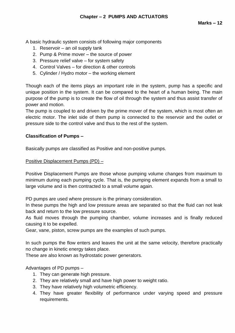
Unbalanced Vane Pump –
In Unbalanced Vane Pump, the rotor axis is positioned eccentric to the circular ring inside
which it rotates
.Since the vanes are free to slide in their slots, they move outward due to centrifugal force
and spring pressure.
As the vane makes contact with inner ring wall, a positive seal takes place between the vane
tip and the cam ring.
Thus a number of chambers are formed between the vanes and cam ring. The chamber
changes their volume continuously because the vanes follow the inner contour of the ring.
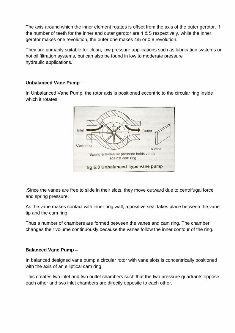
Balanced Vane Pump –
In balanced designed vane pump a circular rotor with vane slots is concentrically positioned
with the axis of an elliptical cam ring.
This creates two inlet and two outlet chambers such that the two pressure quadrants oppose
each other and two inlet chambers are directly opposite to each other.
Therefore the forces acting on the shaft are fully balanced and side loading is eliminated.
In actual design the two inlet ports are connected to each other and so are the two outlet
ports so that in pump housing there is only one pump inlet and one delivery port.
These types of pumps are fixed displacement pumps.
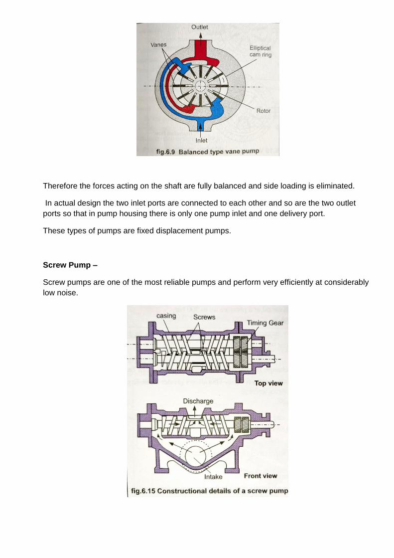
Screw Pump –
Screw pumps are one of the most reliable pumps and perform very efficiently at considerably
low noise.

These pumps transfer fluid by displacing the oil axially through a closely fitted chamber
formed between the screw recess and housing wall. They are fixed displacement pumps and
generally flow rate can be varied by varying the drive motor speed.
The only moving parts are the screws. A two element rotary type screw pumps is shown in
figure. Mostly they are available as one, two or three screw designs.
In the screw pump with two screws, timing gears are required to maintain a running clearance
between the two meshing screws. Each of the two screws have half left hand threading and
half right hand threading. These screws mesh to form a fluid tight seal between the screws
and screws and casing.
Out of the two screws, one is connected to the drive shaft and another is driven by gears. As
the screws rotate, they draw oil from the suction chamber and enfold into the helical grooves.
As the screw further rotates the fluid gets transferred along the screw linearly and finally
forced into the delivery chamber
Radial Piston Pump –
Radial piston pump has a fixed casing incorporating suction and delivery ports in it.
Inside the casing there is a rotating piston block which carries the pistons and at the center
there is a fixed eccentric cam, whose center and center of rotation of the block are offset to
eachother.
As the piston block rotates in clockwise direction, the eccentricity causes the pistons on the
suction side to move inwards and pistons on delivery side to move outwards.
This motion of pistons causes suction and delivery of the fluid. The flow of direction of the
pump is decided by the direction of rotation.

Swash plate type axial piston pump –
Swash plate type axial piston pump consists of a rotating cylinder barrel which consists of
pistons arranged on it axially. The piston ends are connected to an inclined swash plate.
The direction of piston movement (forward and backward) is decided by its peripheral position
on swash plate
The rotating piston travels along the elliptical line on the stationary swash plate. As the
cylinder barrel is rotated, the piston shoe follows the surface of the swash plate.
Since the swash plate is at an angle, the piston has to reciprocate within the cylinder bore
and thus oil is sucked during one half of the circle of rotation and during the other half of
rotation, the oil is forced out of the delivery port.
The delivery of this type of pump can be varied or reversed by changing the swash plate
angle.
Selection Criteria of Hydraulic Pump –
1. Pressure –
Pressure is a fundamental pump selection factor. It is generally limited by the capability of the
pump to with stand pressure without undesirable increase in internal leakage or without
damaging the pump parts.
In general for higher pressures, piston type of pumps is the natural choice.
Screw and vane pumps are very efficient in low pressure application whereas external gear
pumps are used for very low to moderate pressure systems.
2. Flow rate –
Pumps have to generate hydraulic power and also supply a volume of oil at a certain
pressure to the system. Theoretically pump volume can be calculated as –
i. Qth = i.v.n
where, Qth - Theoretical flow rate
i – number of chambers inside the pump
v – volume of each chamber
n – pump rpm
The flow rate capacity of any pump depends on two factors –the geometric size of the
pumping chamber and the rotational speed of the pump.
3. Efficiency –
There are three efficiencies namely volumetric, mechanical and overall
Volumetric efficiency is the ratio of actual delivery to theoretical delivery.
Mechanical eff is determined by dividing the theoretical torque required to drive it by
the actual torque required to drive it and
Overall efficiency is the product of mechanical eff and volumetric eff.
4. Fluid compatibility –
This is one more consideration in the selection of pump.Sometimes if the fluid is not
compatible it may cause damage to the seals and leakage may occur resulting in pump
failure.
5. Power to weight ratio –
It is the ratio of hydraulic power delivered by the pump to its weight.It is more critical in
aerospace and military engineering.
6. Operating environment –
The effect of operating environment should be taken into consideration while selecting a
pump. This may involve effect of altitude, humidity and extreme operating temperature.
7. Price –
It is one of the predominant factor in the selection of pump. Gear and vane pumps are less
expensive whereas piston pumps are more expensive.
Hydraulic Actuators
Hydraulic actuators are the devices which convert Hydraulic Energy into Mechanical Energy.
Depending on the motion they transmit, the actuators are classified as –
Linear actuators – Convert hydraulic energy into straight line motion.
Rotary actuators - Convert hydraulic energy into rotary motion.

Hydraulic Cylinder -
A basic hydraulic cylinder consists of a cylinder tube fitted with a close fitting piston, attached
with piston rod at one end. Both sides of cylinder are closed with cylinder head and cap.
The cylinder head and cap have ports for connecting to piping. The piston has seals to seal
the pressure and non pressure side of the cylinder and the cap end carries a seal and wiper
over the piston rod.
The working fluid enters through the cylinder ports in the piston head that forces the piston
against load, causing the piston and piston rod to move.
Piston Seals -
Piston seals are used to create a seal between the piston and the cylinder bore,
preventing leakage of hydraulic fluid or air. This seal is internal to the cylinder and allows
pressure to be maintained on one side of the piston, creating the force to move it back and
forth.
Piston O ring -
One of the simplest examples of a static seal is the O-ring. Piston O-rings prevent
pressurized fluid from leaking across the piston as the system pressure pushes
the piston and rod assembly down the cylinder bore.
Wiper seals or Scrapers -
These are the seals which maintain sealing contact with the piston rod, while allowing
the reciprocating motion of the rod to pass through the inner bore of the seal. Positioned on
the external side of the cylinder head, the primary purpose of the wiper seal is to prevent the
retracting piston rod from introducing dust, debris and other abrasive contaminants into the
hydraulic cylinder.

Classification of Hydraulic Cylinders –
Single acting ram type cylinder -
A ram or plunger type hydraulic cylinder is designed to apply force in one direction only.
The basic difference between ram type and other cylinders is, ram type cylinder does not
have a separate piston and piston rod.The piston itself is big enough and has a uniform
diameter.
The design is to avoid buckling of piston rod due to heavy load. Common example - Jack
cylinder.
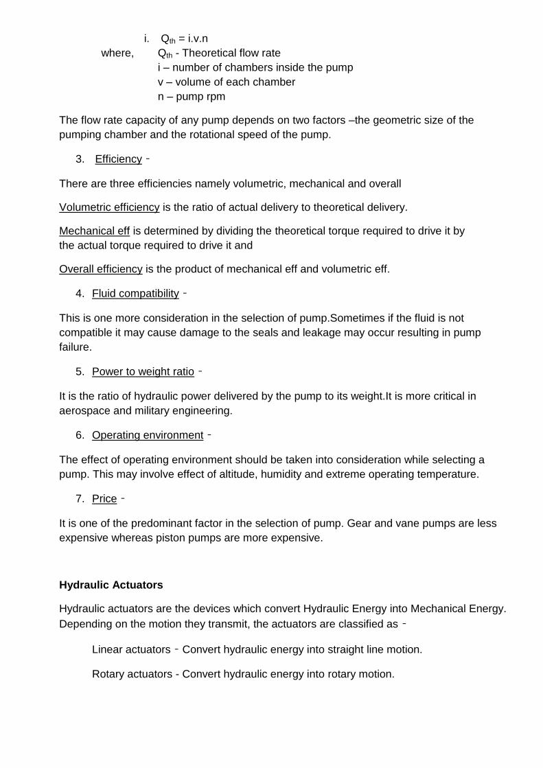
Single acting cylinder with single piston rod -
These are generally used for comparatively lower loads than plunger or ram type hydraulic
cylinders. This may be gravity return or spring return. This cylinder finds application in
production like clamping or pushing.
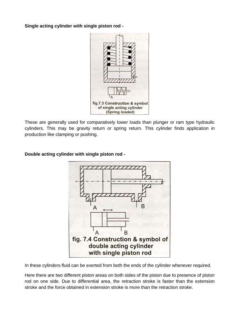
Double acting cylinder with single piston rod -
In these cylinders fluid can be exerted from both the ends of the cylinder whenever required.
Here there are two different piston areas on both sides of the piston due to presence of piston
rod on one side. Due to differential area, the retraction stroke is faster than the extension
stroke and the force obtained in extension stroke is more than the retraction stroke.

Double acting cylinder with double piston rod –
They have piston rods on both sides of the piston.
Since the annular area is same on both sides, the forward and reverse strokes have same
speed and force.
Tandem Cylinder –
A tandem cylinder is a combination of two or more cylinders working in tandem i.e. coupled
mechanically to each other.
Each cylinder has its own inlet and outlet ports, but can not operate independent of each
other. The piston rod of the first cylinder enters through the base of the second cylinder and
pushes its base. In this manner the greater effective surface area of both pistons generates
greater force, despite a small cylinder diameter and unaltered operating pressure.
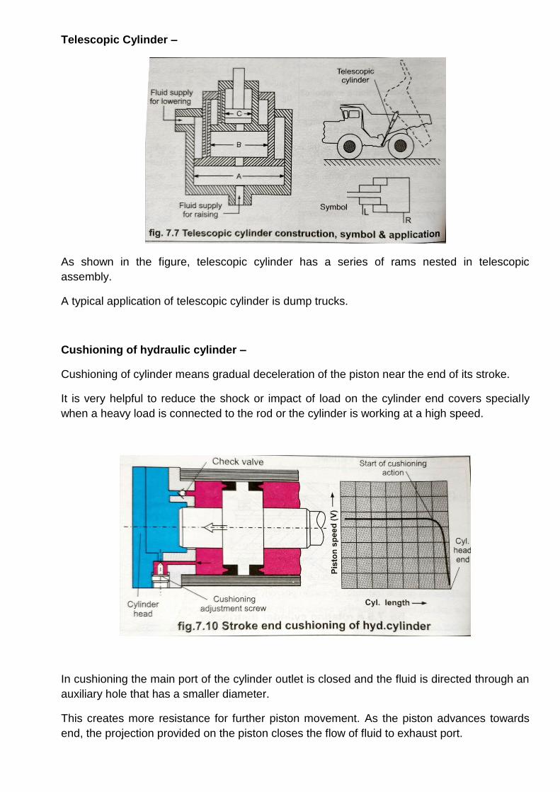
Telescopic Cylinder –
As shown in the figure, telescopic cylinder has a series of rams nested in telescopic
assembly.
A typical application of telescopic cylinder is dump trucks.
Cushioning of hydraulic cylinder –
Cushioning of cylinder means gradual deceleration of the piston near the end of its stroke.
It is very helpful to reduce the shock or impact of load on the cylinder end covers specially
when a heavy load is connected to the rod or the cylinder is working at a high speed.
In cushioning the main port of the cylinder outlet is closed and the fluid is directed through an
auxiliary hole that has a smaller diameter.
This creates more resistance for further piston movement. As the piston advances towards
end, the projection provided on the piston closes the flow of fluid to exhaust port.

Now the fluid takes the path through small passage provided on the bottom side of cylinder
head and slows down the piston speed.
The screw provided in the head varies the flow of fluid through passage and thus controls the
cushioning speed. The end of the cushion nose is tapered, chamfered or rounded in order to
allow it to enter more easily into the cushioning chamber.
When the cylinder is extending, in order to achieve fast start up a check valve is provided.
This valve provides additional flow of fluid in the cylinder.
Rotary Actuators –
A hydraulic motor transforms hydraulic energy into rotational mechanical energy. Hydraulic
motors resemble hydraulic pumps in construction and size.
The only difference is that instead of pushing the fluid as the pump does, in a hydraulic motor
the rotating elements i.e. vanes, gears, pistons are pushed by the oil pressure to enable the
motor shaft to rotate and thus helps in continuous or partial rotating motion.
Hydraulic motors are rated according to –
1. Displacement – It is the amount of fluid which the motor may accept in turning one
revolution.
2. Torque capacity – Torque is the force component of the output of the motor.
It may be mentioned that motion is not required for a torque, but motion will result if the torque
is sufficient to overcome friction and resistance of the load.
Hydraulic motors may be –
Uni-Directional or Bi-Directional
As per the construction they may be –
Gear type, Vane type, or Piston type
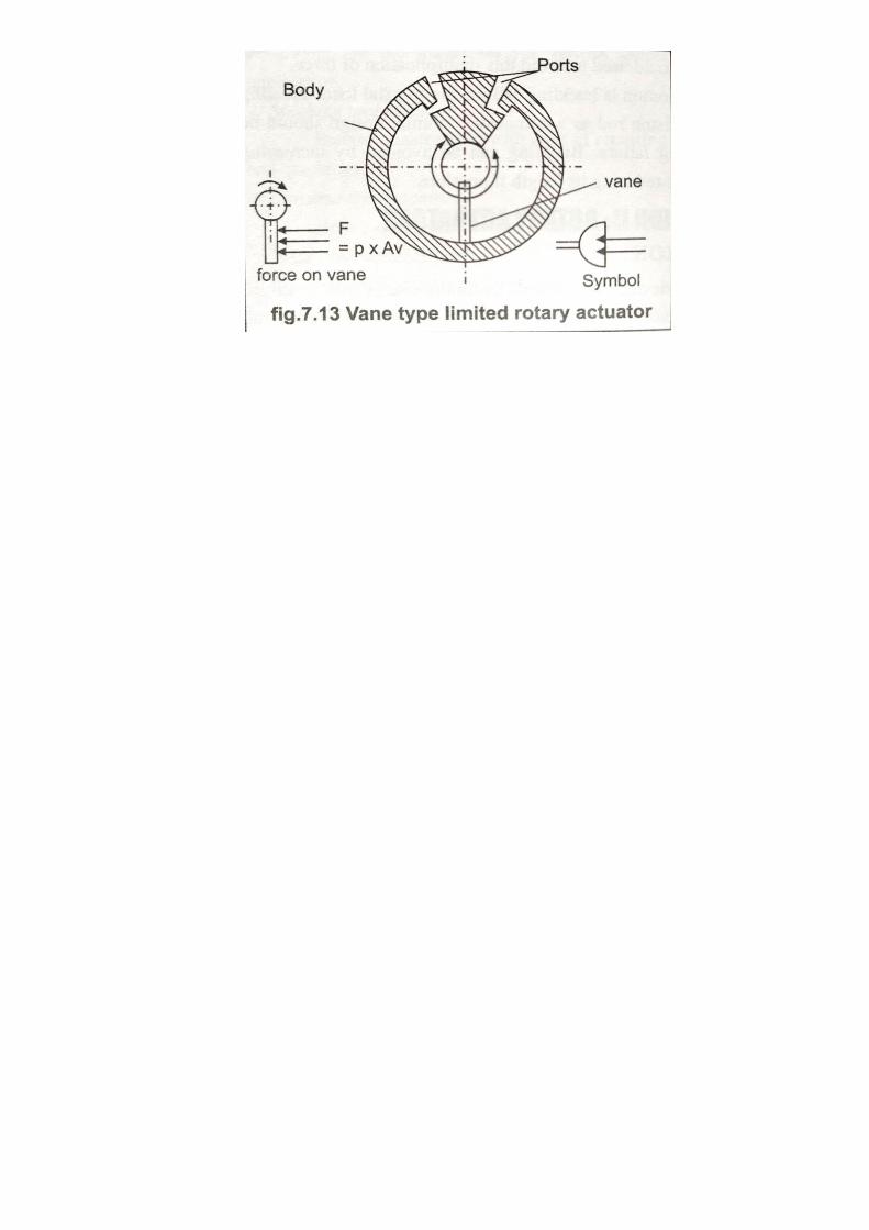
Vane type rotary actuator –
As shown in the figure, one or more vanes are attached to the shaft.The vanes are mounted
centrally and their rotation is limited by stops.
The pressure difference in the two chambers creates a differential pressure on the vane
causing the vane to rotate and thus rotate the shaft.