CHAPTER-2 NETWORK THEOREMS. CONTENT 1. Kirchhoff’s laws, voltage sources and current sources. 2....
129
CHAPTER-2 NETWORK THEOREMS
-
Upload
felix-woods -
Category
Documents
-
view
242 -
download
4
Transcript of CHAPTER-2 NETWORK THEOREMS. CONTENT 1. Kirchhoff’s laws, voltage sources and current sources. 2....

CHAPTER-2
NETWORK THEOREMS

CONTENT
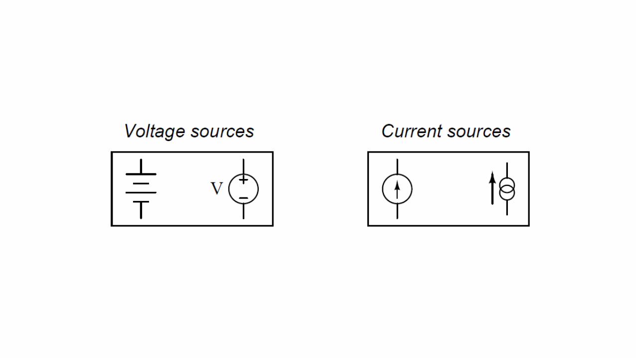
1. Kirchhoff’s laws, voltage sources and current sources.
2. Source conversion, simple problems in source conversion.
3. Superposition theorem, simple problems in super position theorem.
4. Thevenin’s theorem, Norton’s theorem, simple problems.
5.Reciprocity theorem, Maximum power transfer theorem, simple problems.
6. Delta/star and star/delta transformation.

Gustav Robert Kirchhoff

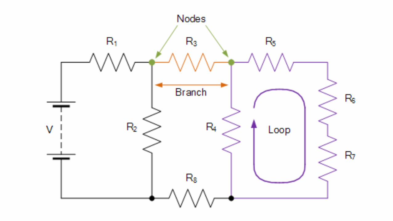
Definitions
• Circuit – It is an interconnection of electrical elements in a closed path by conductors(wires).
• Node – Any point where two or more circuit elements are connected together
• Branch –A circuit element between two nodes• Loop – A collection of branches that form a closed path returning to
the same node without going through any other nodes or branches twice
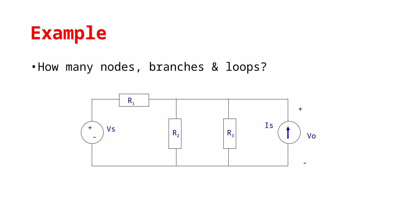
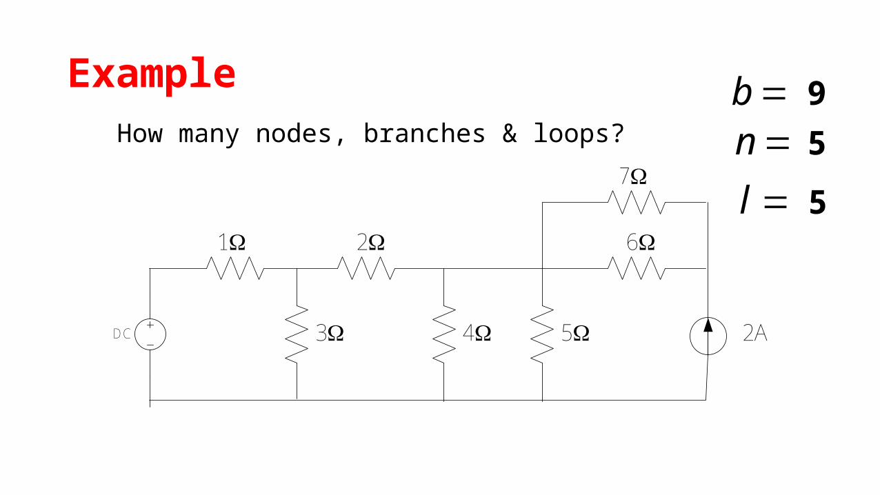
Example
• How many nodes, branches & loops?
+ -
Vs Is
R1
R2 R3
+
Vo
-
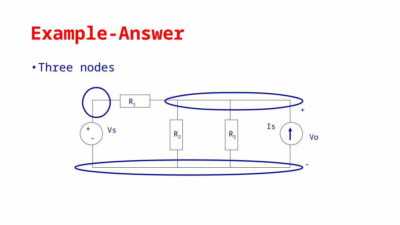
Example-Answer
• Three nodes
+ -
Vs Is
R1
R2 R3
+
Vo
-
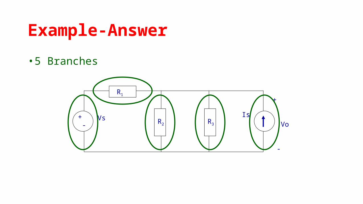
Example-Answer
• 5 Branches
+ -
Vs Is
R1
R2 R3
+
Vo
-

Example-Answer
• Three Loops, if starting at node A
+ -
Vs Is
R1
R2 R3
+
Vo
-
A B
C
Example
DC
1 2
3 4 5
6
7
2A
How many nodes, branches & loops?bn
l
9
5
5

Kirchhoff's Current Law (KCL)
Also called Kirchhoff's Point law and Kirchhoff's First rule..

Kirchhoff's Current Law (KCL)
Total volume of water flowing through pipe 1 = (total volume of water flowing through pipe 2 + total volume of water flowing through pipe 3)
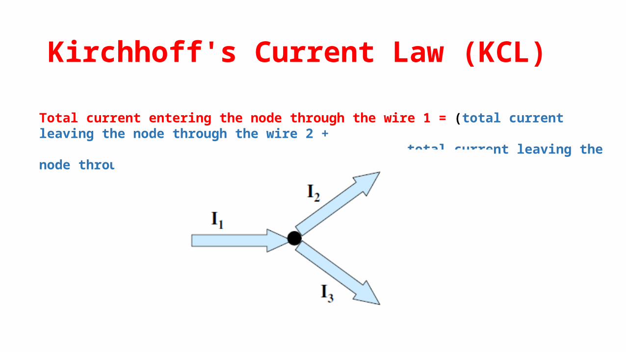
Kirchhoff's Current Law (KCL)
Total current entering the node through the wire 1 = (total current leaving the node through the wire 2 + total current leaving the node through the wire 3)
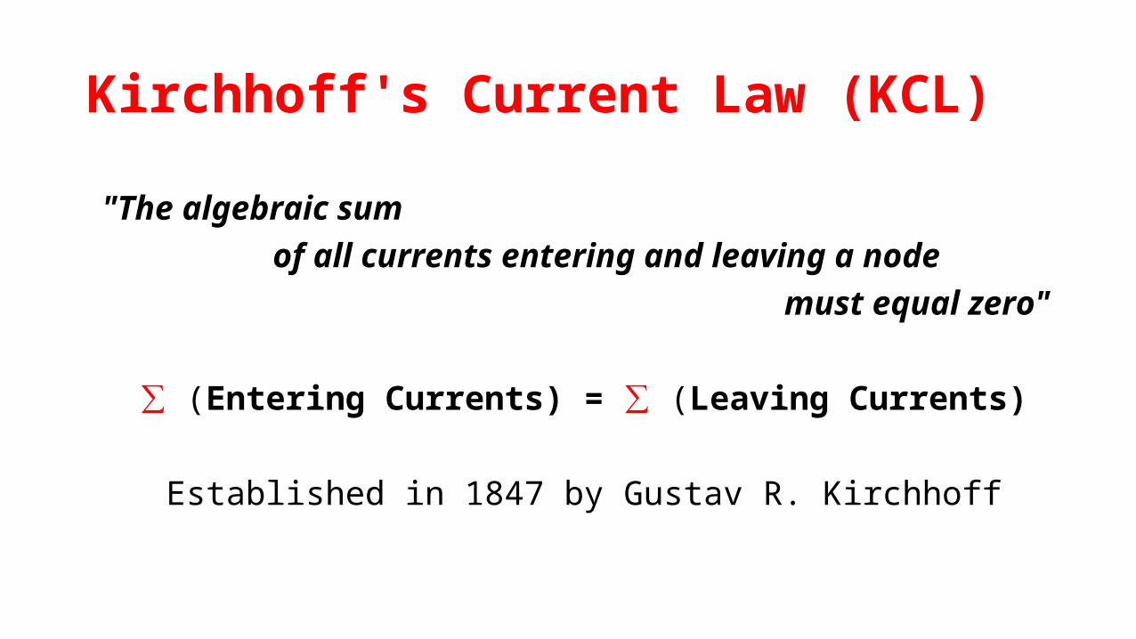
Kirchhoff's Current Law (KCL)
"The algebraic sum of all currents entering and leaving a node
must equal zero"
∑ (Entering Currents) = ∑ (Leaving Currents)
Established in 1847 by Gustav R. Kirchhoff

Kirchhoff's Current Law (KCL)
It states that, in any linear network the algebraic sum of the
current meeting at a point (junction) is zero.
∑ I (Junction) = 0
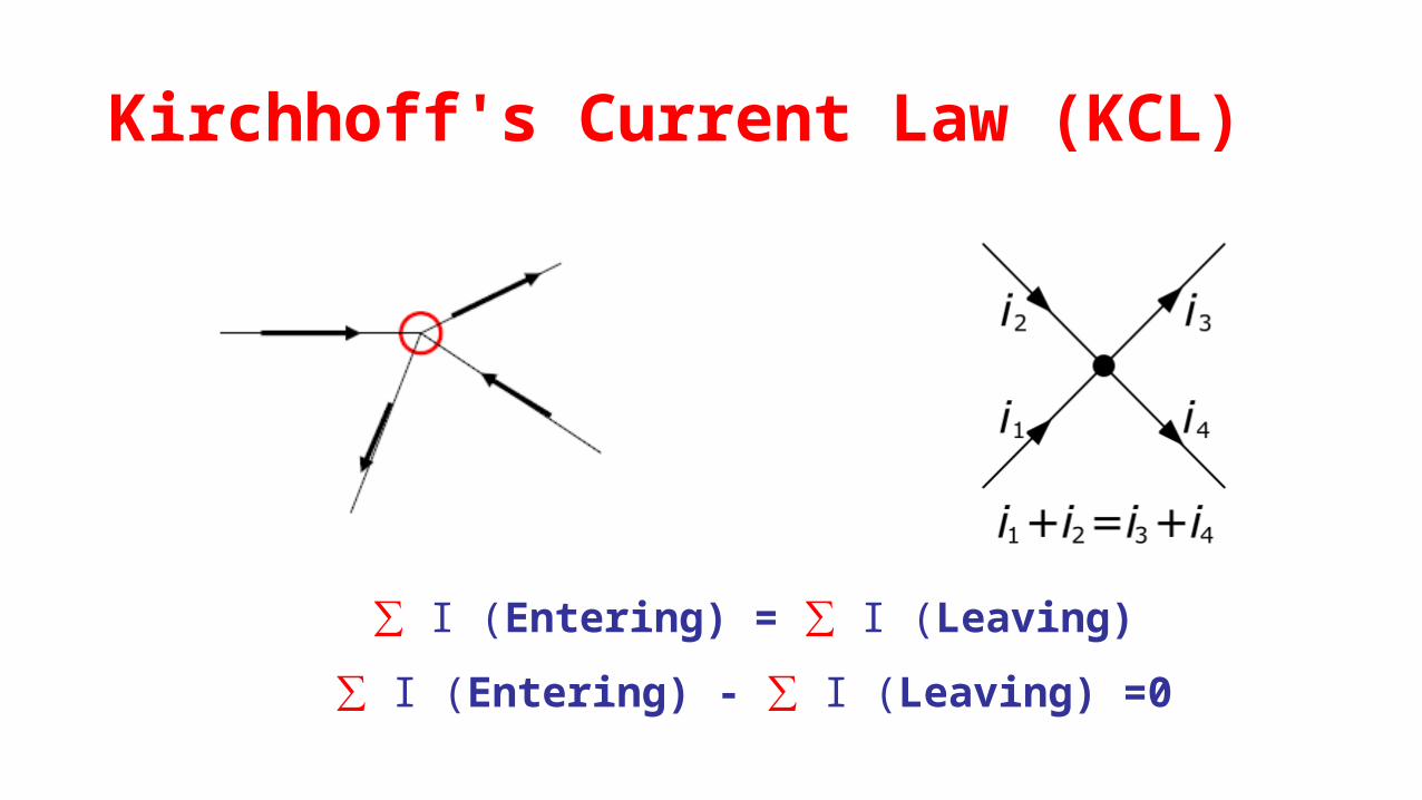
∑ I (Entering) = ∑ I (Leaving)
∑ I (Entering) - ∑ I (Leaving) =0
Kirchhoff's Current Law (KCL)

Assign positive signs to the currents entering the node and
negative signs to the currents leaving the node, the KCL can be re-
formulated as:
All currents at the node) =
Kirchhoff's Current Law (KCL)

Kirchhoff's Current Law (KCL)

Kirchhoff's Current Law (KCL)

Kirchhoff's Current Law (KCL)

Example
I1= 1 A
I2= 3 A
I3= 0.5 A
Find the current I4 in A
Kirchhoff's Voltage Law (KVL)
Also called Kirchhoff's loop rule and Kirchhoff's second rule..
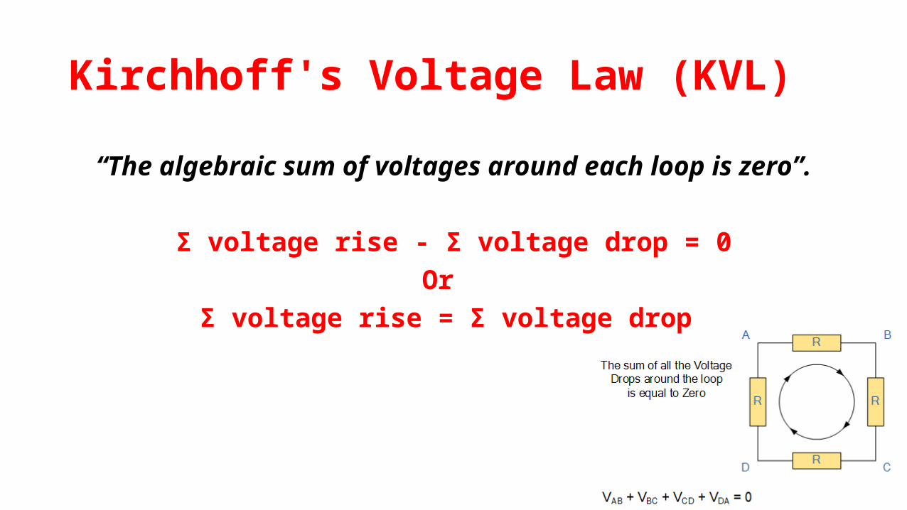
Kirchhoff's Voltage Law (KVL)
“The algebraic sum of voltages around each loop is zero”.
Σ voltage rise - Σ voltage drop = 0Or
Σ voltage rise = Σ voltage drop

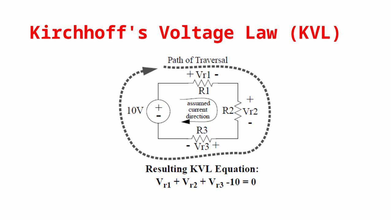
Kirchhoff's Voltage Law (KVL)
It states that, in any linear bilateral active closed network the
algebraic sum of the product of the current and resistance in each of
the conductors in any closed path (mesh) in the network plus the
algebraic sum of e.m.f in the path is zero.
∑ IR + ∑ e.m.f = 0
Kirchhoff's Voltage Law (KVL)

The sign of each voltage is the polarity of the terminal first encountered
in traveling around the loop.The direction of travel is arbitrary.
Clockwise:
Counter-clockwise:
0 1 2 0V V V
2 1 0 0V V V
0 1 2V V V V0
I
R1
R2
V1
V2
A +
+
-
-
Sign Convention
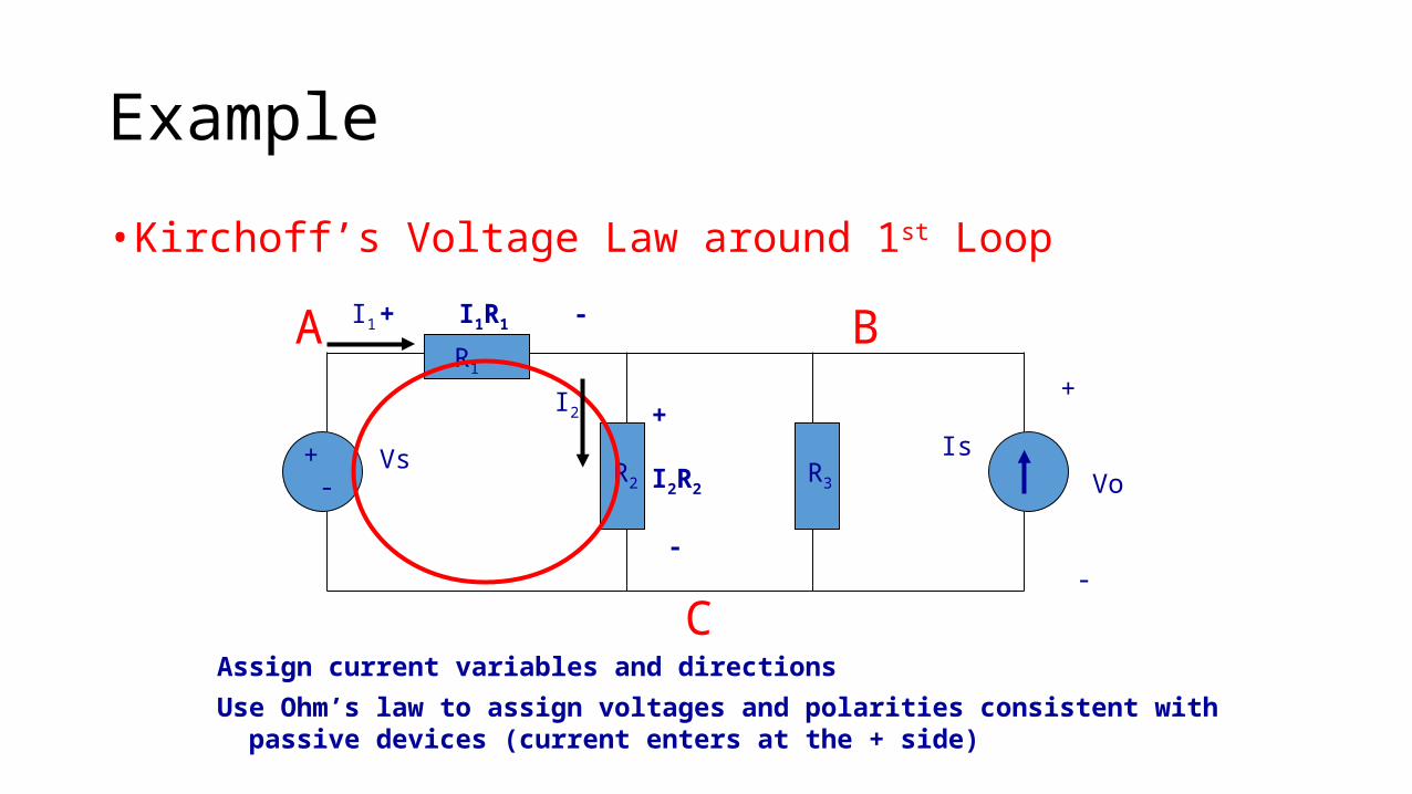
Example
• Kirchoff’s Voltage Law around 1st Loop
+ -
Vs Is
R1
R2 R3
+
Vo
-
A B
C
I2
I1
+
I2R2
-
+ I1R1 -
Assign current variables and directions
Use Ohm’s law to assign voltages and polarities consistent with passive devices (current enters at the + side)

Example
• Kirchoff’s Voltage Law around 1st Loop
+ -
Vs Is
R1
R2 R3
+
Vo
-
A B
C
I2
I1
+
I2R2
-
+ I1R1 -
Starting at node A, add the 1st voltage drop: + I1R1

Example
• Kirchoff’s Voltage Law around 1st Loop
+ -
Vs Is
R1
R2 R3
+
Vo
-
A B
C
I2
I1
+
I2R2
-
+ I1R1 -
Add the voltage drop from B to C through R2: + I1R1 + I2R2

Example
• Kirchoff’s Voltage Law around 1st Loop
+ -
Vs Is
R1
R2 R3
+
Vo
-
A B
C
I2
I1
+
I2R2
-
+ I1R1 -
Subtract the voltage rise from C to A through Vs: + I1R1 + I2R2 – Vs = 0
Notice that the sign of each term matches the polarity encountered 1st

Source Conversion
DCsv
sRabv
+
-
abv
+
-
sRs
s
v
R
ai 'ai

Voltage Source to Current Source

Current Source to Voltage Source
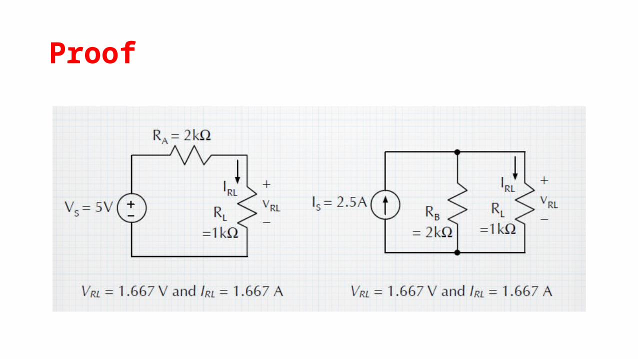
Proof
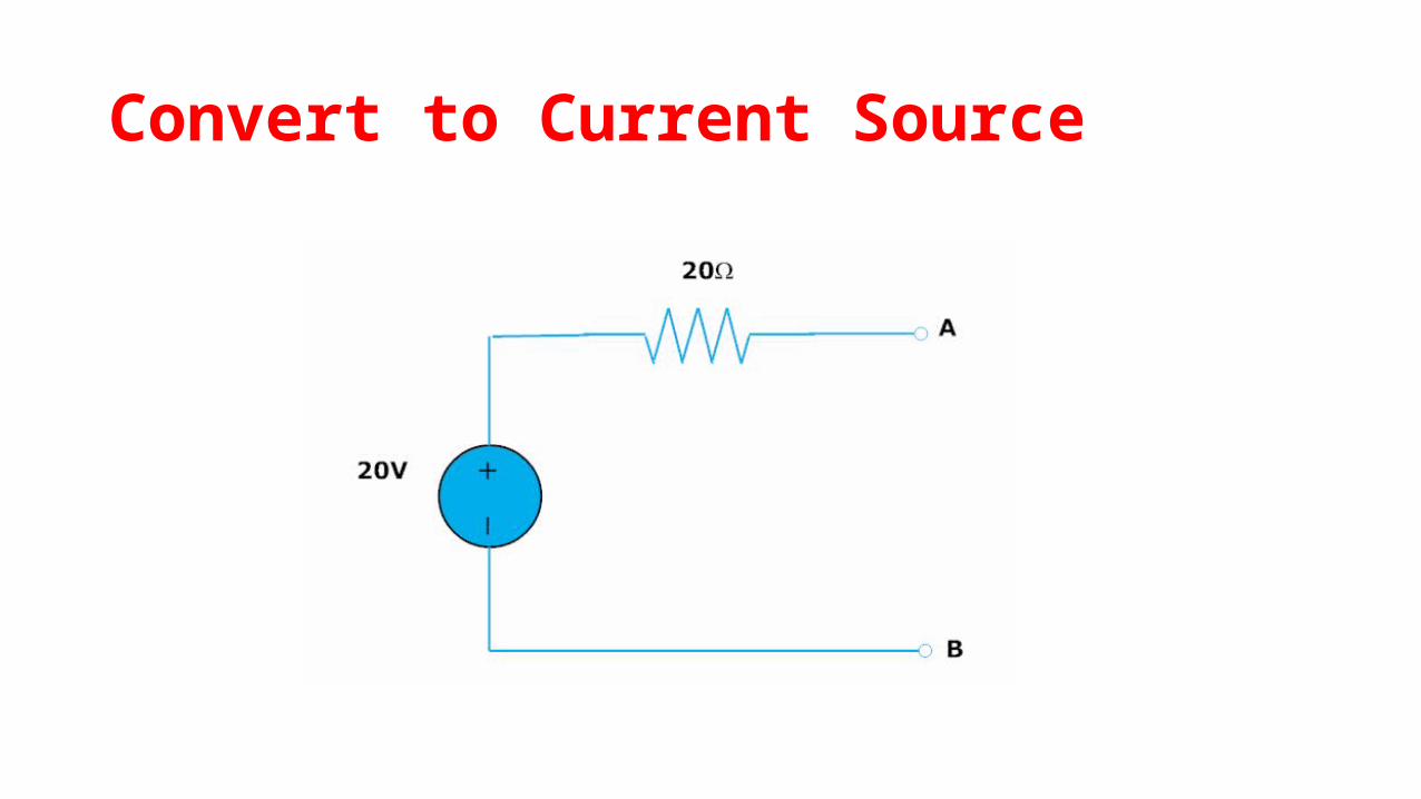
Convert to Current Source

Answer-1

Convert to Voltage Source
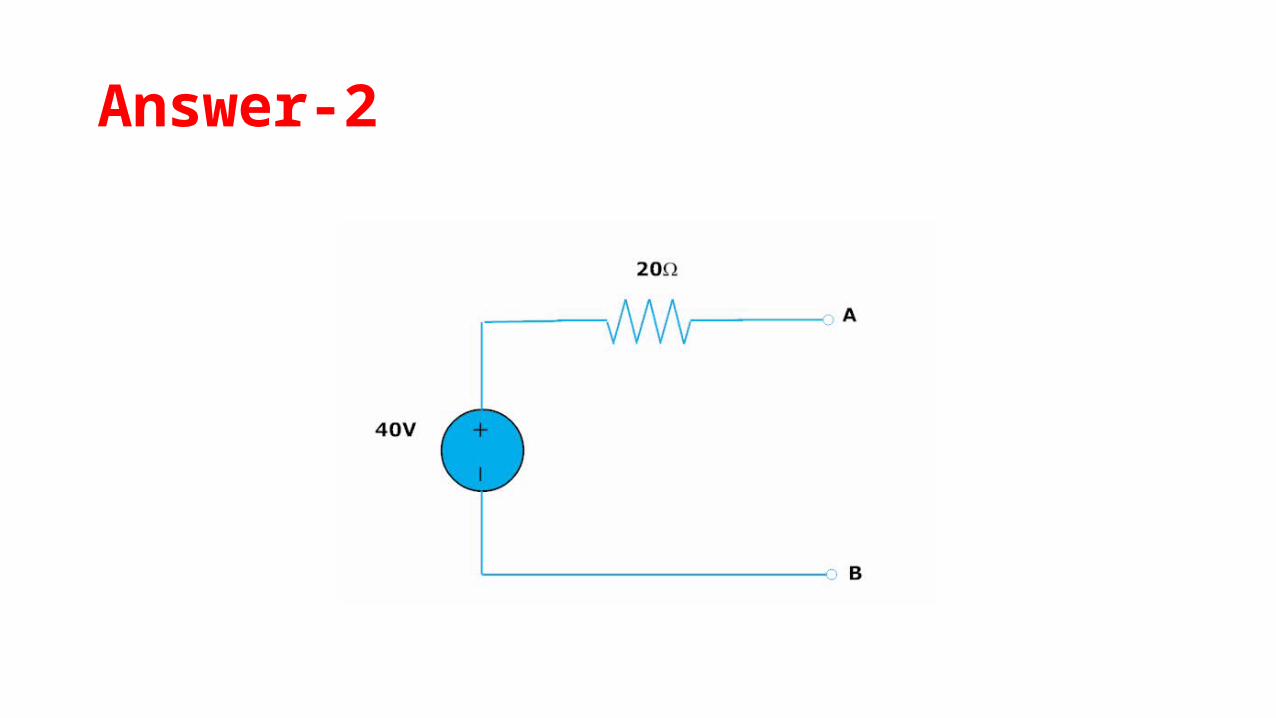
Answer-2

Superposition Theorem
STATEMENT-
In a network of linear resistances containing more than one
generator (or source of e.m.f.), the current which flows at any point is
the sum of all the currents which would flow at that point if each
generator were considered separately and all the other generators
replaced for the time being by resistances equal to their internal
resistances.

Superposition Theorem
STATEMENT-
In a linear circuit with several sources the voltage and
current responses in any branch is the algebraic sum of the voltage
and current responses due to each source acting independently with
all other sources replaced by their internal impedance.
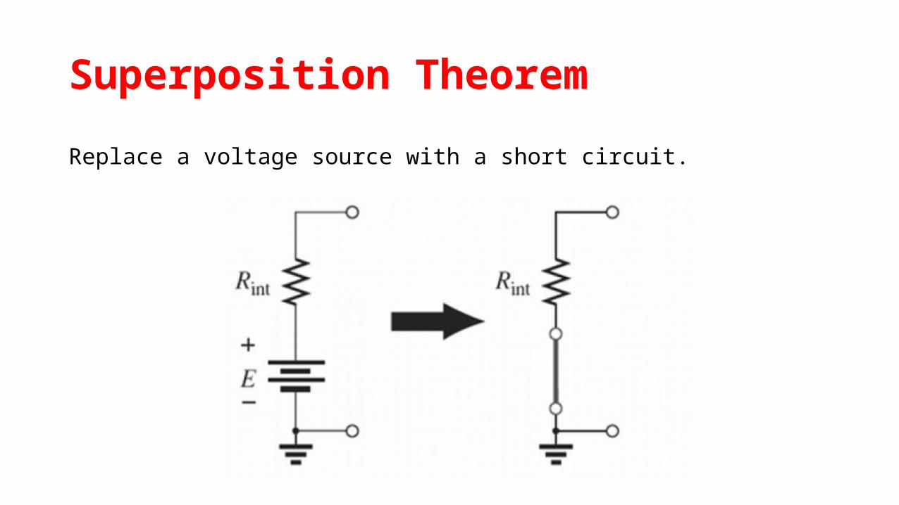
Superposition Theorem
Replace a voltage source with a short circuit.

Superposition Theorem
Replace a current source with an open circuit.
Superposition Theorem
Step-1:
Select a single source acting alone. Short the other voltage
source and open the current sources, if internal impedances are not
known. If known, replace them by their internal resistances.
Superposition Theorem
Step-2:
Find the current through or the voltage across the required
element, due to the source under consideration, using a suitable
network simplification technique.
Superposition Theorem
Step-3:
Repeat the above two steps far all sources.
Superposition Theorem
Step-4:
Add all the individual effects produced by individual sources, to
obtain the total current in or voltage across the element.

Explanation
Superposition Theorem
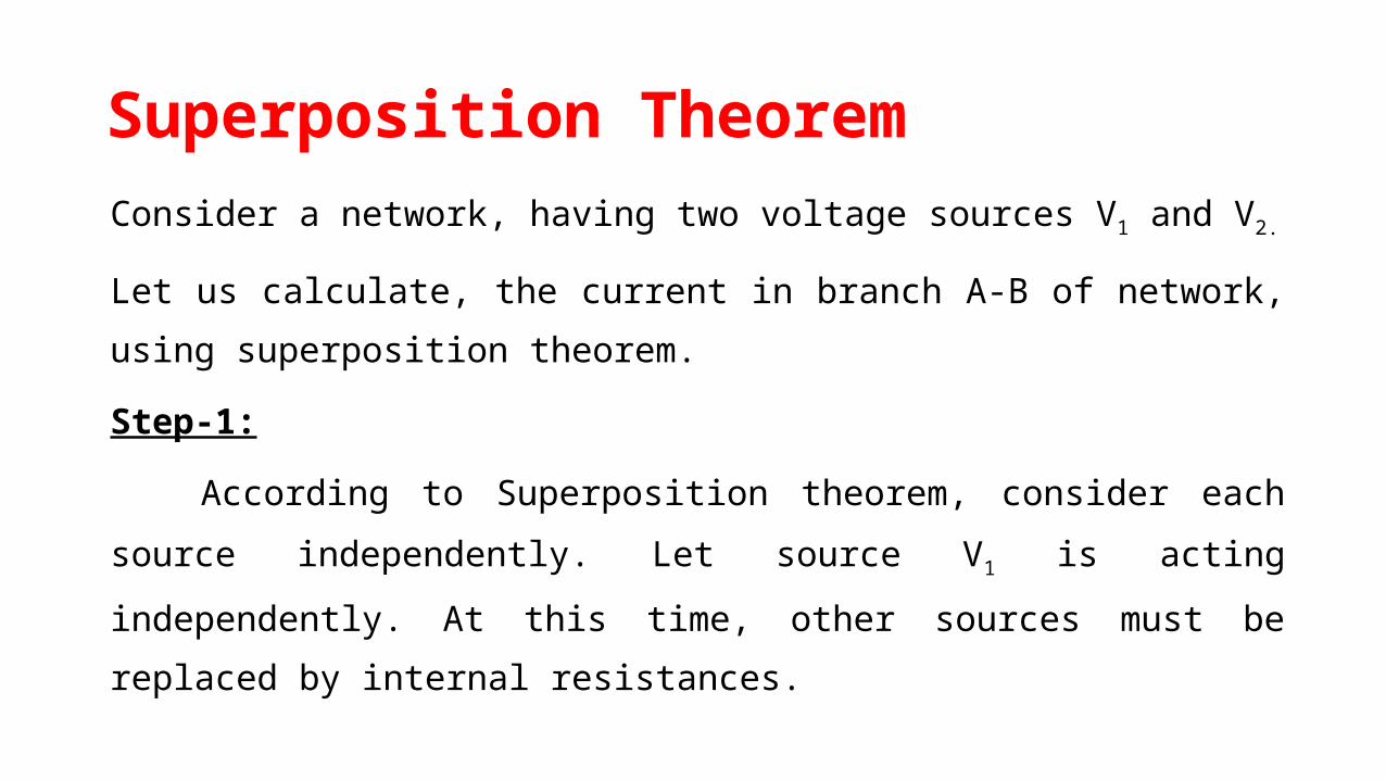
Consider a network, having two voltage sources V1 and V2.
Let us calculate, the current in branch A-B of network, using
superposition theorem.
Step-1:
According to Superposition theorem, consider each source
independently. Let source V1 is acting independently. At this time,
other sources must be replaced by internal resistances.
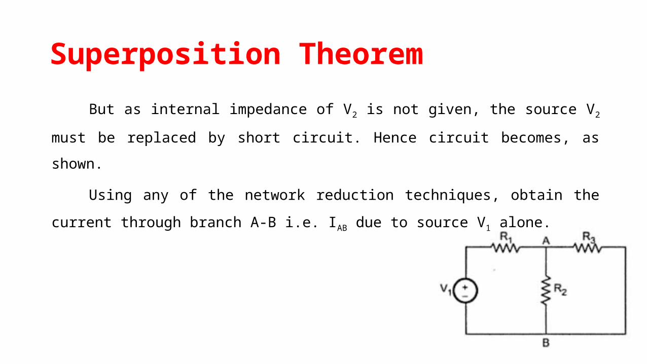
Superposition Theorem
But as internal impedance of V2 is not given, the source V2 must
be replaced by short circuit. Hence circuit becomes, as shown.
Using any of the network reduction techniques, obtain the
current through branch A-B i.e. IAB due to source V1 alone.
Superposition Theorem
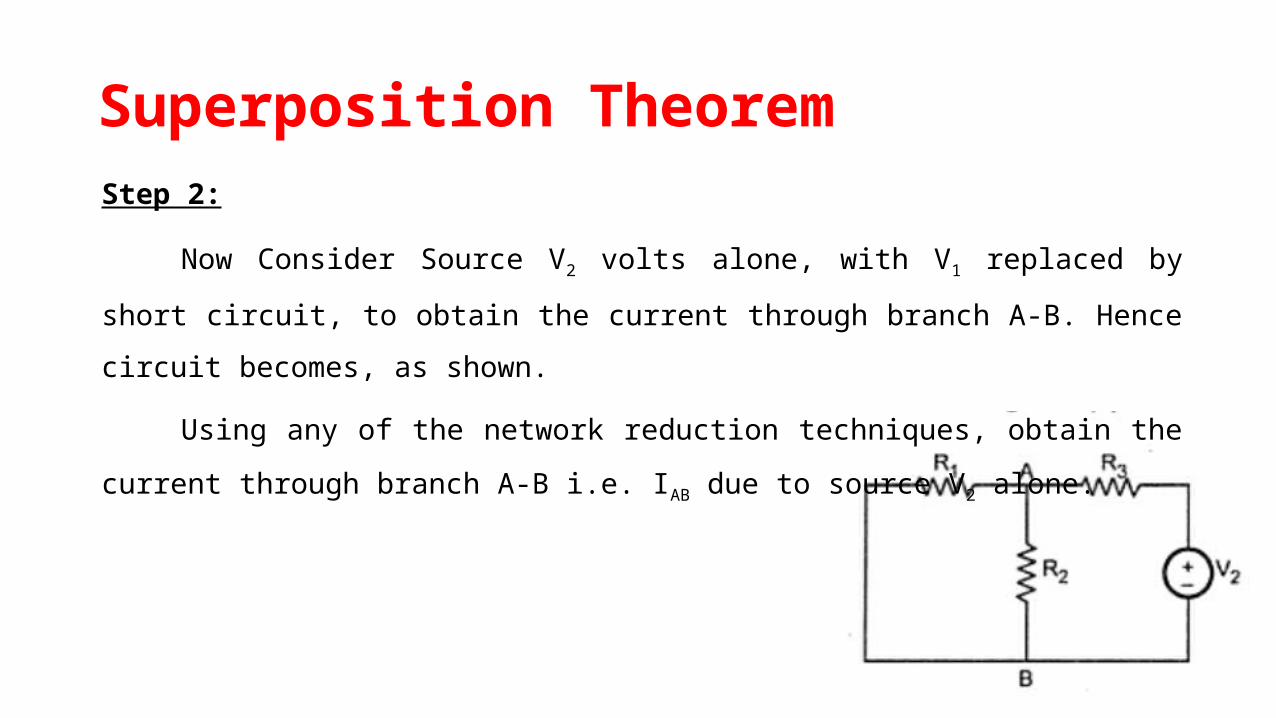
Step 2:
Now Consider Source V2 volts alone, with V1 replaced by short circuit,
to obtain the current through branch A-B. Hence circuit becomes, as shown.
Using any of the network reduction techniques, obtain the current
through branch A-B i.e. IAB due to source V2 alone.
Superposition Theorem
Step 3:
According to the Superposition theorem, the total current
through branch A-B is sum of the currents through branch A-B
produced by each source acting independently.
Total IAB = IAB due to V1 + IAB due to V2
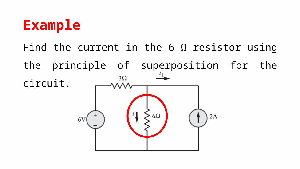
Example
Find the current in the 6 Ω resistor using the principle of
superposition for the circuit.
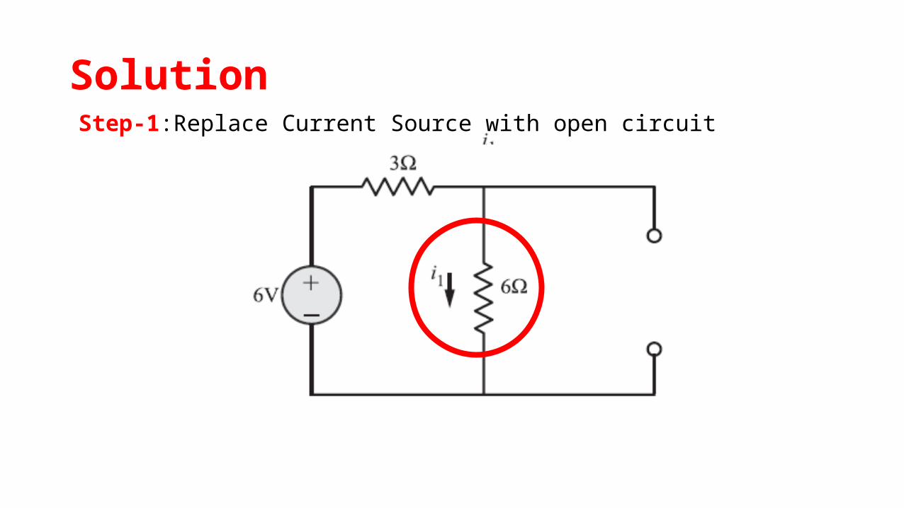
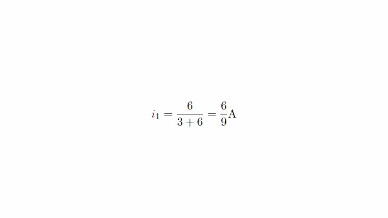
SolutionStep-1:Replace Current Source with open circuit

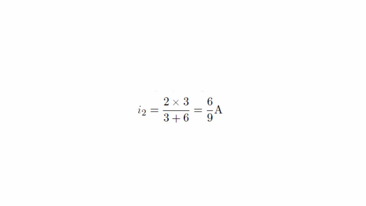
Step-2:Replace Voltage Source with Short circuit
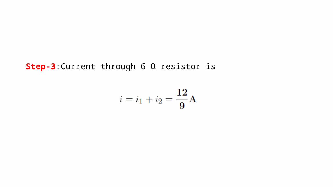
Step-3:Current through 6 Ω resistor is

Thevenin’s theorem

Thevenin’s theorem
Statement
“Any linear circuit containing several voltages and
resistances can be replaced by just a Single Voltage VTH in series with a
Single Resistor RTH “.

Thevenin’s theorem
VTH
Req or RTH
Thevenin’s Equivalent Circuit

Thevenin’s theorem

Steps to be followed for Thevenin’s TheoremStep 1:
Remove the branch resistance through which current is to be
calculated.
Step 2:
Calculate the voltage across these open circuited terminals, by
using any of the network simplification techniques. This is VTH.
Steps to be followed for Thevenin’s TheoremStep 3:
Calculate Req as viewed through the two terminals of the branch
from which current is to be calculated by removing that branch
resistance and replacing all independent sources by their internal
resistances. If the internal resistance are not known, then replace
independent voltage sources by short circuits and independent current
sources by open circuits.

Steps to be followed for Thevenin’s Theorem
Step 4:
Draw the Thevenin’s equivalent showing source VTH, with the resistance
Req in series with it, across the terminals of branch of interest.
Step 5:
Reconnect the branch resistance. Let it be RL. The required current
through the branch is given by,
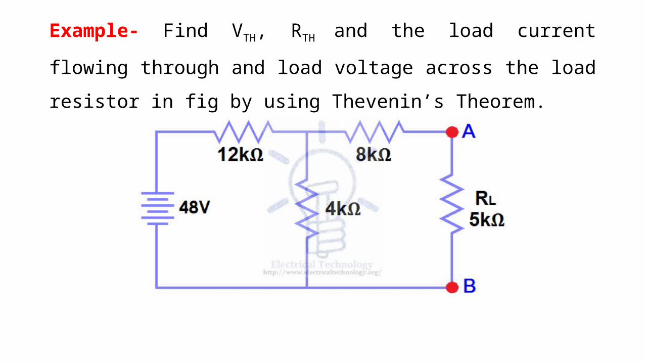
Example- Find VTH, RTH and the load current flowing through and
load voltage across the load resistor in fig by using Thevenin’s
Theorem.

Step 1- Open the 5kΩ load resistor
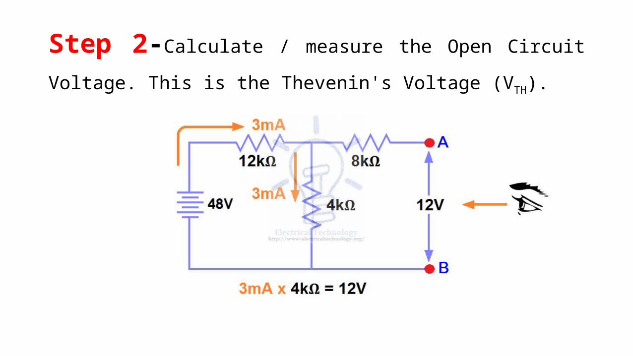
Step 2-Calculate / measure the Open Circuit Voltage. This is the
Thevenin's Voltage (VTH).

Step 3-Open Current Sources and Short Voltage Sources

Step 4-Calculate /measure the Open Circuit Resistance. This is
the Thevenin's Resistance (RTH)

Step 5-Connect the RTH in series with Voltage Source VTH and re-
connect the load resistor. i.e. Thevenin's circuit with load resistor. This
the Thevenin’s equivalent circuit.
Thevenin’s Equivalent Circuit=VTH
RTH =

Step 6- Calculate the total load current & load voltage

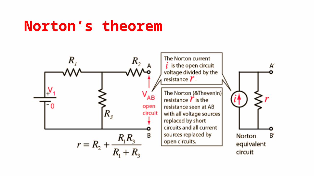
Norton’s theorem
Norton’s theorem
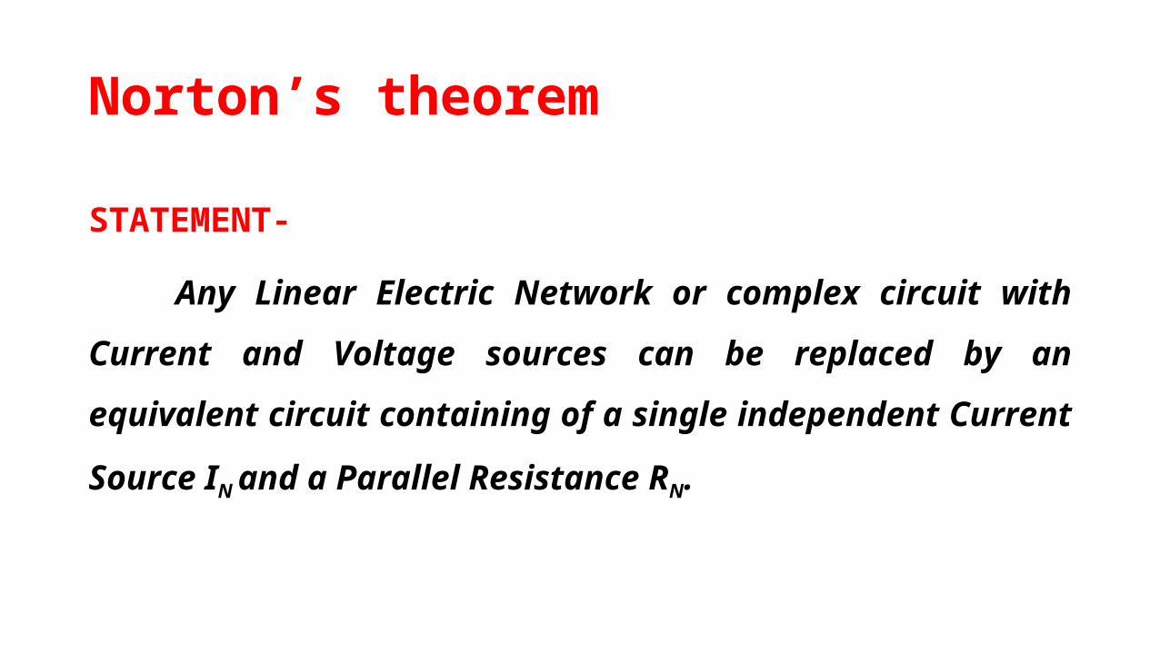
STATEMENT-
Any Linear Electric Network or complex circuit with Current and
Voltage sources can be replaced by an equivalent circuit containing of
a single independent Current Source IN and a Parallel Resistance RN.

Norton’s theorem
IINN
RRNN
Norton’s Equivalent Circuit
Norton’s theorem

Steps to be followed for Norton’s Theorem
Step 1:
Short the load resistor
Step 2:
Calculate / measure the Short Circuit Current.
This is the Norton Current (IN)
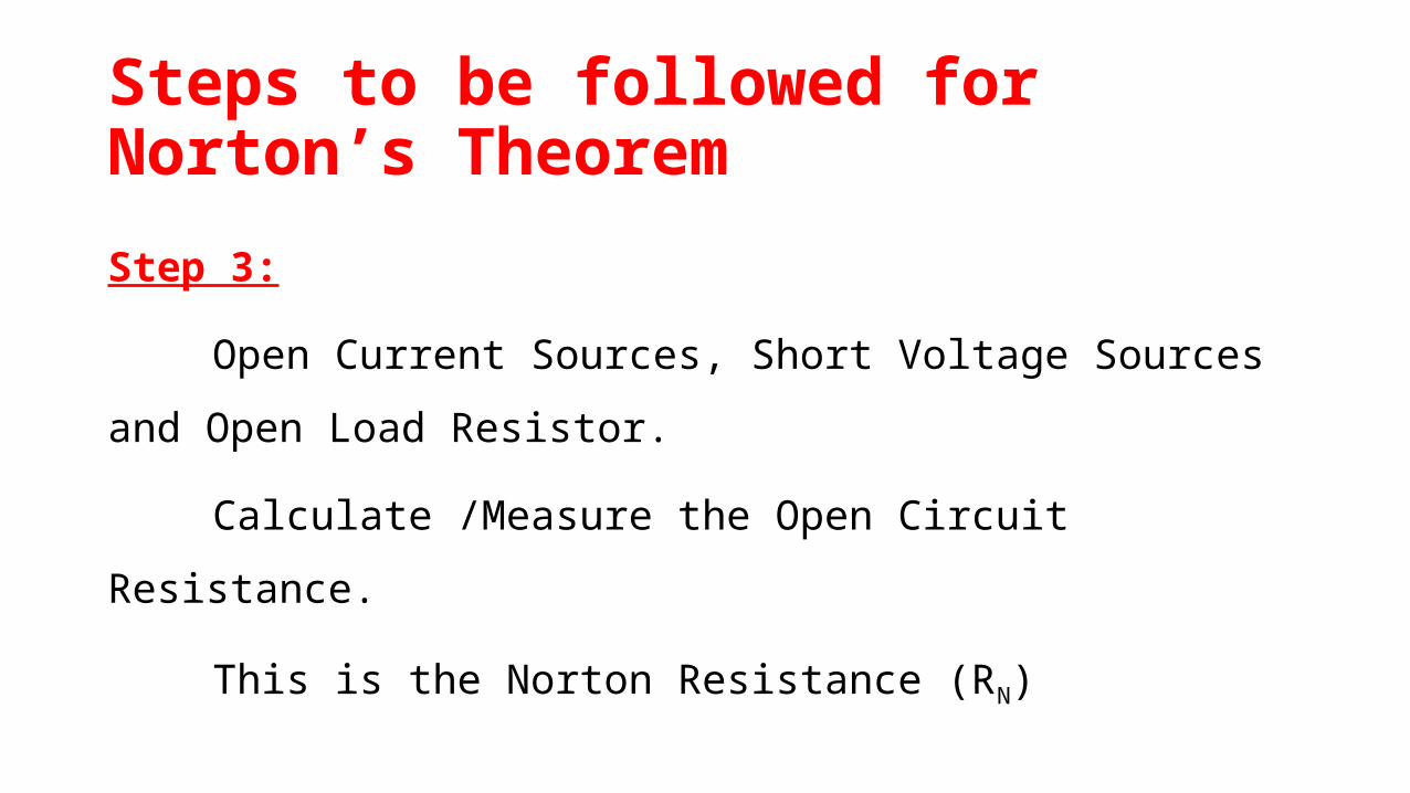
Steps to be followed for Norton’s Theorem
Step 3:
Open Current Sources, Short Voltage Sources and Open Load
Resistor.
Calculate /Measure the Open Circuit Resistance.
This is the Norton Resistance (RN)
Steps to be followed for Norton’s Theorem
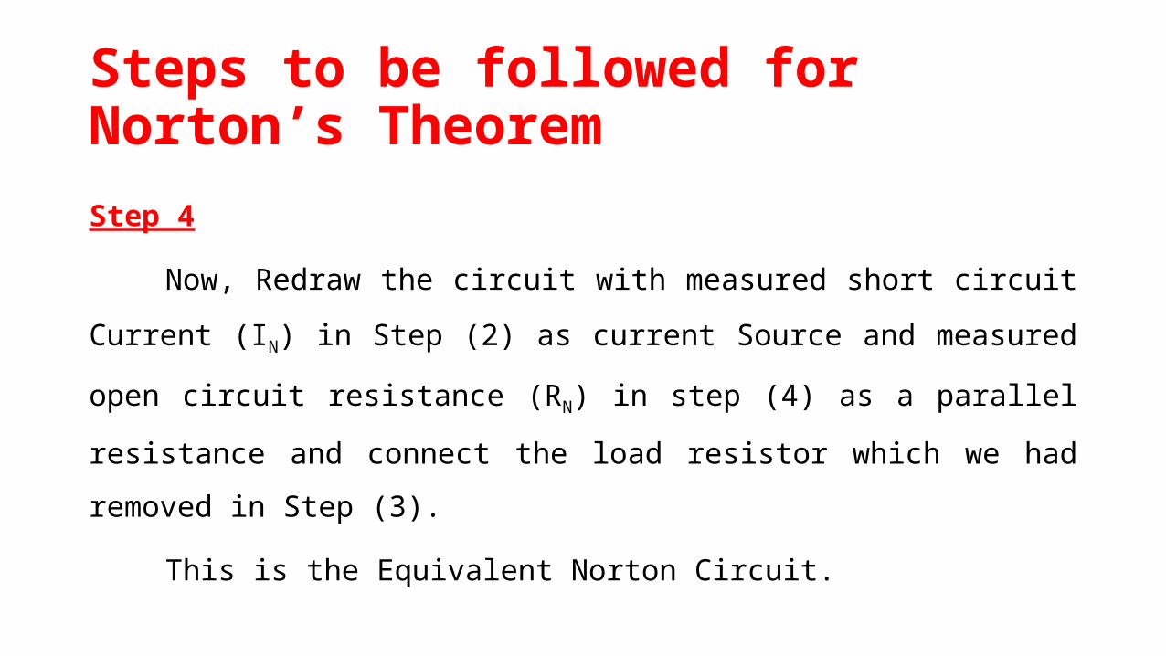
Step 4
Now, Redraw the circuit with measured short circuit Current (IN)
in Step (2) as current Source and measured open circuit resistance (RN)
in step (4) as a parallel resistance and connect the load resistor which
we had removed in Step (3).
This is the Equivalent Norton Circuit.

Steps to be followed for Norton’s Theorem

Example 1-Find RN, IN, the current flowing
through and Load Voltage across the load resistor
in fig (1) by using Norton’s Theorem.
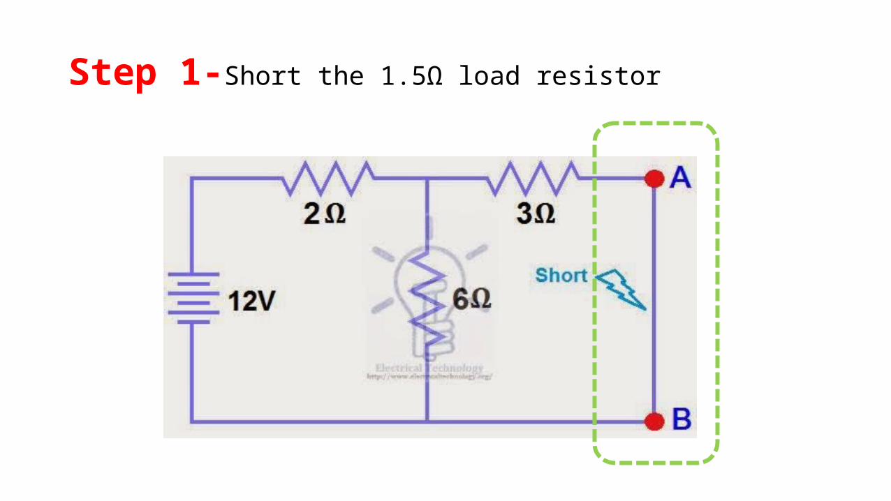
Step 1-Short the 1.5Ω load resistor
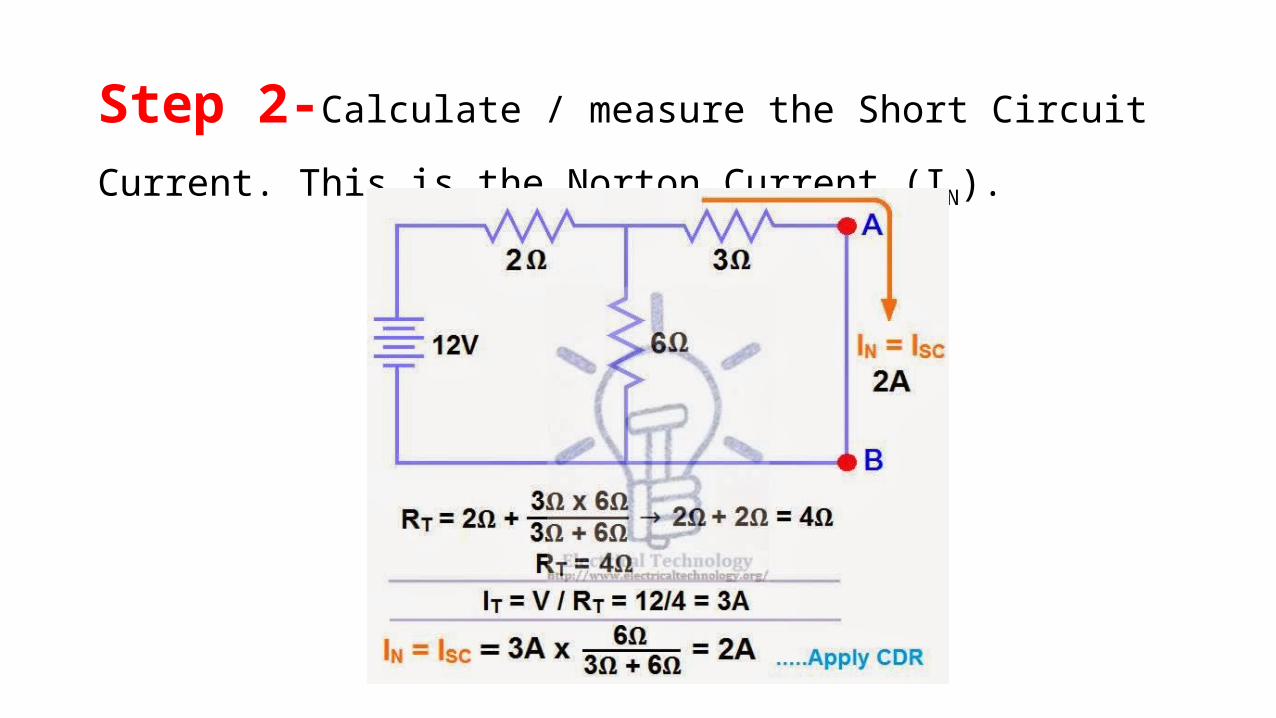
Step 2-Calculate / measure the Short Circuit Current. This is the
Norton Current (IN).

Step 3-Open Current Sources, Short Voltage Sources and Open
Load Resistor.
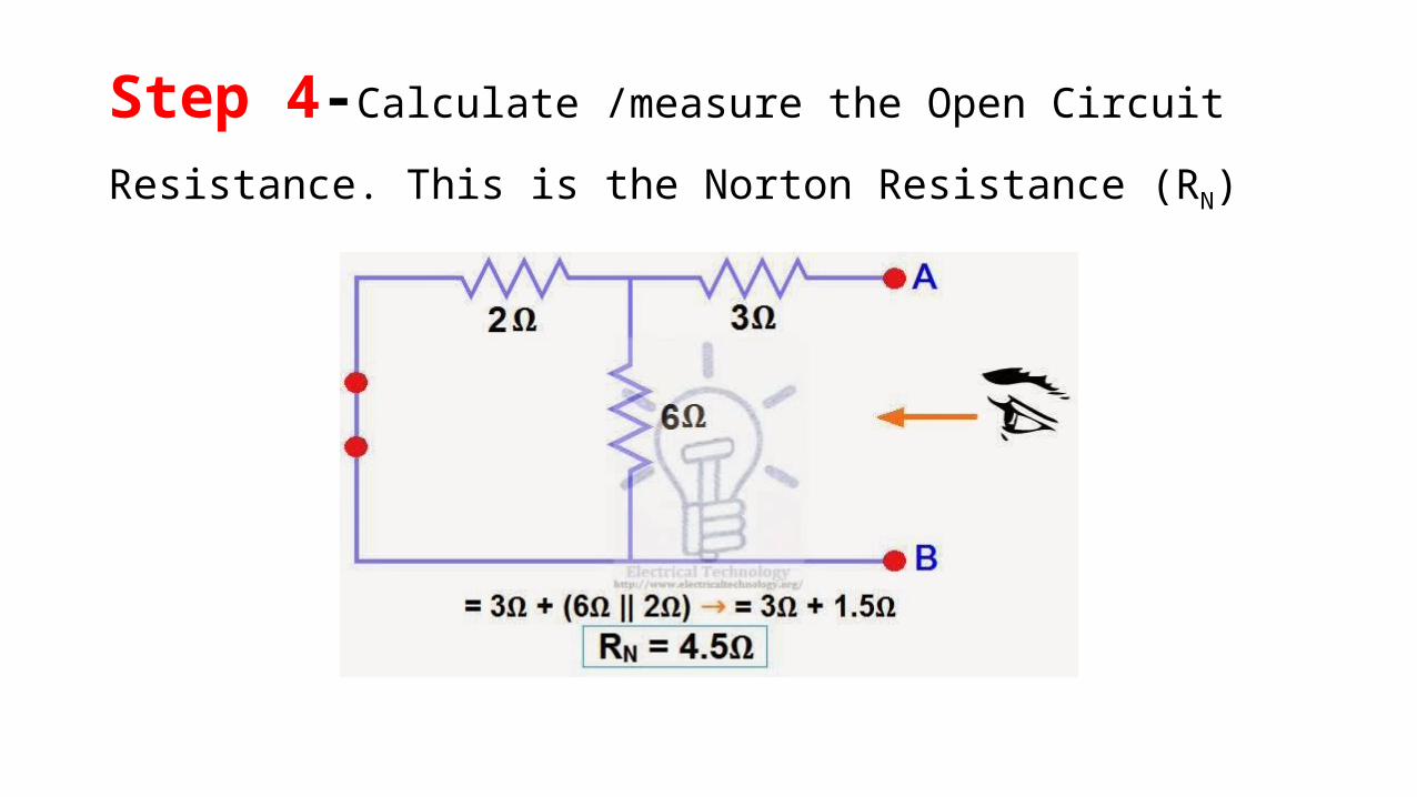
Step 4-Calculate /measure the Open Circuit Resistance. This is
the Norton Resistance (RN)

Step 5- Connect the RN in Parallel with Current Source INand
re-connect the load resistor.
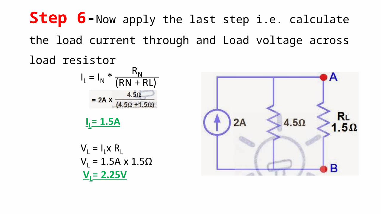
Step 6-Now apply the last step i.e. calculate the load current
through and Load voltage across load resistor

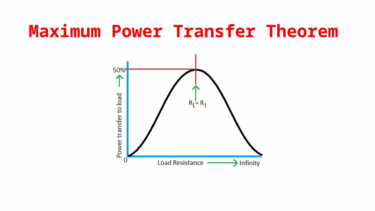
Maximum Power Transfer Theorem
Maximum Power Transfer Theorem
Statement:
In an active resistive network, maximum power transfer to the
load resistance takes place when the load resistance equals the
equivalent resistance of the network as viewed from the terminals of
the load.

Steps to be followed for MPTT
Maximum Power Transfer Theorem
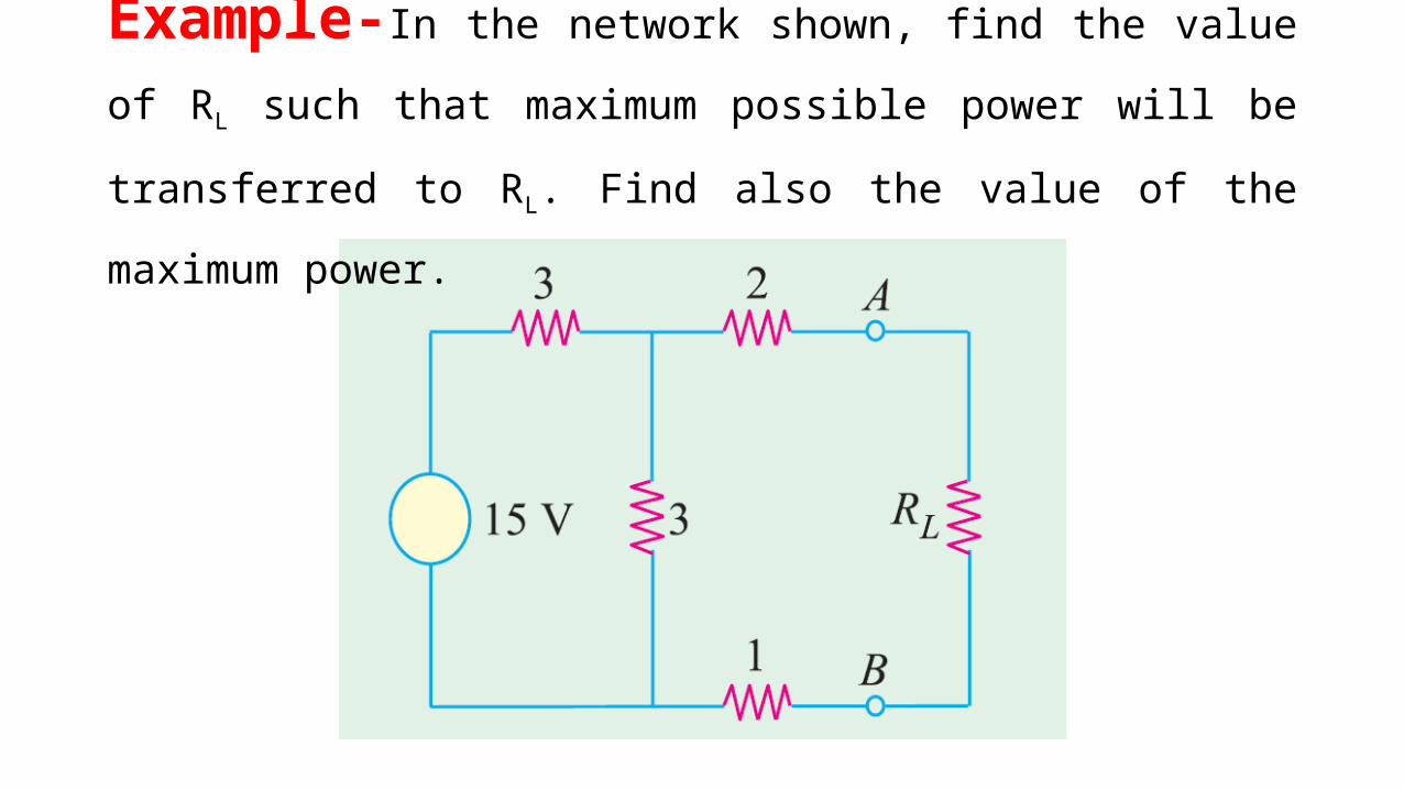
Example-In the network shown, find the value of RL such that
maximum possible power will be transferred to RL. Find also the value
of the maximum power.
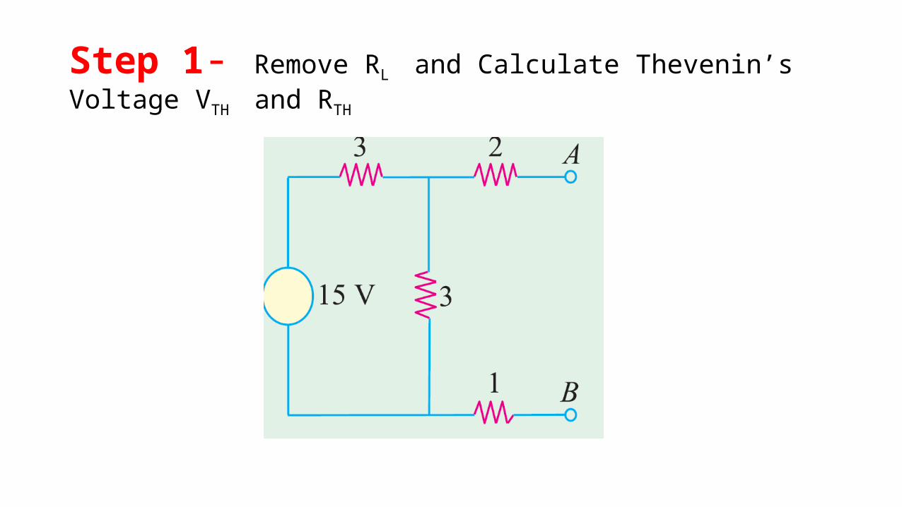
Step 1- Remove RL and Calculate Thevenin’s Voltage VTH and RTH
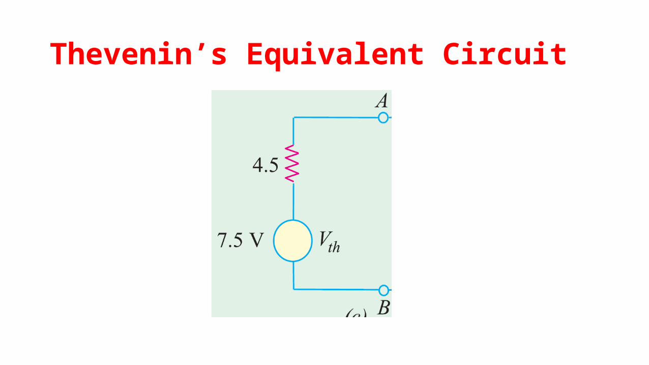
Thevenin’s Equivalent Circuit

Reciprocity Theorem
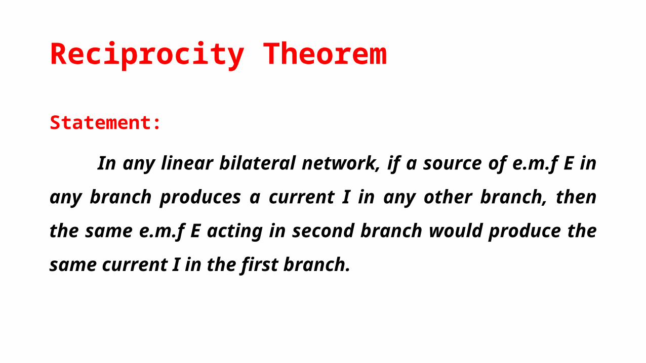
Statement:
In any linear bilateral network, if a source of e.m.f E in any
branch produces a current I in any other branch, then the same e.m.f
E acting in second branch would produce the same current I in the
first branch.

Reciprocity Theorem

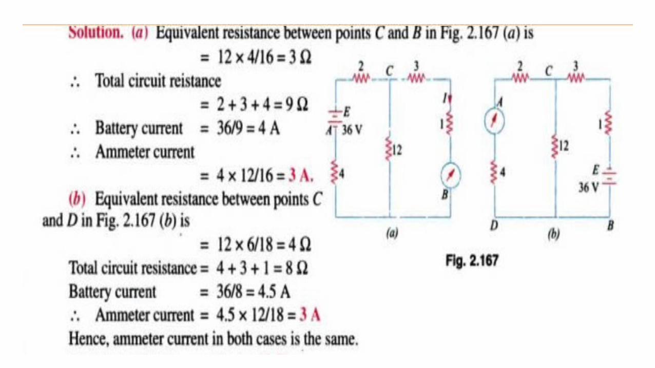
Example-In the network given below, find (a) ammeter
current when battery is at A and ammeter at B and (b) when battery is
at B and ammeter at point A.
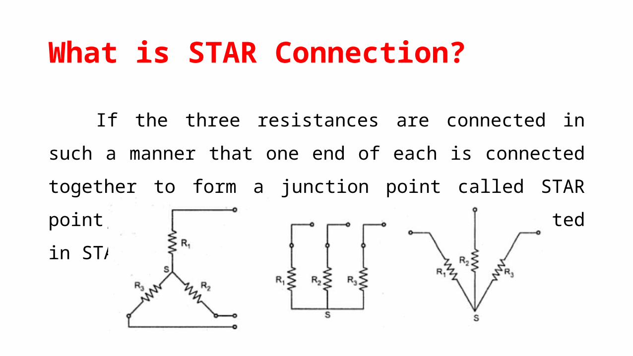
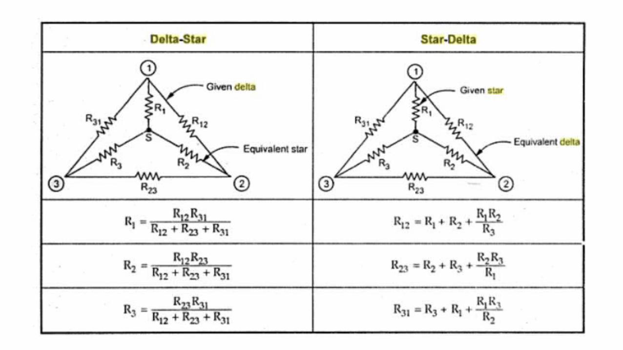
What is STAR Connection?
If the three resistances are connected in such a manner that one
end of each is connected together to form a junction point called STAR
point, the resistances are said to be connected in STAR.

Star or Y or T Network
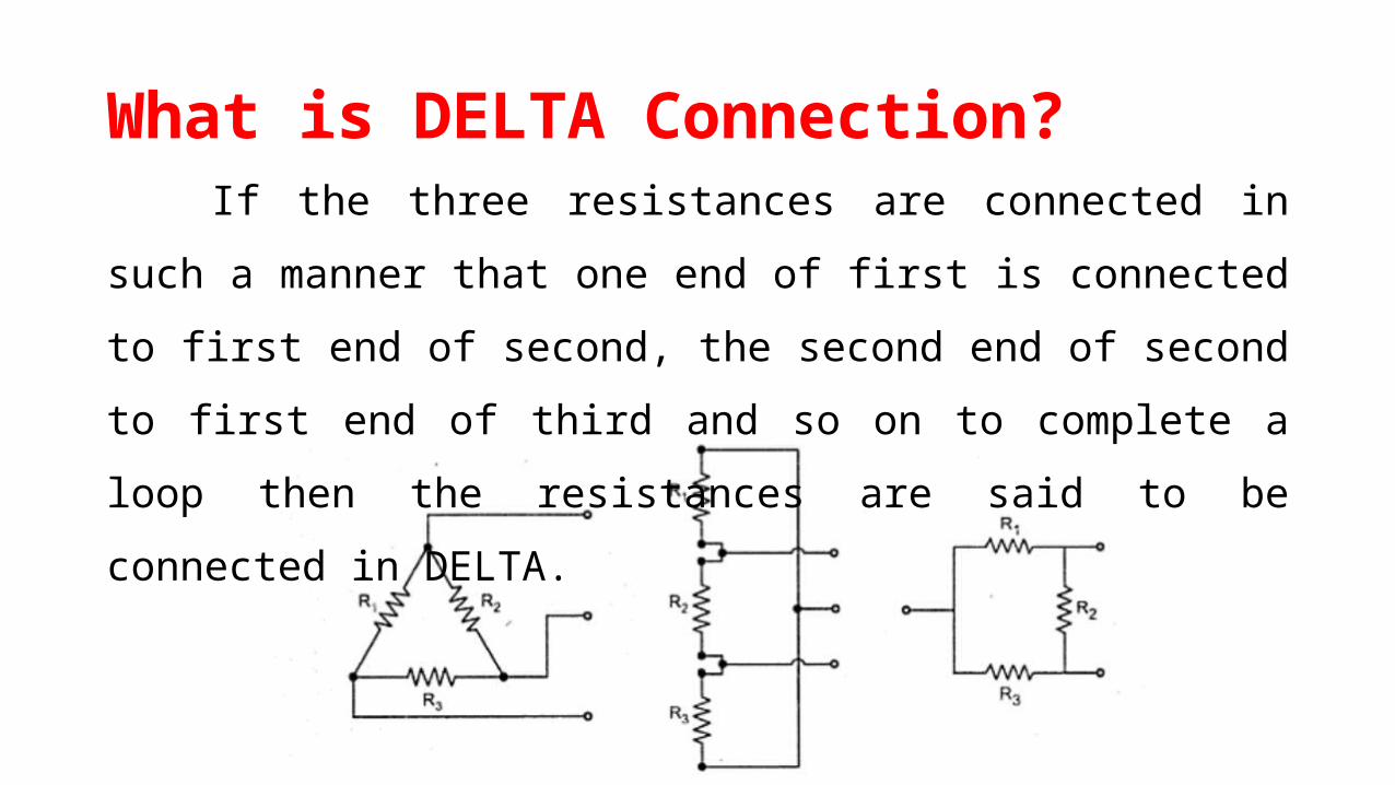
What is DELTA Connection?If the three resistances are connected in such a manner that one
end of first is connected to first end of second, the second end of
second to first end of third and so on to complete a loop then the
resistances are said to be connected in DELTA.
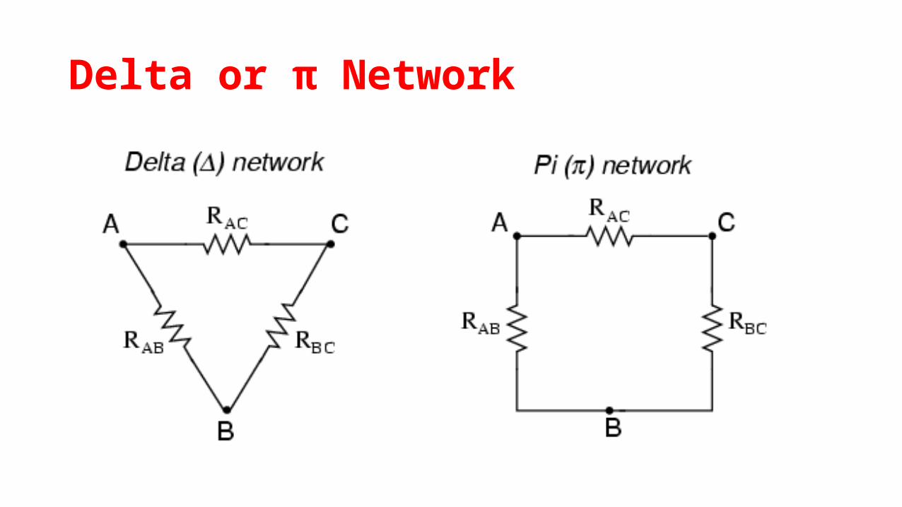
Delta or π Network
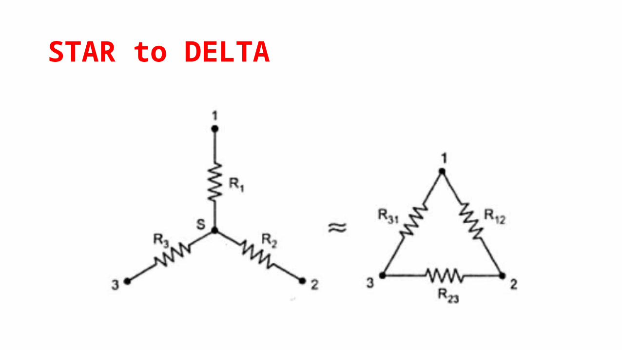
STAR to DELTA

DELTA to STAR
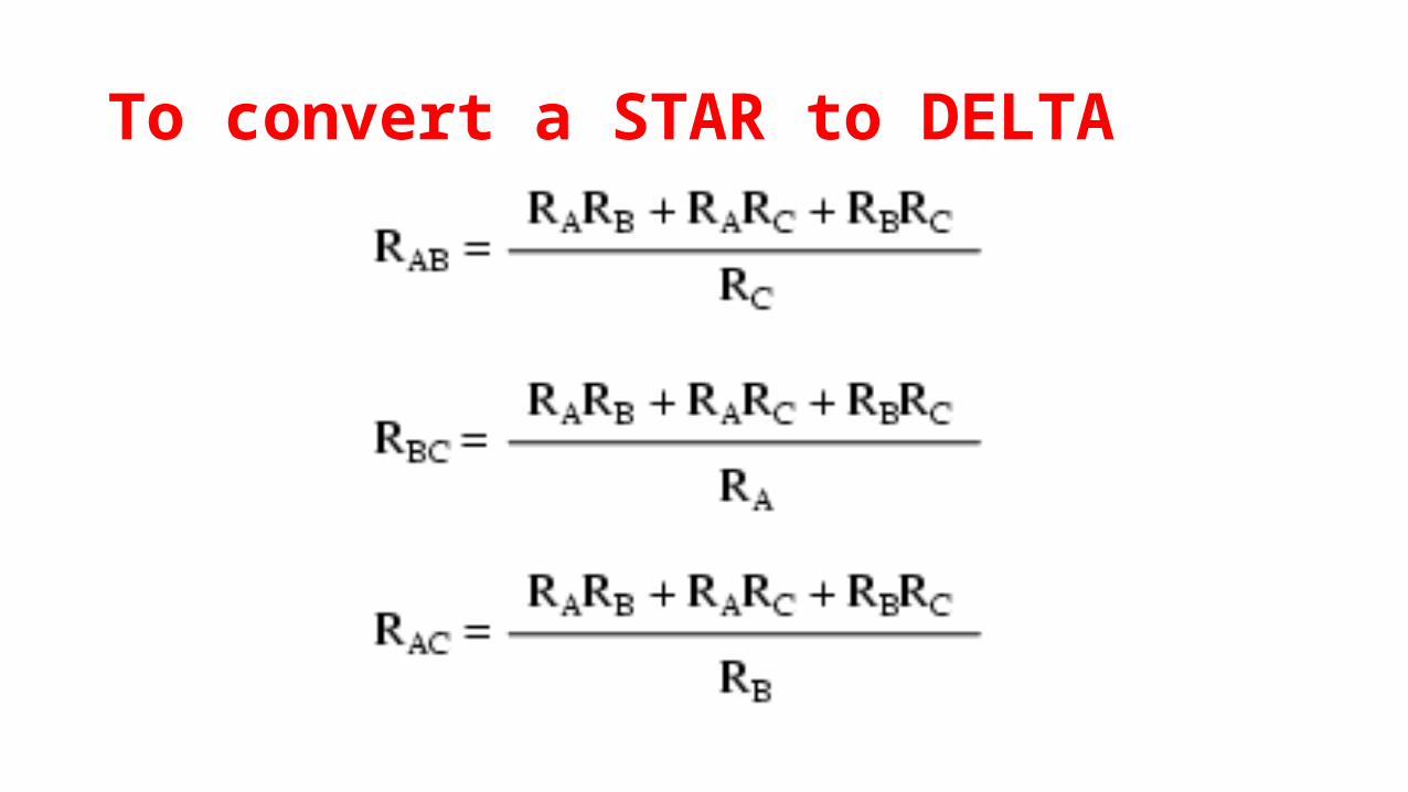
To convert a STAR to DELTA
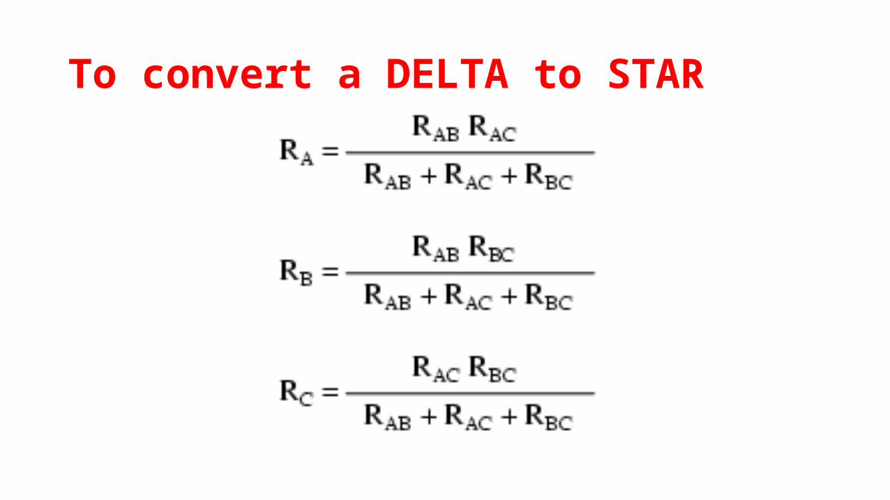
To convert a DELTA to STAR

Example 1-Convert given DELTA into STAR
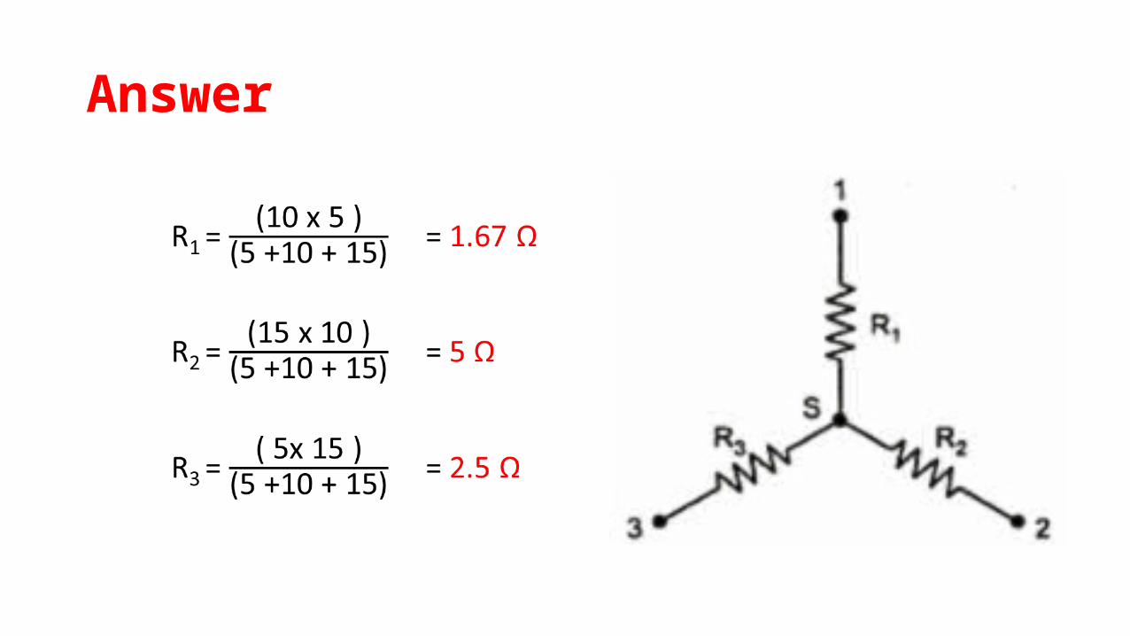
Answer

Example 2-Convert given STAR into DELTA
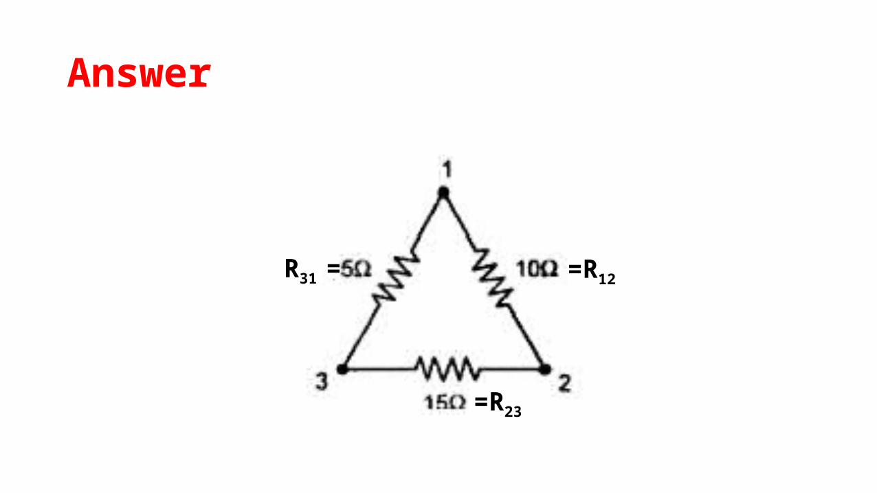
Answer
=R12
=R23
R31 =
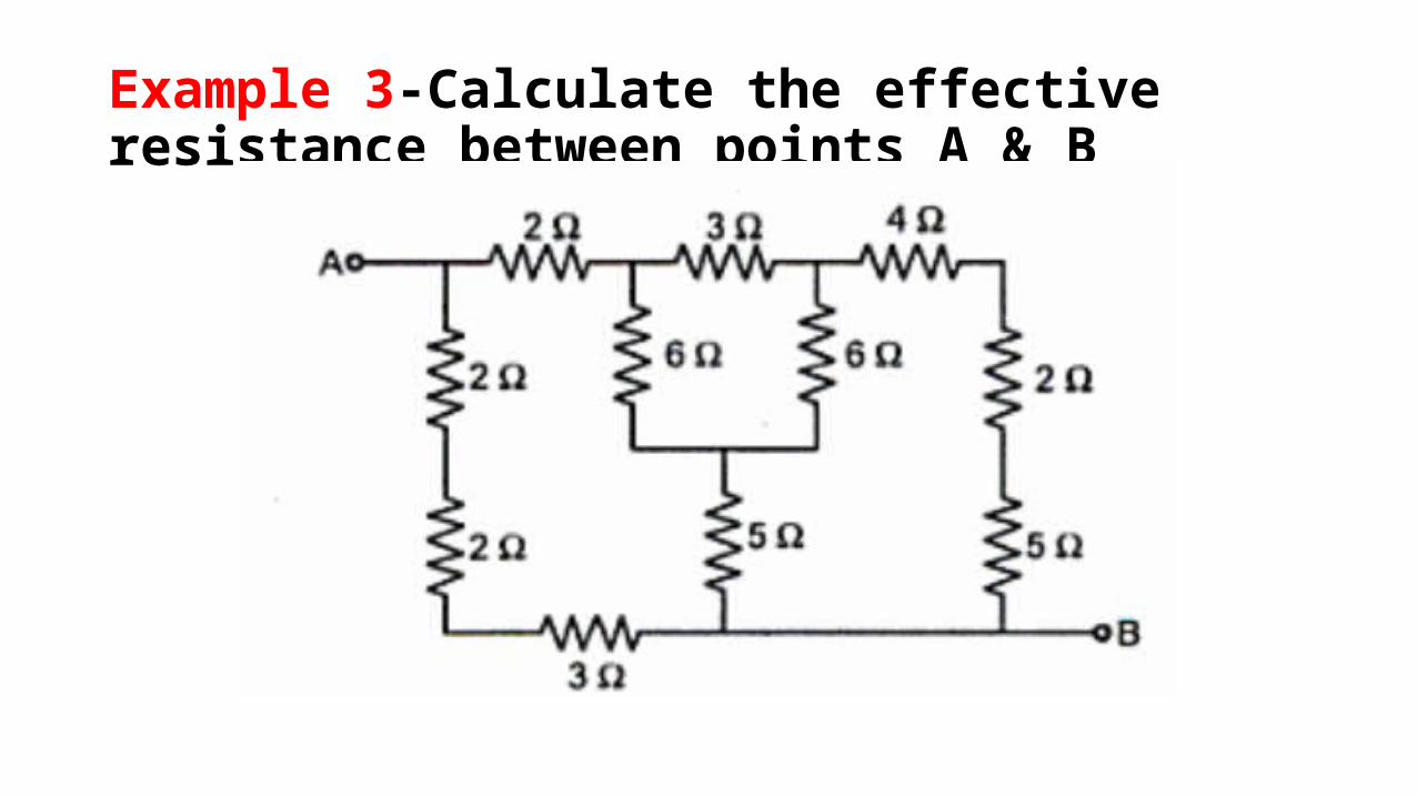
Example 3-Calculate the effective resistance between points A & B
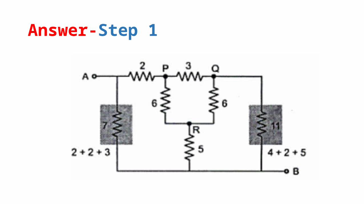
Answer-Step 1
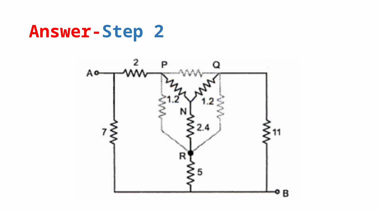
Answer-Step 2

Answer-Step 3

Answer-Step 4 & 5
RAB = 3.69 Ω
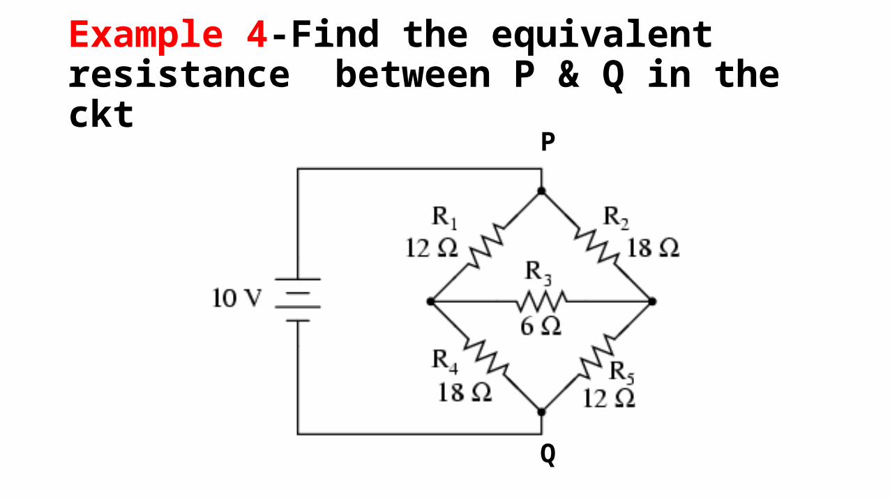
Example 4-Find the equivalent resistance between P & Q in the ckt
P
Q

Solution

Solution
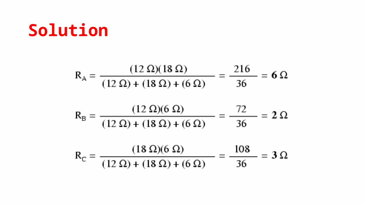
Solution

Solution
Req =14.571Ω

Example 5-In the circuit shown, find the resistance between M and N.

Solution- Step 1
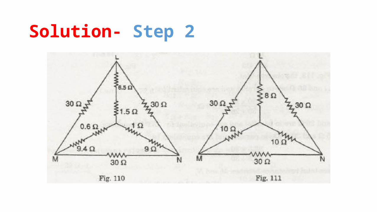
Solution- Step 2
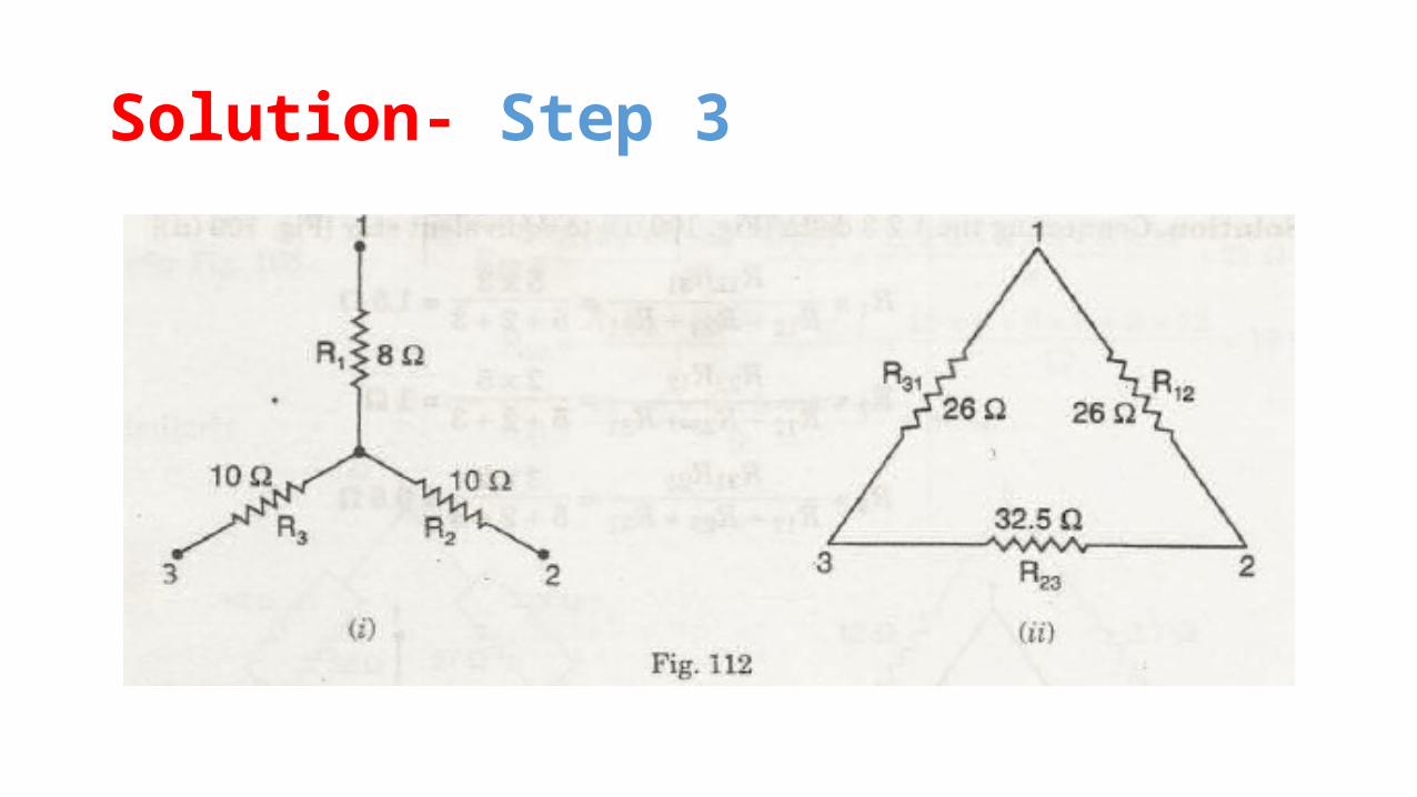
Solution- Step 3
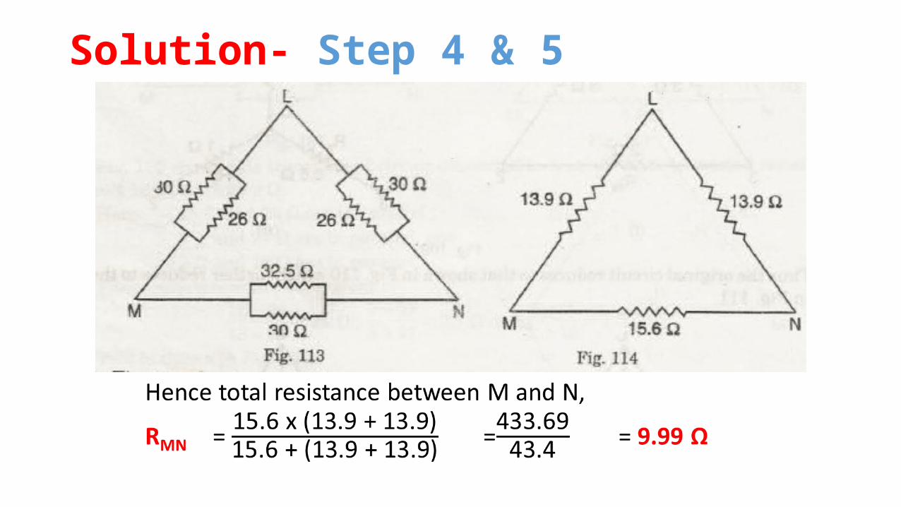
Solution- Step 4 & 5